WO2016125546A1 - Connecteur - Google Patents
Connecteur Download PDFInfo
- Publication number
- WO2016125546A1 WO2016125546A1 PCT/JP2016/050836 JP2016050836W WO2016125546A1 WO 2016125546 A1 WO2016125546 A1 WO 2016125546A1 JP 2016050836 W JP2016050836 W JP 2016050836W WO 2016125546 A1 WO2016125546 A1 WO 2016125546A1
- Authority
- WO
- WIPO (PCT)
- Prior art keywords
- contact
- switch
- fixed
- movable
- connector
- Prior art date
- Legal status (The legal status is an assumption and is not a legal conclusion. Google has not performed a legal analysis and makes no representation as to the accuracy of the status listed.)
- Ceased
Links
Images









Classifications
-
- H—ELECTRICITY
- H01—ELECTRIC ELEMENTS
- H01R—ELECTRICALLY-CONDUCTIVE CONNECTIONS; STRUCTURAL ASSOCIATIONS OF A PLURALITY OF MUTUALLY-INSULATED ELECTRICAL CONNECTING ELEMENTS; COUPLING DEVICES; CURRENT COLLECTORS
- H01R13/00—Details of coupling devices of the kinds covered by groups H01R12/70 or H01R24/00 - H01R33/00
- H01R13/66—Structural association with built-in electrical component
- H01R13/70—Structural association with built-in electrical component with built-in switch
- H01R13/707—Structural association with built-in electrical component with built-in switch interlocked with contact members or counterpart
-
- H—ELECTRICITY
- H01—ELECTRIC ELEMENTS
- H01H—ELECTRIC SWITCHES; RELAYS; SELECTORS; EMERGENCY PROTECTIVE DEVICES
- H01H9/00—Details of switching devices, not covered by groups H01H1/00 - H01H7/00
- H01H9/30—Means for extinguishing or preventing arc between current-carrying parts
- H01H9/44—Means for extinguishing or preventing arc between current-carrying parts using blow-out magnet
- H01H9/443—Means for extinguishing or preventing arc between current-carrying parts using blow-out magnet using permanent magnets
-
- H—ELECTRICITY
- H01—ELECTRIC ELEMENTS
- H01H—ELECTRIC SWITCHES; RELAYS; SELECTORS; EMERGENCY PROTECTIVE DEVICES
- H01H15/00—Switches having rectilinearly-movable operating part or parts adapted for actuation in opposite directions, e.g. slide switch
- H01H15/02—Details
- H01H15/06—Movable parts; Contacts mounted thereon
- H01H15/10—Operating parts
- H01H15/102—Operating parts comprising cam devices
-
- H—ELECTRICITY
- H01—ELECTRIC ELEMENTS
- H01R—ELECTRICALLY-CONDUCTIVE CONNECTIONS; STRUCTURAL ASSOCIATIONS OF A PLURALITY OF MUTUALLY-INSULATED ELECTRICAL CONNECTING ELEMENTS; COUPLING DEVICES; CURRENT COLLECTORS
- H01R13/00—Details of coupling devices of the kinds covered by groups H01R12/70 or H01R24/00 - H01R33/00
- H01R13/66—Structural association with built-in electrical component
- H01R13/70—Structural association with built-in electrical component with built-in switch
-
- H—ELECTRICITY
- H01—ELECTRIC ELEMENTS
- H01R—ELECTRICALLY-CONDUCTIVE CONNECTIONS; STRUCTURAL ASSOCIATIONS OF A PLURALITY OF MUTUALLY-INSULATED ELECTRICAL CONNECTING ELEMENTS; COUPLING DEVICES; CURRENT COLLECTORS
- H01R24/00—Two-part coupling devices, or either of their cooperating parts, characterised by their overall structure
- H01R24/20—Coupling parts carrying sockets, clips or analogous contacts and secured only to wire or cable
- H01R24/22—Coupling parts carrying sockets, clips or analogous contacts and secured only to wire or cable with additional earth or shield contacts
-
- H—ELECTRICITY
- H01—ELECTRIC ELEMENTS
- H01H—ELECTRIC SWITCHES; RELAYS; SELECTORS; EMERGENCY PROTECTIVE DEVICES
- H01H1/00—Contacts
- H01H1/12—Contacts characterised by the manner in which co-operating contacts engage
- H01H1/14—Contacts characterised by the manner in which co-operating contacts engage by abutting
- H01H1/24—Contacts characterised by the manner in which co-operating contacts engage by abutting with resilient mounting
- H01H1/26—Contacts characterised by the manner in which co-operating contacts engage by abutting with resilient mounting with spring blade support
-
- H—ELECTRICITY
- H01—ELECTRIC ELEMENTS
- H01H—ELECTRIC SWITCHES; RELAYS; SELECTORS; EMERGENCY PROTECTIVE DEVICES
- H01H1/00—Contacts
- H01H1/12—Contacts characterised by the manner in which co-operating contacts engage
- H01H1/14—Contacts characterised by the manner in which co-operating contacts engage by abutting
- H01H1/32—Self-aligning contacts
-
- H—ELECTRICITY
- H01—ELECTRIC ELEMENTS
- H01H—ELECTRIC SWITCHES; RELAYS; SELECTORS; EMERGENCY PROTECTIVE DEVICES
- H01H1/00—Contacts
- H01H1/50—Means for increasing contact pressure, preventing vibration of contacts, holding contacts together after engagement, or biasing contacts to the open position
-
- H—ELECTRICITY
- H01—ELECTRIC ELEMENTS
- H01H—ELECTRIC SWITCHES; RELAYS; SELECTORS; EMERGENCY PROTECTIVE DEVICES
- H01H1/00—Contacts
- H01H2001/0005—Redundant contact pairs in one switch for safety reasons
-
- H—ELECTRICITY
- H01—ELECTRIC ELEMENTS
- H01R—ELECTRICALLY-CONDUCTIVE CONNECTIONS; STRUCTURAL ASSOCIATIONS OF A PLURALITY OF MUTUALLY-INSULATED ELECTRICAL CONNECTING ELEMENTS; COUPLING DEVICES; CURRENT COLLECTORS
- H01R13/00—Details of coupling devices of the kinds covered by groups H01R12/70 or H01R24/00 - H01R33/00
- H01R13/02—Contact members
- H01R13/10—Sockets for co-operation with pins or blades
- H01R13/14—Resiliently-mounted rigid sockets
-
- H—ELECTRICITY
- H01—ELECTRIC ELEMENTS
- H01R—ELECTRICALLY-CONDUCTIVE CONNECTIONS; STRUCTURAL ASSOCIATIONS OF A PLURALITY OF MUTUALLY-INSULATED ELECTRICAL CONNECTING ELEMENTS; COUPLING DEVICES; CURRENT COLLECTORS
- H01R2103/00—Two poles
Definitions
- the present invention relates to a connector.
- connections Generally, electric power is supplied to electrical devices via connectors.
- the connector used at this time is electrically connected by fitting a convex male connector and a concave female connector.
- the human body may be affected or the operation of the electronic component may be affected.
- the connector When such high voltage power is used for information equipment, the connector must be different from the connector used for a normal AC commercial power supply.
- a connector incorporating a switch when the voltage supplied from the power source is a high voltage / direct current, the currently used switch cannot be used as it is. For example, when the power supplied from the power source is DC 400V, it is dangerous to use the switch as it is because the switch used for the current AC does not ensure sufficient safety and reliability.
- the connector includes two connection terminals that are electrically connected to terminals of another connector, and a switch that is connected to the connection terminal.
- the switch includes a first fixed part having a fixed contact, a first movable part having a movable contact that can contact the fixed contact, and a first switch connected to one connection terminal; And a second switch having a second fixed part having a fixed contact and a second movable part having a movable contact that can come into contact with the fixed contact, and connected to the other connection terminal.
- the first fixed portion and the second fixed portion, or the first movable portion and the second movable portion include a plurality of contacts.
- the connector is compatible with a power supply having a voltage higher than that of the current commercial power supply or a DC power supply, and can safely supply power from these power supplies.
- a connector can be provided.
- the high voltage means “over 750 VDC” defined in the electrical equipment technical standards, or “DC 1500 V or higher” which is an international regulation by the International Electrotechnical Commission (IEC). ”And a voltage exceeding a safe low voltage (less than 60 V DC).
- FIGS. 6 to 8 A connector in the first embodiment will be described.
- the connector 10 in this embodiment is shown in FIGS. 6 to 8 and is connected to the plug connector 200 shown in FIGS. 1 to 5.
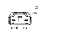
- the plug connector 200 will be described with reference to FIGS. 1 is a perspective view of the plug connector 200, FIG. 2 is a top view, FIG. 3 is a side view, FIG. 4 is a bottom view, and FIG. 5 is a front view.
- the plug connector 200 includes a cover 210 formed of an insulator and three plug terminals 221, 222, and 223.
- a power cable 230 is connected to the side of the cover 210 opposite to the side where the plug terminals 221, 222, and 223 are provided.
- the plug terminal 221 is a GND terminal and is longer than the plug terminals 222 and 223.
- the plug terminals 222 and 223 are terminals to which electric power is supplied by being electrically connected to the terminals of the connector 10.
- the cover 210 of the plug connector 200 is provided with a protection part 211 formed so as to cover a part of the plug terminals 221, 222, and 223. Further, the cover 210 is provided with an opening 212 for preventing the plug connector 200 from being detached from the connector 10.
- FIGS. 6 is a perspective view of the connector 10
- FIG. 7 is a front view
- FIG. 8 is a side view.
- the connector 10 is covered with a housing 50, and jack openings 21, 22, and 23 into which plug terminals 221, 222, and 223 of the plug connector 200 are respectively inserted, and a groove portion into which the protection part 211 of the plug connector 200 is inserted.
- the slide 40 can be slid to an “ON” position or an “OFF” position. By sliding the slide 40, power supply via the connector 10 can be switched.
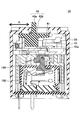
- FIG. 9 is a cross-sectional view of the connector 10.
- an operation unit 40 a that is a part of the slide 40 protrudes outward from an opening provided in the housing 50.
- the switch 100 provided inside the housing 50 can be operated.
- the slide 40 has a slide main body 40b located in the housing 50, and the slide main body 40b is connected to the slide link 41.
- the slide link 41 moves substantially parallel to the slide direction indicated by the arrow A as the slide 40 moves, and is formed in an L shape.
- One end of the slide link 41 enters the opening 42 a of the contact slide 42.
- the contact slide 42 pushes the button 160 by moving the slide 40 in the right direction of the arrow A as will be described later.
- the opening 42a is formed in an elongated shape along the moving direction of the slide link 41, that is, the sliding direction.
- the contact slide 42 is provided with a contact portion 42b (shown in FIG. 16) extending in a substantially vertical downward direction with respect to the slide direction. The tip of the contact portion 42 b is in contact with the upper surface of the button 160 of the switch 100.
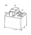
- the switch 100 of the connector 10 is a switch for switching power supply, and is also referred to as a power switch.
- FIG. 10 shows a perspective view of the switch 100
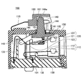
- FIG. 11 shows an internal structure of the switch 100.
- the switch 100 can perform on / off control of power supply by contact / non-contact between the fixed contact 111 of the fixed unit 110 and the movable contact 121 of the movable unit 120. It is.
- the fixed portion 110 is made of a conductive material, and a fixed contact 111 is provided at one end of the fixed spring 112.
- the fixed spring 112 is formed by bending a metal plate made of copper or an alloy containing copper, and the fixed contact 111 is formed of an alloy of silver and copper.
- the other end of the fixed spring 112 is fixed to the base block main body 131 of the base block 130 and is supported by the support portion 132 in the middle of the fixed spring 112.
- the movable portion 120 is made of a conductive material, and a movable contact 121 that contacts the fixed contact 111 is provided at one end of the movable plate 122, and the movable plate 122 and the movable spring 123 are connected to each other.
- the movable plate 122 and the movable spring 123 are formed by bending a metal plate or the like made of copper or an alloy containing copper, and the movable contact 121 is formed of an alloy of silver and copper.
- the other end of the movable spring 123 is fixed to the base block main body 131.
- the movable spring 123 has flexibility and can move the movable contact 121 in the vertical direction.
- an insulating wall 133 made of a flame-retardant resin material or the like is provided between a portion where the fixed spring 112 of the base block 130 is fixed and a portion where the movable spring 123 is fixed,
- the movable spring 123 is bent in such a shape as to wrap around the insulating wall 133.
- the upper surface of the movable plate 122 is in contact with the contact portion 141 of the card 140, and the lower surface of the movable plate 122 is in contact with the contact portion 142 of the card 140.
- the movable plate 122 comes into contact with the contact portion 141 or the contact portion 142 to apply a force to the movable plate 122, and the movable contact 121 is moved in the vertical direction. Can be moved. Since the movable plate 122 slides at the contact portion 141 and the contact portion 142, the surface of the contact portion 141 and the contact portion 142 is formed of fluororesin or the like in order to reduce the frictional resistance with the movable plate 122.
- a surface layer may be provided.
- the fixed part 110 and the movable part 120 are installed in an area surrounded by the base block 130 and the case 150.
- the card 140 has a protrusion 144 that protrudes to the outside from an opening 151 provided in the case 150, and a card main body 145 that is positioned inside a region surrounded by the base block 130 and the case 150.
- the contact part 141 and the contact part 142 are also provided in the area surrounded by the base block 130 and the case 150.
- the card 140, the base block 130, and the case 150 are formed of an insulating material such as a resin material.
- a button 160 that is pressed to rotate the card 140 is provided outside the case 150.
- the card 140 is in contact with the inner wall portion 161 of the button 160 at a contact portion 144 a provided on the upper portion of the projection portion 144.
- the contact part 144a slides on the surface of the inner wall part 161, in order to reduce the frictional resistance between the contact part 144a and the inner wall part 161, the surface formed on the surface of the inner wall part 161 by a fluororesin or the like A layer may be provided.
- a release spring 170 having one end connected to the case 150 and the other end connected to the button 160 is provided outside the case 150. The release spring 170 returns the button 160 upward by the spring force when the slide 40 is moved in the left direction of the arrow A in FIG. When the button 160 returns upward, the card 140 moves upward.
- FIG. 12 shows a state where the movable contact 121 and the fixed contact 111 are in contact with each other. Since the button 160 is maintained at the position shown in FIG. 12 by the contact portion 42b of the contact slide 42, the contact between the movable contact 121 and the fixed contact 111 is maintained.
- the contact slide 42 is moved in the direction opposite to that when the switch is turned on, as shown later, in the left side of FIG.
- the button 160 moves upward by the spring force of the breaking spring 170.
- the card 140 is pulled up by the button 160 and rotates around the rotation shaft 143, and an upward force is applied to the movable plate 122 contacting the contact portion 142. Since the hooking portion 146 provided on the upper portion of the card 140 shown in FIG. 20 is hooked on the button 160, the card 140 is pulled up by moving the button 160 upward.
- the movable contact 121 is moved upward by the upward force applied to the movable plate 122, so that the movable contact 121 and the fixed contact 111 can be separated as shown in FIG. 11, and the power supply is stopped. be able to.
- the arc since an arc may be generated between the movable contact 121 and the fixed contact 111, in the vicinity of the contact position between the movable contact 121 and the fixed contact 111, the arc can be blown by a magnetic force.
- a permanent magnet (not shown) that generates a magnetic field substantially perpendicular to the direction in which the arc is generated is provided.
- the movable contact 121 When the power supply is cut off by the switch 100, the movable contact 121 is not moved upward by using the spring force of the movable spring 123, but the button 160 is moved by the release spring 170 provided outside the case 150. By pushing up, the card 140 is moved upward and the switch 100 is turned off. For this reason, even when the movable spring 123 does not have enough force to pull the movable contact 121 away from the fixed contact 111, the switch can be turned off. Further, even when a part of the movable spring 123 is melted by heat and the function as a spring is lost, the switch is turned off by the spring property of the breaking spring 170 without using the spring force of the movable spring 123. The supply of electric power can be cut off reliably. Further, since the release spring 170 is installed outside the case 150, it is not affected by the heat generated inside the case 150.
- an insulating wall 133 is provided between a portion of the base block 130 where the fixed spring 112 is fixed and a portion where the movable spring 123 is fixed. Even if dissolution of the fixed part 110 and the movable part 120 proceeds, the dissolved part of the fixed part 110 and the dissolved part of the movable part 120 are separated by the insulating wall 133. Therefore, it is possible to prevent the current from continuing to flow while the fixed portion 110 and the movable portion 120 remain melted.
- the switch 100 can be turned on and off by switching the connector 10 on and off in the state of FIG. Specifically, the operation unit 40a of the slide 40 is slid from the “OFF” position shown in FIG. 14 to the “ON” position shown in FIG. By the slide operation of the slide 40, the upper portion 165 of the upper surface of the button 160 is pushed by the contact portion 42b, the button 160 is lowered, and the switch 100 is changed from the off state shown in FIG. 9 to the on state shown in FIG. When the switch is turned from on to off, the operation unit 40a is slid from the “ON” side shown in FIG. 15 to the “OFF” side shown in FIG.
- a hook (not shown) provided in the connector 10 enters the opening 212 of the plug connector 200 shown in FIG.
- the hook By fitting the hook, the fitting state between the connector 10 and the plug connector 200 is maintained, and the plug connector 200 can be prevented from coming off. Further, when the switch 100 is turned off, the hook is detached from the opening 212 and the plug connector 200 can be detached from the connector 10.
- the switch of the connector 10 may be provided with two each of a fixed part and a movable part constituting the switch.
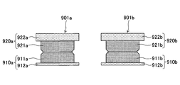
- two sets of a first fixed portion 910a and a second fixed portion 910b, and a first movable portion 920a and a second movable portion 920b are provided.
- the first fixed portion 910a has a first fixed contact 911a and a first fixed spring 912a
- the second fixed portion 910b has a second fixed contact 911b and a second fixed spring 912b.
- the first movable portion 920a has a first movable contact 921a and a first movable plate 922a
- the second movable portion 920b has a second movable contact 921b and a second movable plate 922b. is doing.
- the first fixed portion 910a and the first movable portion 920a form a first switch 901a
- the second fixed portion 910b and the second movable portion 920b form a second switch 901b.
- the switch is turned on when both the first switch 901a and the second switch 901b are turned on, and either the first switch 901a or the second switch 901b is turned on.
- the switch turns off when it turns off.
- the first switch 901a is turned on when the first fixed contact 911a and the first movable contact 921a come into contact with each other, and is turned off when the first fixed contact 911a is separated from the first movable contact 921a.
- the second switch 901b is turned on when the second fixed contact 911b and the second movable contact 921b come into contact with each other, and is turned off when the second fixed contact 911b is separated from the second movable contact 921b. It becomes.
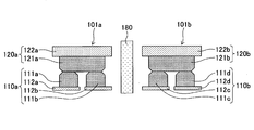
- the fixed part or the movable part of the first switch 101a and the second switch 101b included in the switch 100 is configured by twin contacts.
- the first fixed portion 110a and the second fixed portion 110b are twin contacts.
- the first fixed portion 110a has two fixed contacts, a first fixed contact 111a and a second fixed contact 111b.
- the first fixed contact 111a is installed on the first fixed spring 112a
- the second fixed contact 111b is installed on the second fixed spring 112b.
- the second fixed portion 110b has two fixed contacts, a third fixed contact 111c and a fourth fixed contact 111d.
- the third fixed contact 111c is installed on the third fixed spring 112c
- the fourth fixed contact 111d is installed on the fourth fixed spring 112d.
- the first fixed spring 112a and the second fixed spring 112b are electrically connected, and the first fixed spring 112a is formed by providing a groove in the integrally formed fixed spring. And the second fixing spring 112b are separated. Similarly, the third fixed spring 112c and the fourth fixed spring 112d are separated from each other by providing a groove in the integrally formed fixed spring.
- the first movable part 120a has a single first movable contact 121a.
- the first movable contact 121a is installed on the first movable plate 122a, and the first movable plate 122a is connected to the first movable spring 123a.
- the second movable part 120b has a single second movable contact 121b.
- the second movable contact 121b is installed on the second movable plate 122b, and the second movable plate 122b is connected to the second movable spring 123b.
- the first switch 101a is formed by the first fixed portion 110a and the first movable portion 120a.
- the second fixed portion 11b and the second movable portion 120b form a second switch 101b.
- the switch 100 is turned on when both the first switch 101a and the second switch 101b are turned on, and is turned off when either the first switch 101a or the second switch 101b is turned off. Become.
- the first switch 101a is a twin contact switch
- at least one of the first fixed contact 111a or the second fixed contact 111b and the first movable contact 121a come into contact with each other.
- the switch 101a is turned on.
- the second switch 101b is also a twin contact switch, at least one of the third fixed contact 111c and the fourth fixed contact 111d and the second movable contact 121b come into contact with each other, so that the second switch 101b is a second contact.
- the switch 101b is turned on.
- a permanent magnet 180 is installed between the first switch 101a and the second switch 101b.
- the arc generated between the fixed contact and the movable contact can be blown away by the magnetic field generated by the permanent magnet 180.
- a magnetic field is generated in the direction indicated by the one-dot chain line arrow by the permanent magnet 180 installed between the first switch 101a and the second switch 101b.
- the arc generated between the contacts due to the current flowing in the direction can be blown off in the direction indicated by the two-dot chain line arrow.
- the first switch 101a and the second switch 101b are not necessarily turned on at the same time, and either the first switch 901a or the second switch 901b. May be turned on first and the other switch turned on later.
- the switch that is turned on later is turned on, the switch is turned on. Therefore, an arc due to an inrush current due to chattering or the like may occur between the contact points of the switch that is turned on later, causing damage to the contact surface of the switch that is turned on later, causing a conduction failure.
- the first switch 901a is turned on first, and the second switch 901b is turned on later.
- the switch 901b is turned on first and the first switch 901a is turned on later. Therefore, the probability that an inrush current flows between the first fixed contact 911a and the first movable contact 921a and the second fixed contact 111b and the second movable contact 921b during one ON operation.
- the probability that an inrush current flows is considered to be about 1 ⁇ 2 each.
- the switch 100 in the present embodiment is provided with the first fixed contact 111a, the second fixed contact 111b, the third fixed contact 111c, and the fourth fixed contact 111d, and four fixed contacts.
- an inrush current is generated between the fixed contact and the movable contact that come in contact with the tip of the switch that is turned on later in the first switch 101a or the second switch 101b.
- the third fixed contact 111c is the fourth fixed contact 111c.
- an inrush current flows between the third fixed contact 111c and the second movable contact 121b.
- the fourth fixed contact 111d is the first fixed contact 111d.
- the second movable contact 121b comes into contact with the third fixed contact 111c prior to the third fixed contact 111c, an inrush current flows between the fourth fixed contact 111d and the second movable contact 121b.
- the first fixed contact 111a is the first fixed contact 111a.
- an inrush current flows between the first fixed contact 111a and the first movable contact 121a.
- the second fixed contact 111b is When the first movable contact 111a comes into contact with the first movable contact 121a before the first fixed contact 111a, an inrush current flows between the second fixed contact 111b and the first movable contact 121a.
- the probability that an inrush current flows to each fixed contact in one ON operation is 1/4.
- the probability that an inrush current flows to each fixed contact is half that of the example shown in FIG. 17, so that even if the number of ON times is the same, the damage given to each fixed contact is reduced. This can reduce the life of the connector.
- the switch 100 When the switch is turned off from on, the switch 100 generates an arc between the fixed contact and the movable contact that are separated later among the contact points of the switch that is turned off before the first switch 101a or the second switch 101b. Arise.
- the fourth fixed contact 111d is the third fixed contact 111a.
- an arc is generated between the fourth fixed contact 111d and the second movable contact 121b.
- the first fixed contact 111a is the second fixed contact 111a.
- an arc is generated between the first fixed contact 111a and the first movable contact 121a.
- the second fixed contact 111b is the first fixed contact.
- an arc is generated between the second fixed contact 111b and the first movable contact 121a.
- the probability that an arc will occur at each fixed contact during one off operation is 1/4.
- the probability of occurrence of an arc at one fixed contact is halved compared to the example of FIG. 17, even if the number of off times is the same, the damage given to each fixed contact can be reduced, and the life is extended. Can be made.
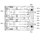
- the switch according to this embodiment shown in FIG. 33 has a first switch 301a and a second switch 301b in which each movable part is formed by a twin contact. As shown in FIGS. 34 and 35, the switch is provided with a first fixed portion 310a and a second fixed portion 310b, and a first movable portion 320a and a second movable portion 320b.
- the first fixed portion 310a has a first fixed contact 311a installed on the first fixed spring 312a.
- the second fixed portion 310b has a second fixed contact 311b installed on the second fixed spring 312b.
- the first movable part 320a has a first movable contact 321a and a second movable contact 321b.
- the first movable contact 321a is installed on the first movable plate 322a
- the second movable contact 321b is installed on the second movable plate 322b.
- the first movable plate 322a and the second movable plate 322b are connected to the first movable spring 323a.
- the second movable portion 320b has a third movable contact 321c and a fourth movable contact 321d.
- the third movable contact 321c is installed on the third movable plate 322c
- the fourth movable contact 321d is installed on the fourth movable plate 322d.
- the third movable plate 322c and the fourth movable plate 322d are connected to the second movable spring 323b.
- the first switch 301a is formed by the first fixed portion 310a and the first movable portion 320a.
- the second switch 301b is formed by the second fixed portion 310b and the second movable portion 320b.
- the first switch 301a is a twin contact switch, and is turned on when the first fixed contact 311a and at least one of the first movable contact 321a or the second movable contact 321b come into contact with each other.
- the first fixed contact 311a is turned off when it is separated from both the first movable contact 321a and the second movable contact 321b.
- the second switch 301b is also a twin contact switch, and is turned on when the second fixed contact 311b and at least one of the third movable contact 321c or the fourth movable contact 321d come into contact with each other,
- the second fixed contact 311b is turned off by moving away from both the third movable contact 321c and the fourth movable contact 321d.
- a permanent magnet 180 is installed between the first switch 301a and the second switch 301b.
- the arc generated between the fixed contact and the movable contact can be blown off by the magnetic field of the permanent magnet 180.
- the permanent magnet 180 installed between the first switch 301a and the second switch 301b generates a magnetic field in the direction indicated by the one-dot chain line arrow, and is indicated by the dashed arrow.
- the arc generated between the contacts due to the current flowing in the direction can be blown off in the direction indicated by the two-dot chain line arrow.
Landscapes
- Details Of Connecting Devices For Male And Female Coupling (AREA)
Abstract
L'invention concerne un connecteur qui comprend deux bornes de connexion devant être connectées électriquement aux bornes d'un autre connecteur, et un commutateur connecté aux bornes de connexion. Le commutateur comprend : un premier commutateur comprenant une première partie fixe ayant un contact fixe et une première partie mobile ayant un contact mobile conçu pour entrer en contact avec le contact fixe, le premier commutateur étant connecté à une borne de connexion ; et un second commutateur comprenant une seconde partie fixe ayant un contact fixe et une seconde partie mobile ayant un contact mobile conçu pour entrer en contact avec le contact fixe, le second commutateur étant connecté à l'autre borne de connexion. La première partie fixe et la seconde partie fixe, ou la première partie mobile et la seconde partie mobile sont dotées d'une pluralité de contacts.
Priority Applications (4)
| Application Number | Priority Date | Filing Date | Title |
|---|---|---|---|
| US15/546,753 US20180019553A1 (en) | 2015-02-06 | 2016-01-13 | Connector |
| EP18201188.2A EP3467961A1 (fr) | 2015-02-06 | 2016-01-13 | Connecteur |
| EP16746377.7A EP3255740A4 (fr) | 2015-02-06 | 2016-01-13 | Connecteur |
| CN201680008308.8A CN107210567A (zh) | 2015-02-06 | 2016-01-13 | 连接器 |
Applications Claiming Priority (2)
| Application Number | Priority Date | Filing Date | Title |
|---|---|---|---|
| JP2015022619A JP6469468B2 (ja) | 2015-02-06 | 2015-02-06 | コネクタ |
| JP2015-022619 | 2015-02-06 |
Publications (1)
| Publication Number | Publication Date |
|---|---|
| WO2016125546A1 true WO2016125546A1 (fr) | 2016-08-11 |
Family
ID=56563897
Family Applications (1)
| Application Number | Title | Priority Date | Filing Date |
|---|---|---|---|
| PCT/JP2016/050836 Ceased WO2016125546A1 (fr) | 2015-02-06 | 2016-01-13 | Connecteur |
Country Status (5)
| Country | Link |
|---|---|
| US (1) | US20180019553A1 (fr) |
| EP (2) | EP3467961A1 (fr) |
| JP (1) | JP6469468B2 (fr) |
| CN (1) | CN107210567A (fr) |
| WO (1) | WO2016125546A1 (fr) |
Families Citing this family (1)
| Publication number | Priority date | Publication date | Assignee | Title |
|---|---|---|---|---|
| TWI679664B (zh) * | 2018-10-02 | 2019-12-11 | 易湘雲 | 開關的過熱破壞式斷電方法 |
Citations (4)
| Publication number | Priority date | Publication date | Assignee | Title |
|---|---|---|---|---|
| JPS585226U (ja) * | 1981-07-01 | 1983-01-13 | 株式会社東芝 | 双子接点 |
| JPS6160414U (fr) * | 1984-09-25 | 1986-04-23 | ||
| JPH0478720U (fr) * | 1990-11-19 | 1992-07-09 | ||
| WO2012063528A1 (fr) * | 2010-11-12 | 2012-05-18 | 富士通コンポーネント株式会社 | Connecteur et interrupteur |
Family Cites Families (18)
| Publication number | Priority date | Publication date | Assignee | Title |
|---|---|---|---|---|
| JPH0582208A (ja) | 1991-09-20 | 1993-04-02 | Fujitsu Ltd | コネクタ |
| JPH05242753A (ja) * | 1992-02-28 | 1993-09-21 | Matsushita Electric Works Ltd | 接点開閉装置及び電磁リレー |
| DE19636560A1 (de) * | 1996-09-09 | 1998-03-12 | Siemens Ag | Justierfrei einstellbare Kontaktkraft an Hilfsschaltern |
| JPH11250966A (ja) * | 1997-12-22 | 1999-09-17 | Whitaker Corp:The | コネクタ |
| JP3286783B2 (ja) * | 1999-02-18 | 2002-05-27 | 日本航空電子工業株式会社 | コンタクト |
| GB2353409A (en) * | 1999-08-17 | 2001-02-21 | Siemens Metering Ltd | Improvements in electrical contacts |
| JP4181307B2 (ja) * | 2001-01-19 | 2008-11-12 | 山一電機株式会社 | カードコネクタ |
| JP3790450B2 (ja) * | 2001-07-17 | 2006-06-28 | 富士通アクセス株式会社 | 電気コネクタ |
| US20050112959A1 (en) * | 2003-11-20 | 2005-05-26 | Kuang-Chih Lai | Large elastic momentum conduction member of IC device socket |
| JP5093015B2 (ja) * | 2008-09-16 | 2012-12-05 | 株式会社デンソー | 電磁継電器 |
| US20100323564A1 (en) * | 2009-06-19 | 2010-12-23 | Clark Stephen H | Bifurcated Electrical Contact |
| US8123551B1 (en) * | 2010-09-29 | 2012-02-28 | Cheng Uei Precision Industry Co., Ltd. | Battery connector |
| JP6054599B2 (ja) * | 2011-08-11 | 2016-12-27 | 富士通コンポーネント株式会社 | スイッチ及びコネクタ |
| JP5917852B2 (ja) * | 2011-08-11 | 2016-05-18 | 富士通コンポーネント株式会社 | スイッチ及びコネクタ |
| JP5838056B2 (ja) * | 2011-08-11 | 2015-12-24 | 富士通コンポーネント株式会社 | スイッチ及びコネクタ |
| JP5917853B2 (ja) * | 2011-08-11 | 2016-05-18 | 富士通コンポーネント株式会社 | スイッチ及びコネクタ |
| US9033750B2 (en) * | 2012-08-15 | 2015-05-19 | Tyco Electronics Corporation | Electrical contact |
| JP6299097B2 (ja) | 2013-07-22 | 2018-03-28 | 株式会社リコー | 情報処理システム、情報処理方法、プログラム、及び記録媒体 |
-
2015
- 2015-02-06 JP JP2015022619A patent/JP6469468B2/ja not_active Expired - Fee Related
-
2016
- 2016-01-13 WO PCT/JP2016/050836 patent/WO2016125546A1/fr not_active Ceased
- 2016-01-13 US US15/546,753 patent/US20180019553A1/en not_active Abandoned
- 2016-01-13 CN CN201680008308.8A patent/CN107210567A/zh active Pending
- 2016-01-13 EP EP18201188.2A patent/EP3467961A1/fr not_active Withdrawn
- 2016-01-13 EP EP16746377.7A patent/EP3255740A4/fr not_active Withdrawn
Patent Citations (4)
| Publication number | Priority date | Publication date | Assignee | Title |
|---|---|---|---|---|
| JPS585226U (ja) * | 1981-07-01 | 1983-01-13 | 株式会社東芝 | 双子接点 |
| JPS6160414U (fr) * | 1984-09-25 | 1986-04-23 | ||
| JPH0478720U (fr) * | 1990-11-19 | 1992-07-09 | ||
| WO2012063528A1 (fr) * | 2010-11-12 | 2012-05-18 | 富士通コンポーネント株式会社 | Connecteur et interrupteur |
Non-Patent Citations (1)
| Title |
|---|
| See also references of EP3255740A4 * |
Also Published As
| Publication number | Publication date |
|---|---|
| JP2016146272A (ja) | 2016-08-12 |
| EP3255740A4 (fr) | 2019-01-09 |
| US20180019553A1 (en) | 2018-01-18 |
| JP6469468B2 (ja) | 2019-02-13 |
| EP3255740A1 (fr) | 2017-12-13 |
| EP3467961A1 (fr) | 2019-04-10 |
| CN107210567A (zh) | 2017-09-26 |
Similar Documents
| Publication | Publication Date | Title |
|---|---|---|
| JP5619576B2 (ja) | コネクタ及びスイッチ | |
| JP5917853B2 (ja) | スイッチ及びコネクタ | |
| JP6054600B2 (ja) | コネクタ | |
| JP6054599B2 (ja) | スイッチ及びコネクタ | |
| JP5917852B2 (ja) | スイッチ及びコネクタ | |
| EP3358594B1 (fr) | Disjoncteur à un seul étage | |
| JP5838056B2 (ja) | スイッチ及びコネクタ | |
| JP6618816B2 (ja) | コネクタ及びコネクタ装置 | |
| US9281635B2 (en) | Connector and connector bar | |
| WO2016125546A1 (fr) | Connecteur | |
| US9653855B2 (en) | Connector and connector unit | |
| JP6161974B2 (ja) | コネクタ | |
| US8383968B2 (en) | Lever switch for safe breaking of a circuit of an exercise apparatus | |
| JP5330196B2 (ja) | コネクタ装置、及び雄コネクタ | |
| JP6618817B2 (ja) | コネクタ | |
| JP6660190B2 (ja) | スイッチ及びコネクタ | |
| EP2423931A1 (fr) | Commutateur à levier pour l'interruption sécurisé d'un circuit d'un appareil d'exercice | |
| JP2020167034A (ja) | 電源回路遮断装置 |
Legal Events
| Date | Code | Title | Description |
|---|---|---|---|
| 121 | Ep: the epo has been informed by wipo that ep was designated in this application |
Ref document number: 16746377 Country of ref document: EP Kind code of ref document: A1 |
|
| WWE | Wipo information: entry into national phase |
Ref document number: 15546753 Country of ref document: US |
|
| REEP | Request for entry into the european phase |
Ref document number: 2016746377 Country of ref document: EP |
|
| NENP | Non-entry into the national phase |
Ref country code: DE |