WO2016129054A1 - Dispositif d'imagerie à zoom - Google Patents
Dispositif d'imagerie à zoom Download PDFInfo
- Publication number
- WO2016129054A1 WO2016129054A1 PCT/JP2015/053640 JP2015053640W WO2016129054A1 WO 2016129054 A1 WO2016129054 A1 WO 2016129054A1 JP 2015053640 W JP2015053640 W JP 2015053640W WO 2016129054 A1 WO2016129054 A1 WO 2016129054A1
- Authority
- WO
- WIPO (PCT)
- Prior art keywords
- lens
- lens group
- zoom
- refractive power
- image
- Prior art date
- Legal status (The legal status is an assumption and is not a legal conclusion. Google has not performed a legal analysis and makes no representation as to the accuracy of the status listed.)
- Ceased
Links
Images


Classifications
-
- G—PHYSICS
- G02—OPTICS
- G02B—OPTICAL ELEMENTS, SYSTEMS OR APPARATUS
- G02B7/00—Mountings, adjusting means, or light-tight connections, for optical elements
- G02B7/02—Mountings, adjusting means, or light-tight connections, for optical elements for lenses
- G02B7/04—Mountings, adjusting means, or light-tight connections, for optical elements for lenses with mechanism for focusing or varying magnification
- G02B7/10—Mountings, adjusting means, or light-tight connections, for optical elements for lenses with mechanism for focusing or varying magnification by relative axial movement of several lenses, e.g. of varifocal objective lens
-
- G—PHYSICS
- G02—OPTICS
- G02B—OPTICAL ELEMENTS, SYSTEMS OR APPARATUS
- G02B15/00—Optical objectives with means for varying the magnification
- G02B15/14—Optical objectives with means for varying the magnification by axial movement of one or more lenses or groups of lenses relative to the image plane for continuously varying the equivalent focal length of the objective
- G02B15/144—Optical objectives with means for varying the magnification by axial movement of one or more lenses or groups of lenses relative to the image plane for continuously varying the equivalent focal length of the objective having four groups only
- G02B15/1441—Optical objectives with means for varying the magnification by axial movement of one or more lenses or groups of lenses relative to the image plane for continuously varying the equivalent focal length of the objective having four groups only the first group being positive
- G02B15/144105—Optical objectives with means for varying the magnification by axial movement of one or more lenses or groups of lenses relative to the image plane for continuously varying the equivalent focal length of the objective having four groups only the first group being positive arranged +-+-
-
- G—PHYSICS
- G02—OPTICS
- G02B—OPTICAL ELEMENTS, SYSTEMS OR APPARATUS
- G02B13/00—Optical objectives specially designed for the purposes specified below
- G02B13/001—Miniaturised objectives for electronic devices, e.g. portable telephones, webcams, PDAs, small digital cameras
- G02B13/0015—Miniaturised objectives for electronic devices, e.g. portable telephones, webcams, PDAs, small digital cameras characterised by the lens design
- G02B13/002—Miniaturised objectives for electronic devices, e.g. portable telephones, webcams, PDAs, small digital cameras characterised by the lens design having at least one aspherical surface
- G02B13/0045—Miniaturised objectives for electronic devices, e.g. portable telephones, webcams, PDAs, small digital cameras characterised by the lens design having at least one aspherical surface having five or more lenses
-
- G—PHYSICS
- G02—OPTICS
- G02B—OPTICAL ELEMENTS, SYSTEMS OR APPARATUS
- G02B15/00—Optical objectives with means for varying the magnification
- G02B15/14—Optical objectives with means for varying the magnification by axial movement of one or more lenses or groups of lenses relative to the image plane for continuously varying the equivalent focal length of the objective
- G02B15/145—Optical objectives with means for varying the magnification by axial movement of one or more lenses or groups of lenses relative to the image plane for continuously varying the equivalent focal length of the objective having five groups only
- G02B15/1451—Optical objectives with means for varying the magnification by axial movement of one or more lenses or groups of lenses relative to the image plane for continuously varying the equivalent focal length of the objective having five groups only the first group being positive
- G02B15/145105—Optical objectives with means for varying the magnification by axial movement of one or more lenses or groups of lenses relative to the image plane for continuously varying the equivalent focal length of the objective having five groups only the first group being positive arranged +-+--
-
- G—PHYSICS
- G02—OPTICS
- G02B—OPTICAL ELEMENTS, SYSTEMS OR APPARATUS
- G02B9/00—Optical objectives characterised both by the number of the components and their arrangements according to their sign, i.e. + or -
- G02B9/12—Optical objectives characterised both by the number of the components and their arrangements according to their sign, i.e. + or - having three components only
- G02B9/14—Optical objectives characterised both by the number of the components and their arrangements according to their sign, i.e. + or - having three components only arranged + - +
-
- G—PHYSICS
- G02—OPTICS
- G02B—OPTICAL ELEMENTS, SYSTEMS OR APPARATUS
- G02B9/00—Optical objectives characterised both by the number of the components and their arrangements according to their sign, i.e. + or -
- G02B9/34—Optical objectives characterised both by the number of the components and their arrangements according to their sign, i.e. + or - having four components only
-
- G—PHYSICS
- G02—OPTICS
- G02B—OPTICAL ELEMENTS, SYSTEMS OR APPARATUS
- G02B9/00—Optical objectives characterised both by the number of the components and their arrangements according to their sign, i.e. + or -
- G02B9/60—Optical objectives characterised both by the number of the components and their arrangements according to their sign, i.e. + or - having five components only
Definitions
- the present invention relates to a zoom imaging apparatus connectable to an eyepiece of an optical device.
- Optical instruments include, for example, endoscopes, microscopes, telescopes and binoculars.
- an adapter and a television camera are often attached to an eyepiece of the endoscope to often acquire an image of an observation site.
- the acquired image is used for diagnosis and treatment of the observation site.
- the acquired image is recorded on a recording medium.
- a television camera, a film camera, etc. are used for imaging.
- imaging is performed by a small television camera using a solid-state imaging device such as a CCD.
- An endoscopic image obtained by imaging is displayed on a television monitor, for example. Diagnosis and treatment are often performed using displayed endoscopic images.
- an adapter and a television camera are attached to the eyepiece of the endoscope.
- an object image formed by the eyepiece of the endoscope is imaged on an imaging element provided in the television camera via an imaging optical system in the adapter.
- the adapter when it is desired to change the magnification and change the size of the observation site during use, the adapter must be replaced each time. However, for example, it is difficult to replace the adapter during surgery. In addition, it is practically difficult to change the size of the image of the observation site to the size desired by the user (for example, the person who performs the operation) by exchanging the adapter. Therefore, the user has to compromise to some extent with regard to the size of the image.
- diopters differ in each endoscope.
- the diopter often differs in each rigid endoscope. It is natural that even in the flexible endoscope, the diopter differs in each flexible endoscope.
- the point from which diopter differs is the same also about a microscope, a telescope, and binoculars.
- a focusing method there is a method of moving the entire zoom optical system in the optical axis direction.
- moving image shooting shooting is always performed while zooming and focusing.
- zooming and focusing are always performed, the weight of the lens influences the focusing speed.
- the total length of the lens changes during focusing, the entire optical system and imaging device become large.
- Patent Document 1 and Patent Document 2 disclose such a zoom optical system.
- the zoom optical system disclosed in Patent Document 1 includes, in order from the object side, a first group having a positive refractive power, a second group having a negative refractive power, and a third group having a positive refractive power. , Is composed of.
- the first group is a focus lens group, and the movement of the focus lens group enables diopter adjustment from positive to negative.
- the zoom optical system disclosed in Patent Document 2 includes, in order from the object side, a first lens group having positive refractive power, a second lens group having negative refractive power, and a third lens group having positive refractive power. It is composed of a lens unit and a fourth lens unit.
- the first lens group is a focusing lens group, and the entire lens group or a part of the lenses in the lens group moves in the optical axis direction.
- the focus sensitivity at the wide-angle end during focusing is small. Therefore, the amount of movement of the focus lens unit at the time of focusing is increased. As the movement amount of the focus lens group increases, the aberration fluctuation also increases, so it is difficult to obtain good optical performance.
- the present invention has been made in view of the above, and it is an object of the present invention to provide a zoom imaging apparatus in which the aberration is corrected well, the focus sensitivity is high, and the variation of the aberration at the time of focusing is small.
- the zoom imaging device of the present invention is And the mount section, A zoom lens for imaging the light incident from the mount portion; And an imaging device disposed at an imaging position,
- the zoom lens in order from the image side, A first lens group having a positive refractive power; A second lens group having negative refractive power; A third lens unit having a positive refractive power; And a lens group having negative refractive power,
- the second lens group is a focus lens group, During zooming from the wide-angle end to the telephoto end, the third lens unit and a lens unit having a negative refractive power located closer to the object than the third lens unit move.
- the zoom lens according to the present invention is characterized by satisfying the following conditional expression (1) at the wide-angle end when the first object is in focus.
- ⁇ L1 is the effective diameter of the lens surface located on the most object side of the zoom lens
- ⁇ 3GL 1 is the effective diameter of the lens surface of the third lens group located closest to the object side
- the first object is an object when the object point distance is 1000 mm
- the object point distance is the distance from the lens surface located closest to the object side of the zoom lens to the object
- the effective diameter is the maximum diameter of the range through which a ray contributing to image formation passes on the lens surface to be processed. It is.
- another zoom imaging device of the present invention is And the mount section, A zoom lens for imaging the light incident from the mount portion; And an imaging device disposed at an imaging position, The zoom lens, in order from the image side, A first lens group having a positive refractive power; A second lens group having negative refractive power; A third lens unit having a positive refractive power; And a lens group having negative refractive power,
- the second lens group is a focus lens group, During zooming from the wide-angle end to the telephoto end, the third lens unit and a lens unit having a negative refractive power located closer to the object than the third lens unit move. It is characterized in that the following conditional expression (13) is satisfied.
- the mount side is the object side
- the imaging device side is the image side
- y w7 d and y w 7 d ′ are the ray heights of the predetermined ray at the position where the predetermined ray intersects the image plane
- y w 7 d is the ray height in the state focused on the first object
- y w 7 d ′ is Ray height in defocused state
- the predetermined light beam is a light beam having a field angle
- the present invention it is possible to provide a zoom imaging apparatus in which the aberration is corrected well, the focus sensitivity is high, and the variation of the aberration at the time of focusing is small.
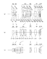
- FIG. 5 is a cross-sectional view along the optical axis showing the optical configuration at the time of the first object focusing of the zoom lens according to Example 1.
- (a) is the wide-angle end
- (b) is the middle
- (c) is the cross section at the telephoto end
- FIG. 5 is a figure for demonstrating wy7d and wy7d ' , Comprising : (a) is a figure which shows the whole zoom lens, (b) is an enlarged view which shows the image surface vicinity.
- FIG. 5 is a cross-sectional view along the optical axis showing the optical configuration at the time of the first object focusing of the zoom lens according to Example 1.
- (a) is the wide-angle end
- (b) is the middle
- (c) is the cross section at the telephoto end FIG.
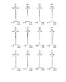
- FIG. 6 is a diagram showing spherical aberration (SA), astigmatism (AS), distortion (DT), and lateral chromatic aberration (CC) at the time of the first object focusing of the zoom lens according to Example 1; d) is an aberration diagram at the wide-angle end, (e) to (h) at the middle, and (i) to (l) at the telephoto end.
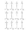
- FIG. 7 is a cross-sectional view along the optical axis showing the optical configuration at the time of the first object focusing of the zoom lens according to Example 2. (a) at the wide-angle end, (b) at the middle, (c) at the telephoto end FIG. FIGS.
- FIGS. 7A to 7C are diagrams showing spherical aberration (SA), astigmatism (AS), distortion (DT), and lateral chromatic aberration (CC) at the time of the first object focusing of the zoom lens according to Example 2.
- d) is an aberration diagram at the wide-angle end, (e) to (h) at the middle, and (i) to (l) at the telephoto end.
- FIG. 18 is a cross-sectional view along the optical axis showing the optical configuration at the time of the first object focusing of the zoom lens according to Example 3, (a) at the wide-angle end, (b) at the middle, (c) at the telephoto end FIG.
- FIG. 6A to 6C are diagrams showing spherical aberration (SA), astigmatism (AS), distortion (DT), and lateral chromatic aberration (CC) at the time of the first object focusing of the zoom lens according to Example 3.
- FIG. d) is an aberration diagram at the wide-angle end, (e) to (h) at the middle, and (i) to (l) at the telephoto end.
- FIG. 18 is a cross-sectional view along the optical axis showing the optical configuration at the time of the first object focusing of the zoom lens according to Example 4. (a) at the wide-angle end, (b) at the middle, (c) at the telephoto end FIG.
- FIG. 16 is a diagram showing spherical aberration (SA), astigmatism (AS), distortion (DT), and lateral chromatic aberration (CC) at the time of the first object focusing of the zoom lens according to Example 4; d) is an aberration diagram at the wide-angle end, (e) to (h) at the middle, and (i) to (l) at the telephoto end.
- FIG. 21 is a cross-sectional view along the optical axis showing the optical configuration at the time of the first object focusing of the zoom lens according to Example 5; (a) at the wide-angle end, (b) at the middle, (c) at the telephoto end FIG.
- 17A to 17C are diagrams showing spherical aberration (SA), astigmatism (AS), distortion (DT), and lateral chromatic aberration (CC) at the time of the first object focusing of the zoom lens according to Example 5.
- d) is an aberration diagram at the wide-angle end, (e) to (h) at the middle, and (i) to (l) at the telephoto end. It is a figure which shows a mode that the zoom imaging device of this embodiment was connected to the optical instrument.
- the zoom imaging apparatus includes a mount unit, a zoom lens that forms an image of light incident from the mount unit, and an image pickup element disposed at an image forming position, and the zoom lens sequentially operates from the image side.
- a first lens group having a positive refractive power, a second lens group having a negative refractive power, a third lens group having a positive refractive power, and a lens group having a negative refractive power The second lens group is a focus lens group, and the third lens group and a lens group having a negative refractive power located closer to the object side than the third lens group at the time of zooming from the wide-angle end to the telephoto end , And at the wide-angle end when the first object is in focus, the zoom lens is characterized by satisfying the following conditional expression (1).
- ⁇ L1 is the effective diameter of the lens surface located on the most object side of the zoom lens
- ⁇ 3GL 1 is the effective diameter of the lens surface of the third lens group located closest to the object side
- the first object is an object when the object point distance is 1000 mm
- the object point distance is the distance from the lens surface located closest to the object side of the zoom lens to the object
- the effective diameter is the maximum diameter of the range through which a ray contributing to image formation passes on the lens surface to be processed. It is.
- the zoom lens includes, in order from the image side, a first lens group having a positive refractive power, a second lens group having a negative refractive power, and a third lens group having a positive refractive power. It has a lens group and a lens group having negative refractive power.
- the second lens group is a focus lens group. Then, at the time of zooming from the wide-angle end to the telephoto end, the third lens unit and a lens unit having a negative refractive power located closer to the object side than the third lens unit move.
- the second lens group has negative refractive power.
- this second lens group By making this second lens group a focusing lens group, the refractive power of the focusing lens group becomes negative refractive power.
- the refractive power of the focusing lens group becomes negative refractive power.
- by suppressing an increase in the amount of movement of the focus lens group it is possible to suppress aberration fluctuation.
- the first lens group is disposed on the image side of the second lens group, and the refractive power of the first lens group is made positive.
- the first lens group functions as a reduction optical system, it is possible to make the first lens group smaller in aberration which fluctuates at the time of focusing. Placing a lens unit having a positive refractive power on the image side of a focusing lens unit having a negative refractive power is effective in suppressing aberration fluctuation during focusing.
- the third lens unit and a lens unit having a negative refractive power located closer to the object side than the third lens unit produce a large zooming action
- the third lens unit and a lens having this negative refractive power The group becomes the main variator.
- the change amount of the image position and the change amount of the image height due to the movement of the focus lens unit largely change according to the movement state of the main variator.
- the change of the image position and the change of the image height due to the movement of the focus lens group are greatly influenced by the movement state of the main variator.
- the focus lens group is disposed after the main variator. Therefore, since the influence of the main variator can be ignored, the focus sensitivity does not change significantly. And since the change in focus sensitivity is small, it becomes easy to control the movement of the focus lens group.
- the zoom lens configured in this way can be used as an imaging optical system for an endoscope.
- the endoscope imaging optical system When the endoscope imaging optical system is combined with the endoscope optical system, the entrance pupil position is restricted.
- the imaging optical system for endoscopes does not have the aperture stop. Therefore, the aperture of the imaging light beam is determined by the exit pupil diameter of the endoscope optical system.
- the eye point of the endoscope optical system is generally at a position where there is no problem in visual observation, for example, a position several mm from the end face of the eyepiece.
- the focus lens group is made the second lens group.
- the position of the moving lens group becomes far from the exit pupil position of the endoscope optical system.
- the refractive power of the third lens group is positive refractive power, it is possible to suppress the height of the light beam in the second lens group to a low level. As a result, it is possible to suppress the fluctuation of the aberration at the time of focusing.
- the effective diameter of the lens on the image side of the object side lens unit is made larger. Therefore, off-axis luminous flux reaching the imaging surface when the zoom lens is connected to the eyepiece It becomes easy to reduce vignetting.
- the zoom imaging device of the present embodiment satisfies the following conditional expression (2). -3.3 ⁇ f 2 / f 1 ⁇ -0.6 (2) here, f 1 is the focal length of the first lens group, f 2 is the focal length of the second lens group, It is.
- Conditional expression (2) defines the ratio between the refractive power of the first lens group and the refractive power of the second lens group.
- the refractive power of the second lens group is negative, the light beam emitted from the second lens group travels away from the optical axis.
- the conditional expression (2) it is possible to perform good correction in the first lens group with respect to the aberration generated by the light ray traveling away from the optical axis. In particular, coma aberration can be corrected well.
- conditional expression (2) By being smaller than the upper limit value of the conditional expression (2), it is possible to satisfactorily carry out aberration correction while appropriately maintaining the refractive power of the second lens unit. Moreover, falling below the upper limit value of conditional expression (2) is effective for shortening the total length of the optical system.
- conditional expression (2) it is preferable to satisfy the following conditional expression (2 ′). ⁇ 2.5 ⁇ f 2 / f 1 ⁇ 0.8 (2 ′) Furthermore, in place of the conditional expression (2), it is more preferable to satisfy the following conditional expression (2 ′ ′). -1.6 ⁇ f 2 / f 1 ⁇ -1.0 (2 '')
- the zoom imaging device of the present embodiment satisfies the following conditional expression (3). 0.55 ⁇
- ⁇ 3 (3) here, ⁇ ctw (1- ⁇ fcw x ⁇ fcw ) x ⁇ w 'x ⁇ w ', ⁇ fcw and ⁇ w 'are lateral magnifications at the wide-angle end when focusing on the first object, and ⁇ fcw is the lateral magnification of the second lens group, and ⁇ w ' is higher than that of the second lens group Lateral magnification of the lens unit located on the image side
- the first object is an object when the object point distance is 1000 mm
- the object point distance is the distance from the lens surface located closest to the object side of the zoom lens to the object, It is.
- Conditional expression (3) relates to the focus sensitivity at the wide angle end.
- the focus sensitivity is an amount that indicates the amount of movement of the image plane relative to the amount of movement of the focus lens group.
- conditional expression (3) By falling below the upper limit value of the conditional expression (3), it is possible to suppress the occurrence of astigmatism in the focus lens unit.
- conditional expression (3) it is preferable to satisfy the following conditional expression (3 ′). 0.555 ⁇
- the lens unit having negative refractive power satisfying the following conditional expression (4) be located on the object side of the lens unit having positive refractive power.
- d ng and d pg are thicknesses on the optical axis of the lens unit
- d ng is the thickness of the lens unit having the largest negative refractive power among the thicknesses of the lens units positioned closer to the object side than the second lens unit
- d pg is the thickness of the lens unit having the largest positive refractive power among the thicknesses of the lens units positioned closer to the object side than the second lens unit
- Conditional expression (4) relates to the ratio of the thicknesses on the optical axis of the two lens groups.
- One is the thickness of the predetermined positive lens group, and the other is the thickness of the predetermined negative lens group.
- the predetermined positive lens group is a lens group having the largest positive refractive power among the lens groups positioned closer to the object side than the second lens group.
- the predetermined negative lens unit is a lens unit having the largest negative refractive power among the lens units positioned closer to the object side than the second lens unit.
- Conditional expression (4) is a conditional expression for satisfactorily correcting spherical aberration while suppressing an increase in the overall length of the optical system.
- the total length of the optical system can be shortened.
- the correction of the spherical aberration can be favorably performed.
- conditional expression (4) it is preferable to satisfy the following conditional expression (4 ′). 0.15 ⁇ d ng / d pg ⁇ 0.7 (4 ') Furthermore, it is more preferable to satisfy the following conditional expression (4 ′ ′) instead of the conditional expression (4). 0.17 ⁇ d ng / d pg ⁇ 0.3 (4 '')
- the zoom imaging device of the present embodiment satisfies the following conditional expression (5).
- ⁇ fc and ⁇ L1 are effective diameters at the wide-angle end when focusing on the first object
- ⁇ fc is the maximum value of the effective diameter of the second lens group
- ⁇ L1 is the effective diameter of the lens surface located on the most object side of the zoom lens
- the first object is an object when the object point distance is 1000 mm
- the object point distance is the distance from the lens surface located closest to the object side of the zoom lens to the object
- the effective diameter is the maximum diameter of the range through which a ray contributing to image formation passes on the lens surface to be processed. It is.
- Condition (5) relates to the ratio of two effective diameters. One is the effective diameter of the second lens group, and the other is the effective diameter of the lens located closest to the object side of the zoom lens.
- conditional expression (5) By exceeding the lower limit value of conditional expression (5), enlargement of the object side lens unit can be prevented. As described above, exceeding the lower limit of conditional expression (5) is advantageous for downsizing of the optical system. As a result, it is possible to perform good correction of spherical aberration while achieving downsizing of the optical system.
- conditional expression (5) it is possible to correct spherical aberration and coma aberration in the focus lens group while preventing enlargement of the focus lens group.
- conditional expression (5) it is preferable to satisfy the following conditional expression (5 ′). 1 ⁇ fc / ⁇ L1 ⁇ 2.5 (5 ′) Furthermore, it is more preferable to satisfy the following conditional expression (5 ′ ′) in place of the conditional expression (5). 1.1 ⁇ fc / ⁇ L1 ⁇ 2 (5 '')
- the zoom imaging device of the present embodiment satisfies the following conditional expression (6). ⁇ 5 ⁇ f 2 / f Lw ⁇ 0.4 (6) here, f 2 is the focal length of the second lens group, f Lw is the focal length at the wide-angle end of the zoom lens when focused on the first object, The first object is an object when the object point distance is 1000 mm, The object point distance is the distance from the lens surface located closest to the object side of the zoom lens to the object, It is.
- Condition (6) takes the ratio of two focal lengths. One is the focal length of the second lens group, and the other is the focal length of the zoom lens.
- the focal length of the zoom lens is the focal length at the wide angle end when the first object is in focus.
- conditional expression (6) is effective for shortening the total length of the optical system, and this makes it possible to reduce the amount of movement of the second lens group.
- conditional expression (6) it is preferable to satisfy the following conditional expression (6 ′). -3 ⁇ f 2 / f Lw ⁇ -0.8 (6 ') Furthermore, in place of the conditional expression (6), it is more preferable to satisfy the following conditional expression (6 ′ ′). -2.4 ⁇ f 2 / f Lw ⁇ -1.5 (6 '')
- the zoom imaging device of the present embodiment satisfies the following conditional expression (7). 1 ⁇ f 1 / f Lw ⁇ 3.5 (7) here, f 1 is the focal length of the first lens group, f Lw is the focal length at the wide-angle end of the zoom lens when focused on the first object, The first object is an object when the object point distance is 1000 mm, The object point distance is the distance from the lens surface located closest to the object side of the zoom lens to the object, It is.
- Condition (7) takes the ratio of two focal lengths.
- One is the focal length of the first lens group, and the other is the focal length of the zoom lens.
- the focal length of the zoom lens is the focal length at the wide angle end when the first object is in focus.
- the first lens group good correction can be performed on the aberration generated by the off-axis ray. Also, giving the first lens group appropriate refractive power is effective for shortening the total length of the optical system.
- conditional expression (7) By exceeding the lower limit value of the conditional expression (7), the coma aberration can be corrected well. Below the upper limit value of the conditional expression (7), shortening of the total length of the optical system can be achieved.
- conditional expression (7) it is preferable to satisfy the following conditional expression (7 ′). 1 ⁇ f 1 / f Lw ⁇ 3 (7 ') Furthermore, it is more preferable to satisfy the following conditional expression (7 ′ ′) instead of the conditional expression (7). 1.2 ⁇ f 1 / f Lw ⁇ 2.2 (7 '')
- the zoom imaging device of the present embodiment satisfies the following conditional expression (8). -6 ⁇ f ng / f pg ⁇ -0.5 (8) here, f ng is the focal length of the lens unit having the largest negative refracting power among the focal lengths of the lens units positioned on the object side of the second lens unit, f pg is the focal length of the lens unit having the largest positive refracting power among the focal lengths of the lens units positioned on the object side of the second lens unit, It is.
- Condition (8) relates to the ratio of focal lengths of the two lens groups.
- One is a focal length of a predetermined negative lens group, and the other is a focal length of a predetermined positive lens group.
- the predetermined negative lens unit is a lens unit having the largest negative refractive power among the lens units positioned closer to the object side than the second lens unit.
- the predetermined positive lens group is a lens group having the largest positive refractive power among the lens groups positioned closer to the object side than the second lens group.
- conditional expression (8) it is possible to balance the refracting power of the predetermined negative lens group and the refracting power of the predetermined positive lens group.
- the Petzval sum can be set well, astigmatism can be corrected well. Thereby, it is possible to maintain good optical performance.
- conditional expression (8) it is preferable to satisfy the following conditional expression (8 ′). -5 ⁇ f ng / f pg ⁇ -0.9 (8 ') Furthermore, in place of the conditional expression (8), it is more preferable to satisfy the following conditional expression (8 ′ ′). -3.5 ⁇ f ng / f pg ⁇ -1.4 (8 '')
- ⁇ ctt (1 ⁇ fct ⁇ ⁇ fct ) ⁇ ⁇ t ′ ⁇ ⁇ t ′
- ⁇ ctw (1- ⁇ fcw x ⁇ fcw ) x ⁇ w 'x ⁇ w ', ⁇ fct and ⁇ t 'are lateral magnifications at the telephoto end when focusing on the first object
- ⁇ fct is the lateral magnification of the second lens group
- ⁇ t ' is more than that of the second lens group
- Conditional expression (9) relates to the ratio of the focus sensitivity at the telephoto end to the focus sensitivity at the wide angle end.
- the focus sensitivity is an amount that indicates the amount of movement of the image plane relative to the amount of movement of the focus lens group.
- conditional expression (9) When conditional expression (9) is satisfied, fluctuations in focus sensitivity can be suppressed at both the telephoto end and the wide-angle end. As described above, since the change in focus sensitivity is small, the amount of movement of the image plane with respect to the amount of movement of the focus lens unit does not largely change depending on the state. Therefore, it becomes easy to control the movement of the focus lens group.
- conditional expression (9 ′) it is preferable to satisfy the following conditional expression (9 ′). 0.8 ⁇
- the zoom imaging device of the present embodiment satisfies the following conditional expression (10). 0.08 ⁇ L1 / f Lt ⁇ 0.9 (10) here, ⁇ L1 is the effective diameter of the lens surface located on the most object side of the zoom lens, and the effective diameter at the wide-angle end when the first object is in focus, f Lt is the focal length at the telephoto end of the zoom lens when focused on the first object,
- the first object is an object when the object point distance is 1000 mm
- the object point distance is the distance from the lens surface located closest to the object side of the zoom lens to the object,
- the effective diameter is the maximum diameter of the range through which a ray contributing to image formation passes on the lens surface to be processed. It is.
- Conditional expression (10) takes the ratio of the effective diameter of the lens located closest to the object side of the zoom lens to the focal length at the telephoto end of the zoom lens when focused on the first object.
- the effective diameter of the lens located closest to the object side of the zoom lens can be reduced, so that downsizing of the optical system can be achieved.
- conditional expression (10) it is preferable to satisfy the following conditional expression (10 ′). 0.10 ⁇ L1 / f Lt ⁇ 0.5 (10 ') Furthermore, it is more preferable to satisfy the following conditional expression (10 ′ ′) instead of the conditional expression (10). 0.12 ⁇ L1 / f Lt ⁇ 0.25 (10 '')
- the zoom imaging device of the present embodiment satisfies the following conditional expression (11). ⁇ 5 ⁇ (r lf + r lb ) / (r lf ⁇ r lb ) ⁇ 0.01 (11) here, r lf is the radius of curvature of the object-side lens surface of the lens closest to the image side, r lb is the radius of curvature of the image-side lens surface of the lens closest to the image side, It is.
- Conditional expression (11) relates to the shape of the lens located closest to the image side.
- conditional expression (11) By exceeding the lower limit value of the conditional expression (11), astigmatism can be corrected well. As a result, it is possible to maintain good optical performance. By falling below the upper limit value of the conditional expression (11), spherical aberration can be corrected well. As a result, it is possible to maintain good optical performance.
- conditional expression (11 ′) be satisfied instead of the conditional expression (11).
- -3 ⁇ (r lf + r lb ) / (r lf -r lb ) ⁇ -0.01 (11 ')
- the third lens group preferably includes a positive lens disposed closest to the object side and a cemented lens disposed closest to the image side.
- the entrance pupil position is restricted.
- the imaging optical system for endoscopes does not have the aperture stop. Therefore, the aperture of the imaging light beam is determined by the exit pupil diameter of the endoscope optical system.
- the eye point of the endoscope optical system is generally at a position where there is no problem in visual observation, for example, a position several mm from the end face of the eyepiece.
- a light beam incident on the third lens group is diverged by a lens group having a negative refractive power located closer to the object side than the third lens group. Since the height of the axial ray in the third lens group becomes high, it becomes difficult to correct spherical aberration. Therefore, a positive lens having air contact surfaces on both sides is disposed closest to the object side. This enables bending at the two air contact surfaces, so that spherical aberration can be corrected well. Further, axial chromatic aberration can be well corrected by arranging the cemented lens most on the image side.
- At least one cementing surface of negative refractive power may be provided in the third lens group. In this way, astigmatism can be corrected well.
- the first lens group preferably includes a positive lens disposed closest to the object side and a negative lens disposed closest to the image side.
- the first lens group is a lens group disposed closest to the image side in the zoom lens.
- the first lens group by arranging the lenses in order of the positive lens and the negative lens from the object side, it is possible to diverge the light ray converged by the positive lens by the negative lens. As a result, it is possible to make the angle of the light beam passing through the final lens group gentle with respect to the optical axis. Therefore, in particular, the occurrence of off-axis aberration can be suppressed.
- the zoom imaging device of the present embodiment satisfies the following conditional expression (12). -4 ⁇ ( r2Gff + r2Gfb ) / ( r2Gff -r2Gfb ) ⁇ 2.5 (12) here, r 2 Gff is the radius of curvature of the object-side lens surface of the lens located closest to the object in the second lens group, r 2 G fb is the radius of curvature of the image-side lens surface of the lens located closest to the image side in the second lens group, It is.
- Conditional expression (12) relates to the shape of the focus lens group.
- the shape of the focus lens group becomes a shape suitable for correction of spherical aberration. Therefore, the variation of the spherical aberration at the time of focusing can be suppressed.
- conditional expression (12 ′) be satisfied instead of the conditional expression (12).
- -3.5 ⁇ ( r2Gff + r2Gfb ) / ( r2Gff -r2Gfb ) ⁇ 2 (12 ')
- -3 ⁇ ( r2Gff + r2Gfb ) / ( r2Gff -r2Gfb ) ⁇ 1 (12 '')
- the zoom imaging apparatus of the present embodiment includes a mount unit, a zoom lens that forms an image of light incident from the mount unit, and an image pickup device disposed at an image forming position, and the zoom lens is on the image side
- the second lens group is a focusing lens group, and the third lens group and the fourth moving lens group during zooming from the wide-angle end to the telephoto end , And the first lens group, the second lens group, and the fifth lens group are fixed.
- the zoom lens includes, in order from the image side, a first lens group having a positive refractive power, a second lens group having a negative refractive power, and a third lens group having a positive refractive power. It is comprised from a lens group, the 4th lens group which has negative refractive power, and the 5th lens group which has negative refractive power (henceforth "the 1st composition").
- the zoom imaging apparatus of the present embodiment includes a mount unit, a zoom lens that forms an image of light incident from the mount unit, and an image pickup device disposed at an image forming position, and the zoom lens is on the image side
- a first lens group having a positive refractive power a second lens group having a negative refractive power
- a third lens group having a positive refractive power a fourth lens group having a negative refractive power
- the second lens group is a focus lens group
- the third lens group and the fourth moving lens group move at the time of zooming from the wide-angle end to the telephoto end
- the group is characterized by being fixed.
- the zoom lens includes, in order from the image side, a first lens group having a positive refractive power, a second lens group having a negative refractive power, and a third lens group having a positive refractive power. It is comprised from the lens group and the 4th lens group which has negative refractive power (henceforth "the 2nd composition").
- Both the zoom lens of the first configuration and the zoom lens of the second configuration can be used as an imaging optical system for an endoscope.
- the endoscope imaging optical system When the endoscope imaging optical system is combined with the endoscope optical system, the entrance pupil position is restricted.
- the imaging optical system for endoscopes does not have the aperture stop. Therefore, the aperture of the imaging light beam is determined by the exit pupil diameter of the endoscope optical system.
- the eye point of the endoscope optical system is generally at a position where there is no problem in visual observation, for example, a position several mm from the end face of the eyepiece.
- the focus lens group is made the second lens group. In this way, the position of the focus lens group can be moved away from the entrance pupil position, so the height of the light beam incident on the focus lens group can be reduced. As a result, it is possible to suppress an increase in aberration fluctuation when the focus lens unit moves.
- the refractive power of the focus lens group is negative, the focus sensitivity can be increased. As a result, it is possible to suppress an increase in the amount of movement of the focus lens group at the time of focusing.
- the first lens group having positive refractive power is disposed on the image side of the focus lens group (second lens group).
- a lens group having positive refractive power is disposed following a lens group having negative refractive power (focus lens group). Therefore, it is possible to suppress the change in the angle of view at the time of focusing.
- the movement of the lens unit in each configuration is as follows. In the first configuration, only the third lens unit and the fourth lens unit move, and the first lens unit, the second lens unit, and the fifth lens unit are fixed. In the second configuration, only the third lens unit and the fourth lens unit move, and the first lens unit and the second lens unit are fixed.
- the third lens unit and the fourth lens unit produce a large zooming action, the third lens unit and the fourth lens unit become main variators.
- the change amount of the image position and the change amount of the image height due to the movement of the focus lens unit largely change according to the movement state of the main variator.
- the change of the image position and the change of the image height due to the movement of the focus lens group are greatly influenced by the movement state of the main variator.
- the focus lens unit is the second lens unit.
- the focus lens group is disposed after the main variator. Therefore, since the influence of the main variator can be ignored, the focus sensitivity does not change significantly. And since the change in focus sensitivity is small, it becomes easy to control the movement of the focus lens group.
- the lens diameter can be reduced in the second lens unit and the fourth lens unit. Therefore, by moving the second lens unit and the fourth lens unit, the optical system can be miniaturized. Further, by setting the number of lens units to be moved at the time of zooming to be two, control of movement of the lens units and mechanical configuration can be relatively simplified.
- the zoom imaging apparatus of the present embodiment includes a mount unit, a zoom lens that forms an image of light incident from the mount unit, and an image pickup device disposed at an image forming position, and the zoom lens is on the image side
- the second lens group is a focusing lens group, and has a third lens group and a lens having a negative refractive power located closer to the object side than the third lens group at the time of zooming from the wide-angle end to the telephoto end.
- the group is moved, and the following conditional expression (13) is satisfied.
- the mount side is the object side
- the imaging device side is the image side
- y w7 d and y w 7 d ′ are the ray heights of the predetermined ray at the position where the predetermined ray intersects the image plane
- y w 7 d is the ray height in the state focused on the first object
- y w 7 d ′ is Ray height in defocused state
- the predetermined light beam is a light beam having a field angle
- any zoom lens used in the zoom imaging device of the present embodiment can be used as an imaging optical system for an endoscope.
- the endoscope imaging optical system When the endoscope imaging optical system is combined with the endoscope optical system, the entrance pupil position is restricted.
- the imaging optical system for endoscopes does not have the aperture stop. Therefore, the aperture of the imaging light beam is determined by the exit pupil diameter of the endoscope optical system.
- the eye point of the endoscope optical system is generally at a position where there is no problem in visual observation, for example, a position several mm from the end face of the eyepiece.
- the position of the focus lens unit is far from the entrance pupil position.
- the refractive power of the third lens group is positive refractive power, it is possible to suppress the height of rays in the focus lens group to a low level. As a result, aberration variation due to focusing can be suppressed.
- the refractive power of the focus lens group is negative, the focus sensitivity can be increased. As a result, it is possible to suppress an increase in the amount of movement of the focus lens group at the time of focusing.
- a first lens group having positive refractive power is disposed on the image side of the focus lens group (second lens group).
- a lens group having positive refractive power is disposed following the lens group having negative refractive power (focus lens group). Therefore, it is possible to suppress the change in the angle of view at the time of focusing.
- the third lens group and the fourth lens group produce a large zooming action
- the third lens group and the fourth lens group become main variators.
- the change amount of the image position and the change amount of the image height due to the movement of the focus lens unit largely change according to the movement state of the main variator.
- the change of the image position and the change of the image height due to the movement of the focus lens group are greatly influenced by the movement state of the main variator.
- the focus lens group is disposed after the main variator. Therefore, since the influence of the main variator can be ignored, the focus sensitivity does not change significantly. And since the change in focus sensitivity is small, it becomes easy to control the movement of the focus lens group.
- Conditional expression (13) relates to the amount of change in image height.
- the y w7 d and y w7 d ′ in the conditional expression (13) will be described with reference to FIG.
- FIG. 1 (a) is a diagram showing the entire zoom lens, and (b) is an enlarged view showing the vicinity of an image plane.
- L w7 represents a predetermined light ray
- LA represents a lens closest to the object side of the zoom lens
- Fo represents a focus lens group.
- FIG. 1 is a view showing how the image height is changed by the movement of the focus lens group Fo.
- P1 is the position of the focus lens group Fo in a state in which the first object is focused.
- P2 is a position at which the focus lens group Fo is moved by a small amount ⁇ S. The movement of the focusing lens unit Fo is drawn in an exaggerated manner in FIG.
- the predetermined light beam L w7 is a light beam with a field angle of 7 degrees at the wide angle end.
- the predetermined light beam L w7 passes through the center of the object-side lens surface of the lens LA.
- the focus lens unit Fo is caused to perform the wobbling operation. Thereby, the focus lens group Fo moves to the position of P2.
- the light beam incident on the focus lens group Fo travels as shown by a broken line and reaches the image position.
- the image height at this time is y w7 d ' .
- the image height varies between y w7 d and y w7 d ′ according to the position of the focus lens group Fo.
- the focus lens unit Fo performs a wobbling operation to keep the in-focus state constantly. Therefore, in auto focusing, it is required that the amount of change in image height be small when the focus lens group Fo moves.
- Conditional expression (13) indicates how much the change of the image height is noticeable on the image pickup element when the focus lens group slightly changes. Since the amount of change in image height is divided by the pixel pitch, the finer the pixel pitch, the more noticeable the change in image height. Further, in the case of the same sensor size, the larger the total number of pixels, the finer the pixel pitch. Therefore, the conditional expression (13) reflects that the change in the image height is more noticeable as the number of pixels of the imaging device is larger.
- conditional expression (13 ) it is preferable to satisfy the following conditional expression (13 ′).
- conditional expression (13 ′ ′) instead of the conditional expression (13).
- the zoom lens used in the zoom imaging device according to the present invention will be described in detail based on the drawings.
- the present invention is not limited by this embodiment.
- the positive and negative refractive powers are based on the paraxial radius of curvature.
- the zoom lens of each of the following embodiments is connected to the eyepiece of the optical device at the time of use. Since the aperture stop is usually arranged in the optical system on the optical device side, the aperture stop is not provided on the zoom lens side. However, in order to design a zoom lens, an aperture stop is required.
- the virtual stop in the following description of the embodiment is an aperture stop provided for design. Thus, in an actual zoom lens, the aperture stop does not physically exist. However, a stop (for example, a flare stop) for blocking unnecessary light rays may be disposed at the position of the virtual stop.
- the position of the first object is a position when the object point distance is 1000 mm.
- the position of the second object is a position when the object point distance is 333.33 mm, and the object is closest to the zoom lens at the position of the second object.
- FIG. 2 is a cross-sectional view (lens cross-sectional view) along the optical axis showing the optical configuration at the time of the first object focusing of the zoom lens of Example 1, wherein (a) is a cross-sectional view at the wide angle end; ) Is a cross-sectional view in the intermediate focal length state, and (c) is a cross-sectional view at the telephoto end.
- F indicates a filter
- CG indicates a cover glass
- I indicates an imaging surface (image surface) of the imaging device.
- CG represents not a cover glass but a color separation prism.
- FIG. 3 is an aberration diagram of the zoom lens according to Example 1 when the first object is in focus.
- ⁇ is a half angle of view.
- the symbols in the aberration diagrams are common to the examples described later.
- (a), (b), (c) and (d) respectively indicate spherical aberration (SA), astigmatism (AS), distortion (DT) and magnification at the wide angle end.
- SA spherical aberration
- AS astigmatism
- DT distortion
- CC magnification at the wide angle end.
- SA spherical aberration
- AS astigmatism
- DT distortion
- CC lateral chromatic aberration
- (i), (j), (k) and (l) indicate spherical aberration (SA), astigmatism (AS), distortion (DT) and lateral chromatic aberration (CC) at the telephoto end, respectively. ing.
- the first lens unit is located closest to the image side, but each lens unit will be described from the lens unit on the object side.
- the other embodiments are similar.
- FIG. 2 is a cross-sectional view along an optical axis showing an optical configuration at the time of first object focusing of the zoom lens of Example 1.
- FIG. 3 is an aberration diagram of the zoom lens of Example 1 when the first object is in focus.
- a fifth lens group G5 having negative refractive power, a fourth lens group G4 having negative refractive power, and a positive refractive power are sequentially arranged from the object side.
- a second lens group G2 having a negative refractive power, and a first lens group G1 having a positive refractive power are sequentially arranged from the object side.
- the fifth lens group G5 is composed of a positive meniscus lens L1 having a convex surface facing the image side and a negative meniscus lens L2 having a convex surface facing the image side.
- the positive meniscus lens L1 and the negative meniscus lens L2 are cemented.
- the virtual stop is set on the image side of the negative meniscus lens L2.
- the fourth lens group G4 is composed of a biconcave negative lens L4 and a positive meniscus lens L5 having a convex surface directed to the object side.
- the biconcave negative lens L4 and the positive meniscus lens L5 are cemented.
- the third lens group G3 has a positive meniscus lens L5 having a convex surface on the image side, a biconvex positive lens L6, a biconcave negative lens L7, a negative meniscus lens L8 having a convex surface on the object side, and And a positive meniscus lens L9 having a convex surface.
- the biconvex positive lens L6 and the biconcave negative lens L7 are cemented.
- the negative meniscus lens L8 and the positive meniscus lens L9 are cemented.
- the second lens group G2 is composed of a biconcave negative lens L10 and a positive meniscus lens L11 with a convex surface facing the object side.
- the biconcave negative lens L10 and the positive meniscus lens L11 are cemented.
- the first lens group G1 is composed of a biconvex positive lens L12, a negative meniscus lens L13 having a convex surface facing the image side, and a negative meniscus lens L14 having a convex surface facing the image side.
- the biconvex positive lens L12 and the negative meniscus lens L13 are cemented.
- the fifth lens group G5 is fixed, the fourth lens group G4 moves to the image side, and then moves to the object side, and the third lens group G3 moves to the object side
- the second lens group G2 is fixed, and the first lens group G1 is fixed.
- focusing on the subject is performed by the movement of the second lens group G2.
- the biconcave negative lens L10 and the positive meniscus lens L11 move to the image side.
- FIG. 4 is a cross-sectional view along an optical axis showing an optical configuration at the time of first object focusing of the zoom lens of Example 2.
- FIG. 5 is an aberration diagram of the zoom lens of Example 2 when the first object is in focus.
- a fifth lens group G5 having negative refractive power, a fourth lens group G4 having negative refractive power, and a positive refractive power are sequentially arranged from the object side.
- a second lens group G2 having a negative refractive power, and a first lens group G1 having a positive refractive power are sequentially arranged from the object side.
- the fifth lens group G5 is composed of a positive meniscus lens L1 having a convex surface facing the image side and a negative meniscus lens L2 having a convex surface facing the image side.
- the positive meniscus lens L1 and the negative meniscus lens L2 are cemented.
- the virtual stop is set on the image side of the negative meniscus lens L2.
- the fourth lens group G4 is composed of a biconcave negative lens L4 and a positive meniscus lens L5 having a convex surface directed to the object side.
- the biconcave negative lens L4 and the positive meniscus lens L5 are cemented.
- the third lens group G3 includes a biconvex positive lens L5, a biconvex positive lens L6, a biconcave negative lens L7, a negative meniscus lens L8 having a convex surface on the object side, and a positive meniscus having a convex surface on the object side It consists of a lens L9.
- the biconvex positive lens L6 and the biconcave negative lens L7 are cemented.
- the negative meniscus lens L8 and the positive meniscus lens L9 are cemented.
- the second lens group G2 is composed of a positive meniscus lens L10 with a convex surface facing the image side and a negative meniscus lens L11 with a convex surface facing the image side.
- the first lens group G1 is composed of a biconvex positive lens L12 and a negative meniscus lens L13 having a convex surface directed to the image side.
- the fifth lens group G5 is fixed, the fourth lens group G4 moves to the image side, and then moves to the object side, and the third lens group G3 moves to the object side
- the second lens group G2 is fixed, and the first lens group G1 is fixed.
- focusing on the subject is performed by the movement of the fourth lens group G4.
- the positive meniscus lens L10 and the negative meniscus lens L11 move to the image side.
- FIG. 6 is a cross-sectional view along an optical axis showing an optical configuration at the time of first object focusing of the zoom lens of Example 3.
- FIG. 7 is an aberration drawing of the zoom lens of Example 3 in focusing on the first object.
- a fourth lens group G4 having a negative refractive power, a third lens group G3 having a positive refractive power, and a negative refractive power are sequentially arranged from the object side.
- a first lens group G1 having a positive refractive power is sequentially arranged from the object side.
- the fourth lens group G4 is composed of a negative meniscus lens L1 having a convex surface directed to the image side, a positive meniscus lens L2 having a convex surface directed to the image side, and a biconcave negative lens L3.
- the negative meniscus lens L1, the positive meniscus lens L2, and the biconcave negative lens L3 are cemented.
- the virtual stop is set on the object side of the negative meniscus lens L1.
- the third lens group G3 is composed of a biconvex positive lens L4, a biconvex positive lens L5, a biconcave negative lens L6, a negative meniscus lens L7 having a convex surface facing the object side, and a biconvex positive lens L8.
- the biconvex positive lens L5 and the biconcave negative lens L6 are cemented.
- the negative meniscus lens L7 and the biconvex positive lens L8 are cemented.
- the second lens group G2 is composed of a biconcave negative lens L9.
- the first lens group G1 is composed of a biconvex positive lens L10 and a biconcave negative lens L11.
- the fourth lens group G4 moves to the image side, then moves to the object side, the third lens group G3 moves to the object side, and the second lens group G2 is fixed.
- the first lens group G1 is fixed.
- the biconcave negative lens L9 moves to the image side.
- Aspheric surfaces are provided on a total of six surfaces: both surfaces of the biconvex positive lens L4, both surfaces of the biconcave negative lens L9, and both surfaces of the biconvex positive lens L10.
- FIG. 8 is a cross-sectional view along an optical axis showing an optical configuration at the time of the first object focusing of the zoom lens of Example 4.
- FIG. 9 is an aberration diagram of the zoom lens of Example 4 when the first object is in focus.
- a fourth lens group G4 having negative refractive power, a third lens group G3 having positive refractive power, and a negative refractive power are sequentially arranged from the object side.
- a first lens group G1 having a positive refractive power is sequentially arranged from the object side.
- the fourth lens group G4 is composed of a negative meniscus lens L1 having a convex surface directed to the image side, a positive meniscus lens L2 having a convex surface directed to the image side, and a biconcave negative lens L3.
- the negative meniscus lens L1, the positive meniscus lens L2, and the biconcave negative lens L3 are cemented.
- the virtual stop is set on the object side of the negative meniscus lens L1.
- the third lens group G3 is composed of a biconvex positive lens L4, a biconvex positive lens L5, a biconcave negative lens L6, a negative meniscus lens L7 having a convex surface facing the object side, and a biconvex positive lens L8.
- the biconvex positive lens L5 and the biconcave negative lens L6 are cemented.
- the negative meniscus lens L7 and the biconvex positive lens L8 are cemented.
- the second lens group G2 is composed of a biconcave negative lens L9.
- the first lens group G1 is composed of a biconvex positive lens L10, a biconvex positive lens L11, and a biconcave negative lens L12.
- the fourth lens group G4 moves to the image side, then moves to the object side, the third lens group G3 moves to the object side, and the second lens group G2 is fixed.
- the first lens group G1 is fixed.
- the biconcave negative lens L9 moves to the image side.
- FIG. 10 is a cross-sectional view along an optical axis showing an optical configuration at the time of the first object focusing of the zoom lens of Example 5.
- FIG. 11 is an aberration drawing of the zoom lens of Example 5 when the first object is in focus.
- the zoom lens according to Example 5 includes, in order from the object side, a fourth lens group G4 having negative refractive power, a third lens group G3 having positive refractive power, and a negative refractive power. And a first lens group G1 having a positive refractive power.
- the fourth lens group G4 is composed of a negative meniscus lens L1 having a convex surface directed to the image side, a positive meniscus lens L2 having a convex surface directed to the image side, and a biconcave negative lens L3.
- the negative meniscus lens L1, the positive meniscus lens L2, and the biconcave negative lens L3 are cemented.
- the virtual stop is set on the object side of the negative meniscus lens L1.
- the third lens group G3 includes a biconvex positive lens L4, a positive meniscus lens L5 having a convex surface on the object side, a negative meniscus lens L6 having a convex surface on the object side, and a negative meniscus lens having a convex surface on the object side It comprises L7 and a biconvex positive lens L8.
- the positive meniscus lens L5 and the negative meniscus lens L6 are cemented.
- the negative meniscus lens L7 and the biconvex positive lens L8 are cemented.
- the second lens group G2 is composed of a biconcave negative lens L9.
- the first lens group G1 is composed of a biconvex positive lens L10 and a negative meniscus lens L11 having a convex surface directed to the image side.
- the fourth lens group G4 moves to the image side, then moves to the object side, the third lens group G3 moves to the object side, and the second lens group G2 is fixed.
- the first lens group G1 is fixed.
- the biconcave negative lens L9 moves to the image side.
- r 1, r 2,... Are the radius of curvature of each lens surface
- d 1, d 2,... Are the thicknesses or air gaps of each lens
- nd 1, nd 2,. .. Are the Abbe numbers of the respective lenses
- ER is the effective diameter
- * marks are aspheric surfaces.
- f is the focal length of the entire zoom lens system
- FB is a back focus
- IH is an image height
- ⁇ is a half angle of view
- f1, f2... Are focal lengths of the respective lens units.
- the total length is obtained by adding the back focus to the distance from the lens front surface to the lens final surface.
- the back focus is the air conversion of the distance from the lens final surface to the paraxial image surface.
- the wide angle 1, the middle 1 and the telephoto 1 are respectively a wide angle end, an intermediate focal length state and a telephoto end in a state in which the first object is in focus.
- the wide angle 2, middle 2 and telephoto 2 are respectively a wide angle end, an intermediate focal length state and a telephoto end in a state in which the second object is in focus.
- the values of IH and ⁇ are not values at the focal length of each state.
- the aspheric surface shape is expressed by the following equation, assuming that the optical axis direction is z and the direction orthogonal to the optical axis is y, the conical coefficient is k, and the aspheric coefficient is A4, A6, A8, and A10. .
- z (y 2 / r) / [1 + ⁇ 1-(1 + k) (y / r) 2 ⁇ 1/2 ] + A4y 4 + A6y 6 + A8y 8 + A10y 10
- “e ⁇ n” (n is an integer) indicates “10 ⁇ n ”.
- the symbols of these specification values are common to the numerical data of the embodiments described later.
- Numerical embodiment 4 Unit mm Plane data Plane number r d nd dd ER Object ⁇ ⁇ 1 ⁇ ⁇ variable 2 -13.458 0.70 1.65160 58.55 2.6317 3-28.440 1.68 2.00330 28.27 2.7626 4-9.419 0.70 1.74400 44.78 2.9604 5 72.451 Variable 3.1106 6 77.090 2.50 1.88300 40.76 6.1987 7-37.883 0.30 6.3526 8 20.290 3.66 1.88300 40.76 6.3884 9-20.984 0.70 2.00330 28.27 6.1423 10 133.018 0.50 5.9413 11 34.761 0.70 1.80518 25.42 5.7814 12 10.000 3.20 1.49700 81.61 5.4534 13 -95.858 Variable 5.3292 14 -26.653 0.70 1.49700 81.61 4.9066 15 46.021 Variable 4.848 16 15.796 2.98 1.88300 40.76 4.7269 17-27.199 0.65 4.4424
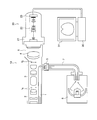
- FIG. 12 shows how the zoom imaging apparatus of the present embodiment is connected to an optical device.
- FIG. 12 shows the case where the optical instrument is a rigid endoscope.
- the rigid endoscope 10 includes a scope-side light guide 1, an objective lens 2, a relay lens 3, an eyepiece lens 4, and an optical element 5.
- An eyepiece 4 is disposed in the eyepiece 6 of the rigid endoscope 10. Further, the light source device 8 is connected to the rigid endoscope 10 via the light guide cable 7.
- the light emitted from the light source device 8 is transmitted to the incident portion of the scope-side light guide 1 by the light guide cable 7.
- the light guide cable 7 and the scope-side light guide 1 are directly connected or connected via the optical element 5.
- the optical element 5 is an element that converts the NA of light emitted from the light guide cable 7.
- the illumination light that has entered the scope-side light guide 1 is transmitted to the tip of the rigid endoscope 10. Illumination light is emitted from the tip of the rigid endoscope 10 to the subject.
- a subject image I 1 is formed by the objective lens 2.
- Subject image I 1 is relayed by the relay lens 3, the object image I 2 to a predetermined position is formed.
- the user can visually observe the subject through the eyepiece 6.
- the zoom imaging device 20 of the present embodiment is connected to the eyepiece unit 6.
- the zoom imaging device 20 includes a mount unit 21, a zoom lens 22, and an imaging device 23.
- the zoom lens of Embodiment 1 is used as the zoom lens 22.
- the zoom lens of Embodiment 1 is an optical system suitable for a system (three-plate type) for imaging using three imaging devices, and therefore a prism is disposed in front of the imaging device 23.
- a screw type mount, a bayonet type mount, or the like is used as the mount portion 21 .
- the rigid endoscope 10 and the zoom imaging device 20 can be connected to the eyepiece 6 by using a screw type mount, a bayonet type mount, or the like.
- the rigid endoscope 10 By connecting the rigid endoscope 10 and the zoom imaging device 20, light from the subject is incident on the zoom lens 22 from the eyepiece 4 through the mount unit 21.
- the light incident on the zoom lens 22 is imaged by the zoom lens 22 to form an image of an object at the imaging position. Since the imaging device 23 is disposed at the imaging position, a subject image is captured by the imaging device 23. In this way, the image of the subject can be acquired.
- the image of the subject is sent to the processing device 30.
- various processes are performed as needed.
- the image of the subject is finally displayed on the television monitor 31.
- the side corresponding to the upper part of the device in the peripheral portion of the observed image may be configured to be an image that is recessed inward.
- a projection may be provided on a part of the aperture of the field stop in the rigid endoscope.
- the same effect can be obtained by devising the arrangement of fiber bundles.
- a field stop of the same shape may be used.
- the arrangement of the bundle may be configured such that the side corresponding to the upper part of the peripheral part of the observed image is an image that is recessed inward. The relationship between the image obtained by the light beam passing through the eyepiece and the upper part of the device can be easily understood.
- the size of the subject image I 2 is determined by the objective lens 2 and the relay lens 3. Therefore, in the zoom imaging device 20, an image of a predetermined size is formed on the imaging element 23 by the zoom lens 22. Therefore, the size of the image formed on the imaging device 23 changes according to the magnification of the zoom lens.
- the size of the light receiving surface of the imaging device 23 is constant, an image larger than the light receiving surface is formed on the light receiving surface of the imaging device 23 at the telephoto end. In this case, since a part of the subject image I 2 is captured, the image obtained by enlarging a part of the subject is acquired.
- the object image I 2 is formed to fit the width of the long side of the light-receiving surface.
- the entire image of the subject is acquired.
- the image displayed on the television monitor 31 is an image with missing corners, for example, an oblong image with an outer shape.
- the zoom lens of the present embodiment is used as the zoom lens 22.
- an image of the size desired by the user can be obtained.
- the variation of the image height is small at the time of focusing, it is possible to always obtain an image without discomfort even in the state where the auto focusing is operated.
- the present invention is suitable for a zoom imaging apparatus in which the occurrence of on-axis aberration is sufficiently suppressed and the variation in spherical aberration at the time of focusing is small.
Landscapes
- Physics & Mathematics (AREA)
- General Physics & Mathematics (AREA)
- Optics & Photonics (AREA)
- Lenses (AREA)
- Instruments For Viewing The Inside Of Hollow Bodies (AREA)
- Nonlinear Science (AREA)
Abstract
L'invention concerne un dispositif d'imagerie à zoom comprenant une section de montage 21, un zoom 22 permettant de former une image de lumière qui pénètre à partir de la section de montage 21, et un élément d'imagerie 23 agencé dans une position de formation d'image. Le zoom 22 comprend, dans l'ordre depuis le côté image, un premier groupe d'objectifs G1 présentant une réfringence positive, un deuxième groupe d'objectifs G2 présentant une réfringence négative, un troisième groupe d'objectifs G3 présentant une réfringence positive, et un groupe d'objectifs présentant une réfringence négative. Le deuxième groupe d'objectifs G2 consiste en un groupe d'objectifs de mise au point. Le dispositif d'imagerie à zoom est caractérisé en ce que, lorsque l'agrandissement varie de l'extrémité grand angulaire à l'extrémité téléobjectif, le troisième groupe d'objectifs G3 et le groupe d'objectifs présentant une réfringence négative et qui est positionné plus loin du côté objet que le troisième groupe d'objectifs se déplacent et satisfont l'expression conditionnelle (1) suivante : φL1 < φ3GL1.
Priority Applications (3)
| Application Number | Priority Date | Filing Date | Title |
|---|---|---|---|
| PCT/JP2015/053640 WO2016129054A1 (fr) | 2015-02-10 | 2015-02-10 | Dispositif d'imagerie à zoom |
| JP2016574551A JP6503383B2 (ja) | 2015-02-10 | 2015-02-10 | ズーム撮像装置 |
| US15/674,418 US10338342B2 (en) | 2015-02-10 | 2017-08-10 | Zoom image pickup apparatus |
Applications Claiming Priority (1)
| Application Number | Priority Date | Filing Date | Title |
|---|---|---|---|
| PCT/JP2015/053640 WO2016129054A1 (fr) | 2015-02-10 | 2015-02-10 | Dispositif d'imagerie à zoom |
Related Child Applications (1)
| Application Number | Title | Priority Date | Filing Date |
|---|---|---|---|
| US15/674,418 Continuation US10338342B2 (en) | 2015-02-10 | 2017-08-10 | Zoom image pickup apparatus |
Publications (1)
| Publication Number | Publication Date |
|---|---|
| WO2016129054A1 true WO2016129054A1 (fr) | 2016-08-18 |
Family
ID=56614389
Family Applications (1)
| Application Number | Title | Priority Date | Filing Date |
|---|---|---|---|
| PCT/JP2015/053640 Ceased WO2016129054A1 (fr) | 2015-02-10 | 2015-02-10 | Dispositif d'imagerie à zoom |
Country Status (3)
| Country | Link |
|---|---|
| US (1) | US10338342B2 (fr) |
| JP (1) | JP6503383B2 (fr) |
| WO (1) | WO2016129054A1 (fr) |
Cited By (2)
| Publication number | Priority date | Publication date | Assignee | Title |
|---|---|---|---|---|
| JP2017021185A (ja) * | 2015-07-10 | 2017-01-26 | 富士フイルム株式会社 | 撮像レンズおよび撮像装置 |
| JPWO2016129055A1 (ja) * | 2015-02-10 | 2017-11-24 | オリンパス株式会社 | ズーム撮像装置 |
Families Citing this family (5)
| Publication number | Priority date | Publication date | Assignee | Title |
|---|---|---|---|---|
| WO2016129056A1 (fr) | 2015-02-10 | 2016-08-18 | オリンパス株式会社 | Dispositif d'imagerie à zoom |
| US12321036B1 (en) * | 2018-09-05 | 2025-06-03 | H. Jay Margolis | Complex focusing system with modulating lenses |
| CN109541788B (zh) * | 2018-12-29 | 2021-07-27 | 山东神戎电子股份有限公司 | 一种非制冷连续变焦光学被动式无热化镜头 |
| CN115542531A (zh) * | 2022-09-05 | 2022-12-30 | 青岛百年康健医疗科技有限公司 | 一种具有调焦与变焦功能的内窥镜成像适配器 |
| TW202603433A (zh) * | 2024-03-29 | 2026-01-16 | 韓商Lg伊諾特股份有限公司 | 光學系統及相機模組 |
Citations (7)
| Publication number | Priority date | Publication date | Assignee | Title |
|---|---|---|---|---|
| JPH01191820A (ja) * | 1988-01-28 | 1989-08-01 | Olympus Optical Co Ltd | 変倍レンズ |
| JPH05257054A (ja) * | 1992-03-13 | 1993-10-08 | Olympus Optical Co Ltd | カメラシステム |
| JP2002136477A (ja) * | 2000-10-31 | 2002-05-14 | Olympus Optical Co Ltd | 内視鏡用撮像装置 |
| JP2011076040A (ja) * | 2009-10-02 | 2011-04-14 | Canon Inc | 画像投射装置 |
| JP2012027262A (ja) * | 2010-07-23 | 2012-02-09 | Olympus Imaging Corp | ズームレンズ及びそれを備えた撮像装置 |
| JP2012083601A (ja) * | 2010-10-13 | 2012-04-26 | Olympus Imaging Corp | ズームレンズまたはそれを備えた撮像装置 |
| JP2013024965A (ja) * | 2011-07-19 | 2013-02-04 | Fujifilm Corp | 投写用変倍光学系および投写型表示装置 |
Family Cites Families (14)
| Publication number | Priority date | Publication date | Assignee | Title |
|---|---|---|---|---|
| US4999007A (en) | 1988-01-28 | 1991-03-12 | Olympus Optical Co., Ltd. | Vari-focal lens system |
| US5371566A (en) | 1992-03-05 | 1994-12-06 | Olympus Optical Co., Ltd. | Camera system |
| JPH09325273A (ja) | 1996-06-06 | 1997-12-16 | Olympus Optical Co Ltd | 内視鏡用ズーム撮像光学系 |
| JPH11125770A (ja) | 1997-10-21 | 1999-05-11 | Olympus Optical Co Ltd | 内視鏡用ズーム撮像光学系 |
| US8503099B2 (en) | 2006-05-01 | 2013-08-06 | Nikon Corporation | Zoom lens system and optical apparatus using the same |
| JP4834799B2 (ja) | 2009-05-26 | 2011-12-14 | オリンパスメディカルシステムズ株式会社 | 内視鏡の対物レンズ |
| JP2012027261A (ja) | 2010-07-23 | 2012-02-09 | Olympus Imaging Corp | ズームレンズ及びそれを備えた撮像装置 |
| JP5467976B2 (ja) | 2010-09-10 | 2014-04-09 | 株式会社タムロン | ズームレンズ |
| US8339714B2 (en) * | 2010-10-13 | 2012-12-25 | Olympus Imaging Corp. | Zoom lens and imaging apparatus incorporating the same |
| US9304303B2 (en) * | 2011-01-24 | 2016-04-05 | Konica Minolta, Inc. | Zoom lens system, imaging optical device, and digital apparatus |
| JP5065515B2 (ja) | 2011-07-15 | 2012-11-07 | パナソニック株式会社 | ズームレンズ及びそれを用いたビデオカメラ |
| JP5959294B2 (ja) | 2012-04-27 | 2016-08-02 | オリンパス株式会社 | ズームレンズを備えた撮像装置 |
| JP6150592B2 (ja) | 2013-04-09 | 2017-06-21 | キヤノン株式会社 | ズームレンズ及びそれを有する撮像装置 |
| WO2016129056A1 (fr) * | 2015-02-10 | 2016-08-18 | オリンパス株式会社 | Dispositif d'imagerie à zoom |
-
2015
- 2015-02-10 JP JP2016574551A patent/JP6503383B2/ja active Active
- 2015-02-10 WO PCT/JP2015/053640 patent/WO2016129054A1/fr not_active Ceased
-
2017
- 2017-08-10 US US15/674,418 patent/US10338342B2/en active Active
Patent Citations (7)
| Publication number | Priority date | Publication date | Assignee | Title |
|---|---|---|---|---|
| JPH01191820A (ja) * | 1988-01-28 | 1989-08-01 | Olympus Optical Co Ltd | 変倍レンズ |
| JPH05257054A (ja) * | 1992-03-13 | 1993-10-08 | Olympus Optical Co Ltd | カメラシステム |
| JP2002136477A (ja) * | 2000-10-31 | 2002-05-14 | Olympus Optical Co Ltd | 内視鏡用撮像装置 |
| JP2011076040A (ja) * | 2009-10-02 | 2011-04-14 | Canon Inc | 画像投射装置 |
| JP2012027262A (ja) * | 2010-07-23 | 2012-02-09 | Olympus Imaging Corp | ズームレンズ及びそれを備えた撮像装置 |
| JP2012083601A (ja) * | 2010-10-13 | 2012-04-26 | Olympus Imaging Corp | ズームレンズまたはそれを備えた撮像装置 |
| JP2013024965A (ja) * | 2011-07-19 | 2013-02-04 | Fujifilm Corp | 投写用変倍光学系および投写型表示装置 |
Cited By (2)
| Publication number | Priority date | Publication date | Assignee | Title |
|---|---|---|---|---|
| JPWO2016129055A1 (ja) * | 2015-02-10 | 2017-11-24 | オリンパス株式会社 | ズーム撮像装置 |
| JP2017021185A (ja) * | 2015-07-10 | 2017-01-26 | 富士フイルム株式会社 | 撮像レンズおよび撮像装置 |
Also Published As
| Publication number | Publication date |
|---|---|
| US20170336593A1 (en) | 2017-11-23 |
| US10338342B2 (en) | 2019-07-02 |
| JP6503383B2 (ja) | 2019-04-17 |
| JPWO2016129054A1 (ja) | 2017-11-24 |
Similar Documents
| Publication | Publication Date | Title |
|---|---|---|
| JP6503383B2 (ja) | ズーム撮像装置 | |
| JP6205369B2 (ja) | 対物レンズ及びそれを備えた観察装置 | |
| JP2876252B2 (ja) | 内視鏡対物レンズ | |
| JP5893423B2 (ja) | ズームレンズおよびそれを有する撮像装置 | |
| CN109143557B (zh) | 变焦透镜和图像拾取装置 | |
| JP2010091788A (ja) | ズームレンズ及びそれを有する撮像装置 | |
| JP2003140041A (ja) | ズームレンズ系 | |
| JP2021067703A (ja) | 結像光学系およびそれを有する画像投影装置 | |
| JP2011033770A (ja) | ズームレンズ及びそれを有する光学機器 | |
| JPWO2018047335A1 (ja) | 立体視内視鏡 | |
| JP4061152B2 (ja) | ズーム撮影光学系 | |
| JP2019008148A (ja) | コンバータレンズ及びそれを有するカメラ装置 | |
| JP2012068656A (ja) | ズームレンズ及びそれを備えた撮像装置 | |
| JP5465018B2 (ja) | ズームレンズ及びそれを有する光学機器 | |
| US10191260B2 (en) | Zoom image pickup apparatus | |
| JP4909089B2 (ja) | ズームレンズ及びそれを有する撮像装置 | |
| JP4817551B2 (ja) | ズームレンズ | |
| JPWO2013031180A1 (ja) | ズームレンズおよび撮像装置 | |
| US10416412B2 (en) | Zoom image pickup apparatus | |
| JP2013054191A (ja) | ズームレンズ | |
| WO2019163744A1 (fr) | Système optique à puissance variable pour un endoscope et endoscope | |
| JP2007279622A (ja) | ズームレンズ及びそれを備えた撮像装置 | |
| JP2006308649A (ja) | 撮像装置 | |
| JP4394197B2 (ja) | 内視鏡対物変倍光学系 | |
| JP2021076710A (ja) | ズームレンズおよび撮像装置 |
Legal Events
| Date | Code | Title | Description |
|---|---|---|---|
| 121 | Ep: the epo has been informed by wipo that ep was designated in this application |
Ref document number: 15881929 Country of ref document: EP Kind code of ref document: A1 |
|
| ENP | Entry into the national phase |
Ref document number: 2016574551 Country of ref document: JP Kind code of ref document: A |
|
| NENP | Non-entry into the national phase |
Ref country code: DE |
|
| 122 | Ep: pct application non-entry in european phase |
Ref document number: 15881929 Country of ref document: EP Kind code of ref document: A1 |