WO2016129056A1 - Dispositif d'imagerie à zoom - Google Patents
Dispositif d'imagerie à zoom Download PDFInfo
- Publication number
- WO2016129056A1 WO2016129056A1 PCT/JP2015/053642 JP2015053642W WO2016129056A1 WO 2016129056 A1 WO2016129056 A1 WO 2016129056A1 JP 2015053642 W JP2015053642 W JP 2015053642W WO 2016129056 A1 WO2016129056 A1 WO 2016129056A1
- Authority
- WO
- WIPO (PCT)
- Prior art keywords
- lens
- lens group
- zoom
- refractive power
- focus
- Prior art date
- Legal status (The legal status is an assumption and is not a legal conclusion. Google has not performed a legal analysis and makes no representation as to the accuracy of the status listed.)
- Ceased
Links
Images











Classifications
-
- G—PHYSICS
- G02—OPTICS
- G02B—OPTICAL ELEMENTS, SYSTEMS OR APPARATUS
- G02B15/00—Optical objectives with means for varying the magnification
- G02B15/14—Optical objectives with means for varying the magnification by axial movement of one or more lenses or groups of lenses relative to the image plane for continuously varying the equivalent focal length of the objective
- G02B15/145—Optical objectives with means for varying the magnification by axial movement of one or more lenses or groups of lenses relative to the image plane for continuously varying the equivalent focal length of the objective having five groups only
- G02B15/1451—Optical objectives with means for varying the magnification by axial movement of one or more lenses or groups of lenses relative to the image plane for continuously varying the equivalent focal length of the objective having five groups only the first group being positive
- G02B15/145121—Optical objectives with means for varying the magnification by axial movement of one or more lenses or groups of lenses relative to the image plane for continuously varying the equivalent focal length of the objective having five groups only the first group being positive arranged +-+-+
-
- G—PHYSICS
- G02—OPTICS
- G02B—OPTICAL ELEMENTS, SYSTEMS OR APPARATUS
- G02B7/00—Mountings, adjusting means, or light-tight connections, for optical elements
- G02B7/02—Mountings, adjusting means, or light-tight connections, for optical elements for lenses
- G02B7/04—Mountings, adjusting means, or light-tight connections, for optical elements for lenses with mechanism for focusing or varying magnification
- G02B7/10—Mountings, adjusting means, or light-tight connections, for optical elements for lenses with mechanism for focusing or varying magnification by relative axial movement of several lenses, e.g. of varifocal objective lens
-
- G—PHYSICS
- G02—OPTICS
- G02B—OPTICAL ELEMENTS, SYSTEMS OR APPARATUS
- G02B15/00—Optical objectives with means for varying the magnification
- G02B15/14—Optical objectives with means for varying the magnification by axial movement of one or more lenses or groups of lenses relative to the image plane for continuously varying the equivalent focal length of the objective
- G02B15/144—Optical objectives with means for varying the magnification by axial movement of one or more lenses or groups of lenses relative to the image plane for continuously varying the equivalent focal length of the objective having four groups only
- G02B15/1445—Optical objectives with means for varying the magnification by axial movement of one or more lenses or groups of lenses relative to the image plane for continuously varying the equivalent focal length of the objective having four groups only the first group being negative
- G02B15/144511—Optical objectives with means for varying the magnification by axial movement of one or more lenses or groups of lenses relative to the image plane for continuously varying the equivalent focal length of the objective having four groups only the first group being negative arranged -+-+
-
- G—PHYSICS
- G02—OPTICS
- G02B—OPTICAL ELEMENTS, SYSTEMS OR APPARATUS
- G02B15/00—Optical objectives with means for varying the magnification
- G02B15/14—Optical objectives with means for varying the magnification by axial movement of one or more lenses or groups of lenses relative to the image plane for continuously varying the equivalent focal length of the objective
- G02B15/16—Optical objectives with means for varying the magnification by axial movement of one or more lenses or groups of lenses relative to the image plane for continuously varying the equivalent focal length of the objective with interdependent non-linearly related movements between one lens or lens group, and another lens or lens group
- G02B15/163—Optical objectives with means for varying the magnification by axial movement of one or more lenses or groups of lenses relative to the image plane for continuously varying the equivalent focal length of the objective with interdependent non-linearly related movements between one lens or lens group, and another lens or lens group having a first movable lens or lens group and a second movable lens or lens group, both in front of a fixed lens or lens group
- G02B15/167—Optical objectives with means for varying the magnification by axial movement of one or more lenses or groups of lenses relative to the image plane for continuously varying the equivalent focal length of the objective with interdependent non-linearly related movements between one lens or lens group, and another lens or lens group having a first movable lens or lens group and a second movable lens or lens group, both in front of a fixed lens or lens group having an additional fixed front lens or group of lenses
- G02B15/173—Optical objectives with means for varying the magnification by axial movement of one or more lenses or groups of lenses relative to the image plane for continuously varying the equivalent focal length of the objective with interdependent non-linearly related movements between one lens or lens group, and another lens or lens group having a first movable lens or lens group and a second movable lens or lens group, both in front of a fixed lens or lens group having an additional fixed front lens or group of lenses arranged +-+
Definitions
- the present invention relates to a zoom imaging apparatus that can be connected to an eyepiece of an optical device.
- optical equipment examples include an endoscope, a microscope, a telescope, and binoculars.
- an adapter and a television camera are attached to the eyepiece of the endoscope, and an image of the observation site is often acquired.
- the acquired image is used for diagnosis and treatment of an observation site.
- the acquired image is recorded on a recording medium.
- a television camera or a film camera is used for imaging. Particularly recently, imaging is performed by a small television camera using a solid-state imaging device such as a CCD. An endoscopic image obtained by imaging is displayed on a television monitor, for example. Diagnosis and treatment are often performed using displayed endoscopic images.
- an adapter and a TV camera are attached to the eyepiece of the endoscope.
- the object image formed by the eyepiece lens of the endoscope is formed on an image sensor provided in the television camera via the image pickup optical system in the adapter.
- a zoom optical system as an optical system in the adapter.
- the object point position with respect to the adapter is the same in any endoscope. Therefore, even if the optical system in the adapter is a zoom optical system, there is no need to provide a focusing mechanism.
- the diopters are different for each endoscope.
- the diopter is often different in each rigid endoscope.
- the diopter is different in each flexible endoscope.
- the diopter changes depending on the object position. Therefore, when the endoscope combined with the zoom optical system is different, or when the diopter varies depending on the distance to the observation site, it is necessary to provide a focusing mechanism in the zoom optical system.
- the endoscope has been described as an example.
- the diopter is different from that of the microscope, the telescope, and the binoculars.
- a focusing method there is a method of moving the entire zoom optical system in the optical axis direction.
- moving image shooting shooting is always performed while zooming or focusing.
- zooming or focusing is always performed, the weight of the lens affects the focus speed.
- the overall length of the lens changes during focusing, the entire optical system and imaging device will become large.
- the zoom optical system disclosed in Patent Document 1 includes, in order from the object side, a first group having a positive refractive power, a second group having a negative refractive power, and a third group having a positive refractive power. , Is composed of.
- the first group is a focus lens group, and diopter adjustment is possible from positive to negative by moving the focus lens group.
- the zoom optical system disclosed in Patent Document 2 includes, in order from the object side, a first lens group having a positive refractive power, a second lens group having a negative refractive power, and a third lens having a positive refractive power. It consists of a lens group and a fourth lens group.
- the first lens group is a focus lens group, and the entire lens group or a part of the lenses in the lens group moves in the optical axis direction.
- JP 9-325273 A Japanese Patent Laid-Open No. 11-125770
- ⁇ Focusing on the observation site may be performed from a state where the focus is largely defocused, or may be continued after the focus is once reached. In the latter case, a wobbling operation is performed.
- the wobbling operation here is an operation of reciprocating the focus lens group by a minute amount in the optical axis direction.
- FIG. 1 is a diagram showing how the image height changes as the lens group moves.
- P1 is the position of the lens group G1 in a focused state.
- P2 is a position where the lens group G1 is moved by a minute amount.
- the movement of the lens group G1 is exaggerated in FIG.
- the lens group G1 In a state where the position of the lens group G1 coincides with P1, the light beam incident on the lens group G1 travels as indicated by the solid line and reaches the image position. From this state, when the lens group G1 performs the wobbling operation, the lens group G1 moves to the position P2.
- the light beam that has entered the lens group G1 travels as indicated by a broken line and reaches the image position.
- the height of the light beam passing through the image position differs between the state where the position of the lens group G1 coincides with P1 and the state where the position of the lens group G1 coincides with P2. That is, the image height changes according to the change in the position of the lens group G1.
- ⁇ y shown in FIG. 1 represents the amount of change in image height.
- Patent Document 1 and Patent Document 2 focusing is performed by moving the first lens group. Therefore, it is difficult to reduce the change amount ⁇ y.
- the present invention has been made in view of the above, and an object of the present invention is to provide a zoom imaging apparatus in which aberrations are favorably corrected and an image height changes little during focusing.
- a mount part A zoom lens that forms an image of light incident from the mount, and An image sensor disposed at the imaging position;
- the zoom lens has a plurality of lens groups and a focus lens group, The following conditional expressions (1) and (2) are satisfied.
- the mount side is the object side
- the image sensor side is the image side
- f Lt and f Lw are the focal lengths of the zoom lens when focused on the first object
- f Lt is the focal length at the telephoto end
- f Lw is the focal length at the wide angle end
- y W7d and y w7d ' is first given ray a ray height of the first predetermined light beam at a position intersecting the image plane
- y w7d ' is the beam height in the defocused state
- the defocused state is a state in which the focus lens group is moved by ⁇ s1 in a state in which the first object is focused
- ⁇ s1 f Lw ⁇ 0.005
- Another zoom imaging apparatus of the present invention is A mount part, A zoom lens that forms an image of light incident from the mount, and An image sensor disposed at the imaging position; Zoom lenses in order from the object side A first lens group having a positive refractive power; A second lens group having negative refractive power; A third lens group having positive refractive power; A fourth lens group having negative refractive power; A fifth lens group having a positive refractive power,
- the fourth lens group is a focus lens group, In zooming from the wide-angle end to the telephoto end, only the second lens group and the fourth lens group move, and the first lens group, the third lens group, and the fifth lens group are fixed.
- Another zoom imaging apparatus of the present invention is A mount part, A zoom lens that forms an image of light incident from the mount, and An image sensor disposed at the imaging position; Zoom lenses in order from the object side A first lens group; A second lens group having negative refractive power; A third lens group having positive refractive power; A fourth lens group having negative refractive power; A fifth lens group having a positive refractive power,
- the fourth lens group is a focus lens group, In zooming from the wide-angle end to the telephoto end, only the second lens group and the third lens group move, and the first lens group, the fourth lens group, and the fifth lens group are fixed.
- Another zoom imaging apparatus of the present invention is A mount part, A zoom lens that forms an image of light incident from the mount, and An image sensor disposed at the imaging position; Zoom lenses in order from the object side A first lens group having negative refractive power; A second lens group having a positive refractive power; A third lens group having negative refractive power; A fourth lens group having a positive refractive power,
- the third lens group is a focus lens group, During zooming from the wide-angle end to the telephoto end, only the first lens group and the second lens group move, and the third lens group, the fourth lens group, and the fifth lens group are fixed.
- Another zoom imaging apparatus of the present invention is A mount part, A zoom lens that forms an image of light incident from the mount, and An image sensor disposed at the imaging position;
- the zoom lens has a plurality of lens groups and a focus lens group, The following conditional expressions (1) and (15) are satisfied.
- the mount side is the object side
- the image sensor side is the image side
- f Lt and f Lw are the focal lengths of the zoom lens when focused on the first object
- f Lt is the focal length at the telephoto end
- f Lw is the focal length at the wide angle end
- y W7d and y w7d ' is first given ray a ray height of the first predetermined light beam at a position intersecting the image plane
- y w7d ' is the beam height in the defocused state
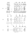
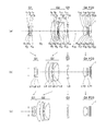
- FIG. 3 is a cross-sectional view along the optical axis showing the optical configuration of the zoom lens according to Example 1 when the first object is in focus, where (a) is a wide-angle end, (b) is an intermediate end, and (c) is a cross-section at a telephoto end.
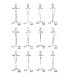
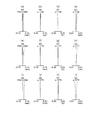
- FIG. 6 is a diagram illustrating spherical aberration (SA), astigmatism (AS), distortion (DT), and lateral chromatic aberration (CC) when the first object is in focus in the zoom lens according to Example 1; (d) is an aberration diagram at the wide-angle end, (e) to (h) are intermediate, and (i) to (l) are aberration diagrams at the telephoto end.
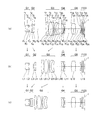
- FIG. 6 is a cross-sectional view along an optical axis showing an optical configuration of the zoom lens according to Example 2 when the first object is focused, where (a) is a wide-angle end, (b) is an intermediate end, and (c) is a cross-section at a telephoto end.
- SA spherical aberration
- AS astigmatism
- DT distortion
- CC lateral chromatic aberration
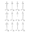
- FIG. 10 is a diagram illustrating spherical aberration (SA), astigmatism (AS), distortion (DT), and lateral chromatic aberration (CC) when the first object is in focus in the zoom lens according to Example 2; (d) is an aberration diagram at the wide-angle end, (e) to (h) are intermediate, and (i) to (l) are aberration diagrams at the telephoto end.
- FIG. 6 is a cross-sectional view taken along the optical axis showing the optical configuration of the zoom lens according to Example 3 when the first object is focused, in which (a) is a wide-angle end, (b) is an intermediate end, and (c) is a cross-section at a telephoto end.
- FIG. 10 is a diagram illustrating spherical aberration (SA), astigmatism (AS), distortion (DT), and lateral chromatic aberration (CC) when the first object is in focus in the zoom lens according to Example 3; (d) is an aberration diagram at the wide-angle end, (e) to (h) are intermediate, and (i) to (l) are aberration diagrams at the telephoto end.
- FIG. 6 is a cross-sectional view along an optical axis showing an optical configuration of a zoom lens according to Example 4 when focusing on a first object, where (a) is a wide-angle end, (b) is an intermediate end, and (c) is a cross-section at a telephoto end.
- FIG. 7A is a diagram illustrating spherical aberration (SA), astigmatism (AS), distortion (DT), and lateral chromatic aberration (CC) when the first object is in focus in the zoom lens according to Example 4; (d) is an aberration diagram at the wide-angle end, (e) to (h) are intermediate, and (i) to (l) are aberration diagrams at the telephoto end.
- FIG. 10 is a cross-sectional view along an optical axis showing an optical configuration of the zoom lens according to Example 5 when the first object is in focus, where (a) is a wide-angle end, (b) is a middle, and (c) is a cross-section at a telephoto end.
- FIG. 10 is a diagram illustrating spherical aberration (SA), astigmatism (AS), distortion (DT), and lateral chromatic aberration (CC) when the first object is in focus in the zoom lens according to Example 5; (d) is an aberration diagram at the wide-angle end, (e) to (h) are intermediate, and (i) to (l) are aberration diagrams at the telephoto end.
- FIG. 10 is a cross-sectional view along the optical axis showing an optical configuration of the zoom lens according to Example 6 when the first object is focused, where (a) is a wide-angle end, (b) is a middle, and (c) is a cross-section at a telephoto end.
- FIG. 10 is a diagram illustrating spherical aberration (SA), astigmatism (AS), distortion (DT), and lateral chromatic aberration (CC) when the first object is in focus in the zoom lens according to Example 6; (d) is an aberration diagram at the wide-angle end, (e) to (h) are intermediate, and (i) to (l) are aberration diagrams at the telephoto end.
- FIG. 10 is a cross-sectional view along an optical axis showing an optical configuration of the zoom lens according to Example 7 when the first object is focused, where (a) is a wide-angle end, (b) is an intermediate end, and (c) is a cross-section at a telephoto end.
- FIGS. 9A and 9B are cross-sectional views along an optical axis showing an optical configuration of the zoom lens according to Example 8 when the first object is focused, where FIG. 9A is a wide-angle end, FIG. 9B is a middle, and FIG. FIG. FIG.
- FIG. 9A is a diagram illustrating spherical aberration (SA), astigmatism (AS), distortion (DT), and lateral chromatic aberration (CC) when the first object is focused on a zoom lens according to Example 8; (d) is an aberration diagram at the wide-angle end, (e) to (h) are intermediate, and (i) to (l) are aberration diagrams at the telephoto end.
- FIG. 10 is a cross-sectional view taken along an optical axis showing an optical configuration of the zoom lens according to Example 9 when the first object is in focus, where (a) is a wide-angle end, (b) is an intermediate end, and (c) is a cross-section at a telephoto end.
- FIG. 10A is a diagram illustrating spherical aberration (SA), astigmatism (AS), distortion (DT), and lateral chromatic aberration (CC) when the first object is focused on a zoom lens according to Example 9; (d) is an aberration diagram at the wide-angle end, (e) to (h) are intermediate, and (i) to (l) are aberration diagrams at the telephoto end.
- FIG. 14 is a cross-sectional view taken along the optical axis showing the optical configuration of the zoom lens according to Example 10 when the first object is in focus, where (a) is a wide-angle end, (b) is an intermediate end, and (c) is a cross-section at a telephoto end.
- FIG. 14 is a diagram illustrating spherical aberration (SA), astigmatism (AS), distortion (DT), and lateral chromatic aberration (CC) when the first object is in focus in the zoom lens according to Example 10; (d) is an aberration diagram at the wide-angle end, (e) to (h) are intermediate, and (i) to (l) are aberration diagrams at the telephoto end.
- FIG. 14 is a cross-sectional view taken along the optical axis showing the optical configuration of the zoom lens according to Example 11 when the first object is in focus, where (a) is a wide-angle end, (b) is an intermediate end, and (c) is a cross-section at a telephoto end.
- FIG. 14 is a diagram illustrating spherical aberration (SA), astigmatism (AS), distortion (DT), and lateral chromatic aberration (CC) when the first object is in focus in the zoom lens according to Example 11; (d) is an aberration diagram at the wide-angle end, (e) to (h) are intermediate, and (i) to (l) are aberration diagrams at the telephoto end.
- FIG. 14 is a cross-sectional view taken along the optical axis showing the optical configuration of the zoom lens according to Example 12 when the first object is in focus, where (a) is a wide-angle end, (b) is an intermediate end, and (c) is a cross-section at a telephoto end.
- SA spherical aberration
- AS astigmatism
- DT distortion
- CC lateral chromatic aberration
- FIG. 14 is a diagram showing spherical aberration (SA), astigmatism (AS), distortion (DT), and lateral chromatic aberration (CC) when the first object is in focus in the zoom lens according to Example 12; (d) is an aberration diagram at the wide-angle end, (e) to (h) are intermediate, and (i) to (l) are aberration diagrams at the telephoto end.
- FIG. 14 is a cross-sectional view taken along an optical axis showing an optical configuration of the zoom lens according to Example 13 when the first object is focused, in which (a) is a wide-angle end, (b) is a middle, and (c) is a cross-section at a telephoto end.
- FIG. 14 is a diagram illustrating spherical aberration (SA), astigmatism (AS), distortion (DT), and lateral chromatic aberration (CC) when the first object is in focus in the zoom lens according to Example 13; (d) is an aberration diagram at the wide-angle end, (e) to (h) are intermediate, and (i) to (l) are aberration diagrams at the telephoto end.
- FIG. 17 is a cross-sectional view taken along the optical axis showing the optical configuration of the zoom lens according to Example 14 when the first object is in focus, where (a) is a wide-angle end, (b) is a middle, and (c) is a cross-section at a telephoto end.
- SA spherical aberration
- AS astigmatism
- DT distortion
- CC lateral chromatic aberration
- the zoom imaging apparatus includes a mount unit, a zoom lens that forms an image of light incident from the mount unit, and an image sensor that is disposed at an image formation position.
- the zoom lens includes a plurality of lens groups. And a focus lens group, and satisfy the following conditional expressions (1) and (2).
- the mount side is the object side
- the image sensor side is the image side
- f Lt and f Lw are the focal lengths of the zoom lens when focused on the first object
- f Lt is the focal length at the telephoto end
- f Lw is the focal length at the wide angle end
- y W7d and y w7d ' is first given ray a ray height of the first predetermined light beam at a position intersecting the image plane
- y w7d ' is the beam height in the defocused state
- the defocused state is a state in which the focus lens group is moved by ⁇ s1 in a state in which the first object is focused
- ⁇ s1 f Lw ⁇ 0.005
- Securing the zoom ratio so as not to fall below the lower limit of conditional expression (1) makes it possible to obtain an image of a desired size without replacing the adapter as in the prior art.
- the optical device is an endoscope
- an image having a size desired by the person performing the operation can be displayed on the television monitor.
- Conditional expression (2) is a conditional expression regarding the change amount ⁇ y (change amount of the image height).
- Y w7d and y w7d ′ in the conditional expression (2) will be described with reference to FIG. 2A is a view showing the entire zoom lens, and FIG. 2B is an enlarged view showing the vicinity of the image plane.
- Lw7 represents the first predetermined light beam
- LA represents the most object side lens of the zoom lens
- Fo represents the focus lens group.
- FIG. 2 is a diagram showing a state in which the image height changes due to the movement of the focus lens group Fo.
- P1 is the position of the focus lens group Fo when the first object is focused.
- P2 is a position where the focus lens group Fo is moved by a minute amount ⁇ S.
- the movement of the focus lens group Fo is exaggerated in FIG.
- the first predetermined light beam L w7 is a light beam having an angle of view of 7 degrees at the wide angle end.
- the first predetermined light beam L w7 passes through the center of the lens surface on the object side of the lens LA.
- the focus lens group Fo In a state where the position of the focus lens group Fo coincides with P1, the light beam incident on the focus lens group Fo travels as indicated by the solid line and reaches the image position.
- the image height at this time is y w7d . From this state, the focus lens group Fo is caused to perform a wobbling operation. As a result, the focus lens group Fo moves to the position P2.
- the light beam incident on the focus lens group Fo travels as indicated by a broken line and reaches the image position.
- the image height at this time is y w7d ′ .
- the image height varies between y w7d and y w7d ′ according to the position of the focus lens group Fo.
- the focus lens group Fo In autofocus, the focus lens group Fo is made to perform a wobbling operation, and the focus is always maintained. Therefore, in autofocus, it is required that the amount of change ⁇ y is small when the focus lens group Fo is moved. By satisfying conditional expression (2), it is possible to suppress an increase in the amount of change ⁇ y at the wide-angle end.
- the size of the image can be freely changed, and when the autofocus is performed on the image of a desired size, the change is achieved. It is possible to perform autofocus while suppressing an increase in the amount ⁇ y.
- conditional expression (2) instead of conditional expression (2), the following conditional expression (2 ′) should be satisfied.
- conditional expression (2 ′′) instead of conditional expression (2).
- y t5d ′ are the heights of the second predetermined light rays at the position where the second predetermined light rays intersect the image plane
- y t5d is the light ray height when focused on the first object
- y t5d ' is the beam height in the defocused state
- the second predetermined light beam is a light beam having a field angle of 5 degrees at the telephoto end, and passes through the center of the lens surface closest to the object side of the zoom lens, It is.
- conditional expression (3) instead of conditional expression (3), the following conditional expression (3 ′) should be satisfied.
- conditional expression (3 ′′) instead of conditional expression (3).
- the plurality of lens groups have a movable lens group, and the focus lens group is located on the image side with respect to the movable lens group.
- the imaging magnification can be changed by the movable lens group.
- the change amount of the image position and the change amount of the image height due to the movement of the focus lens group greatly change according to the movement state of the movable lens group.
- the change in the image position and the change in the image height due to the movement of the focus lens group are greatly influenced by the movement of the movable lens group.
- the focus lens group is positioned closer to the image side than the movable lens group. By doing so, the influence of the movement of the movable lens group can be almost ignored. As a result, an increase in the change amount ⁇ y can be suppressed in the range from the wide-angle end to the telephoto end.
- Focus sensitivity does not change significantly in the range from the wide-angle end to the telephoto end. Since the change in focus sensitivity is small, it is easy to control the movement of the focus lens group. Focus sensitivity is an amount indicating the amount of movement of the image plane relative to the amount of movement of the focus lens group.
- the height of the axial ray is low.
- the focus lens group closer to the image side than the movable lens group, the height of the on-axis light beam passing through the focus lens group is lowered. Therefore, it becomes easy to suppress the occurrence of spherical aberration.
- ⁇ ctw (1- ⁇ fcw ⁇ ⁇ fcw ) ⁇ ⁇ w ' ⁇ ⁇ w ', ⁇ fcw and ⁇ w ′ are lateral magnifications at the wide-angle end when the first object is focused, ⁇ fcw is the lateral magnification of the focus lens group, and ⁇ w ′ is closer to the image side than the focus lens group.
- the first object is an object when the object distance is 1000 mm
- the object point distance is the distance from the lens surface closest to the object of the zoom lens to the object It is.
- Conditional expression (4) relates to the focus sensitivity at the wide-angle end.
- the focus sensitivity is an amount indicating the amount of movement of the image plane with respect to the amount of movement of the focus lens group.
- conditional expression (4) By exceeding the lower limit value of conditional expression (4), it is possible to suppress an increase in the amount of movement of the focus lens group during focusing. As a result, fluctuations in astigmatism during focusing can be suppressed. In addition, since an increase in the amount of movement of the focus lens group can be suppressed, the movement space of the focus lens group can be reduced. As a result, the zoom lens can be miniaturized and the zoom imaging apparatus can be miniaturized.
- conditional expression (4 ′) should be satisfied. 0.555 ⁇
- conditional expression (4 ′′) is satisfied instead of conditional expression (4). 0.555 ⁇
- f fc is the focal length of the focus lens group
- f Lw is a focal length at the wide-angle end of the zoom lens when focused on the first object
- the first object is an object when the object distance is 1000 mm
- the object point distance is the distance from the lens surface closest to the object of the zoom lens to the object It is.
- Conditional expression (5) is a ratio of two focal lengths. One is the focal length of the focus lens group, and the other is the focal length of the zoom lens. The focal length of this zoom lens is the focal length at the wide-angle end when the first object is focused.
- conditional expression (5) By exceeding the lower limit value of conditional expression (5), the Petzval sum can be set well in the focus lens group, and astigmatism can be corrected well. Thereby, good optical performance can be maintained.
- conditional expression (5) instead of conditional expression (5), the following conditional expression (5 ′) should be satisfied. -4 ⁇ f fc / f Lw ⁇ -0.5 (5 ') Furthermore, it is more preferable to satisfy the following conditional expression (5 ′′) instead of conditional expression (5). ⁇ 2.4 ⁇ f fc / f Lw ⁇ 0.8 (5 ′′)
- d pg and d fc are thicknesses on the optical axis of the lens group
- d pg is the thickness of the lens unit having the largest positive refractive power among the thicknesses of the lens unit located on the object side of the focus lens unit
- d fc is the thickness of the focus lens group
- Conditional expression (6) is the ratio of the thickness of the two lens groups on the optical axis.
- One is the thickness of the predetermined positive lens group, and the other is the thickness of the focus lens group.
- the predetermined positive lens group is a lens group having the largest positive refractive power among the lens groups located on the object side of the focus lens group.
- the thickness is the thickness on the optical axis.
- the axial ray height is higher on the object side than the focus lens group.
- a lens group having the largest positive refractive power is arranged to correct the aberration.
- conditional expression (6) the thickness of the lens unit having the largest positive refractive power does not become too thick. Therefore, falling below the upper limit value of conditional expression (6) is effective in shortening the overall length of the optical system.
- conditional expression (6) instead of conditional expression (6), the following conditional expression (6 ′) should be satisfied. 2.7 ⁇ d pg / d fc ⁇ 22 (6 ′) Furthermore, it is more preferable that the following conditional expression (6 ′′) is satisfied instead of conditional expression (6). 3.9 ⁇ d pg / d fc ⁇ 20 (6 ′′)
- the lens group having negative refractive power that satisfies the following conditional expression (7) is located closer to the object side than the lens group having positive refractive power.
- d ng and d pg are the thicknesses on the optical axis of the lens group
- d ng is the thickness of the lens unit having the largest negative refractive power among the thicknesses of the lens unit located on the object side of the focus lens unit
- d pg is the thickness of the lens unit having the largest positive refractive power among the thicknesses of the lens unit located on the object side of the focus lens unit
- Conditional expression (7) relates to the ratio of the thickness on the optical axis of the two lens groups.
- One is the thickness of a predetermined positive lens group, and the other is the thickness of a predetermined negative lens group.
- the predetermined positive lens group is a lens group having the largest positive refractive power among the lens groups located on the object side of the focus lens group.
- the predetermined negative lens group is a lens group having the largest negative refracting power among the lens groups located closer to the object side than the focus lens group.
- Conditional expression (7) is a conditional expression for satisfactorily correcting spherical aberration while suppressing an increase in the total length of the optical system.
- the total length of the optical system can be shortened by exceeding the lower limit value of conditional expression (7).
- conditional expression (7) By falling below the upper limit value of conditional expression (7), it is possible to satisfactorily correct spherical aberration.
- conditional expression (7) instead of conditional expression (7), the following conditional expression (7 ′) should be satisfied. 0.15 ⁇ d ng / d pg ⁇ 0.5 (7 ′) Furthermore, it is better to satisfy the following conditional expression (7 ′′) instead of conditional expression (7). 0.17 ⁇ d ng / d pg ⁇ 0.35 (7 ′′)
- ⁇ fc and ⁇ L1 are effective diameters at the wide-angle end when focusing on the first object
- ⁇ fc is the effective diameter of the lens surface located closest to the object side of the focus lens group
- ⁇ L1 is the effective diameter of the lens surface located closest to the object side of the zoom lens
- the first object is an object when the object distance is 1000 mm
- the object point distance is the distance from the lens surface closest to the object of the zoom lens to the object
- the effective diameter is the maximum diameter of the target lens surface in the range through which light rays contributing to image formation pass, It is.
- Conditional expression (8) relates to the ratio of the two effective diameters.
- One is the effective diameter of the lens surface located closest to the object side of the focus lens group, and the other is the effective diameter of the lens surface located closest to the object side of the zoom lens.
- the effective diameter of the zoom lens is preferably such that the optical path of the exit pupil is guided to the image sensor with little or no vignetting, and at the same time miniaturization is achieved.
- conditional expression (8) By exceeding the lower limit value of conditional expression (8), it is possible to prevent the lens group closest to the object side from becoming large. Thus, exceeding the lower limit value of conditional expression (8) is advantageous for downsizing of the optical system. As a result, it is possible to satisfactorily correct spherical aberration while achieving downsizing of the optical system.
- conditional expression (8) By falling below the upper limit value of conditional expression (8), it is possible to correct spherical aberration and coma aberration in the focus lens group while preventing an increase in size of the focus lens group.
- conditional expression (8) it is preferable to satisfy the following conditional expression (8 ′). 1 ⁇ fc / ⁇ L1 ⁇ 2.5 (8 ′) Further, it is more preferable that the following conditional expression (8 ′′) is satisfied instead of conditional expression (8). 1.1 ⁇ fc / ⁇ L1 ⁇ 2 (8 ′′)
- f ng is the focal length of the lens unit having the largest negative refractive power among the focal lengths of the lens unit located on the object side of the focus lens unit
- f pg is the focal length of the lens unit having the largest positive refractive power among the focal lengths of the lens unit located on the object side of the focus lens unit
- Conditional expression (9) relates to the ratio of the focal lengths of the two lens groups.
- One is the focal length of the predetermined negative lens group, and the other is the focal length of the predetermined positive lens group.
- the predetermined negative lens group is a lens group having the largest negative refracting power among the lens groups located closer to the object side than the focus lens group.
- the predetermined positive lens group is a lens group having the largest positive refractive power among the lens groups located on the object side of the focus lens group.
- conditional expression (9) the refractive power of the predetermined negative lens group and the refractive power of the predetermined positive lens group can be balanced.
- the Petzval sum can be set satisfactorily, astigmatism can be corrected satisfactorily. Thereby, good optical performance can be maintained.
- conditional expression (9 ′) should be satisfied. ⁇ 5 ⁇ f ng / f pg ⁇ 0.9 (9 ′) Furthermore, it is more preferable that the following conditional expression (9 ′′) is satisfied instead of conditional expression (9). -3 ⁇ f ng / f pg ⁇ -1.1 (9 '')
- f ng is the focal length of the lens unit having the largest negative refractive power among the focal lengths of the lens unit located on the object side of the focus lens unit
- f Lt is the focal length at the telephoto end of the zoom lens when focused on the first object
- the first object is an object when the object distance is 1000 mm
- the object point distance is the distance from the lens surface closest to the object of the zoom lens to the object It is.
- Conditional expression (10) relates to the ratio of the focal lengths of the two lens groups.
- One is the focal length of the lens group having the largest negative refractive power among the focal lengths of the lens group located on the object side of the focus lens group, and the other is at the telephoto end of the zoom lens when focused on the first object.
- the focal length is the focal length of the lens group having the largest negative refractive power among the focal lengths of the lens group located on the object side of the focus lens group, and the other is at the telephoto end of the zoom lens when focused on the first object.
- conditional expression (10 ′) should be satisfied. ⁇ 3 ⁇ f ng / f Lt ⁇ 0.25 (10 ′) Furthermore, it is more preferable that the following conditional expression (10 ′′) is satisfied instead of conditional expression (10). ⁇ 1.7 ⁇ f ng / f Lt ⁇ 0.3 (10 ′′)
- ⁇ ctt (1- ⁇ fct ⁇ ⁇ fct ) ⁇ ⁇ t ' ⁇ ⁇ t '
- ⁇ ctw (1- ⁇ fcw ⁇ ⁇ fcw ) ⁇ ⁇ w ' ⁇ ⁇ w '
- ⁇ fct and ⁇ t ′ are lateral magnifications at the telephoto end when the first object is focused
- ⁇ fct is the lateral magnification of the focus lens group
- ⁇ t ′ is the image side from the focus lens group.
- Lateral magnification of the lens group located at ⁇ fcw and ⁇ w ′ are lateral magnifications at the wide-angle end when the first object is focused, ⁇ fcw is the lateral magnification of the focus lens group, and ⁇ w ′ is the image side from the focus lens group.
- Lateral magnification of the lens group located at The first object is an object when the object distance is 1000 mm, The object point distance is the distance from the lens surface closest to the object of the zoom lens to the object It is.
- Conditional expression (11) relates to the ratio between the focus sensitivity at the telephoto end and the focus sensitivity at the wide-angle end.
- the focus sensitivity is an amount indicating the amount of movement of the image plane with respect to the amount of movement of the focus lens group.
- conditional expression (11 ′) instead of conditional expression (11 ), the following conditional expression (11 ′) should be satisfied. 0.9 ⁇
- ⁇ L1 is the effective diameter of the lens surface located closest to the object side of the zoom lens, and is the effective diameter at the wide-angle end when focused on the first object
- f lt is the focal length at the telephoto end of the zoom lens when focused on the first object
- the first object is an object when the object distance is 1000 mm
- the object point distance is the distance from the lens surface closest to the object of the zoom lens to the object
- the effective diameter is the maximum diameter of the target lens surface in the range through which light rays contributing to image formation pass, It is.
- Conditional expression (12) is a ratio of the effective diameter of the lens surface located closest to the object side of the zoom lens and the focal length of the zoom lens at the telephoto end when the first object is focused.
- the effective diameter of the lens is the maximum diameter in the range through which light rays contributing to image formation at the wide-angle end when focused on the first object, that is, the diameter defined by the peripheral light rays.
- the effective diameter of the lens surface located closest to the object side of the zoom lens can be reduced, so that the optical system can be reduced in size.
- conditional expression (12 ′) should be satisfied. 0.04 ⁇ L1 / f lt ⁇ 0.18 (12 ′) Furthermore, it is more preferable that the following conditional expression (12 ′′) is satisfied instead of conditional expression (12). 0.05 ⁇ L1 / f lt ⁇ 0.15 (12 ′′)
- the focus lens group has negative refractive power
- the plurality of lens groups have at least one lens group having negative refractive power
- a lens group having negative refractive power can be used for zooming.
- the zoom ratio can be easily increased.
- the final lens group is disposed closest to the image side, and the final lens group includes a positive lens disposed closest to the object side and a negative lens disposed closest to the image side. It is preferable to have.
- the final lens group is a lens group arranged closest to the image side in the zoom lens.
- the final lens group by arranging the lenses in order of the positive lens and the negative lens from the object side, the light rays converged by the positive lens can be diverged by the negative lens.
- the angle with respect to the optical axis of the light beam passing through the final lens group can be made gentle. Therefore, the occurrence of off-axis aberrations can be particularly suppressed.
- the focus lens group is preferably a wobbling lens group that performs a wobbling operation along the optical axis with a movement amount smaller than a movement amount at the time of focusing.
- the contrast AF method a wobbling operation is performed to maintain a focused state.
- the change in contrast is always measured.
- the focus lens group is appropriately moved to operate again to focus again.
- the entire length of the zoom lens is fixed.
- the entire zoom imaging device becomes large. Therefore, by fixing the entire length of the zoom lens, it is possible to prevent the zoom imaging apparatus from being enlarged and to be manufactured easily.
- r fcff is the radius of curvature of the object side lens surface of the lens located closest to the object side in the focus lens group
- r fcfb is the radius of curvature of the image side lens surface of the lens located closest to the image side in the focus lens group
- Conditional expression (13) relates to the shape of the focus lens group.
- the shape of the focus lens group becomes a shape suitable for correcting spherical aberration. Therefore, it is possible to suppress the fluctuation of spherical aberration during focusing.
- conditional expression (13 ′) instead of conditional expression (13).
- conditional expression (13 ) ⁇ 4 ⁇ (r fcff + r fcfb ) / (r fcff ⁇ r fcfb ) ⁇ 4 (13 ′)
- conditional expression (13 ′′) is satisfied instead of conditional expression (13). ⁇ 3 ⁇ (r fcff + r fcfb ) / (r fcff ⁇ r fcfb ) ⁇ 2 (13 ′′)
- r lf is the radius of curvature of the object side lens surface of the lens located closest to the image side
- r lb is the radius of curvature of the image side lens surface of the lens located closest to the image side
- Conditional expression (14) relates to the shape of the lens located closest to the image side.
- Astigmatism can be satisfactorily corrected by exceeding the lower limit of conditional expression (14). As a result, good optical performance can be maintained. By falling below the upper limit value of conditional expression (14), spherical aberration can be corrected well. As a result, good optical performance can be maintained.
- conditional expression (14 ′) instead of conditional expression (14).
- conditional expression (14 ′) instead of conditional expression (14).
- conditional expression (14 ′) instead of conditional expression (14).
- conditional expression (14 ′′) instead of conditional expression (14).
- the zoom imaging apparatus of the present embodiment includes a mount unit, a zoom lens that forms an image of light incident from the mount unit, and an image sensor that is disposed at the imaging position.
- the fourth lens group is a focus lens group, and only the second lens group and the fourth lens group are used for zooming from the wide-angle end to the telephoto end.
- the first lens group, the third lens group, and the fifth lens group move and are fixed.
- the zoom lens includes, in order from the object side, a first lens group having a positive refractive power, a second lens group having a negative refractive power, and a third lens having a positive refractive power. It includes a lens group, a fourth lens group having negative refractive power, and a fifth lens group having positive refractive power (hereinafter referred to as “first configuration”).
- the zoom imaging apparatus of the present embodiment includes a mount unit, a zoom lens that forms an image of light incident from the mount unit, and an image sensor that is disposed at the imaging position.
- the fourth lens group is a focus lens group, and only the second lens group and the third lens group move during zooming from the wide-angle end to the telephoto end, and the first lens The group, the fourth lens group, and the fifth lens group are fixed.
- the zoom lens includes, in order from the object side, a first lens group, a second lens group having a negative refractive power, a third lens group having a positive refractive power, and a negative lens group.
- the lens unit includes a fourth lens group having a refractive power and a fifth lens group having a positive refractive power (hereinafter referred to as “second configuration”).
- the zoom imaging apparatus of the present embodiment includes a mount unit, a zoom lens that forms an image of light incident from the mount unit, and an image sensor that is disposed at the imaging position.
- the third lens group is a focus lens group, and only the first lens group and the second lens group move during zooming from the wide-angle end to the telephoto end, and the third lens group and the fourth lens group It is fixed.
- the zoom lens includes, in order from the object side, a first lens group having a negative refractive power, a second lens group having a positive refractive power, and a third lens having a negative refractive power.
- the lens unit includes a lens unit and a fourth lens unit having a positive refractive power (hereinafter referred to as “third configuration”).
- the zoom lens having the first configuration, the zoom lens having the second configuration, and the zoom lens having the third configuration can all be used as an imaging optical system for an endoscope.
- the endoscope imaging optical system When the endoscope imaging optical system is combined with the endoscope optical system, the entrance pupil position is restricted.
- an imaging optical system for an endoscope does not have an aperture stop. Therefore, the aperture of the imaging light beam is determined by the exit pupil diameter of the endoscope optical system.
- the eye point of the endoscope optical system is generally a position where there is no problem in visual observation, for example, a position several mm from the end face of the eyepiece.
- the focus lens group is the fourth lens group in the first configuration and the second configuration, and the focus lens group is the third lens group in the third configuration.
- the position of the focus lens group can be moved away from the entrance pupil position, so that the angle of the light beam incident on the focus lens group with respect to the optical axis can be reduced.
- an increase in the change amount ⁇ y can be suppressed when the focus lens group is moved.
- the refractive power of the focus lens group is negative, the focus sensitivity can be increased. As a result, an increase in the amount of movement of the focus lens group during focusing can be suppressed.
- a fifth lens group having positive refractive power is disposed on the image side of the focus lens group (fourth lens group).
- the focus lens group A fourth lens group having a positive refractive power is disposed on the image side of the third lens group.
- a lens group having a positive refractive power is arranged after a lens group having a negative refractive power (focus lens group). Therefore, it is possible to suppress a change in the angle of view during focusing.
- the movement of the lens group in each configuration is as follows.
- the first configuration only the second lens group and the fourth lens group move, and the first lens group, the third lens group, and the fifth lens group are fixed.
- the second configuration only the second lens group and the third lens group move, and the first lens group, the fourth lens group, and the fifth lens group are fixed.
- the third configuration only the first lens group and the second lens group move, and the third lens group and the fourth lens group are fixed.
- the second lens group and the third lens group become main variators.
- the first lens group and the second lens group become main variators.
- the change amount of the image position and the change amount of the image height due to the movement of the focus lens group greatly change according to the movement state of the main variator.
- the change in the image position and the change in the image height due to the movement of the focus lens group are greatly influenced by the movement state of the main variator.
- the focus lens group is the fourth lens group.
- the focus lens group is the third lens group.
- the focus lens group is arranged after the main variator. Therefore, the influence of the main variator can be ignored, so that the focus sensitivity does not change greatly. Since the change in focus sensitivity is small, it is easy to control the movement of the focus lens group.
- the lens diameter can be reduced by the second lens group and the fourth lens group. Therefore, the optical system can be made compact by moving the second lens group and the fourth lens group. Further, by using two lens groups that move during zooming, it is possible to relatively easily control the movement of the lens groups and the mechanical configuration.
- the zoom imaging apparatus of the present embodiment includes a mount unit, a zoom lens that forms an image of light incident from the mount unit, and an image sensor that is disposed at the imaging position. It has a lens group and a focus lens group, and satisfies the following conditional expressions (1) and (15).
- the mount side is the object side
- the image sensor side is the image side
- f Lt and f Lw are the focal lengths of the zoom lens when focused on the first object
- f Lt is the focal length at the telephoto end
- f Lw is the focal length at the wide angle end
- y W7d and y w7d ' is first given ray a ray height of the first predetermined light beam at a position intersecting the image plane
- y w7d ' is the beam height in the defocused state
- conditional expression (1) Since the technical significance of conditional expression (1) has already been explained, explanation here is omitted.
- Conditional expression (15) represents how much the change in the image height is conspicuous on the image sensor when the focus lens group fluctuates slightly. Since the amount of change in image height is divided by the pixel pitch, the smaller the pixel pitch, the more noticeable the change in image height. Further, conditional expression (15) reflects that the image pitch changes more conspicuously as the number of pixels of the image sensor increases because the pixel pitch becomes finer as the total number of pixels increases for the same sensor size.
- conditional expressions (1) and (15) By satisfying conditional expressions (1) and (15), the size of the image can be freely changed, and the amount of change ⁇ y increases when autofocus is performed on an image of a desired size. It is possible to perform auto-focusing with suppressed.
- conditional expression (15 ′) should be satisfied.
- conditional expression (15 ′′) is satisfied instead of conditional expression (15).
- the positive and negative refractive powers are based on the paraxial radius of curvature.
- the zoom lenses of the following embodiments are connected to the eyepieces of optical devices when in use.
- an aperture stop is disposed in the optical system on the optical apparatus side, no aperture stop is provided on the zoom lens side.
- an aperture stop is required.
- the virtual diaphragm in the following description of the embodiments is an aperture diaphragm provided for design. Therefore, in an actual zoom lens, the aperture stop does not physically exist.
- an aperture for example, a flare aperture
- shielding unnecessary light may be arranged at the position of the virtual aperture.
- the position of the first object is a position when the object point distance is 1000 mm.
- the position of the second object is a position when the object point distance is 333.33 mm. At the position of the second object, the object is closest to the zoom lens.
- FIG. 3 is a cross-sectional view (lens cross-sectional view) along the optical axis showing the optical configuration of the zoom lens of Example 1 when focusing on the first object, in which (a) is a cross-sectional view at the wide-angle end; ) Is a cross-sectional view in the intermediate focal length state, and (c) is a cross-sectional view at the telephoto end.
- F represents a filter
- CG represents a cover glass
- I represents an imaging surface (image surface) of the imaging device.
- CG represents a color separation prism instead of a cover glass.
- FIG. 4 is an aberration diagram of the zoom lens according to Example 1 when the first object is in focus.
- ⁇ is a half angle of view.
- the symbols in the aberration diagrams are the same in the examples described later.
- SA spherical aberration
- AS astigmatism
- DT distortion
- CC chromatomatic aberration
- SA spherical aberration
- AS astigmatism
- DT distortion
- CC lateral chromatic aberration
- (i), (j), (k), and (l) respectively indicate spherical aberration (SA), astigmatism (AS), distortion (DT), and lateral chromatic aberration (CC) at the telephoto end. ing.
- SA spherical aberration
- AS astigmatism
- DT distortion
- CC lateral chromatic aberration
- the zoom lens of Example 1 includes, in order from the object side, a first lens group G1 having a positive refractive power, a second lens group G2 having a negative refractive power, and a positive refractive power.
- the first lens group G1 includes a negative meniscus lens L1 having a convex surface facing the image side, a biconvex lens L2, and a negative meniscus lens L3 having a convex surface facing the image side.
- the biconvex lens L2 and the negative meniscus lens L3 are cemented.
- the virtual aperture is set on the image side surface of the negative meniscus lens L3.
- the second lens group G2 includes a positive meniscus lens L4 having a convex surface directed toward the image side, and a biconcave negative lens L5.
- the positive meniscus lens L4 and the biconcave negative lens L5 are cemented.
- the third lens group G3 includes a biconvex positive lens L6, a biconvex positive lens L7, and a biconcave negative lens L8.
- the biconvex positive lens L7 and the biconcave negative lens L8 are cemented.
- the fourth lens group G4 is composed of a biconcave negative lens L9.
- the fifth lens group G5 includes a biconvex positive lens L10 and a negative meniscus lens L11 having a convex surface directed toward the image side.
- the biconvex positive lens L10 and the negative meniscus lens L11 are cemented.
- the first lens group G1 is fixed, the second lens group G2 is moved to the image side, the third lens group G3 is fixed, and the fourth lens group G4 is an image.
- the fifth lens group G5 is fixed.
- focusing on the subject is performed by moving the fourth lens group G4.
- the biconcave negative lens L9 moves to the image side.
- FIG. 5 is a cross-sectional view along the optical axis showing the optical configuration of the zoom lens of Example 2 when the first object is in focus.
- FIG. 6 is an aberration diagram of the zoom lens of Example 2 when the first object is in focus.
- the zoom lens of Example 2 includes, in order from the object side, a first lens group G1 having a positive refractive power, a second lens group G2 having a negative refractive power, and a positive refractive power.
- the first lens group G1 includes a negative meniscus lens L1 having a convex surface directed toward the image side, a biconvex lens L2, and a biconcave negative lens L3.
- the biconvex lens L2 and the biconcave negative lens L3 are cemented.
- the virtual diaphragm is set on the image side surface of the biconcave negative lens L3.
- the second lens group G2 includes a biconcave negative lens L4 and a positive meniscus lens L5 having a convex surface directed toward the object side.
- the biconcave negative lens L4 and the positive meniscus lens L5 are cemented.
- the third lens group G3 includes a positive meniscus lens L6 having a convex surface facing the image side, a biconvex positive lens L7, a negative meniscus lens L8 having a convex surface facing the image side, and a negative meniscus lens having a convex surface facing the object side.
- L9 and a positive meniscus lens L10 having a convex surface facing the object side.
- the biconvex positive lens L7 and the negative meniscus lens L8 are cemented.
- the negative meniscus lens L9 and the positive meniscus lens L10 are cemented.
- the fourth lens group G4 includes a negative meniscus lens L11 having a convex surface directed toward the image side, and a biconcave negative lens L12.
- the negative meniscus lens L11 and the biconcave negative lens L12 are cemented.
- the fifth lens group G5 includes a biconvex positive lens L13 and a biconcave negative lens L14.
- the first lens group G1 is fixed, the second lens group G2 is moved to the image side, the third lens group G3 is fixed, and the fourth lens group G4 is an image.
- the fifth lens group G5 is fixed.
- focusing on the subject is performed by moving the fourth lens group G4.
- the negative meniscus lens L11 and the biconcave negative lens L12 move to the image side.
- FIG. 7 is a cross-sectional view along the optical axis showing the optical configuration of the zoom lens of Example 3 when the first object is in focus.
- FIG. 8 is an aberration diagram of the zoom lens of Example 3 when the first object is in focus.
- the zoom lens according to the third exemplary embodiment includes, in order from the object side, a first lens group G1 having a positive refractive power, a second lens group G2 having a negative refractive power, and a positive refractive power.
- the first lens group G1 includes a negative meniscus lens L1 having a convex surface directed toward the object side, a biconvex lens L2, and a biconcave negative lens L3.
- the biconvex lens L2 and the biconcave negative lens L3 are cemented.
- the virtual diaphragm is set on the image side surface of the biconcave negative lens L3.
- the second lens group G2 includes a biconcave negative lens L4 and a positive meniscus lens L5 having a convex surface directed toward the object side.
- the biconcave negative lens L4 and the positive meniscus lens L5 are cemented.
- the third lens group G3 includes a biconvex positive lens L6, a biconvex positive lens L7, a biconcave negative lens L8, a negative meniscus lens L9 having a convex surface facing the object side, and a biconvex positive lens L10. .
- the biconvex positive lens L7 and the biconcave negative lens L8 are cemented.
- the negative meniscus lens L9 and the biconvex positive lens L10 are cemented.
- the fourth lens group G4 is composed of a biconcave negative lens L11.
- the fifth lens group G5 includes a biconvex positive lens L12, a biconvex positive lens L13, a negative meniscus lens L14 with a convex surface facing the image side, a positive meniscus lens L15 with a convex surface facing the image side, and a biconcave negative lens. L16.
- the biconvex positive lens L13 and the negative meniscus lens L14 are cemented.
- the first lens group G1 is fixed, the second lens group G2 is moved to the image side, the third lens group G3 is fixed, and the fourth lens group G4 is an image.
- the fifth lens group G5 is fixed.
- the position of the fourth lens group G4 is the same in the intermediate focal length state and the telephoto end.
- focusing on the subject is performed by moving the fourth lens group G4.
- the biconcave negative lens L11 moves to the image side.
- FIG. 9 is a cross-sectional view along the optical axis showing the optical configuration of the zoom lens of Example 4 when the first object is in focus.
- FIG. 10 is an aberration diagram of the zoom lens of Example 4 when the first object is in focus.
- the zoom lens of Example 4 includes, in order from the object side, a first lens group G1 having a positive refractive power, a second lens group G2 having a negative refractive power, and a positive refractive power.
- the first lens group G1 includes a biconvex lens L1 and a biconcave negative lens L2.
- the biconvex lens L1 and the biconcave negative lens L2 are cemented.
- the virtual diaphragm is set on the image side surface of the biconcave negative lens L2.
- the second lens group G2 includes a biconcave negative lens L3 and a positive meniscus lens L4 having a convex surface directed toward the object side.
- the biconcave negative lens L3 and the positive meniscus lens L4 are cemented.
- the third lens group G3 includes a biconvex positive lens L5, a negative meniscus lens L6 having a convex surface directed toward the object side, and a biconvex positive lens L7.
- the negative meniscus lens L6 and the biconvex positive lens L7 are cemented.
- the fourth lens group G4 includes a negative meniscus lens L8 having a convex surface directed toward the object side.
- the fifth lens group G5 includes a biconvex positive lens L9, a biconvex positive lens L10, and a biconcave negative lens L11.
- the biconvex positive lens L10 and the biconcave negative lens L11 are cemented.
- the first lens group G1 is fixed, the second lens group G2 is moved to the image side, the third lens group G3 is fixed, and the fourth lens group G4 is an image.
- the fifth lens group G5 is fixed.
- focusing on the subject is performed by moving the fourth lens group G4.
- the negative meniscus lens L8 moves to the image side.
- the aspheric surfaces are provided on a total of two surfaces of both surfaces of the biconvex positive lens L5.
- FIG. 11 is a cross-sectional view along the optical axis showing the optical configuration of the zoom lens of Example 5 when the first object is in focus.
- FIG. 12 is an aberration diagram of the zoom lens according to Example 5 when the first object is in focus.
- the zoom lens of Embodiment 5 includes, in order from the object side, a first lens group G1 having a positive refractive power, a second lens group G2 having a negative refractive power, and a positive refractive power.
- the first lens group G1 includes a negative meniscus lens L1 having a convex surface facing the image side, a biconvex lens L2, and a negative meniscus lens L3 having a convex surface facing the image side.
- the biconvex lens L2 and the negative meniscus lens L3 are cemented.
- the virtual aperture is set on the image side surface of the negative meniscus lens L3.
- the second lens group G2 includes a biconcave negative lens L4 and a positive meniscus lens L5 having a convex surface directed toward the object side.
- the biconcave negative lens L4 and the positive meniscus lens L5 are cemented.
- the third lens group G3 includes a positive meniscus lens L6 having a convex surface facing the image side, a biconvex positive lens L7, a negative meniscus lens L8 having a convex surface facing the image side, and a negative meniscus lens having a convex surface facing the object side.
- the biconvex positive lens L7 and the negative meniscus lens L8 are cemented.
- the negative meniscus lens L9 and the biconvex positive lens L10 are cemented.
- the fourth lens group G4 includes a negative meniscus lens L11 having a convex surface directed toward the image side, and a biconcave negative lens L12.
- the fifth lens group G5 includes a biconvex positive lens L13 and a negative meniscus lens L14 having a convex surface directed toward the image side.
- the first lens group G1 is fixed, the second lens group G2 is moved to the image side, the third lens group G3 is fixed, and the fourth lens group G4 is an image.
- the fifth lens group G5 is fixed.
- focusing on the subject is performed by moving the fourth lens group G4.
- the negative meniscus lens L11 and the biconcave negative lens L12 move to the image side.
- FIG. 13 is a cross-sectional view along the optical axis showing the optical configuration of the zoom lens of Example 6 when the first object is in focus.
- FIG. 14 is an aberration diagram of the zoom lens according to Example 6 when the first object is in focus.
- the zoom lens of Example 6 includes, in order from the object side, a first lens group G1 having a positive refractive power, a second lens group G2 having a negative refractive power, and a positive refractive power.
- the first lens group G1 includes a negative meniscus lens L1 having a convex surface directed toward the object side, a biconvex lens L2, and a biconcave negative lens L3.
- the biconvex lens L2 and the biconcave negative lens L3 are cemented.
- the virtual diaphragm is set on the image side surface of the biconcave negative lens L3.
- the second lens group G2 includes a biconcave negative lens L4 and a positive meniscus lens L5 having a convex surface directed toward the object side.
- the biconcave negative lens L4 and the positive meniscus lens L5 are cemented.
- the third lens group G3 includes a biconvex positive lens L6, a biconvex positive lens L7, a negative meniscus lens L8 having a convex surface on the image side, a negative meniscus lens L9 having a convex surface on the object side, and an object side.
- the biconvex positive lens L7 and the negative meniscus lens L8 are cemented.
- the negative meniscus lens L9 and the positive meniscus lens L10 are cemented.
- the fourth lens group G4 is composed of a biconcave negative lens L11.
- the fifth lens group G5 includes a biconvex positive lens L12, a biconvex positive lens L13, a negative meniscus lens L14 having a convex surface facing the image side, a negative meniscus lens L15 having a convex surface facing the image side, and an object side.
- the first lens group G1 is fixed, the second lens group G2 is moved to the image side, the third lens group G3 is fixed, and the fourth lens group G4 is an image.
- the fifth lens group G5 is fixed.
- focusing on the subject is performed by moving the fourth lens group G4.
- the biconcave negative lens L11 moves to the image side.
- FIG. 15 is a cross-sectional view along the optical axis showing the optical configuration of the zoom lens of Example 7 when the first object is in focus.
- FIG. 16 is an aberration diagram of the zoom lens of Example 7 when the first object is in focus.
- the zoom lens according to the seventh embodiment includes, in order from the object side, a first lens group G1 having a positive refractive power, a second lens group G2 having a negative refractive power, and a positive refractive power.
- the first lens group G1 includes a negative meniscus lens L1 having a convex surface facing the image side, a biconvex lens L2, and a negative meniscus lens L3 having a convex surface facing the image side.
- the biconvex lens L2 and the negative meniscus lens L3 are cemented.
- the virtual aperture is set on the image side surface of the negative meniscus lens L3.
- the second lens group G2 includes a positive meniscus lens L4 having a convex surface directed toward the image side, and a biconcave negative lens L5.
- the positive meniscus lens L4 and the biconcave negative lens L5 are cemented.
- the third lens group G3 includes a biconvex positive lens L6, a biconvex positive lens L7, and a biconcave negative lens L8.
- the biconvex positive lens L7 and the biconcave negative lens L8 are cemented.
- the fourth lens group G4 is composed of a biconcave negative lens L9.
- the fifth lens group G5 includes a biconvex positive lens L10 and a negative meniscus lens L11 having a convex surface directed toward the image side.
- the biconvex positive lens L10 and the negative meniscus lens L11 are cemented.
- the first lens group G1 is fixed, the second lens group G2 is moved to the image side, the third lens group G3 is fixed, and the fourth lens group G4 is an image.
- the fifth lens group G5 is fixed.
- focusing on the subject is performed by moving the fourth lens group G4.
- the biconcave negative lens L9 moves to the image side.
- FIG. 17 is a cross-sectional view along the optical axis showing the optical configuration of the zoom lens of Example 8 when the first object is in focus.
- FIG. 18 is an aberration diagram of the zoom lens according to Example 8 when the first object is in focus.
- the zoom lens according to the eighth embodiment includes, in order from the object side, a first lens group G1 having a positive refractive power, a second lens group G2 having a negative refractive power, and a positive refractive power.
- the first lens group G1 includes a negative meniscus lens L1 having a convex surface directed toward the object side, a biconvex lens L2, and a biconcave negative lens L3.
- the biconvex lens L2 and the biconcave negative lens L3 are cemented.
- the virtual diaphragm is set on the image side surface of the biconcave negative lens L3.
- the second lens group G2 includes a biconcave negative lens L4 and a positive meniscus lens L5 having a convex surface directed toward the object side.
- the biconcave negative lens L4 and the positive meniscus lens L5 are cemented.
- the third lens group G3 includes a biconvex positive lens L6, a biconvex positive lens L7, a negative meniscus lens L8 having a convex surface on the image side, a negative meniscus lens L9 having a convex surface on the object side, and a biconvex positive Lens L10.
- the biconvex positive lens L7 and the negative meniscus lens L8 are cemented.
- the negative meniscus lens L9 and the biconvex positive lens L10 are cemented.
- the fourth lens group G4 is composed of a biconcave negative lens L11.
- the fifth lens group G5 includes a biconvex positive lens L12, a biconvex positive lens L13, a negative meniscus lens L14 having a convex surface facing the image side, a positive meniscus lens L15 having a convex surface facing the image side, and a biconcave negative lens.
- Lens L16 includes a biconvex positive lens L12, a biconvex positive lens L13, a negative meniscus lens L14 having a convex surface facing the image side, a positive meniscus lens L15 having a convex surface facing the image side, and a biconcave negative lens.
- Lens L16 is a biconvex positive lens L12, a biconvex positive lens L13, a negative meniscus lens L14 having a convex surface facing the image side, a positive meniscus lens L15 having a convex surface facing the image side, and a biconcave negative lens.
- the first lens group G1 is fixed, the second lens group G2 is moved to the image side, the third lens group G3 is fixed, and the fourth lens group G4 is an image.
- the fifth lens group G5 is fixed.
- focusing on the subject is performed by moving the fourth lens group G4.
- the biconcave negative lens L11 moves to the image side.
- FIG. 19 is a cross-sectional view along the optical axis showing the optical configuration of the zoom lens of Example 9 when the first object is in focus.
- FIG. 20 is an aberration diagram of the zoom lens according to Example 9 when the first object is in focus.
- the zoom lens of Example 9 includes, in order from the object side, a first lens group G1 having a positive refractive power, a second lens group G2 having a negative refractive power, and a positive refractive power.
- the first lens group G1 includes a negative meniscus lens L1 having a convex surface facing the object side, a positive meniscus lens L2 having a convex surface facing the object side, and a biconvex positive lens L3.
- the positive meniscus lens L2 and the biconvex positive lens L3 are cemented.
- the virtual diaphragm is set on the image side surface of the biconvex positive lens L3.
- the second lens group G2 includes a biconcave negative lens L4 and a positive meniscus lens L5 having a convex surface directed toward the object side.
- the biconcave negative lens L4 and the positive meniscus lens L5 are cemented.
- the third lens group G3 includes a biconvex positive lens L6, a biconvex positive lens L7, a biconcave negative lens L8, a negative meniscus lens L9 having a convex surface on the object side, and a positive meniscus having a convex surface on the object side.
- Lens L10 Here, the biconvex positive lens L7 and the biconcave negative lens L8 are cemented. Further, the negative meniscus lens L9 and the positive meniscus lens L10 are cemented.
- the fourth lens group G4 is composed of a biconcave negative lens L11.
- the fifth lens group G5 includes a biconvex positive lens L12, a negative meniscus lens L13 having a convex surface facing the image side, and a negative meniscus lens L14 having a convex surface facing the image side.
- the biconvex positive lens L12 and the negative meniscus lens L13 are cemented.
- the first lens group G1 is fixed, the second lens group G2 moves to the image side, the third lens group G3 moves to the object side, and the fourth lens group G4. Is fixed, and the fifth lens group G5 is fixed.
- focusing on the subject is performed by moving the fourth lens group G4.
- the biconcave negative lens L11 moves to the image side.
- FIG. 21 is a cross-sectional view along the optical axis showing the optical configuration of the zoom lens of Example 10 when the first object is in focus.
- FIG. 22 is an aberration diagram of the zoom lens of Example 10 when the first object is in focus.
- the zoom lens of Example 10 includes, in order from the object side, a first lens group G1 having a negative refractive power, a second lens group G2 having a negative refractive power, and a positive refractive power.
- the first lens group G1 includes a positive meniscus lens L1 having a convex surface facing the image side and a negative meniscus lens L2 having a convex surface facing the image side.
- the positive meniscus lens L1 and the negative meniscus lens L2 are cemented.
- the virtual diaphragm is set on the image side surface of the negative meniscus lens L2.
- the second lens group G2 includes a biconcave negative lens L4 and a positive meniscus lens L5 having a convex surface directed toward the object side.
- the biconcave negative lens L4 and the positive meniscus lens L5 are cemented.
- the third lens group G3 includes a positive meniscus lens L5 having a convex surface directed to the image side, a biconvex positive lens L6, a biconcave negative lens L7, a negative meniscus lens L8 having a convex surface directed to the object side, and an object side.
- the biconvex positive lens L6 and the biconcave negative lens L7 are cemented.
- the negative meniscus lens L8 and the positive meniscus lens L9 are cemented.
- the fourth lens group G4 includes a biconcave negative lens L10 and a positive meniscus lens L11 having a convex surface directed toward the object side.
- the biconcave negative lens L10 and the positive meniscus lens L11 are cemented.
- the fifth lens group G5 includes a biconvex positive lens L12, a negative meniscus lens L13 having a convex surface facing the image side, and a negative meniscus lens L14 having a convex surface facing the image side.
- the biconvex positive lens L12 and the negative meniscus lens L13 are cemented.
- the first lens group G1 is fixed, the second lens group G2 moves to the image side, then moves to the object side, and the third lens group G3 moves to the object side.
- the fourth lens group G4 is fixed, and the fifth lens group G5 is fixed.
- focusing on the subject is performed by moving the fourth lens group G4.
- the biconcave negative lens L10 and the positive meniscus lens L11 move to the image side.
- FIG. 23 is a cross-sectional view along the optical axis showing the optical configuration of the zoom lens of Example 11 when the first object is in focus.
- FIG. 24 is an aberration diagram for the zoom lens of Example 11 when the first object was in focus.
- the zoom lens of Example 11 includes, in order from the object side, a first lens group G1 having a negative refractive power, a second lens group G2 having a negative refractive power, and a positive refractive power.
- the first lens group G1 includes a positive meniscus lens L1 having a convex surface facing the image side and a negative meniscus lens L2 having a convex surface facing the image side.
- the positive meniscus lens L1 and the negative meniscus lens L2 are cemented.
- the virtual diaphragm is set on the image side surface of the negative meniscus lens L2.
- the second lens group G2 includes a biconcave negative lens L4 and a positive meniscus lens L5 having a convex surface directed toward the object side.
- the biconcave negative lens L4 and the positive meniscus lens L5 are cemented.
- the third lens group G3 includes a biconvex positive lens L5, a biconvex positive lens L6, a biconcave negative lens L7, a negative meniscus lens L8 having a convex surface on the object side, and a positive meniscus having a convex surface on the object side.
- the biconvex positive lens L6 and the biconcave negative lens L7 are cemented.
- the negative meniscus lens L8 and the positive meniscus lens L9 are cemented.
- the fourth lens group G4 includes a positive meniscus lens L10 having a convex surface facing the image side, and a negative meniscus lens L11 having a convex surface facing the image side.
- the fifth lens group G5 includes a biconvex positive lens L12 and a negative meniscus lens L13 having a convex surface directed toward the image side.
- the first lens group G1 is fixed, the second lens group G2 moves to the image side, then moves to the object side, and the third lens group G3 moves to the object side.
- the fourth lens group G4 is fixed, and the fifth lens group G5 is fixed.
- focusing on the subject is performed by moving the fourth lens group G4.
- the positive meniscus lens L10 and the negative meniscus lens L11 move to the image side.
- FIG. 25 is a cross-sectional view along the optical axis showing the optical configuration of the zoom lens of Example 12 when the first object is in focus.
- FIG. 26 is an aberration diagram for the zoom lens of Example 12 when the first object is in focus.
- the zoom lens of Example 12 includes, in order from the object side, a first lens group G1 having a negative refractive power, a second lens group G2 having a positive refractive power, and a negative refractive power. And a fourth lens group G4 having a positive refractive power.
- the first lens group G1 includes a negative meniscus lens L1 having a convex surface facing the image side, a positive meniscus lens L2 having a convex surface facing the image side, and a biconcave negative lens L3.
- the negative meniscus lens L1, the positive meniscus lens L2, and the biconcave negative lens L3 are cemented.
- the virtual diaphragm is set on the object side of the negative meniscus lens L1.
- the second lens group G2 includes a biconvex positive lens L4, a biconvex positive lens L5, a biconcave negative lens L6, a negative meniscus lens L7 having a convex surface facing the object side, and a biconvex positive lens L8.
- the biconvex positive lens L5 and the biconcave negative lens L6 are cemented.
- the negative meniscus lens L7 and the biconvex positive lens L8 are cemented.
- the third lens group G3 is composed of a biconcave negative lens L9.
- the fourth lens group G4 includes a biconvex positive lens L10 and a biconcave negative lens L11.
- the first lens group G1 moves to the image side, then moves to the object side, the second lens group G2 moves to the object side, and the third lens group G3 is fixed. Yes, the fourth lens group G4 is fixed.
- focusing on the subject is performed by moving the third lens group G3.
- the biconcave negative lens L9 moves to the image side.
- the aspheric surfaces are provided on a total of six surfaces including both surfaces of the biconvex positive lens L4, both surfaces of the biconcave negative lens L9, and both surfaces of the biconvex positive lens L10.
- FIG. 27 is a cross-sectional view along the optical axis showing the optical configuration of the zoom lens of Example 13 when the first object is in focus.
- FIG. 28 is an aberration diagram for the zoom lens of Example 13 upon focusing the first object.
- the zoom lens of Example 13 includes, in order from the object side, a first lens group G1 having a negative refractive power, a second lens group G2 having a positive refractive power, and a negative refractive power. And a fourth lens group G4 having a positive refractive power.
- the first lens group G1 includes a negative meniscus lens L1 having a convex surface facing the image side, a positive meniscus lens L2 having a convex surface facing the image side, and a biconcave negative lens L3.
- the negative meniscus lens L1, the positive meniscus lens L2, and the biconcave negative lens L3 are cemented.
- the virtual diaphragm is set on the object side of the negative meniscus lens L1.
- the second lens group G2 includes a biconvex positive lens L4, a biconvex positive lens L5, a biconcave negative lens L6, a negative meniscus lens L7 having a convex surface facing the object side, and a biconvex positive lens L8.
- the biconvex positive lens L5 and the biconcave negative lens L6 are cemented.
- the negative meniscus lens L7 and the biconvex positive lens L8 are cemented.
- the third lens group G3 is composed of a biconcave negative lens L9.
- the fourth lens group G4 includes a biconvex positive lens L10, a biconvex positive lens L11, and a biconcave negative lens L12.
- the first lens group G1 moves to the image side, then moves to the object side, the second lens group G2 moves to the object side, and the third lens group G3 is fixed. Yes, the fourth lens group G4 is fixed.
- focusing on the subject is performed by moving the third lens group G3.
- the biconcave negative lens L9 moves to the image side.
- FIG. 29 is a cross-sectional view along the optical axis showing the optical configuration of the zoom lens of Example 14 when the first object is in focus.
- FIG. 30 is an aberration diagram for the zoom lens of Example 14 upon focusing on the first object.
- the zoom lens of Example 14 includes, in order from the object side, a first lens group G1 having a negative refractive power, a second lens group G2 having a positive refractive power, and a negative refractive power. And a fourth lens group G4 having a positive refractive power.
- the first lens group G1 includes a negative meniscus lens L1 having a convex surface facing the image side, a positive meniscus lens L2 having a convex surface facing the image side, and a biconcave negative lens L3.
- the negative meniscus lens L1, the positive meniscus lens L2, and the biconcave negative lens L3 are cemented.
- the virtual diaphragm is set on the object side of the negative meniscus lens L1.
- the second lens group G2 includes a biconvex positive lens L4, a positive meniscus lens L5 having a convex surface facing the object side, a negative meniscus lens L6 having a convex surface facing the object side, and a negative meniscus lens having a convex surface facing the object side.
- L7 and a biconvex positive lens L8 are cemented.
- the positive meniscus lens L5 and the negative meniscus lens L6 are cemented.
- the negative meniscus lens L7 and the biconvex positive lens L8 are cemented.
- the third lens group G3 is composed of a biconcave negative lens L9.
- the fourth lens group G4 includes a biconvex positive lens L10 and a negative meniscus lens L11 having a convex surface directed toward the image side.
- the first lens group G1 moves to the image side, then moves to the object side, the second lens group G2 moves to the object side, and the third lens group G3 is fixed. Yes, the fourth lens group G4 is fixed.
- focusing on the subject is performed by moving the third lens group G3.
- the biconcave negative lens L9 moves to the image side.
- r1, r2,... are the curvature radii of the lens surfaces, d1, d2,... Are the thickness or air spacing of each lens, and nd1, nd2,.
- ER is the effective diameter
- * is an aspherical surface.
- f is the focal length of the entire zoom lens system, FNO. Is the F number, FB is the back focus, IH is the image height, ⁇ is the half field angle, f1, f2,...
- the total length is obtained by adding back focus to the distance from the lens front surface to the lens final surface. The back focus represents the distance from the last lens surface to the paraxial image surface in terms of air.
- the wide angle 1, the middle 1, and the telephoto 1 are the wide angle end, the intermediate focal length state, and the telephoto end, respectively, when the first object is focused.
- Wide angle 2, intermediate 2 and telephoto 2 are a wide angle end, an intermediate focal length state, and a telephoto end, respectively, in a state in which the second object is focused.
- the values of IH and ⁇ are not values at the focal length of each state.
- the aspherical shape is expressed by the following equation when the optical axis direction is z, the direction orthogonal to the optical axis is y, the conical coefficient is k, and the aspherical coefficients are A4, A6, A8, and A10. .
- z (y 2 / r) / [1+ ⁇ 1 ⁇ (1 + k) (y / r) 2 ⁇ 1/2 ] + A4y 4 + A6y 6 + A8y 8 + A10y 10
- “en” (n is an integer) indicates “10 ⁇ n ”.
- the symbols of these specification values are common to the numerical data of the examples described later.
- Numerical example 2 Unit mm Surface data Surface number r d nd ⁇ d ER Object ⁇ ⁇ 1 -15.012 0.70 1.88300 40.76 3.5678 2 -16.475 0.50 3.6075 3 52.044 1.70 1.80610 40.92 3.5081 4 -16.001 0.70 1.72151 29.23 3.4058 5 4134.942 Variable 6 -35.115 0.70 1.80610 40.92 3.3334 7 10.106 1.87 1.84666 23.78 3.4484 8 35.596 Variable 3.5458 9 -1832.152 2.27 1.80610 40.92 7.4671 10 -28.959 0.50 7.6195 11 58.441 4.00 1.57135 52.95 7.6161 12 -15.741 0.70 1.74077 27.79 7.5389 13 -87.401 0.78 7.5633 14 12.676 0.80 1.69895 30.13 7.4011 15 9.422 4.41 1.49700 81.61 6.9479 16 199.193 Variable 6.6287 17 -5
- Numerical Example 8 Unit mm Surface data Surface number r d nd ⁇ d ER Object ⁇ ⁇ 1 50.358 1.83 1.57135 52.95 3.8019 2 14.675 1.94 3.5814 3 16.999 1.78 1.80400 46.57 3.5442 4 -29.018 0.70 1.69895 30.13 3.4172 5 70.056 Variable 6 -39.988 0.70 1.88300 40.76 3.3325 7 14.043 1.76 1.84666 23.78 3.4295 8 62.753 Variable 3.5483 9 79.109 2.42 1.88300 40.76 7.6446 10 -38.911 0.30 7.7223 11 28.814 4.00 1.69680 55.53 7.5858 12 -21.528 0.70 2.00330 28.27 7.3319 13 -390.775 0.30 7.2042 14 16.073 0.80 1.72825 28.46 6.9075 15 10.936 3.78 1.48749 70.23 6.5115 16 -173.628 Variable 6.1797 17 -50.070
- Numerical example 12 Unit mm Surface data Surface number r d nd ⁇ d ER Object ⁇ ⁇ 1 ⁇ Variable 2 -15.186 0.70 1.65160 58.55 3.3171 3 -25.413 1.85 1.92286 18.90 3.4536 4 -8.959 0.70 1.74077 27.79 3.6622 5 78.034 Variable 3.8687 6 * 22.697 2.75 1.86400 40.58 7.5733 7 * -110.383 0.30 7.524 8 28.492 2.37 1.88300 40.76 7.4179 9 -226.154 0.70 1.84666 23.78 7.2081 10 54.929 0.50 6.9947 11 41.913 0.70 1.78472 25.68 6.8682 12 10.000 4.25 1.49700 81.61 6.408 13 -36.869 Variable 6.3082 14 * -102.480 0.70 1.49700 81.61 5.259 15 * 22.944 Variable 5.06 16 * 10.714 2.93 1.86400 40.58 4.3437 17 * -18
- FIG. 31 shows a state in which the zoom imaging apparatus of the present embodiment is connected to an optical device.
- FIG. 31 shows a case where the optical device is a rigid endoscope.
- the rigid endoscope 10 includes a scope-side light guide 1, an objective lens 2, a relay lens 3, an eyepiece lens 4, and an optical element 5.
- An eyepiece lens 4 is disposed on the eyepiece 6 of the rigid endoscope 10.
- a light source device 8 is connected to the rigid endoscope 10 via a light guide cable 7.
- the light emitted from the light source device 8 is transmitted to the incident portion of the scope side light guide 1 by the light guide cable 7.
- the light guide cable 7 and the scope side light guide 1 are directly connected or connected via the optical element 5.
- the optical element 5 is an element that converts the NA of light emitted from the light guide cable 7.
- the illumination light incident on the scope-side light guide 1 is transmitted to the distal end of the rigid endoscope 10. Illumination light is applied to the subject from the distal end of the rigid endoscope 10.
- a subject image I 1 is formed by the objective lens 2.
- the subject image I 1 is relayed by the relay lens 3, and the subject image I 2 is formed at a predetermined position.
- the user can observe the subject visually through the eyepiece 6.
- the zoom imaging device 20 of the present embodiment is connected to the eyepiece unit 6.
- the zoom imaging device 20 includes a mount unit 21, a zoom lens 22, and an image sensor 23.
- the zoom lens of Example 1 is used as the zoom lens 22. Since the zoom lens of Example 1 is an optical system suitable for a system (three-plate system) that performs imaging using three imaging elements, a prism is disposed in front of the imaging element 23.
- a system single plate type that performs imaging using one image sensor can be used.
- a screw type mount, a bayonet type mount, or the like is used as the mount portion 21 .
- the rigid endoscope 10 and the zoom imaging device 20 can be connected to the eyepiece 6 by using a screw type mount, a bayonet type mount, or the like.
- the rigid endoscope 10 By connecting the rigid endoscope 10 and the zoom imaging device 20, light from the subject enters the zoom lens 22 from the eyepiece 4 via the mount unit 21.
- the light incident on the zoom lens 22 is imaged by the zoom lens 22, and an image of the subject is formed at the imaging position. Since the image sensor 23 is disposed at the imaging position, a subject image is captured by the image sensor 23. In this way, an image of the subject can be acquired.
- the subject image is sent to the processing device 30.
- various processes are performed as necessary.
- the subject image is finally displayed on the television monitor 31.
- the side corresponding to the upper part of the apparatus in the peripheral part of the observed image may be an image that is recessed inward.
- a protrusion may be provided at a part of the aperture of the field stop in the rigid endoscope.
- a field stop having a similar shape may be used. It is good also as a structure which becomes the image which the side corresponding to the apparatus upper part among the peripheral parts of the image observed observes inside by arrangement
- the size of the subject image I 2 is determined by the objective lens 2 and the relay lens 3. Therefore, in the zoom imaging apparatus 20, an image having a predetermined size is formed on the image sensor 23 by the zoom lens 22. Therefore, the size of the image formed on the image sensor 23 changes according to the magnification of the zoom lens.
- the size of the light receiving surface of the image sensor 23 is constant, an image larger than the light receiving surface is formed on the light receiving surface of the image sensor 23 at the telephoto end. In this case, since a part of the subject image I 2 is captured, an image obtained by enlarging a part of the subject is acquired.
- the subject image I 2 is formed on the light receiving surface of the image sensor 23 so as to be within the width of the long side of the light receiving surface. Therefore, an entire image of the subject is acquired. At this time, in the short side direction, the periphery of the subject image I 2 protrudes from the light receiving surface. For this reason, the image displayed on the television monitor 31 is an image lacking four corners, for example, an image having an oblong outer shape.
- the zoom lens of this embodiment is used as the zoom lens 22. Therefore, an image having a size desired by the user can be obtained. At that time, it is possible to obtain an image in which aberrations are favorably corrected. Furthermore, since there is little change in the image height during focusing, an image without any sense of incongruity can always be obtained even when autofocusing is activated.
- the present invention is suitable for a zoom imaging apparatus in which the aberration is corrected well and the change in image height is small during focusing.
Landscapes
- Physics & Mathematics (AREA)
- General Physics & Mathematics (AREA)
- Optics & Photonics (AREA)
- Nonlinear Science (AREA)
- Lenses (AREA)
Abstract
L'invention concerne un dispositif d'imagerie à zoom comprenant une section de montage (21), une lentille de zoom (22) pour former une image de la lumière qui entre depuis la section de montage (21), et un élément d'imagerie (23) agencé dans une position de formation d'image. La lentille de zoom (22) comprend une pluralité de groupes de lentilles et un groupe de lentilles de mise au point. Le dispositif d'imagerie à zoom est caractérisé en ce qu'il satisfait les expressions conditionnelles (1) et (2). Expression conditionnelle (1) : 1.5 < fLt/fLw. Expression conditionnelle (2) :|(yw7d'-yw7d)/yw7d|×100 < 0.66. En outre, la lentille de zoom (22) est de préférence conçue à partir de quatre ou cinq groupes de lentilles.
Priority Applications (2)
| Application Number | Priority Date | Filing Date | Title |
|---|---|---|---|
| PCT/JP2015/053642 WO2016129056A1 (fr) | 2015-02-10 | 2015-02-10 | Dispositif d'imagerie à zoom |
| US15/674,430 US10416412B2 (en) | 2015-02-10 | 2017-08-10 | Zoom image pickup apparatus |
Applications Claiming Priority (1)
| Application Number | Priority Date | Filing Date | Title |
|---|---|---|---|
| PCT/JP2015/053642 WO2016129056A1 (fr) | 2015-02-10 | 2015-02-10 | Dispositif d'imagerie à zoom |
Related Child Applications (1)
| Application Number | Title | Priority Date | Filing Date |
|---|---|---|---|
| US15/674,430 Continuation US10416412B2 (en) | 2015-02-10 | 2017-08-10 | Zoom image pickup apparatus |
Publications (1)
| Publication Number | Publication Date |
|---|---|
| WO2016129056A1 true WO2016129056A1 (fr) | 2016-08-18 |
Family
ID=56615237
Family Applications (1)
| Application Number | Title | Priority Date | Filing Date |
|---|---|---|---|
| PCT/JP2015/053642 Ceased WO2016129056A1 (fr) | 2015-02-10 | 2015-02-10 | Dispositif d'imagerie à zoom |
Country Status (2)
| Country | Link |
|---|---|
| US (1) | US10416412B2 (fr) |
| WO (1) | WO2016129056A1 (fr) |
Cited By (1)
| Publication number | Priority date | Publication date | Assignee | Title |
|---|---|---|---|---|
| WO2020066224A1 (fr) * | 2018-09-28 | 2020-04-02 | 株式会社ニコンビジョン | Télescope et séries de télescopes |
Families Citing this family (2)
| Publication number | Priority date | Publication date | Assignee | Title |
|---|---|---|---|---|
| WO2016129054A1 (fr) * | 2015-02-10 | 2016-08-18 | オリンパス株式会社 | Dispositif d'imagerie à zoom |
| NL2018859B1 (en) * | 2017-05-05 | 2018-11-14 | Illumina Inc | Continuous spherical aberration correction tube lens |
Citations (6)
| Publication number | Priority date | Publication date | Assignee | Title |
|---|---|---|---|---|
| JPH01191820A (ja) * | 1988-01-28 | 1989-08-01 | Olympus Optical Co Ltd | 変倍レンズ |
| WO2010137238A1 (fr) * | 2009-05-26 | 2010-12-02 | オリンパスメディカルシステムズ株式会社 | Objectif d'endoscope |
| JP2011221554A (ja) * | 2011-07-15 | 2011-11-04 | Panasonic Corp | ズームレンズ及びそれを用いたビデオカメラ |
| JP2012083601A (ja) * | 2010-10-13 | 2012-04-26 | Olympus Imaging Corp | ズームレンズまたはそれを備えた撮像装置 |
| JP2013231827A (ja) * | 2012-04-27 | 2013-11-14 | Olympus Imaging Corp | ズームレンズを備えた撮像装置 |
| JP2014203027A (ja) * | 2013-04-09 | 2014-10-27 | キヤノン株式会社 | ズームレンズ及びそれを有する撮像装置 |
Family Cites Families (15)
| Publication number | Priority date | Publication date | Assignee | Title |
|---|---|---|---|---|
| US4999007A (en) | 1988-01-28 | 1991-03-12 | Olympus Optical Co., Ltd. | Vari-focal lens system |
| JPH05257054A (ja) | 1992-03-13 | 1993-10-08 | Olympus Optical Co Ltd | カメラシステム |
| US5371566A (en) | 1992-03-05 | 1994-12-06 | Olympus Optical Co., Ltd. | Camera system |
| JPH09325273A (ja) | 1996-06-06 | 1997-12-16 | Olympus Optical Co Ltd | 内視鏡用ズーム撮像光学系 |
| JPH11125770A (ja) | 1997-10-21 | 1999-05-11 | Olympus Optical Co Ltd | 内視鏡用ズーム撮像光学系 |
| JP3659882B2 (ja) | 2000-10-31 | 2005-06-15 | オリンパス株式会社 | 内視鏡用撮像装置 |
| US8503099B2 (en) * | 2006-05-01 | 2013-08-06 | Nikon Corporation | Zoom lens system and optical apparatus using the same |
| JP5350163B2 (ja) | 2009-10-02 | 2013-11-27 | キヤノン株式会社 | 画像投射装置 |
| JP2012027261A (ja) | 2010-07-23 | 2012-02-09 | Olympus Imaging Corp | ズームレンズ及びそれを備えた撮像装置 |
| JP2012027262A (ja) | 2010-07-23 | 2012-02-09 | Olympus Imaging Corp | ズームレンズ及びそれを備えた撮像装置 |
| JP5467976B2 (ja) * | 2010-09-10 | 2014-04-09 | 株式会社タムロン | ズームレンズ |
| US8339714B2 (en) * | 2010-10-13 | 2012-12-25 | Olympus Imaging Corp. | Zoom lens and imaging apparatus incorporating the same |
| WO2012102105A1 (fr) * | 2011-01-24 | 2012-08-02 | コニカミノルタオプト株式会社 | Objectif à focale variable, matériel d'imagerie optique et dispositif numérique |
| JP5603301B2 (ja) | 2011-07-19 | 2014-10-08 | 富士フイルム株式会社 | 投写用変倍光学系および投写型表示装置 |
| WO2016129054A1 (fr) | 2015-02-10 | 2016-08-18 | オリンパス株式会社 | Dispositif d'imagerie à zoom |
-
2015
- 2015-02-10 WO PCT/JP2015/053642 patent/WO2016129056A1/fr not_active Ceased
-
2017
- 2017-08-10 US US15/674,430 patent/US10416412B2/en active Active
Patent Citations (6)
| Publication number | Priority date | Publication date | Assignee | Title |
|---|---|---|---|---|
| JPH01191820A (ja) * | 1988-01-28 | 1989-08-01 | Olympus Optical Co Ltd | 変倍レンズ |
| WO2010137238A1 (fr) * | 2009-05-26 | 2010-12-02 | オリンパスメディカルシステムズ株式会社 | Objectif d'endoscope |
| JP2012083601A (ja) * | 2010-10-13 | 2012-04-26 | Olympus Imaging Corp | ズームレンズまたはそれを備えた撮像装置 |
| JP2011221554A (ja) * | 2011-07-15 | 2011-11-04 | Panasonic Corp | ズームレンズ及びそれを用いたビデオカメラ |
| JP2013231827A (ja) * | 2012-04-27 | 2013-11-14 | Olympus Imaging Corp | ズームレンズを備えた撮像装置 |
| JP2014203027A (ja) * | 2013-04-09 | 2014-10-27 | キヤノン株式会社 | ズームレンズ及びそれを有する撮像装置 |
Cited By (2)
| Publication number | Priority date | Publication date | Assignee | Title |
|---|---|---|---|---|
| WO2020066224A1 (fr) * | 2018-09-28 | 2020-04-02 | 株式会社ニコンビジョン | Télescope et séries de télescopes |
| US11747601B2 (en) | 2018-09-28 | 2023-09-05 | Asia Optical Co., Inc. | Telescope and telescope series |
Also Published As
| Publication number | Publication date |
|---|---|
| US10416412B2 (en) | 2019-09-17 |
| US20170336594A1 (en) | 2017-11-23 |
Similar Documents
| Publication | Publication Date | Title |
|---|---|---|
| US9829681B2 (en) | Optical system and image pickup apparatus including the same | |
| JP5921315B2 (ja) | ズームレンズ及びそれを有する撮像装置 | |
| CN109143557B (zh) | 变焦透镜和图像拾取装置 | |
| US10338342B2 (en) | Zoom image pickup apparatus | |
| JP2015197593A (ja) | ズームレンズ及びそれを有する撮像装置 | |
| JP5186034B2 (ja) | ズームレンズ及びそれを備えた撮像装置 | |
| JP2013160944A (ja) | ズームレンズおよびそれを有する撮像装置 | |
| US12235421B2 (en) | Optical system, image pickup apparatus, and lens apparatus | |
| JP6425463B2 (ja) | ズームレンズ及びそれを有する撮像装置 | |
| US11156810B2 (en) | Zoom lens, image pickup apparatus, and extender lens unit | |
| US20230213739A1 (en) | Zoom lens and image pickup apparatus having the same | |
| JP2021184030A (ja) | 単焦点レンズおよび撮像装置 | |
| JP2018072367A (ja) | ズームレンズ及びそれを有する撮像装置 | |
| GB2591312A (en) | Optical system and imaging apparatus | |
| US10191260B2 (en) | Zoom image pickup apparatus | |
| JP5344589B2 (ja) | ズームレンズ及びそれを有する撮像装置 | |
| US10416412B2 (en) | Zoom image pickup apparatus | |
| JP2013054191A (ja) | ズームレンズ | |
| JP2020204637A (ja) | ズームレンズおよびこれを用いた撮像装置 | |
| JP2006308649A (ja) | 撮像装置 | |
| JP2007279622A (ja) | ズームレンズ及びそれを備えた撮像装置 | |
| JP7237726B2 (ja) | ズームレンズおよびそれを有する撮像装置 | |
| JP2017122744A (ja) | ズームレンズ及びそれを有する撮像装置 | |
| JP2019132887A (ja) | 変倍光学系及びそれを備えた撮像装置 | |
| JP4915992B2 (ja) | ズームレンズ |
Legal Events
| Date | Code | Title | Description |
|---|---|---|---|
| 121 | Ep: the epo has been informed by wipo that ep was designated in this application |
Ref document number: 15881931 Country of ref document: EP Kind code of ref document: A1 |
|
| NENP | Non-entry into the national phase |
Ref country code: DE |
|
| NENP | Non-entry into the national phase |
Ref country code: JP |
|
| 122 | Ep: pct application non-entry in european phase |
Ref document number: 15881931 Country of ref document: EP Kind code of ref document: A1 |