WO2016129623A1 - Robot articulé mettant en œuvre un dispositif de fonctionnement de liaison - Google Patents
Robot articulé mettant en œuvre un dispositif de fonctionnement de liaison Download PDFInfo
- Publication number
- WO2016129623A1 WO2016129623A1 PCT/JP2016/053901 JP2016053901W WO2016129623A1 WO 2016129623 A1 WO2016129623 A1 WO 2016129623A1 JP 2016053901 W JP2016053901 W JP 2016053901W WO 2016129623 A1 WO2016129623 A1 WO 2016129623A1
- Authority
- WO
- WIPO (PCT)
- Prior art keywords
- link
- end side
- arm
- joint
- proximal
- Prior art date
- Legal status (The legal status is an assumption and is not a legal conclusion. Google has not performed a legal analysis and makes no representation as to the accuracy of the status listed.)
- Ceased
Links
Images




Classifications
-
- B—PERFORMING OPERATIONS; TRANSPORTING
- B25—HAND TOOLS; PORTABLE POWER-DRIVEN TOOLS; MANIPULATORS
- B25J—MANIPULATORS; CHAMBERS PROVIDED WITH MANIPULATION DEVICES
- B25J11/00—Manipulators not otherwise provided for
-
- B—PERFORMING OPERATIONS; TRANSPORTING
- B25—HAND TOOLS; PORTABLE POWER-DRIVEN TOOLS; MANIPULATORS
- B25J—MANIPULATORS; CHAMBERS PROVIDED WITH MANIPULATION DEVICES
- B25J17/00—Joints
- B25J17/02—Wrist joints
Definitions
- the present invention is a multi-joint articulation with 6 degrees of freedom or more using a link actuating device used in a device such as a medical device or an industrial device that requires high speed, high accuracy, and a wide working range, or a robot coexisting with a person. Regarding robots.
- Patent Documents 1 and 2 propose articulated robots used for devices such as medical devices and industrial devices that require high speed, high accuracy, and a wide operating range, and robots that coexist with humans.
- the articulated robot of Patent Document 1 is configured by combining a mechanism with one degree of freedom of rotation.
- the articulated robot of Patent Document 2 uses a link actuator with two degrees of freedom of rotation.
- the articulated robot of Patent Document 1 is composed of a combination of joints with one degree of freedom of rotation. Therefore, for example, when an articulated robot collides with a person or an object, there is a direction in which the collision is difficult to detect, and there is a problem in terms of safety. In addition, it is necessary to drive a plurality of motors even by slightly changing the attitude of the end effector mounted on the tip, and there is a problem that detailed work cannot be performed. Furthermore, as a control problem, there may be a plurality of solutions for one posture of the end effector, and there is a possibility that the operation cannot be determined. As an operation problem, it is difficult to imagine in which direction the tip moves even if each axis is moved during teaching, so knowledge and experience are required to perform the operation.
- the articulated robot of Patent Document 2 can solve the safety problem by providing a link actuating device capable of smooth two-degree-of-freedom rotation.
- an end effector for example, a hand
- the load of the link operating device is large and detailed work cannot be performed.
- An object of the present invention is to provide a multi-joint robot using a link actuator suitable for use in a work site where the joint portion is compact, fine and quick operation is possible, operation safety is high, and coexist with humans. It is to be.
- An articulated robot using the link actuator of the present invention has a base unit and an articulated arm installed on the base unit, and the articulated arm has a plurality of arm portions from the base end side to the distal end side. Are arranged in series, and the base unit, the most proximal arm part, and the adjacent arm parts are connected to each other via a joint part so as to be relatively displaceable from each other, and are mounted on the most distal arm part.
- An articulated robot with 6 degrees of freedom or more that works using At least one joint portion of the plurality of joint portions includes a link actuator that relatively rotates the arm portions on both sides around two orthogonal axes, and at least one joint portion of the remaining joint portions.
- the link actuating device comprises three sets of link hubs on the distal end side fixed to the arm portion on the distal end side with respect to the link hub on the proximal end side fixed to the arm portion on the proximal end side among the arm portions on both sides.
- the above-mentioned link mechanisms are connected so that their postures can be changed, and the respective link mechanisms are respectively connected to the base end side link hub and the front end side link hub so that one end is rotatably connected to the base end side and the front end.
- the link actuating device is composed of a link hub on the base end side, a link hub on the front end side, and three or more sets of link mechanisms.
- the link hub on the front end side is rotatable about two orthogonal axes with respect to the link hub on the base end side.
- a two-degree-of-freedom mechanism Although this two-degree-of-freedom mechanism is compact, the movable range of the link hub on the distal end side can be widened.
- the maximum bending angle between the central axis of the link hub on the proximal end side and the central axis of the link hub on the distal end side is about ⁇ 90 °
- the swivel angle of the link hub on the distal end side with respect to the link hub on the proximal end side is It can be set in the range of 0 ° to 360 °.
- the link actuating device for at least one of the joints, smooth operation with no singularity is possible in the operating range of the folding angle of 90 ° and turning angle of 360 °, and fine operation is realized. it can. Also, by using a linear motion mechanism for at least one of the remaining joints, it is possible to perform a straight-ahead operation by operating one actuator, so it is easy even if you have little knowledge and little experience. Can be operated.
- each attitude control drive source is provided with torque detection means for detecting the torque applied to the attitude control drive source.
- an abnormal load when an abnormal load is applied to the articulated robot, for example, when it collides with a person or an object, this can be detected. For this reason, when an abnormal load is applied, an avoidance operation such as stopping the operation can be performed, which is safe.
- the load acting on the link hub on the tip side can be estimated without providing a separate load detection sensor, making the articulated robot more compact and reducing cost. It leads to.
- the linear motion mechanism is configured such that when the arm portions on both sides are moved relative to each other in one direction of the linear direction, either one of the arm portions is housed inside the other arm portion. And good. With this configuration, when the articulated robot is not used, it can be made compact, and a storage space can be reduced. In addition, since the movable range of the entire articulated robot, particularly the movable range of the articulated arm between the base unit and the end effector can be minimized, the occupied space can be reduced.
- the joint portion that connects the base unit and the arm portion on the most proximal side has the base unit and the arm portion on both sides relative to each other around a rotation axis orthogonal to the installation surface of the base unit.
- the joint portion which comprises a rotating mechanism that rotates, and connects the arm portion closest to the base end side and the second arm portion from the base end side, is arranged on both sides around a rotation axis parallel to the installation surface of the base unit.
- the joint portion that connects the second arm portion from the base end side and the third arm portion from the base end side is a linear mechanism that connects the arm portions on both sides to each other.
- a joint mechanism that connects the third arm portion from the base end side and the fourth arm portion from the base end side, and the arm portions on both sides are orthogonal to each other. It is preferable that the joint unit that connects the fourth arm part from the base end side and the end effector includes a rotation mechanism that relatively rotates the arm parts on both sides. .
- the fourth joint corresponding to the wrist joint can be operated close to the wrist joint so that the link can operate with two degrees of freedom. It consists of devices. Therefore, it becomes easy to imagine the relationship between the movement of each joint and the movement of the end effector, and the operability is good.
- the link actuator is arranged at the joint portion near the tip of the multi-joint arm corresponding to the wrist joint in the human arm, the load acting on the link actuator is small, and higher speed and detailed operation is possible. .
- the rotation mechanism that can twist the cable is arranged on the tip side of the multi-joint arm relative to the link actuator, linear motion mechanism, etc., wiring of the link actuator, linear motion mechanism, etc. is easy It is.
- the arm portion on the most proximal side is installed on the surfaces of the base unit that are symmetrical to each other.
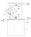
- FIG. 1 is a diagram illustrating a schematic configuration of an articulated robot according to a first embodiment of the present invention. It is the figure which abbreviate
- FIG. 1 is a diagram showing a schematic configuration of this articulated robot.
- the articulated robot 1 includes a base unit 2 and an articulated arm 3 installed on the base unit 2.
- An end effector 4 for performing work on a work body (not shown) is mounted at the tip of the articulated arm 3.
- the base unit 2 is installed on the installation surface 5 formed of a horizontal plane.
- a controller 6 that controls the operation of the articulated robot 1 is built in the base unit 2. The controller 6 may be installed outside the base unit 2.
- a plurality of (four in this embodiment) arm portions 11 to 14 are arranged in series from the proximal end side to the distal end side.
- the base unit 2 and the most proximal arm portion 11 and the adjacent arm portions 11 to 14 are connected to each other via joint portions 21 to 24 so as to be relatively displaceable from each other.
- the end effector 4 is installed on the most distal end arm portion 14.
- the arm portions 11 to 14 are connected in order from the proximal end side to the “first arm portion 11”, “second arm portion 12”, “third arm portion 13”, and “fourth arm”.
- the first joint portion 21 to the second joint portion 22, the third joint portion 23, and the fourth joint portion 21 to 24 This is referred to as a joint 24 ".
- the first joint portion 21 that connects the base unit 2 and the first arm portion 11 has the first arm portion 11 with respect to the base unit 2 around the rotation axis 7 orthogonal to the installation surface 5. This is a rotation mechanism for relative rotation.
- the first arm unit 11 is rotationally driven by a drive source 21 a provided in the base unit 2.
- the drive source 21a is, for example, a motor.
- the second joint portion 22 that connects the first arm portion 11 and the second arm portion 12 has a second axis with respect to the first arm portion 11 around the rotation axis 8 parallel to the installation surface 5.
- This is a rotation mechanism that relatively rotates the arm unit 12.
- the second arm unit 12 is rotationally driven by a drive source 22 a provided in the first arm unit 11.
- the drive source 22a is, for example, a motor.
- the third joint portion 23 that connects the second arm portion 12 and the third arm portion 13 is a linear motion mechanism that moves the third arm portion 13 in a linear direction relative to the second arm portion 12. is there.
- the movement of the third arm unit 13 is performed by a drive source 23 a provided in the second arm unit 12.
- the drive source 23a is, for example, a linear actuator.
- the second arm portion 12 and the third arm portion 13 are provided on the same axis, and when the third arm portion 13 moves closer to the base end of the second arm portion 12, the second arm portion 12
- the third arm portion 13 is housed inside the arm portion 12 and is configured such that the third arm portion 13 protrudes from the inside of the second arm portion 12 when the arm portion 12 moves away.
- the fourth joint portion 24 that connects the third arm portion 13 and the fourth arm portion 14 is a link with two degrees of freedom for rotating the fourth arm portion 14 with respect to the third arm portion 13. Actuating device.
- the link operating device includes a parallel link mechanism 30 and a posture control drive source 31 that operates the parallel link mechanism 30.
- 3 and 4 are perspective views showing only the parallel link mechanism 30, and show different states.
- the parallel link mechanism 30 is connected to the link hub 32 on the proximal end side via the three sets of link mechanisms 34 so that the posture of the link hub 33 can be changed. .
- only one set of link mechanisms 34 is shown. The number of link mechanisms 34 may be four or more.
- Each link mechanism 34 has a proximal end side link member 35, a distal end side end link member 36, and a central link member 37, and is a four-joint link mechanism composed of four rotating pairs.
- the end link members 35 and 36 on the proximal end side and the distal end side are L-shaped, and one ends thereof are rotatably connected to the link hub 32 on the proximal end side and the link hub 33 on the distal end side, respectively.
- the central link member 37 has both ends connected to the other ends of the end link members 35 and 36 on the proximal end side and the distal end side in a freely rotatable manner.
- the parallel link mechanism 30 has a structure in which two spherical link mechanisms are combined.
- the rotation pair of the proximal side link hub 32 and the proximal side end link member 35 and the central axis of each rotation pair of the proximal side end link member 35 and the central link member 37 are It intersects at the spherical link center PA (FIG. 2).
- the central axis of each rotational pair of the distal end side link hub 33 and the distal end side end link member 36 and each rotational pair of the distal end side end link member 36 and the central link member 37 are spherical surfaces on the distal end side. It intersects at the link center PB (FIG. 2).
- each rotation pair of the link hub 32 on the base end side and the end link member 35 on the base end side and the spherical link center PA on the base end side is the same, and the end link member 35 on the base end side is the same.
- the distance between each rotation pair of the central link member 37 and the spherical link center PA on the base end side is also the same.
- the distance between each rotation pair of the link hub 33 on the distal end side and the end link member 36 on the distal end side and the spherical link center PB on the distal end side is the same as each other.
- the distance between each rotation pair of the member 37 and the spherical link center PB on the tip side is also the same.
- the central axis of each rotational pair of the end link members 35 and 36 on the proximal end side and the distal end side and the central link member 37 may have a certain crossing angle ⁇ (FIG. 2) or may be parallel. Good.
- FIG. 5 is a cross-sectional view of the link hub 32 on the base end side, the end link member 35 on the base end side, and the like.
- FIG. 5 shows the relationship between the center axis O1 of each rotation pair of the base end side link hub 32 and the base end side end link member 35 and the base end side spherical link center PA.
- the positional relationship between the distal end side link hub 33 and the distal end side end link member 36 is also the same as that in FIG. 5 (not shown).
- the center axis O1 of each rotation pair of the base end side link hub 32 and the base end side end link member 35, and each rotation of the base end side end link member 35 and the central link member 37 is 90 °, the angle ⁇ may be other than 90 °.
- the three sets of link mechanisms 34 have the same geometric shape.
- the geometrically identical shape is represented by a geometric model in which each link member 35, 36, 37 is represented by a straight line, that is, each rotational pair and a straight line connecting these rotational pairs.
- a model says that the base end side part and front end side part with respect to the center part of the center link member 37 are symmetrical shapes.
- FIG. 6 is a diagram representing a set of link mechanisms 34 by straight lines.
- the parallel link mechanism 30 of this embodiment is a rotationally symmetric type, and includes a proximal end side link hub 32 and a proximal end side end link member 35, a distal end side link hub 33 and a distal end side end link member 36.
- the positional relationship is such that the positional relationship is rotationally symmetric with respect to the center line C of the central link member 37.
- the central part of each central link member 37 is located on a common track circle D.
- the link hub 32 on the proximal end side, the link hub 33 on the distal end side, and the three sets of link mechanisms 34 allow the link hub 33 on the distal end side to rotate about two orthogonal axes with respect to the link hub 32 on the proximal end side.
- the degree mechanism is configured.
- the position of the link hub 33 on the distal end side with respect to the link hub 32 on the proximal end side is a mechanism whose posture can be freely changed with two degrees of freedom.
- this two-degree-of-freedom mechanism is compact, the movable range of the link hub 33 on the distal end side with respect to the link hub 32 on the proximal end side can be widened.
- each rotation pair of the proximal and distal link hubs 32 and 33 and the proximal and distal end link members 35 and 36 passes through the spherical link centers PA and PB on the proximal and distal ends.
- the straight lines intersecting the central axis O1 (FIG. 5) at right angles are the central axes QA and QB of the link hubs 32 and 33 on the proximal end side and the distal end side
- the maximum value of the bending angle ⁇ (FIG. 6) with respect to the center axis QB of the link hub 33 can be about ⁇ 90 °.
- the turning angle ⁇ (FIG. 6) of the distal end side link hub 33 with respect to the proximal end side link hub 32 can be set in a range of 0 ° to 360 °.
- the bending angle ⁇ is a vertical angle at which the central axis QB of the distal link hub 33 is inclined with respect to the central axis QA of the proximal link hub 32.
- the turning angle ⁇ is a horizontal angle at which the central axis QB of the distal link hub 33 is inclined with respect to the central axis QA of the proximal link hub 32.
- the posture change of the distal end side link hub 33 with respect to the proximal end side link hub 32 is performed with an intersection O between the central axis QA of the proximal end side link hub 32 and the central axis QB of the distal end side link hub 33 as a rotation center.
- Is called. 3 shows a state in which the central axis QA of the link hub 32 on the proximal end side and the central axis QB of the link hub 33 on the distal end side are on the same line
- FIG. 4 shows the central axis QA of the link hub 32 on the proximal end side.
- a state in which the central axis QB of the link hub 33 on the distal end side takes an arbitrary operating angle is shown. Even if the posture changes, the distance L (FIG. 6) between the spherical link centers PA and PB on the proximal end side and the distal end side does not change.
- the link hub 32 on the base end side includes a base end member 40 fixed to the third arm portion 13 and three rotations provided integrally with the base end member 40.
- the base end member 40 has a circular through hole 40a at the center, and three rotary shaft coupling members 41 are arranged at equal intervals in the circumferential direction around the through hole 40a.
- the center of the through hole 40a is located on the central axis QA of the link hub 32 on the proximal end side.
- a rotating shaft 42 whose shaft center intersects the central axis QA of the link hub 32 on the proximal end side is rotatably connected to each rotating shaft connecting member 41.
- One end of an end link member 35 on the base end side is connected to the rotating shaft 42.
- the rotary shaft 42 is rotatably supported by the rotary shaft connecting member 41 via two bearings 43.
- the bearing 43 is a ball bearing such as a deep groove ball bearing or an angular ball bearing. These bearings 43 are fitted into an inner diameter hole 44 provided in the rotary shaft connecting member 41 and are fixed by a method such as press-fitting, adhesion, or caulking. The same applies to the types and installation methods of the bearings provided in other rotating pairs.
- the rotating shaft 42 is coupled with one end of an end link member 35 on the base end side and a fan-shaped bevel gear 45 described later so as to rotate integrally with the rotating shaft 42.
- a notch 46 is formed at one end of the base end side end link member 35, and both side portions of the notch 46 constitute inner and outer rotary shaft support portions 47 and 48.
- a rotary shaft connecting member 41 is disposed between the inner and outer rotary shaft support portions 47 and 48.
- the bevel gear 45 is disposed in contact with the inner surface of the inner rotary shaft support 47.
- the rotation shaft 42 includes a through hole formed in the bevel gear 45, a through hole formed in the inner rotation shaft support portion 47, an inner ring of the bearing 43, and a through hole formed in the outer rotation shaft support portion 48.
- the nut 50 is screwed into the threaded portion 42 b at the tip of the rotating shaft 42. Thereby, the head 42a of the rotating shaft 42 and the nut 50 sandwich the bevel gear 45, the inner and outer rotating shaft support portions 47 and 48, and the inner ring of the bearing 43, and are coupled to each other.
- Spacers 51 and 52 are interposed between the inner and outer rotary shaft support portions 47 and 48 and the bearing 43, and a preload is applied to the bearing 43 by screwing the nut 50.
- the rotating shaft 55 is coupled to the other end of the end link member 35 on the base end side.
- the rotary shaft 55 is rotatably connected to one end of the central link member 37 via two bearings 53.
- a notch 56 is formed at the other end of the base end side end link member 35, and both side portions of the notch 56 constitute inner and outer rotary shaft support portions 57 and 58.
- One end of the central link member 37 is disposed between the inner and outer rotary shaft support portions 57 and 58.
- the rotating shaft 55 is inserted from the outside through the through hole formed in the outer rotating shaft support portion 58, the inner ring of the bearing 53, and the through hole formed in the inner rotating shaft support portion 57 in this order.
- a nut 60 is screwed onto the screw portion 55b.
- the inner and outer rotary shaft support portions 57 and 58 and the inner ring of the bearing 53 are held between the head portion 55a of the rotary shaft 55 and the nut 60 and are coupled to each other.
- Spacers 61 and 62 are interposed between the inner and outer rotary shaft support portions 57 and 58 and the bearing 53, and a preload is applied to the bearing 53 by screwing the nut 60.
- the link hub 33 on the distal end side is provided with a distal end member 70 fixed to the fourth arm portion 14, and 3 provided on the inner surface of the distal end member 70 at equal intervals in the circumferential direction.
- Individual rotating shaft connecting members 71 The center of the circumference where each rotary shaft connecting member 71 is arranged is located on the central axis QB of the link hub 33 on the distal end side.
- a rotary shaft 73 is rotatably connected to each rotary shaft connecting member 71. The axis of the rotation shaft 73 intersects the center axis QB of the link hub 33 on the distal end side.
- One end of the end link member 36 on the front end side is connected to the rotation shaft 73 of the link hub 33 on the front end side.
- a rotating shaft 75 is connected to the other end of the end link member 36 on the front end side.
- the rotating shaft 75 is rotatably connected to the other end of the central link member 37.
- the rotary shaft 73 of the link hub 33 on the distal end side and the rotary shaft 75 of the central link member 37 are respectively connected to the rotary shaft connecting member 71 via two bearings (not shown) in the same manner as the rotary shafts 42 and 55 described above.
- the other end of the center link member 37 is rotatably connected to each other.
- the attitude control drive source 31 for operating the parallel link mechanism 30 is installed on the base end member 40 and is arranged inside the third arm portion 13.
- the number of posture control drive sources 31 is three, which is the same as the number of link mechanisms 34.
- the attitude control drive source 31 is a rotary actuator.
- the same number of attitude control drive sources 31 as the link mechanisms 34 are provided. However, as long as at least two of the three sets of link mechanisms 34 are provided with the attitude control drive sources 31.
- the posture of the distal end side link hub 33 with respect to the proximal end side link hub 32 can be determined.
- 4th joint part 24 consisting of a link actuating device operates parallel link mechanism 30 by rotationally driving each attitude control drive source 31. Specifically, when the attitude control drive source 31 is rotationally driven, the rotation is transmitted to the rotary shaft 42 via a pair of bevel gears 76 and 45, and the proximal end side link member with respect to the proximal end side link hub 32. The angle of 35 changes. As a result, the position and posture of the distal end side link hub 33 relative to the proximal end side link hub 32 are determined. Here, the angle of the end link member 35 on the base end side is changed using the bevel gears 76 and 45, but other mechanisms (for example, a spur gear or a worm mechanism) may be used.
- each attitude control drive source 31 is provided with torque detection means 78 for detecting the torque applied to the attitude control drive source 31.
- the detection signal of the torque detection means 78 is transmitted to the load estimation means 79 in the controller 6.
- the load estimating means 79 estimates the load acting on the distal end side link hub 33 from the detection results of the torque detecting means 78.
- the tip arm rotation mechanism 80 is provided in the fourth arm portion 14, and the end effector 4 is supported via the tip rotation mechanism 80.
- the tip rotation mechanism 80 includes a rotation drive source 80a such as a motor, and an end effector installation member 80b attached to the rotation shaft of the rotation drive source 80a.
- the end effector 4 is fixed to the end effector installation member 80b.
- the end effector 4 for example, a hand, a welding machine, a coating machine, or the like is used, but the end effector 4 is not limited to these.
- This multi-joint robot 1 has one degree of freedom of the first joint portion 21 composed of a rotation mechanism, one degree of freedom of the second joint portion 22 composed of a rotation mechanism, and one of the third joint portion 23 composed of a linear motion mechanism.
- the configuration is a total of 6 degrees of freedom, including a degree of freedom, 2 degrees of freedom of the fourth joint portion 24 formed of a link actuating device, and 1 degree of freedom of the tip rotation mechanism 80 provided in the fourth arm portion 14. With a 6-degree-of-freedom configuration, it is possible to approximate the movement of a human hand.
- a link actuator for one of the plurality of joints 21 to 24 by using a link actuator for one of the plurality of joints 21 to 24, a smooth operation having no singular point is possible within the operation range of 90 ° of bending angle and 360 ° of turning.
- the fine motion is, for example, a motion that moves around a human wrist joint, such as a character writing motion or a motion using a snap.
- detailed operations are not limited to these operations.
- the joint portion 24 can be made compact while having two degrees of freedom of rotation.
- Torque detection means 78 for detecting the torque applied to each posture control drive source 31 and load estimation means 79 for estimating the load acting on the distal end side link hub 33 from the detection result of the torque detection means 78 are provided. Yes. For this reason, when an abnormal load is applied to the multi-joint robot 1, for example, when it collides with a person or an object, this can be detected. For this reason, when an abnormal load is applied, it is possible to take an avoidance operation such as stopping the operation, which is safe.
- the torque detection means 78 in the attitude control drive source 31 it is possible to estimate the load acting on the link hub 33 on the distal end side without providing a load detection sensor separately. As a result, the articulated robot 1 can be made compact and cost reduced. In addition, since there is no singular point and the structure can be moved smoothly in all directions within the operating range of the fourth joint portion 24 composed of the link operating device, when loads are applied to the link hub 33 on the distal end side from various directions. However, torque is reliably transmitted to the attitude control drive source 31. Thereby, an accurate load can be estimated.
- the fourth joint portion 24 corresponding to the wrist joint is a two-degree-of-freedom link actuating device capable of operating close to the wrist joint. It is composed. For this reason, it becomes easier to imagine the relationship between the movement of each joint portion 21 to 24 and the movement of the end effector 4, and the operability is good.
- the fourth joint portion 24 formed of the link actuator is disposed near the tip of the multi-joint arm 3, the load acting on the link actuator is small, and higher speed and finer operation is possible.
- distal end rotation mechanism 80 that may twist the cable is arranged on the distal end side with respect to the fourth joint portion 24 composed of the link actuating device and the third joint portion 23 composed of the linear motion mechanism, the link operation is performed. Wiring of devices, linear motion mechanisms, etc. is easy.
- the third arm portion 13 is housed inside the second arm portion 12. For this reason, when the articulated robot 1 is not used, it can be made compact and the storage space can be narrow. Further, since the movable range of the entire articulated robot 1, particularly the movable range of the articulated arm 3 between the base unit 2 and the end effector 4 can be minimized, the occupied space can be reduced.
- FIG. 7 shows a second embodiment.
- the multi-joint robot 1 of the second embodiment is different from the first embodiment of FIG. 1 in the third joint portion 23 formed of a linear motion mechanism.
- the third arm unit 13 moves along the linear stage 23 b installed on the side surface of the second arm unit 12.
- the driving of the third arm unit 13 is performed by a driving source 23 c provided in the second arm unit 12.
- the drive source 23c is, for example, a linear actuator.
- Other configurations are the same as those of the articulated robot 1 of the first embodiment shown in FIG.
- FIG. 8 further shows a third embodiment.
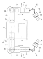
- the articulated robot 1 of the third embodiment two articulated arms 3 are installed in one base unit 2.
- the first arm portions 11 of the two articulated arms 3 are installed on side surfaces of the base unit 2 that are symmetrical to each other.
- the configuration of each articulated arm 3 is the same as the articulated arm 3 of the articulated robot 1 of the first embodiment shown in FIG.
- FIG. 9 further shows a fourth embodiment.
- the second joint portion 22 of the articulated arm 3 is replaced with a rotation mechanism of the articulated robot 1 of the first embodiment of FIG.
- the structure of the other joint parts 21, 23, and 24 is the same as that of the articulated robot of the first embodiment shown in FIG. Since the second joint portion 22 has two degrees of freedom, the multi-joint arm 3 itself has a configuration of six degrees of freedom.
- the tip arm rotation mechanism (not shown) is provided on the fourth arm portion 14, the entire articulated robot 1 has a configuration of 7 degrees of freedom.
Landscapes
- Engineering & Computer Science (AREA)
- Robotics (AREA)
- Mechanical Engineering (AREA)
- Manipulator (AREA)
Abstract
Le robot articulé (1) de l'invention possède une unité de base (2) et un bras articulé (3). Le bras articulé (3) est tel qu'une pluralité de parties bras (11 à 14) est rangée en série du côté extrémité de base vers le côté extrémité avant, et l'unité de base (2) avec la partie bras (11) du côté le plus à l'extrémité de base, ainsi que les parties bras (11 à 14) adjacentes entre elles sont raccordées individuellement par l'intermédiaire de parties joint (21 à 24), et de manière à permettre un déplacement relatif entre elles. Un organe effecteur (4) est monté sur la partie bras (14) du côté le plus à l'extrémité avant. Au moins une partie joint (24) est constituée par le dispositif de fonctionnement de liaison qui met en rotation relative les parties bras (13, 14) des deux côtés de la partie joint (24) entre elles autour de deux axes perpendiculaires entre eux, et au moins une partie joint (23) est constituée par un mécanisme à mouvement linéaire déplaçant de manière relative les parties bras (12, 13) des deux côtés l'une par rapport à l'autre dans la direction d'une droite.
Applications Claiming Priority (2)
| Application Number | Priority Date | Filing Date | Title |
|---|---|---|---|
| JP2015-025926 | 2015-02-13 | ||
| JP2015025926A JP6576646B2 (ja) | 2015-02-13 | 2015-02-13 | リンク作動装置を用いた多関節ロボット |
Publications (1)
| Publication Number | Publication Date |
|---|---|
| WO2016129623A1 true WO2016129623A1 (fr) | 2016-08-18 |
Family
ID=56614673
Family Applications (1)
| Application Number | Title | Priority Date | Filing Date |
|---|---|---|---|
| PCT/JP2016/053901 Ceased WO2016129623A1 (fr) | 2015-02-13 | 2016-02-10 | Robot articulé mettant en œuvre un dispositif de fonctionnement de liaison |
Country Status (2)
| Country | Link |
|---|---|
| JP (1) | JP6576646B2 (fr) |
| WO (1) | WO2016129623A1 (fr) |
Cited By (1)
| Publication number | Priority date | Publication date | Assignee | Title |
|---|---|---|---|---|
| CN112739506A (zh) * | 2018-09-28 | 2021-04-30 | Ntn株式会社 | 连杆促动装置 |
Families Citing this family (5)
| Publication number | Priority date | Publication date | Assignee | Title |
|---|---|---|---|---|
| JP2018075689A (ja) * | 2016-11-11 | 2018-05-17 | Ntn株式会社 | 作動装置および双腕型作動装置 |
| JP2018167350A (ja) * | 2017-03-29 | 2018-11-01 | Ntn株式会社 | 多関節ロボット |
| JP2019063902A (ja) * | 2017-09-29 | 2019-04-25 | Ntn株式会社 | 多関節ロボットおよびその操作方法 |
| JP7192016B2 (ja) * | 2021-03-25 | 2022-12-19 | Ntn株式会社 | 球面リンク機構および球面リンク作動装置 |
| WO2025046713A1 (fr) * | 2023-08-28 | 2025-03-06 | F.Med株式会社 | Manipulateur de travail et système comprenant un manipulateur de travail |
Citations (5)
| Publication number | Priority date | Publication date | Assignee | Title |
|---|---|---|---|---|
| JPS60249588A (ja) * | 1984-05-24 | 1985-12-10 | 住友電気工業株式会社 | 位置決め機構 |
| JPH09314305A (ja) * | 1996-05-31 | 1997-12-09 | Ube Ind Ltd | 金型スプレイロボット |
| JPH10118971A (ja) * | 1996-10-16 | 1998-05-12 | Ricoh Co Ltd | マニプレータ |
| WO2013190639A1 (fr) * | 2012-06-19 | 2013-12-27 | 株式会社安川電機 | Système robotique et procédé de fabrication de biens traités |
| WO2014185373A1 (fr) * | 2013-05-16 | 2014-11-20 | Ntn株式会社 | Dispositif d'actionnement de liaison |
Family Cites Families (7)
| Publication number | Priority date | Publication date | Assignee | Title |
|---|---|---|---|---|
| US4762455A (en) * | 1987-06-01 | 1988-08-09 | Remote Technology Corporation | Remote manipulator |
| JP2000130536A (ja) * | 1998-10-27 | 2000-05-12 | Fanuc Ltd | パラレルリンク機構 |
| JP2005088095A (ja) * | 2003-09-12 | 2005-04-07 | Denso Corp | 車載ロボットハンド |
| JP2005127475A (ja) * | 2003-10-27 | 2005-05-19 | Ntn Corp | リンク作動装置 |
| WO2008052581A1 (fr) * | 2006-10-31 | 2008-05-08 | Force Dimension S.A.R.L. | Structure cinématique parallèle |
| JP2010260139A (ja) * | 2009-05-08 | 2010-11-18 | Ntn Corp | 遠隔操作型加工ロボット |
| JP5682642B2 (ja) * | 2013-03-05 | 2015-03-11 | 株式会社安川電機 | パラレルリンクロボット |
-
2015
- 2015-02-13 JP JP2015025926A patent/JP6576646B2/ja active Active
-
2016
- 2016-02-10 WO PCT/JP2016/053901 patent/WO2016129623A1/fr not_active Ceased
Patent Citations (5)
| Publication number | Priority date | Publication date | Assignee | Title |
|---|---|---|---|---|
| JPS60249588A (ja) * | 1984-05-24 | 1985-12-10 | 住友電気工業株式会社 | 位置決め機構 |
| JPH09314305A (ja) * | 1996-05-31 | 1997-12-09 | Ube Ind Ltd | 金型スプレイロボット |
| JPH10118971A (ja) * | 1996-10-16 | 1998-05-12 | Ricoh Co Ltd | マニプレータ |
| WO2013190639A1 (fr) * | 2012-06-19 | 2013-12-27 | 株式会社安川電機 | Système robotique et procédé de fabrication de biens traités |
| WO2014185373A1 (fr) * | 2013-05-16 | 2014-11-20 | Ntn株式会社 | Dispositif d'actionnement de liaison |
Cited By (2)
| Publication number | Priority date | Publication date | Assignee | Title |
|---|---|---|---|---|
| CN112739506A (zh) * | 2018-09-28 | 2021-04-30 | Ntn株式会社 | 连杆促动装置 |
| US12042935B2 (en) | 2018-09-28 | 2024-07-23 | Ntn Corporation | Link actuation apparatus |
Also Published As
| Publication number | Publication date |
|---|---|
| JP6576646B2 (ja) | 2019-09-18 |
| JP2016147350A (ja) | 2016-08-18 |
Similar Documents
| Publication | Publication Date | Title |
|---|---|---|
| JP6502115B2 (ja) | リンク作動装置を用いた多関節ロボット | |
| WO2016129623A1 (fr) | Robot articulé mettant en œuvre un dispositif de fonctionnement de liaison | |
| JP5951224B2 (ja) | リンク作動装置の原点位置初期設定方法およびリンク作動装置 | |
| EP3446836B1 (fr) | Dispositif de travail et dispositif de travail à double bras | |
| JP6883073B2 (ja) | リンク作動装置を用いた多関節ロボット | |
| US11420322B2 (en) | Working device and double-arm type working device | |
| JP7022008B2 (ja) | リンク作動装置 | |
| US20160361816A1 (en) | Device and method for controlling link actuation device | |
| JP6625322B2 (ja) | リンク作動装置 | |
| JP6602620B2 (ja) | 組合せ型リンク作動装置 | |
| US11130225B2 (en) | Working device and double-arm type working device | |
| WO2016021099A1 (fr) | Robot à tringles parallèles et structure à tringles parallèles | |
| JP2018167350A (ja) | 多関節ロボット | |
| JP2026032256A (ja) | パラレルリンク機構およびリンク作動装置 | |
| WO2018088446A1 (fr) | Dispositif de travail et dispositif de travail du type à deux bras | |
| WO2016084685A1 (fr) | Appareil de travail employant un mécanisme de liaison parallèle | |
| JP6792687B2 (ja) | リンク作動装置 | |
| JP2016153159A (ja) | パラレルリンク機構を用いた作業装置 | |
| JP2018167365A (ja) | ロボットアーム | |
| WO2016080472A1 (fr) | Dispositif de travail utilisant un mécanisme à liaisons parallèles | |
| JP6976098B2 (ja) | リンク作動式作業装置 |
Legal Events
| Date | Code | Title | Description |
|---|---|---|---|
| 121 | Ep: the epo has been informed by wipo that ep was designated in this application |
Ref document number: 16749266 Country of ref document: EP Kind code of ref document: A1 |
|
| NENP | Non-entry into the national phase |
Ref country code: DE |
|
| 122 | Ep: pct application non-entry in european phase |
Ref document number: 16749266 Country of ref document: EP Kind code of ref document: A1 |