WO2016132916A1 - 網目状樹脂成形品 - Google Patents
網目状樹脂成形品 Download PDFInfo
- Publication number
- WO2016132916A1 WO2016132916A1 PCT/JP2016/053319 JP2016053319W WO2016132916A1 WO 2016132916 A1 WO2016132916 A1 WO 2016132916A1 JP 2016053319 W JP2016053319 W JP 2016053319W WO 2016132916 A1 WO2016132916 A1 WO 2016132916A1
- Authority
- WO
- WIPO (PCT)
- Prior art keywords
- resin
- mesh
- molded product
- resin molded
- resin linear
- Prior art date
- Legal status (The legal status is an assumption and is not a legal conclusion. Google has not performed a legal analysis and makes no representation as to the accuracy of the status listed.)
- Ceased
Links
Images






Classifications
-
- B—PERFORMING OPERATIONS; TRANSPORTING
- B29—WORKING OF PLASTICS; WORKING OF SUBSTANCES IN A PLASTIC STATE IN GENERAL
- B29C—SHAPING OR JOINING OF PLASTICS; SHAPING OF MATERIAL IN A PLASTIC STATE, NOT OTHERWISE PROVIDED FOR; AFTER-TREATMENT OF THE SHAPED PRODUCTS, e.g. REPAIRING
- B29C48/00—Extrusion moulding, i.e. expressing the moulding material through a die or nozzle which imparts the desired form; Apparatus therefor
- B29C48/001—Combinations of extrusion moulding with other shaping operations
- B29C48/0018—Combinations of extrusion moulding with other shaping operations combined with shaping by orienting, stretching or shrinking, e.g. film blowing
-
- B—PERFORMING OPERATIONS; TRANSPORTING
- B29—WORKING OF PLASTICS; WORKING OF SUBSTANCES IN A PLASTIC STATE IN GENERAL
- B29C—SHAPING OR JOINING OF PLASTICS; SHAPING OF MATERIAL IN A PLASTIC STATE, NOT OTHERWISE PROVIDED FOR; AFTER-TREATMENT OF THE SHAPED PRODUCTS, e.g. REPAIRING
- B29C48/00—Extrusion moulding, i.e. expressing the moulding material through a die or nozzle which imparts the desired form; Apparatus therefor
- B29C48/03—Extrusion moulding, i.e. expressing the moulding material through a die or nozzle which imparts the desired form; Apparatus therefor characterised by the shape of the extruded material at extrusion
- B29C48/09—Articles with cross-sections having partially or fully enclosed cavities, e.g. pipes or channels
- B29C48/10—Articles with cross-sections having partially or fully enclosed cavities, e.g. pipes or channels flexible, e.g. blown foils
-
- B—PERFORMING OPERATIONS; TRANSPORTING
- B29—WORKING OF PLASTICS; WORKING OF SUBSTANCES IN A PLASTIC STATE IN GENERAL
- B29C—SHAPING OR JOINING OF PLASTICS; SHAPING OF MATERIAL IN A PLASTIC STATE, NOT OTHERWISE PROVIDED FOR; AFTER-TREATMENT OF THE SHAPED PRODUCTS, e.g. REPAIRING
- B29C48/00—Extrusion moulding, i.e. expressing the moulding material through a die or nozzle which imparts the desired form; Apparatus therefor
- B29C48/16—Articles comprising two or more components, e.g. co-extruded layers
-
- B—PERFORMING OPERATIONS; TRANSPORTING
- B29—WORKING OF PLASTICS; WORKING OF SUBSTANCES IN A PLASTIC STATE IN GENERAL
- B29C—SHAPING OR JOINING OF PLASTICS; SHAPING OF MATERIAL IN A PLASTIC STATE, NOT OTHERWISE PROVIDED FOR; AFTER-TREATMENT OF THE SHAPED PRODUCTS, e.g. REPAIRING
- B29C48/00—Extrusion moulding, i.e. expressing the moulding material through a die or nozzle which imparts the desired form; Apparatus therefor
- B29C48/25—Component parts, details or accessories; Auxiliary operations
- B29C48/30—Extrusion nozzles or dies
- B29C48/301—Extrusion nozzles or dies having reciprocating, oscillating or rotating parts
-
- B—PERFORMING OPERATIONS; TRANSPORTING
- B29—WORKING OF PLASTICS; WORKING OF SUBSTANCES IN A PLASTIC STATE IN GENERAL
- B29C—SHAPING OR JOINING OF PLASTICS; SHAPING OF MATERIAL IN A PLASTIC STATE, NOT OTHERWISE PROVIDED FOR; AFTER-TREATMENT OF THE SHAPED PRODUCTS, e.g. REPAIRING
- B29C48/00—Extrusion moulding, i.e. expressing the moulding material through a die or nozzle which imparts the desired form; Apparatus therefor
- B29C48/25—Component parts, details or accessories; Auxiliary operations
- B29C48/30—Extrusion nozzles or dies
- B29C48/345—Extrusion nozzles comprising two or more adjacently arranged ports, for simultaneously extruding multiple strands, e.g. for pelletising
-
- B—PERFORMING OPERATIONS; TRANSPORTING
- B29—WORKING OF PLASTICS; WORKING OF SUBSTANCES IN A PLASTIC STATE IN GENERAL
- B29C—SHAPING OR JOINING OF PLASTICS; SHAPING OF MATERIAL IN A PLASTIC STATE, NOT OTHERWISE PROVIDED FOR; AFTER-TREATMENT OF THE SHAPED PRODUCTS, e.g. REPAIRING
- B29C48/00—Extrusion moulding, i.e. expressing the moulding material through a die or nozzle which imparts the desired form; Apparatus therefor
- B29C48/25—Component parts, details or accessories; Auxiliary operations
- B29C48/78—Thermal treatment of the extrusion moulding material or of preformed parts or layers, e.g. by heating or cooling
-
- B—PERFORMING OPERATIONS; TRANSPORTING
- B29—WORKING OF PLASTICS; WORKING OF SUBSTANCES IN A PLASTIC STATE IN GENERAL
- B29C—SHAPING OR JOINING OF PLASTICS; SHAPING OF MATERIAL IN A PLASTIC STATE, NOT OTHERWISE PROVIDED FOR; AFTER-TREATMENT OF THE SHAPED PRODUCTS, e.g. REPAIRING
- B29C55/00—Shaping by stretching, e.g. drawing through a die; Apparatus therefor
- B29C55/22—Shaping by stretching, e.g. drawing through a die; Apparatus therefor of tubes
-
- B—PERFORMING OPERATIONS; TRANSPORTING
- B29—WORKING OF PLASTICS; WORKING OF SUBSTANCES IN A PLASTIC STATE IN GENERAL
- B29C—SHAPING OR JOINING OF PLASTICS; SHAPING OF MATERIAL IN A PLASTIC STATE, NOT OTHERWISE PROVIDED FOR; AFTER-TREATMENT OF THE SHAPED PRODUCTS, e.g. REPAIRING
- B29C55/00—Shaping by stretching, e.g. drawing through a die; Apparatus therefor
- B29C55/22—Shaping by stretching, e.g. drawing through a die; Apparatus therefor of tubes
- B29C55/24—Shaping by stretching, e.g. drawing through a die; Apparatus therefor of tubes radial
-
- B—PERFORMING OPERATIONS; TRANSPORTING
- B29—WORKING OF PLASTICS; WORKING OF SUBSTANCES IN A PLASTIC STATE IN GENERAL
- B29D—PRODUCING PARTICULAR ARTICLES FROM PLASTICS OR FROM SUBSTANCES IN A PLASTIC STATE
- B29D23/00—Producing tubular articles
-
- B—PERFORMING OPERATIONS; TRANSPORTING
- B29—WORKING OF PLASTICS; WORKING OF SUBSTANCES IN A PLASTIC STATE IN GENERAL
- B29D—PRODUCING PARTICULAR ARTICLES FROM PLASTICS OR FROM SUBSTANCES IN A PLASTIC STATE
- B29D28/00—Producing nets or the like, e.g. meshes, lattices
-
- B—PERFORMING OPERATIONS; TRANSPORTING
- B32—LAYERED PRODUCTS
- B32B—LAYERED PRODUCTS, i.e. PRODUCTS BUILT-UP OF STRATA OF FLAT OR NON-FLAT, e.g. CELLULAR OR HONEYCOMB, FORM
- B32B1/00—Layered products having a non-planar shape
- B32B1/08—Tubular products
-
- B—PERFORMING OPERATIONS; TRANSPORTING
- B32—LAYERED PRODUCTS
- B32B—LAYERED PRODUCTS, i.e. PRODUCTS BUILT-UP OF STRATA OF FLAT OR NON-FLAT, e.g. CELLULAR OR HONEYCOMB, FORM
- B32B15/00—Layered products comprising a layer of metal
- B32B15/14—Layered products comprising a layer of metal next to a fibrous or filamentary layer
-
- B—PERFORMING OPERATIONS; TRANSPORTING
- B32—LAYERED PRODUCTS
- B32B—LAYERED PRODUCTS, i.e. PRODUCTS BUILT-UP OF STRATA OF FLAT OR NON-FLAT, e.g. CELLULAR OR HONEYCOMB, FORM
- B32B25/00—Layered products comprising a layer of natural or synthetic rubber
- B32B25/10—Layered products comprising a layer of natural or synthetic rubber next to a fibrous or filamentary layer
-
- B—PERFORMING OPERATIONS; TRANSPORTING
- B32—LAYERED PRODUCTS
- B32B—LAYERED PRODUCTS, i.e. PRODUCTS BUILT-UP OF STRATA OF FLAT OR NON-FLAT, e.g. CELLULAR OR HONEYCOMB, FORM
- B32B27/00—Layered products comprising a layer of synthetic resin
- B32B27/12—Layered products comprising a layer of synthetic resin next to a fibrous or filamentary layer
-
- B—PERFORMING OPERATIONS; TRANSPORTING
- B32—LAYERED PRODUCTS
- B32B—LAYERED PRODUCTS, i.e. PRODUCTS BUILT-UP OF STRATA OF FLAT OR NON-FLAT, e.g. CELLULAR OR HONEYCOMB, FORM
- B32B5/00—Layered products characterised by the non- homogeneity or physical structure, i.e. comprising a fibrous, filamentary, particulate or foam layer; Layered products characterised by having a layer differing constitutionally or physically in different parts
- B32B5/02—Layered products characterised by the non- homogeneity or physical structure, i.e. comprising a fibrous, filamentary, particulate or foam layer; Layered products characterised by having a layer differing constitutionally or physically in different parts characterised by structural features of a fibrous or filamentary layer
- B32B5/028—Net structure, e.g. spaced apart filaments bonded at the crossing points
-
- F—MECHANICAL ENGINEERING; LIGHTING; HEATING; WEAPONS; BLASTING
- F16—ENGINEERING ELEMENTS AND UNITS; GENERAL MEASURES FOR PRODUCING AND MAINTAINING EFFECTIVE FUNCTIONING OF MACHINES OR INSTALLATIONS; THERMAL INSULATION IN GENERAL
- F16L—PIPES; JOINTS OR FITTINGS FOR PIPES; SUPPORTS FOR PIPES, CABLES OR PROTECTIVE TUBING; MEANS FOR THERMAL INSULATION IN GENERAL
- F16L11/00—Hoses, i.e. flexible pipes
- F16L11/04—Hoses, i.e. flexible pipes made of rubber or flexible plastics
- F16L11/08—Hoses, i.e. flexible pipes made of rubber or flexible plastics with reinforcements embedded in the wall
- F16L11/081—Hoses, i.e. flexible pipes made of rubber or flexible plastics with reinforcements embedded in the wall comprising one or more layers of a helically wound cord or wire
- F16L11/082—Hoses, i.e. flexible pipes made of rubber or flexible plastics with reinforcements embedded in the wall comprising one or more layers of a helically wound cord or wire two layers
-
- F—MECHANICAL ENGINEERING; LIGHTING; HEATING; WEAPONS; BLASTING
- F16—ENGINEERING ELEMENTS AND UNITS; GENERAL MEASURES FOR PRODUCING AND MAINTAINING EFFECTIVE FUNCTIONING OF MACHINES OR INSTALLATIONS; THERMAL INSULATION IN GENERAL
- F16L—PIPES; JOINTS OR FITTINGS FOR PIPES; SUPPORTS FOR PIPES, CABLES OR PROTECTIVE TUBING; MEANS FOR THERMAL INSULATION IN GENERAL
- F16L11/00—Hoses, i.e. flexible pipes
- F16L11/04—Hoses, i.e. flexible pipes made of rubber or flexible plastics
- F16L11/10—Hoses, i.e. flexible pipes made of rubber or flexible plastics with reinforcements not embedded in the wall
-
- B—PERFORMING OPERATIONS; TRANSPORTING
- B29—WORKING OF PLASTICS; WORKING OF SUBSTANCES IN A PLASTIC STATE IN GENERAL
- B29C—SHAPING OR JOINING OF PLASTICS; SHAPING OF MATERIAL IN A PLASTIC STATE, NOT OTHERWISE PROVIDED FOR; AFTER-TREATMENT OF THE SHAPED PRODUCTS, e.g. REPAIRING
- B29C2793/00—Shaping techniques involving a cutting or machining operation
- B29C2793/0063—Cutting longitudinally
-
- B—PERFORMING OPERATIONS; TRANSPORTING
- B29—WORKING OF PLASTICS; WORKING OF SUBSTANCES IN A PLASTIC STATE IN GENERAL
- B29C—SHAPING OR JOINING OF PLASTICS; SHAPING OF MATERIAL IN A PLASTIC STATE, NOT OTHERWISE PROVIDED FOR; AFTER-TREATMENT OF THE SHAPED PRODUCTS, e.g. REPAIRING
- B29C2793/00—Shaping techniques involving a cutting or machining operation
- B29C2793/009—Shaping techniques involving a cutting or machining operation after shaping
-
- B—PERFORMING OPERATIONS; TRANSPORTING
- B29—WORKING OF PLASTICS; WORKING OF SUBSTANCES IN A PLASTIC STATE IN GENERAL
- B29C—SHAPING OR JOINING OF PLASTICS; SHAPING OF MATERIAL IN A PLASTIC STATE, NOT OTHERWISE PROVIDED FOR; AFTER-TREATMENT OF THE SHAPED PRODUCTS, e.g. REPAIRING
- B29C48/00—Extrusion moulding, i.e. expressing the moulding material through a die or nozzle which imparts the desired form; Apparatus therefor
- B29C48/03—Extrusion moulding, i.e. expressing the moulding material through a die or nozzle which imparts the desired form; Apparatus therefor characterised by the shape of the extruded material at extrusion
- B29C48/05—Filamentary, e.g. strands
-
- B—PERFORMING OPERATIONS; TRANSPORTING
- B29—WORKING OF PLASTICS; WORKING OF SUBSTANCES IN A PLASTIC STATE IN GENERAL
- B29C—SHAPING OR JOINING OF PLASTICS; SHAPING OF MATERIAL IN A PLASTIC STATE, NOT OTHERWISE PROVIDED FOR; AFTER-TREATMENT OF THE SHAPED PRODUCTS, e.g. REPAIRING
- B29C48/00—Extrusion moulding, i.e. expressing the moulding material through a die or nozzle which imparts the desired form; Apparatus therefor
- B29C48/03—Extrusion moulding, i.e. expressing the moulding material through a die or nozzle which imparts the desired form; Apparatus therefor characterised by the shape of the extruded material at extrusion
- B29C48/09—Articles with cross-sections having partially or fully enclosed cavities, e.g. pipes or channels
-
- B—PERFORMING OPERATIONS; TRANSPORTING
- B29—WORKING OF PLASTICS; WORKING OF SUBSTANCES IN A PLASTIC STATE IN GENERAL
- B29K—INDEXING SCHEME ASSOCIATED WITH SUBCLASSES B29B, B29C OR B29D, RELATING TO MOULDING MATERIALS OR TO MATERIALS FOR MOULDS, REINFORCEMENTS, FILLERS OR PREFORMED PARTS, e.g. INSERTS
- B29K2023/00—Use of polyalkenes or derivatives thereof as moulding material
- B29K2023/04—Polymers of ethylene
- B29K2023/06—PE, i.e. polyethylene
-
- B—PERFORMING OPERATIONS; TRANSPORTING
- B29—WORKING OF PLASTICS; WORKING OF SUBSTANCES IN A PLASTIC STATE IN GENERAL
- B29K—INDEXING SCHEME ASSOCIATED WITH SUBCLASSES B29B, B29C OR B29D, RELATING TO MOULDING MATERIALS OR TO MATERIALS FOR MOULDS, REINFORCEMENTS, FILLERS OR PREFORMED PARTS, e.g. INSERTS
- B29K2023/00—Use of polyalkenes or derivatives thereof as moulding material
- B29K2023/10—Polymers of propylene
- B29K2023/12—PP, i.e. polypropylene
-
- B—PERFORMING OPERATIONS; TRANSPORTING
- B29—WORKING OF PLASTICS; WORKING OF SUBSTANCES IN A PLASTIC STATE IN GENERAL
- B29K—INDEXING SCHEME ASSOCIATED WITH SUBCLASSES B29B, B29C OR B29D, RELATING TO MOULDING MATERIALS OR TO MATERIALS FOR MOULDS, REINFORCEMENTS, FILLERS OR PREFORMED PARTS, e.g. INSERTS
- B29K2067/00—Use of polyesters or derivatives thereof, as moulding material
- B29K2067/003—PET, i.e. poylethylene terephthalate
-
- B—PERFORMING OPERATIONS; TRANSPORTING
- B29—WORKING OF PLASTICS; WORKING OF SUBSTANCES IN A PLASTIC STATE IN GENERAL
- B29K—INDEXING SCHEME ASSOCIATED WITH SUBCLASSES B29B, B29C OR B29D, RELATING TO MOULDING MATERIALS OR TO MATERIALS FOR MOULDS, REINFORCEMENTS, FILLERS OR PREFORMED PARTS, e.g. INSERTS
- B29K2101/00—Use of unspecified macromolecular compounds as moulding material
- B29K2101/12—Thermoplastic materials
-
- B—PERFORMING OPERATIONS; TRANSPORTING
- B29—WORKING OF PLASTICS; WORKING OF SUBSTANCES IN A PLASTIC STATE IN GENERAL
- B29L—INDEXING SCHEME ASSOCIATED WITH SUBCLASS B29C, RELATING TO PARTICULAR ARTICLES
- B29L2023/00—Tubular articles
-
- B—PERFORMING OPERATIONS; TRANSPORTING
- B29—WORKING OF PLASTICS; WORKING OF SUBSTANCES IN A PLASTIC STATE IN GENERAL
- B29L—INDEXING SCHEME ASSOCIATED WITH SUBCLASS B29C, RELATING TO PARTICULAR ARTICLES
- B29L2028/00—Nets or the like
-
- B—PERFORMING OPERATIONS; TRANSPORTING
- B32—LAYERED PRODUCTS
- B32B—LAYERED PRODUCTS, i.e. PRODUCTS BUILT-UP OF STRATA OF FLAT OR NON-FLAT, e.g. CELLULAR OR HONEYCOMB, FORM
- B32B2262/00—Composition or structural features of fibres which form a fibrous or filamentary layer or are present as additives
- B32B2262/02—Synthetic macromolecular fibres
- B32B2262/0253—Polyolefin fibres
-
- B—PERFORMING OPERATIONS; TRANSPORTING
- B32—LAYERED PRODUCTS
- B32B—LAYERED PRODUCTS, i.e. PRODUCTS BUILT-UP OF STRATA OF FLAT OR NON-FLAT, e.g. CELLULAR OR HONEYCOMB, FORM
- B32B2262/00—Composition or structural features of fibres which form a fibrous or filamentary layer or are present as additives
- B32B2262/02—Synthetic macromolecular fibres
- B32B2262/0261—Polyamide fibres
-
- B—PERFORMING OPERATIONS; TRANSPORTING
- B32—LAYERED PRODUCTS
- B32B—LAYERED PRODUCTS, i.e. PRODUCTS BUILT-UP OF STRATA OF FLAT OR NON-FLAT, e.g. CELLULAR OR HONEYCOMB, FORM
- B32B2262/00—Composition or structural features of fibres which form a fibrous or filamentary layer or are present as additives
- B32B2262/02—Synthetic macromolecular fibres
- B32B2262/0276—Polyester fibres
- B32B2262/0284—Polyethylene terephthalate [PET] or polybutylene terephthalate [PBT]
-
- B—PERFORMING OPERATIONS; TRANSPORTING
- B32—LAYERED PRODUCTS
- B32B—LAYERED PRODUCTS, i.e. PRODUCTS BUILT-UP OF STRATA OF FLAT OR NON-FLAT, e.g. CELLULAR OR HONEYCOMB, FORM
- B32B2307/00—Properties of the layers or laminate
- B32B2307/30—Properties of the layers or laminate having particular thermal properties
- B32B2307/306—Resistant to heat
-
- B—PERFORMING OPERATIONS; TRANSPORTING
- B32—LAYERED PRODUCTS
- B32B—LAYERED PRODUCTS, i.e. PRODUCTS BUILT-UP OF STRATA OF FLAT OR NON-FLAT, e.g. CELLULAR OR HONEYCOMB, FORM
- B32B2307/00—Properties of the layers or laminate
- B32B2307/30—Properties of the layers or laminate having particular thermal properties
- B32B2307/306—Resistant to heat
- B32B2307/3065—Flame resistant or retardant, fire resistant or retardant
-
- B—PERFORMING OPERATIONS; TRANSPORTING
- B32—LAYERED PRODUCTS
- B32B—LAYERED PRODUCTS, i.e. PRODUCTS BUILT-UP OF STRATA OF FLAT OR NON-FLAT, e.g. CELLULAR OR HONEYCOMB, FORM
- B32B2307/00—Properties of the layers or laminate
- B32B2307/70—Other properties
- B32B2307/712—Weather resistant
-
- B—PERFORMING OPERATIONS; TRANSPORTING
- B32—LAYERED PRODUCTS
- B32B—LAYERED PRODUCTS, i.e. PRODUCTS BUILT-UP OF STRATA OF FLAT OR NON-FLAT, e.g. CELLULAR OR HONEYCOMB, FORM
- B32B2597/00—Tubular articles, e.g. hoses, pipes
Definitions
- the present invention relates to a reticulated resin molded product.
- a mesh-shaped resin molded product such as a mesh-shaped resin tube and a manufacturing method thereof are described in Patent Documents 1 to 3, for example.
- Patent Document 1 describes a mesh-like resin tube having a structure excellent in flexibility.
- JP 2002-181258 A JP 2002-154147 A JP-A-9-286052 JP 2008-223940 A JP-T-2002-527684 Publication
- the conventional mesh-shaped resin molded product including the mesh-shaped resin molded product described in Patent Document 1 has not been sufficiently stretchable. That is, the mesh-like resin tube described in Patent Document 1 may have a certain degree of flexibility, but is not sufficiently stretchable in the axial direction.
- conventional mesh-shaped resin molded products are used for the same purpose as that described in Patent Documents 4 and 5, for example, for the purpose of protecting bent hydraulic pipes (rubber hoses) mounted on automobiles and the like.
- the stretchability of the mesh-like resin molded product has room for improvement in terms of fitting (adhering) so as to follow the object to be protected.
- the conventional reticulated resin molded product has room for improvement in that the reticulated resin product itself is likely to be frayed when partially cut.
- the present invention A mesh-like resin molded product used for enclosing and protecting a hollow pipe member provided in a vehicle or a small ship, In a normal state where no load is applied to the mesh-shaped resin molded product, a plurality of first resin linear portions extending in parallel with each other, and in parallel with each other and with respect to each first resin linear portion A plurality of second resin linear portions extending in the intersecting direction, and each first resin linear portion and each second resin linear portion are mutually connected at a joint portion located at the intersecting portion.
- the second area which is the area of the joint between the first resin linear portion and the second resin linear portion, is smaller than the first area, which is the overlapping area between the first resin linear portion and the second resin linear portion.
- the vehicle described above may have two wheels, three wheels, or four or more wheels as long as it has an internal combustion engine.
- vehicles stipulated in the Road Traffic Law that is, automobiles having an internal combustion engine, automobiles such as electric cars, fuel cell cars and hybrid cars, bicycles with motors, light vehicles, and trolley buses
- construction vehicles, agricultural vehicles, industrial vehicles, and the like there are construction vehicles, agricultural vehicles, industrial vehicles, and the like.
- the small ship mentioned above refers to the ship of less than 20 tons. And as a small ship mentioned above, a pleasure boat, a motor boat, a hovercraft, a yacht with an engine, a water motorcycle (marine jet), etc. are mentioned.
- the reticulated resin molded product can be made excellent in stretchability.
- FIG. 1 It is a figure which shows the mesh-shaped resin molded product which concerns on 1st Embodiment, Among these, (a) is a front view, (b) is a cut end view along the AA line of (a), (c) is a figure. It is a top view of the vicinity of the cross
- the figure shows a state in which a pipe member is put inside the product and the reticulated resin molded product is stretched
- (c) is a cross-sectional view of the state in which the pipe member is put inside the product and the reticulated resin molded product is stretched
- It is front sectional drawing which shows the example of the manufacturing apparatus used for the manufacturing method of the mesh-shaped resin molded product which concerns on 1st Embodiment.
- (a) is a plane sectional view
- (b) and (c) are partial expansions.
- FIG. 9A shows the movability of the joint portion between the plurality of first resin linear portions and the plurality of second resin linear portions in the steps of the method for manufacturing the mesh-shaped resin molded product according to the first embodiment.
- FIG. 9B is a perspective view showing an example of the shape of a roller.
- FIG. 1 It is a top view of the mesh-shaped resin molded product which concerns on 2nd Embodiment, Among these, (a) shows the normal state in which the external force is not provided to the mesh-shaped resin molded product, (b) is a mesh-shaped resin molded product. Shows a state stretched in the first direction, and (c) shows a state in which the reticulated resin molded product is stretched in a second direction orthogonal to the first direction. It is a figure which shows the vicinity of the junction part of the mesh-shaped resin molded product which concerns on Example 1, (a) shows the state before performing the process of improving the mobility of a junction part, (b) and (c ) Shows the state after the process.
- FIG. 1 is a view showing a mesh-shaped resin molded product 10 according to the first embodiment, in which (a) is a front view, (b) is a cut end view taken along line AA of (a), (C) is a top view of the vicinity of the crossing part 14 of the 1st resin linear part 11 and the 2nd resin linear part 12.
- FIG. FIG. 2 is a perspective view showing the vicinity of the intersection 14 between the first resin linear portion 11 and the second resin linear portion 12 of the mesh-shaped resin molded product 10 according to the first embodiment.
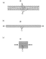
- FIG. 3 is a plan view for explaining the operation of the mesh 15 of the mesh-shaped resin molded product 10 according to the first embodiment, in which (a) shows that no external force is applied to the mesh-shaped resin molded product 10. A normal state is shown, (b) shows a state in which the reticulated resin molded product 10 is stretched, and (c) shows a state in which the reticulated resin molded product 10 is compressed.
- FIGS. 4 and 5 is a front view for explaining the operation of the mesh-shaped resin molded product 10 according to the first embodiment. 4A shows a normal state where no external force is applied to the mesh-shaped resin molded product 10.
- FIG. 4B shows a state in which the reticulated resin molded product 10 is stretched.
- FIG. 4C shows a state where the mesh-shaped resin molded product 10 is compressed.
- FIG. 5A shows a state in which the mesh-shaped resin molded product 10 is bent.
- FIG. 5B shows a state in which the piping member 16 is inserted into the mesh-shaped resin molded product 10 and the mesh-shaped resin molded product is stretched.
- the conventional reticulated resin molded product described in the background section above has the same purpose as the technology described in Patent Documents 4 and 5, for example, protects the hydraulic piping (rubber hose) mounted in an automobile or the like.
- the stretchability of the mesh-shaped resin molded product has room for improvement in terms of fitting (adhering) so as to follow the object to be protected.
- conventional mesh resin molded products are used to protect hydraulic pipes (rubber hoses) mounted in automobiles, etc.
- the conventional reticulated resin molded product has room for improvement in terms of temperature durability.
- the conventional reticulated resin molded product is a woven fabric, there is room for improvement in that when the reticulated resin molded product itself is partially cut, fraying is likely to occur at the ends thereof. Had.
- the mesh-shaped resin molded product 10 according to the present embodiment is used for enclosing and protecting a hollow pipe member provided in a vehicle or a small ship.
- the mesh-shaped resin molded product 10 according to the present embodiment is a member for protecting a hollow pipe provided in a vehicle or a small ship.
- the vehicle described above may have two wheels, three wheels, or four or more wheels as long as it has an internal combustion engine.
- Specific examples of the vehicle include vehicles stipulated in the Road Traffic Law, that is, various vehicles having an internal combustion engine, vehicles such as electric vehicles, fuel cell vehicles, and hybrid vehicles, bicycles with motors, light vehicles and In addition to trolley buses, construction vehicles, agricultural vehicles, industrial vehicles and the like are listed.
- the said small ship refers to the ship of gross tonnage less than 20 tons.
- a pleasure boat, a motor boat, a hovercraft, a yacht with an engine, a water motorcycle (marine jet), etc. are mentioned.
- the mesh-shaped resin molded product 10 which concerns on this embodiment in order to include and protect the hollow piping member with which the motor vehicle which has an internal combustion engine is equipped from a viewpoint of handleability.
- the reticulated resin molded product 10 is placed under a high temperature condition when used, it is necessary to use a resin material excellent in terms of temperature durability (heat resistance), that is, a heat resistant resin material.
- the mesh-shaped resin molded product 10 When the mesh-shaped resin molded product 10 is used for enclosing and protecting a hollow pipe member provided in an automobile having an internal combustion engine, the mesh-shaped resin molded product 10 has heat resistance, flame resistance, Various characteristics such as fuel properties and weather resistance are also required. And in order to form the mesh-shaped resin molded product 10 which satisfy
- the hollow pipe member provided in the vehicle include a fuel supply pipe, a fuel return pipe, a hydraulic pipe, a brake tube, a fuel tube, a power steering tube, and a function different from the vehicle operating system (for example, an air conditioner). And the like.
- the hollow pipe member according to the present embodiment is a member that is provided in a vehicle or a small ship and that has a hollow space for passing a fluid such as liquid or gas.
- the material forming the hollow pipe member according to the present embodiment may be a material formed of a rubber material, a resin material, or a metal material, or may be a laminate or a connection body thereof.
- the mesh-shaped resin molded product 10 includes a plurality of first resin linear portions 11 extending in parallel with each other and extending in a direction intersecting with each other and in parallel with each first resin linear portion 11. And a plurality of second resin linear portions 12 existing. Each 1st resin linear part 11 and each 2nd resin linear part 12 are mutually joined in the junction part 13 located in the mutual crossing part 14. As shown in FIG.
- the cross-sectional shape of the first resin linear portion 11 (the cross-sectional shape orthogonal to the axis 11a of the first resin linear portion 11) is not particularly limited, but is, for example, an oval such as a circle, an ellipse, or an oval. The shape is preferred.
- the cross-sectional shape of the second resin linear portion 12 is the same.
- the net-like resin molded product 10 may be a tube or a sheet. As shown in FIGS. 1A and 1B, in the present embodiment, the following description will be given on the assumption that the reticulated resin molded product 10 is a tube-shaped product, that is, a reticulated resin tube.
- each of the plurality of first resin linear parts 11 is wound in a coaxial spiral shape.
- each of the plurality of second resin linear portions 12 is coaxial with each other and spirals in the opposite direction to the plurality of first resin linear portions 11, and on the outer peripheral side of the plurality of first resin linear portions 11. It is wound.
- the junction part 13 located in the crossing part 14 of each 1st resin linear part 11 and each 2nd resin linear part 12, each 1st The resin linear part 11 and each 2nd resin linear part 12 are mutually joined.
- the cross-sectional shape of the mesh-like resin tube that is, the opening shape when the mesh-like resin tube is viewed in the axial direction, is an oval shape such as a circle, an ellipse, or an oval.
- shaft of both the said 1st resin linear part 11 and the said 2nd resin linear part 12 A direction that passes through the centers 11a and 12a (FIGS. 1C and 2) and is orthogonal to both the axes 11a and 12A is an orthogonal projection direction P (FIGS. 1B and 2). That is, the orthogonal projection direction P is a direction orthogonal to the paper surface of FIG.
- the first resin linear portion 11 and the second resin linear portion 12 are viewed in the orthographic projection direction P, the first resin linear portion 11 and the second resin linear portion 12 overlap.
- the second area, which is the area of the joint portion 13 between the first resin linear portion 11 and the second resin linear portion, is smaller than the first area which is the area (see FIG. 1C).
- the mobility of the joining part 13 is obtained, and the first resin linear part 11 and the second resin linear part 12 can relatively change the angle with the joining part 13 as a fulcrum. Therefore, the mesh-shaped resin molded product 10 can be easily expanded and contracted. Moreover, according to the mesh-shaped resin molded product 10 which concerns on this embodiment, by employ
- the mesh-shaped resin molded product 10 may not have sufficient stretchability in the stage immediately after molding (primary processed product), and in that case, a secondary that improves the mobility of the joint portion 13.
- a reticulated resin molded article 10 having good stretchability is obtained.
- the mesh-shaped resin molded product 10 is configured such that the bonding state between each first resin linear portion 11 and each second resin linear portion 12 is the specific bonding structure described above, and the first resin The area of the overlap between the linear portion 11 and the second resin linear portion 12 is a configuration that satisfies the specific condition described above.
- the hollow pipe member can be enclosed and protected so that the outer surface of the hollow piping member and the mesh-shaped resin molded product 10 are in contact with each other without a gap. Thereby, it is possible to prevent the occurrence of inconveniences such as the displacement of the mesh-shaped resin molded product 10 during use and the hollow pipe member being partially exposed.
- the first resin linear portion 11 and the second resin linear portion 12 are mainly bent and deformed (first The first resin linear portion 11 and the second resin linear portion 12 are not so deformed that the axial direction of the resin linear portion 11 and the second resin linear portion 12 is bent, but the torsional deformation of the joint portion 13 occurs. It preferably has a certain degree of bending rigidity.
- the bending rigidity of the first resin linear part 11 and the second resin linear part 12 sets the thickness (outer diameter), material, molding conditions, etc. of the first resin linear part 11 and the second resin linear part 12. Can be adjusted.
- the second area is preferably 3/4 or less of the first area, and more preferably 2/3 or less of the first area. By doing in this way, sufficient mobility of junction part 13 is realizable.
- the second area is preferably 1/20 or more of the first area, and more preferably 1/10 or more. By doing in this way, sufficient joint strength of junction part 13 is obtained.
- the first resin linear part 11 and the second resin linear part 12 joined to each other are mutually connected with the joint part 13 as a fulcrum (fulcrum X1, X2, etc. shown in FIG. 3).
- the X-link mechanism that can swing is configured.
- the swing axis of the X link mechanism extends, for example, in the orthogonal projection direction P described above.
- the orthographic projection direction P is a direction orthogonal to the paper surface of FIG.
- the mesh-shaped resin molded product 10 can be expanded-contracted in the axial direction. It has become. Further, the reticulated resin molded product 10 can be bent. When the mesh-shaped resin molded product 10 expands and contracts or bends in the axial direction, the first resin linear portion 11 and the second resin linear portion 12 that are bonded to each other are bonded to each other. Using the portion 13 as a fulcrum (fulcrum X1, X2, etc. shown in FIG. 3), the angle changes (oscillates) with each other.
- a pair of first resin linear portions 11 adjacent to each other and a pair of second resin linear portions 12 adjacent to each other serve as a fulcrum (the fulcrum shown in FIG. 3).
- X1, X2, etc.) the mesh 15 formed by the pair of first resin linear portions 11 adjacent to each other and the pair of second resin linear portions 12 adjacent to each other is parallelogram-shaped. (For example, a rhombus shape). Accordingly, the length from the fulcrum X1 to the fulcrum X2 shown in FIG. 3 is maintained substantially constant between the states of FIGS. 3 (a), (b), and (c). That is, the lengths L1 (FIG. 3 (a)), L2 (FIG. 3 (b)), and L3 (FIG. 3 (c)) are equal to each other.
- the shape of the parallelogram includes not only an accurate parallelogram but also a shape that can be regarded as a substantially parallelogram.
- the mesh-shaped resin molded product 10 is a mesh-shaped resin tube as in the present embodiment
- the mesh 15 is formed in a curved shape instead of a planar shape.
- the mesh 15 having a parallelogram shape means that the shape of the mesh 15 when the mesh 15 is viewed in a direction passing through the center of the mesh 15 in a direction orthogonal to the axis of the mesh resin tube. Means a parallelogram shape.
- the mesh-shaped resin tube when the mesh-shaped resin tube is stretched in the axial direction, the mesh-shaped resin tube is reduced in diameter. That is, in the state of FIG. 4B, the diameter of the mesh-like resin tube is smaller than that in the normal state shown in FIG.
- the mesh-shaped resin tube when the mesh-shaped resin tube is compressed (compressed) in the axial direction, the mesh-shaped resin tube expands in diameter. That is, in the state of FIG. 4C, the diameter of the mesh-like resin tube is larger than that in the normal state shown in FIG.
- the mesh-like resin tube is stretched in the axial direction until the adjacent second resin linear portions 12 are in contact with each other.
- the mesh-like resin tube can be stretched in the axial direction until the first resin linear portions 11 adjacent to each other come into contact with each other.
- the mesh-like resin tube is compressed in the axial direction until the second resin linear portions 12 adjacent to each other contact each other. It is possible to do.
- the mesh-like resin tube can be compressed in the axial direction until the first resin linear portions 11 adjacent to each other come into contact with each other.
- the mesh-like resin tube can be bent smoothly in the direction in which the axial direction is bent.
- the mesh-like resin tube can be locally expanded and contracted in the axial direction. For this reason, for example, after inserting the piping member 16 into the mesh-shaped resin tube in a state where the diameter of the mesh-shaped resin tube is expanded, the both ends of the mesh-shaped resin tube are pulled to stretch the mesh-shaped resin tube, As shown in FIGS. 5B and 5C, the diameter of the mesh-shaped resin tube can be reduced so that the inner periphery of the mesh-shaped resin tube fits (adheres to) the piping member 16. Thereby, the piping member 16 can be favorably held by the mesh-like resin tube.
- the material constituting the reticulated resin molded article 10 preferably includes a thermoplastic resin, and the thermoplastic resin includes at least one resin selected from the group consisting of polyethylene, polypropylene, nylon, and polyethylene terephthalate. More preferably, it is included.
- an olefin resin material is preferably used.
- a resin material containing block polypropylene is preferable from the viewpoint of improving the balance between stretchability and flexibility of the mesh-shaped resin molded product 10.
- the mesh-shaped resin molded product 10 is made of an olefin-based resin material, it is possible to easily realize good stretchability and flexibility of the mesh-shaped resin molded product 10.
- the olefin resin material include polyethylene and polypropylene.
- the mesh-shaped resin molded product 10 is comprised with the resin material containing a pigment from a viewpoint of making the elasticity favorable.
- a pigment may be an organic pigment or an inorganic pigment.
- the resin material containing carbon black as said pigment.
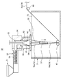
- FIG. 6 is a front cross-sectional view showing an example of a manufacturing apparatus 50 used in the method for manufacturing a reticulated resin molded product according to the first embodiment.
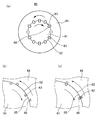
- FIG. 7 is a view showing the structure of the die 60 of the manufacturing apparatus 50 used in the method for manufacturing a reticulated resin molded product according to the first embodiment, in which (a) is a plan sectional view, (b) and ( c) is a partially enlarged plan sectional view.
- Each drawing in FIG. 7 is a cross-sectional plan view seen from above (the connecting portion 54 side).
- FIG. 7 is a cross-sectional plan view seen from above (the connecting portion 54 side).
- FIG. 8 shows the movability of the joint portion 13 between the plurality of first resin linear portions 11 and the plurality of second resin linear portions 12 in the steps of the method for manufacturing the mesh-shaped resin molded product according to the first embodiment. It is a figure for demonstrating an example of the process of improving.
- FIG. 9A shows a joint portion 13 between a plurality of first resin linear portions 11 and a plurality of second resin linear portions 12 in the steps of the method for manufacturing a mesh-shaped resin molded product according to the first embodiment.
- FIG. 9B is a perspective view showing an example of the shape of the rollers 75 and 76 (rollers 78 and 79).
- a plurality of first resin linear portions 11 extending in parallel with each other, and a direction intersecting with each other in parallel with each other.
- a plurality of second resin linear portions 12 extending to the first resin linear portions 11 and the second resin linear portions 12 at the junctions 13 located at the intersections 14 of each other.
- a mesh-shaped resin molded product 10 bonded to each other is manufactured.
- shaft of both the said 1st resin linear part 11 and the said 2nd resin linear part 12 An orthogonal projection direction P is defined as a direction passing through the centers 11a and 12a and orthogonal to both the axes 11a and 12a.
- the second area which is the area of the joint portion 13 between the first resin linear portion 11 and the second resin linear portion 12, is smaller than the first area that is the overlapping area with the portion 12. It has the process of shape
- the mesh structure 70 may be the mesh-shaped resin molded product 10 (the mesh-shaped resin molded product 10 is manufactured).
- the mesh structure 70 may be the mesh-shaped resin molded product 10 itself.
- the network structure 70 is a primary processed product obtained by resin molding, and the network resin molded product 10 is manufactured by performing secondary processing on the network structure 70. The following explanation will be given.
- the step of forming the mesh structure 70 is performed, for example, by extruding a resin material through the die 60 using the manufacturing apparatus 50 shown in FIG.
- a resin material those described above are used. That is, for example, an olefin resin material is preferably used.
- a resin material containing carbon black is preferably used.
- the manufacturing apparatus 50 includes a hopper 51 into which a resin material is charged, an extruder 52 that has a screw 53 inside and melts and extrudes the resin material, and the resin material is fed into the network structure 70.
- a die 60 that is molded into a shape and discharged; a connecting portion 54 that connects the extruder 52 and the die 60 to each other; a sizing 57 that adjusts the inner diameter of the network structure 70 discharged from the die 60; It has.
- the manufacturing apparatus 50 further includes a cooling water tank 71 that stores the cooling water 72 and cools the molded network structure 70, a take-off roller 67 that takes up the molded network structure 70, and a winding device (not shown).
- a roller 68 disposed between the take-up roller 67 and engaging with the mesh structure 70.
- the resin material put into the hopper 51 is heated and melted by the extruder 52 and is pushed out to the connecting portion 54 side by the screw 53.
- a flow path is formed in which the internal space of the extruder 52 and the internal space of the die 60 are communicated with each other, and the molten resin material (molten resin) passes through the flow path. 60.
- the die 60 has a double structure having a first portion 61 and a second portion 64.
- the first portion 61 has a conical outer peripheral surface 62.
- the first portion 61 is arranged in such a posture that the center axis of the cone is along the vertical direction, and the bottom side of the cone is down and the top side is up.
- a plurality of first grooves 63 (see FIG. 7) extending in parallel with each other are formed on the outer peripheral surface 62 along the generatrix of the outer peripheral surface 62 (conical bus forming the outer peripheral surface 62). .
- a plurality of first grooves 63 are formed at predetermined intervals (for example, constant intervals) in the circumferential direction of the outer peripheral surface 62 at the lower end portion of the outer peripheral surface 62 of the first portion 61. Yes.
- the second portion 64 has a conical inner peripheral surface 65.
- the second portion 64 is arranged such that its inner peripheral surface 65 is coaxial with the outer peripheral surface 62 of the first portion 61, and the conical bottom side is down and the top side is up.
- a plurality of second grooves 66 (see FIG. 7) extending in parallel with each other are formed along the generatrix of the inner peripheral surface 65 (the conical bus forming the inner peripheral surface 65).
- a plurality of second grooves 66 are formed at predetermined intervals (for example, constant intervals) in the circumferential direction of the inner peripheral surface 65 at the lower end portion of the inner peripheral surface 65 of the second portion 64. Has been.
- the first portion 61 is disposed inside the inner peripheral surface 65 of the second portion 64. Therefore, the outer peripheral surface 62 of the first portion 61 and the inner peripheral surface 65 of the second portion 64 face each other. That is, grooves (first groove 63 and second groove 66) that open toward each other are formed on the outer peripheral surface 62 and the inner peripheral surface 65, respectively.
- the outer peripheral surface 62 and the inner peripheral surface 65 are in sliding contact with each other on the discharge side of the resin material from the die 60, that is, on the lower end side of the die 60.
- the outer peripheral surface 62 and the inner peripheral surface 65 are separated from each other. For this reason, the molten resin flowing down from the connecting portion 54 can be smoothly received in the gap between the outer peripheral surface 62 and the inner peripheral surface 65.
- the die 60 is configured so that the first portion 61 and the second portion 64 can be relatively rotated around the axis.
- the first portion 61 is suspended and supported by a rotating shaft 55 that extends upward from the upper end of the first portion 61 coaxially with the first portion 61 (coaxial with the conical shape constituting the outer peripheral surface 62 of the first portion 61). ing.
- the rotation shaft 55 is driven by a first rotation drive mechanism (not shown) and rotates around the axis. Along with this rotation, the first portion 61 to which the rotation shaft 55 is fixed also rotates around the axis.
- the rotating shaft 55 is pivotally supported by a shaft support hole formed in the upper portion of the connecting portion 54.
- a donut-shaped wheel 56 is fixed to the lower end portion of the second portion 64 coaxially with the second portion 64 (coaxial with the conical shape constituting the inner peripheral surface 65 of the second portion 64).
- the wheel 56 is driven by a second rotation drive mechanism (not shown) and rotates around the axis. With this rotation, the second portion 64 rotates around the axis.
- the upper end portion of the second portion 64 is held at the lower portion of the connecting portion 54 so as to be rotatable around the axis of the second portion 64 relative to the connecting portion 54.
- the rotation direction or rotation speed (angular velocity) between the first portion 61 and the second portion 64 is set so that the first portion 61 and the second portion 64 rotate relatively around the axis. . More specifically, for example, the first portion 61 and the second portion 64 are rotated in opposite directions. In this case, the first part 61 and the second part 64 may be rotated at the same rotational speed, but the rotational speeds of the first part 61 and the second part 64 may be different from each other. For example, the first portion 61 and the second portion 64 are rotated at a constant rotation speed, respectively. By doing in this way, the spiral winding pitch of each of the first resin linear portion 11 and the second resin linear portion 12 is made constant in the longitudinal direction of the mesh structure 70 and thus the mesh-shaped resin molded product 10. can do.
- the sizing 57 is formed in a columnar shape or a cylindrical shape, and is disposed below the wheel 56 coaxially with the first portion 61 and the second portion 64 of the die 60.
- the sizing 57 is supported by being suspended from the lower surface of the second portion 64 via a sizing support portion 58 having a bar shape or the like.
- the upper end of the sizing support portion 58 is fixed to the lower surface of the second portion 64 through the opening of the wheel 56.
- the sizing 57 is rotatable around the axis with respect to the first portion 61, for example. For this reason, transmission of rotational force from the first portion 61 to the sizing 57 is suppressed. Accordingly, the sizing 57 is prevented from rotating inside the mesh structure 70 discharged from the die 60, and the sizing 57 is idle with respect to the first portion 61.
- the inner diameters of the mesh structure 70 and the mesh-shaped resin molded product 10 are molded to a size corresponding to the outer diameter of the sizing 57.
- the outer diameter of the sizing 57 is set to be equal to or less than the diameter of the discharge portion of the die 60, that is, the diameter of the lower end of the outer peripheral surface 62 of the first portion 61 and the inner peripheral surface 65 of the second portion 64. That is, the step of forming the mesh structure 70 is performed in a state where the sizing 57 having a smaller diameter than the die discharge portion is disposed on the downstream side of the die 60. That is, the mesh structure 70 (mesh resin molded product 10) is molded by so-called deflation molding. Thereby, the mesh structure 70 and the mesh-shaped resin molded product 10 can be molded so that the inner diameters of the mesh structure 70 and the mesh-shaped resin molded product 10 are equal to or less than the diameter of the discharge portion of the die 60.
- the take-up roller 67 is composed of a pair of rotating rollers, and is disposed further below the sizing 57.
- the take-up roller 67 takes up the mesh structure 70 (mesh structure 70 b) formed by the sizing 57.
- the cooling water 72 is stored up to the same water level as the height of the lower surface of the wheel 56.
- the sizing 57 and the take-up roller 67 are submerged in the cooling water 72.
- the roller 68 is disposed downstream of the take-up roller 67.
- the roller 68 is disposed outside the cooling water tank 71 and engages with the mesh structure 70 (mesh structure 70 c) after being cooled by the cooling water 72.
- the manufacturing apparatus 50 includes, for example, a mobility improving mechanism shown in FIG. 8 or FIG.
- the mobility improving mechanism is for performing secondary processing for improving the mobility of the joint portion 13 between the plurality of first resin linear portions 11 and the plurality of second resin linear portions 12.
- the mobility improving mechanism is disposed on the downstream side of the roller 68 (FIG. 6) and on the upstream side of a winding device (not shown).
- the angle formed by the first resin linear portion 11 and the second resin linear portion 12 that are joined to each other at the joint portion 13 with respect to the mesh structure 70c that is a primary processed product is changed.
- the mesh structure 70c is deformed by applying a force in the direction of the movement. More specifically, a force is applied to the mesh structure 70c in the direction in which the angle formed by the first resin linear portion 11 and the second resin linear portion 12 changes with the orthographic projection direction P as a rotation axis. In addition, the mesh structure 70c is deformed.
- the joint portion 13 becomes weak (the torsional rigidity of the joint portion 13 decreases), and as a result, the mobility of the joint portion 13 is improved.
- the joint portion 13 is weakened without breaking (peeling). More specifically, for example, a deformation in which elastic deformation and plastic deformation are mixed occurs in the joint portion 13, whereby the joint portion 13 remains connected (without breaking the joint portion 13). Is partially stretched (plastically deformed), the torsional rigidity of the joint portion 13 is reduced. Or the junction part 13 becomes weak by partially fracture
- the method for producing a mesh-shaped resin molded article applies a force to the joint portion between the first resin linear portion 11 and the second resin linear portion 12 by deforming the primary processed product, and the joint portion. Is partially broken (peeled), and a part (for example, the central portion) of the joint portion is left as the final joint portion 13.
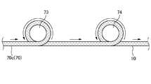
- the mobility improving mechanism shown in FIG. 8 includes a stretching roller 73 and a stretching roller 74 disposed on the downstream side of the stretching roller 73.
- the stretching roller 73 is applied with a rotational driving force by a first roller driving mechanism (not shown), rotates at a first rotational speed while being engaged with the mesh structure 70c, and has a mesh structure at a first transport speed.
- the body 70c is conveyed downstream.
- the stretching roller 74 is given a rotational driving force by a second roller driving mechanism (not shown), and rotates at a second rotational speed higher than the first rotational speed in a state of being engaged with the mesh structure 70c.
- the mesh structure 70c is transported downstream at a second transport speed that is higher than the first transport speed.
- the mesh structure 70c is stretched (that is, deformed) between the stretching roller 73 and the stretching roller 74 in the axial direction of the mesh structure 70c.
- the mobility of the junction part 13 of the some 1st resin linear part 11 of the mesh structure 70c and the some 2nd resin linear part 12 improves. That is, when the mobility improving mechanism of FIG. 8 is used, a plurality of first resin linear portions 11 and a plurality of second resin linear portions are formed by stretching a mesh-like resin tube as the mesh structure 70c in the axial direction. The process of improving the movability of the joint part 13 with 12 is performed.
- the mesh structure 70 c is wound around the stretch roller 73 (for example, a plurality of turns) so that the mesh structure 70 c can be sufficiently gripped by the stretch roller 73. It is preferable to transport the mesh structure 70c. By doing in this way, the slip of the mesh structure 70c with respect to the stretching roller 73 can be suppressed. It is also preferable that the surface of the stretching roller 73 is an uneven surface (rough surface) so that the network structure 70 c can be sufficiently gripped by the stretching roller 73.
- the network structure 70c is wound around the stretching roller 74 (for example, a plurality of windings) so that the network structure 70c can be sufficiently gripped by the stretching roller 74. It is preferable to transport the mesh structure 70 c by the roller 74. By doing in this way, the slip of the mesh structure 70c with respect to the stretching roller 74 can be suppressed. It is also preferable that the surface of the stretching roller 74 is a rough surface (rough surface) so that the network structure 70 c can be sufficiently gripped by the stretching roller 74.
- the mobility improving mechanism shown in FIG. 9 includes a diameter expanding member 77 that expands the mesh structure 70 c, a pair of rollers 75, 76 disposed on the upstream side of the diameter expanding member 77, and the diameter expanding member 77. And a pair of rollers 78 and 79 disposed on the downstream side (FIG. 9A).
- the diameter-enlarging member 77 is a rugby ball-shaped (or egg-shaped) member having a shorter diameter than the inner diameter of the mesh structure 70c, and the longer diameter is arranged along the conveying direction of the mesh structure 70c.
- the distance from the pair of rollers 75 and 76 to the pair of rollers 78 and 79 is set to be slightly longer than the long diameter of the diameter-expanding member 77.
- the pair of rollers 75 and 76 conveys the mesh structure 70c to the downstream side with the mesh structure 70c sandwiched therebetween. As a result, the mesh structure 70 c is extrapolated around the diameter expanding member 77.
- the pair of rollers 75 and 76 is given a rotational driving force by a roller driving mechanism (not shown).
- the pair of rollers 78 and 79 convey the mesh structure 70c to the downstream side in a state where the mesh structure 70c is sandwiched between them.
- the pair of rollers 78 and 79 may or may not be given a driving force.
- the diameter-expanding member 77 is surrounded by the mesh structure 70c between the pair of rollers 75 and 76 and the pair of rollers 78 and 79, and is held by the mesh structure 70c. Further, the pair of rollers 78 and 79 on the downstream side restricts the diameter expanding member 77 from being pushed downstream.
- an arc-shaped groove 700 is formed in the center in the width direction of each roller 75, 76, 78, 79. ing.
- the mesh structure 70c can be held with an appropriate clamping force in the gap between the grooves 700 of the pair of rollers 75 and 76, and similarly, with an appropriate clamping force in the gap between the grooves 700 of the pair of rollers 78 and 79.
- the mesh structure 70c can be held.
- the downstream end of the diameter-expanding member 77 can be suitably positioned in the gap between the grooves 700 of the pair of rollers 78 and 79 on the downstream side.
- the mesh structure 70 c When the mobility of the joint portion 13 is improved by the mobility improvement mechanism shown in FIG. 9, the mesh structure 70 c is conveyed downstream while the mesh structure 70 c is extrapolated with respect to the diameter expanding member 77. Thereby, when the mesh structure 70c passes around the diameter-expanding member 77, the mesh structure 70c is expanded in diameter and compressed in the axial direction. For this reason, the mobility of the junction part 13 of the some 1st resin linear part 11 and the some 2nd resin linear part 12 of the mesh structure 70c improves. That is, when the mobility improving mechanism of FIG. 9 is used, the plurality of first resin linear portions 11 and the plurality of second resin linear shapes are formed by pressing and contracting the mesh resin tube as the mesh structure 70c in the axial direction. The process of improving the mobility of the joint part 13 with the part 12 will be performed.
- the strength of the force sandwiching the mesh structure 70c between the pair of rollers 75 and 76 and between the pair of rollers 78 and 79 is the first resin linear portion 11 of the mesh structure 70c. And it is preferable to restrict
- the surfaces of the rollers 75, 76, 78, and 79 are rough surfaces so that the mesh structure 70 c can be sufficiently gripped by the pair of rollers 75, 76 and the pair of rollers 78, 79. It is also preferable.
- the molten resin is extruded by the extruder 52, the molten resin (that is, the reticulated structure 70) is discharged from the die 60, and the reticulated roller 67 takes off the reticulated structure 70. Then, the operation of improving the mobility of the joint portion 13 of the mesh structure 70c by the mobility improving mechanism and the winding of the mesh-shaped resin molded product 10 by a winding device (not shown) are continuously performed in parallel.
- the resin material put into the hopper 51 is heated and melted by the extruder 52 and supplied to the die 60 through the flow path of the connecting portion 54.
- first portion 61 and the second portion 64 of the die 60 are relatively rotated around the axis.
- the first resin linear portion 11 and the second portion The resin linear portion 12 is discharged from the discharge port of the die 60 while being separated from each other. That is, the 1st resin linear part 11 is shape
- the first resin linear portion 11 is separated by the resin material discharged from between the second groove 66 and the portion of the outer peripheral surface 62 of the first portion 61 other than the portion where the first groove 63 is formed.
- the second resin linear portion 12 is molded.
- the first intersecting each other at the timing when the first groove 63 of the first portion 61 and the second groove 66 of the second portion 64 face each other and communicate with each other, the first intersecting each other.
- the resin linear portion 11 and the second resin linear portion 12 are discharged from the discharge port of the die 60 in a state where they are bonded to each other via the bonding portion 13. That is, the first resin linear portion 11 and the second resin linear portion 12 that are integrated with each other are discharged from the opening formed by the combination of the first groove 63 and the second groove 66.
- the joining part 13 is a fused part in which the first resin linear part 11 and the second resin linear part 12 are fused to each other.
- mesh structure 70 (mesh structure 70a) having the same shape as that of the mesh-shaped resin molded product 10 shown in FIG.
- the first portion 61 and the second portion 64 are rotated relative to each other around the axis, and the gaps between the plurality of first grooves 63 and the second grooves 66, and A resin material is extruded through the gaps between the plurality of second grooves 66 and the first portion 61.
- each of the plurality of first resin linear portions 11 is wound in a coaxial spiral shape
- each of the plurality of second resin linear portions 12 is coaxial with each other and the plurality of first resins.
- a mesh-shaped resin tube formed by being wound around the outer peripheral side of the plurality of first resin linear portions 11 in a spiral shape opposite to the linear portion 11 is formed.
- the mesh structure 70 a discharged from the die 60 is submerged in the cooling water 72 in the cooling water tank 71 and is taken up by the take-up roller 67 after being adjusted by the sizing 57 while being cooled by the cooling water 72.
- the outer diameter of the sizing 57 is equal to or smaller than the diameter of the discharge portion of the die 60.
- the 1st resin linear part 11 located in the inner peripheral side among the 1st resin linear part 11 and the 2nd resin linear part 12 is with respect to the 2nd resin linear part 12 located in the outer peripheral side. It is suppressed that it is pressed strongly.
- expansion of the area of the joint portion 13 between the first resin linear portion 11 and the second resin linear portion 12 is moderately suppressed.
- the second area is larger than the first area. Becomes smaller.
- the mesh structure 70 b after being taken up by the take-up roller 67 is conveyed toward the roller 68 and goes out of the cooling water tank 71 in the process.
- the mesh structure 70 (mesh structure 70c) after being engaged with the roller 68 has a mobility improving mechanism shown in FIG. 8 or a mobility shown in FIG. 9 until it is taken up by a winding device (not shown). A step of improving the mobility of each joint portion 13 is performed by the improvement mechanism.
- the mesh structure 70 that has undergone this process becomes the mesh-shaped resin molded product 10.
- the step of forming the mesh structure 70, the step of cooling the mesh structure 70, and the step of improving the mobility of the joint portion 13 are performed in this order.
- the mesh-shaped resin molded product 10 that is the mesh structure 70 that has undergone the step of improving the mobility of each joint portion 13 does not necessarily have to be wound around a winding device. It may be cut into dimensions.
- the first resin linear portion 11 and the second resin linear portion 12 joined to each other are viewed in the orthographic projection direction P, the first More than the 1st area which is the overlap area of the resin linear part 11 and the said 2nd resin linear part 12, of the junction part 13 of the said 1st resin linear part 11 and the said 2nd resin linear part 12
- the second area, which is the area is small.
- the network structure 70 which is a primary processed product does not have sufficient stretchability
- a secondary process for improving the mobility of the joint portion 13 with respect to the mesh structure 70 good stretchability can be obtained.
- It can be set as the reticulated resin molded product 10 having. That is, when the reticulated resin molded product 10 is a reticulated resin tube, a joining portion is obtained by performing a step of stretching the reticulated resin tube in the axial direction or a step of compressing the reticulated resin tube in the axial direction. The mobility of 13 can be improved.
- the step of stretching the mesh-shaped resin tube in the axial direction and the step of compressing the mesh-shaped resin tube in the axial direction may be performed alternatively, or both may be performed.
- the favorable mobility of the junction part 13 can be expressed by repeating both processes alternately.
- the secondary processing for improving the mobility of the joint portion 13 may be performed on the entire mesh structure 70 or may be selectively performed on a part of the mesh structure 70. According to the former, the stretchability of the mesh-shaped resin molded product 10 can be made uniform throughout the mesh-shaped resin molded product 10, while according to the latter, the mesh-shaped resin molded product 10 is selectively used in a part of the mesh-shaped resin molded product 10. Can exhibit good stretchability.
- the network-shaped resin molded product 10 that is a network-shaped resin tube may be stretched or pressed by hand to exhibit good stretchability of the network-shaped resin molded product 10.
- a user who uses the mesh-shaped resin molded product 10 has good stretchability only in a necessary portion by selectively performing secondary processing on a portion of the mesh structure 70 immediately before use. May be allowed.
- the mesh-like resin molded product 10 is a mesh-like resin tube as in this embodiment
- the mesh-like resin molded product 10 can be expanded and contracted in the axial direction with a light force.
- the mesh-shaped resin molded product 10 that is a mesh-shaped resin tube has a reduced diameter when stretched in the axial direction and expands when compressed in the axial direction.
- the mesh-shaped resin molded product 10 which is a mesh-shaped resin tube is compressed from the periphery in the radial direction (for example, when gripped by hand), the mesh-shaped resin molded product 10 is reduced in diameter.
- the mesh-shaped resin molded product 10 also has good flexibility, the occurrence of kinks during bending is also suppressed.
- the first resin linear portion 11 and the second resin linear portion 12 joined to each other constitute an X-link mechanism that can swing relative to each other using the joint portion 13 as a fulcrum. ing. Therefore, when the mesh-shaped resin molded product 10 expands and contracts or bends in the axial direction, the first resin linear portion 11 and the second resin linear portion 12 that are bonded to each other are connected to each other. The angle changes with respect to 13 as a fulcrum. At that time, for example, the mesh 15 is maintained in a parallelogram shape. In other words, since the mesh-shaped resin molded product 10 can be expanded and contracted without substantially bending (bending) each first resin linear portion 11 and each second resin linear portion 12, the mesh-shaped resin molded product 10. A large stretch ratio can be obtained.
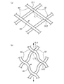
- FIG. 15 is a figure for demonstrating operation
- (a) is the normal state in which the external force is not provided to the mesh-shaped resin molded product which concerns on a comparison form
- (B) shows the state where the mesh-shaped resin molded product according to the comparative embodiment is stretched.
- the mesh-shaped resin molded product according to the comparative embodiment extends in a direction intersecting with each of the first resin linear portions 81 in parallel with each other and the plurality of first resin linear portions 81 extending in parallel with each other.
- Each 1st resin linear part 81 and each 2nd resin linear part 82 are mutually joined in the junction part located in a mutual intersection.
- the mesh-shaped resin molded product according to the comparative embodiment is the same as the mesh-shaped resin molded product 10 according to the present embodiment.
- the first area and the second area are equal to each other.
- the mesh-shaped resin molded product according to the comparative form is manufactured by, for example, so-called inflation molding performed using sizing having an outer diameter larger than the diameter of the discharge portion of the die. For this reason, since the 1st resin linear part 81 is strongly pressed with respect to the 2nd resin linear part 82 when a mesh-shaped resin molded product passes sizing, a 1st area and a 2nd area are mutually equal. It becomes an area. Therefore, the mobility of the joint between the first resin linear part 81 and the second resin linear part 82 is poor, and the first resin linear part 81 and the second resin linear part 82 are substantially at the joint. And are fixed to each other. When the reticulated resin molded product is stretched in the direction of the arrow shown in FIG.
- the area of the mesh 85 shown in FIG. 15B is smaller than the area of the mesh 85 shown in FIG.
- the mesh-shaped resin molded product according to the comparative example expands and contracts in the direction of the arrow shown in FIG. 15B, the four sides forming the mesh are bent (FIG. 15B), and the original straight line
- the mesh-shaped resin molded product is deformed between the state (FIG. 15A) returned to the state of the shape. For this reason, the distance between the fulcrum X11 and the fulcrum X12 expands and contracts with expansion and contraction of the mesh-shaped resin molded product.
- the mesh-shaped resin molded product according to the comparative embodiment can extend to some extent in the direction of the arrow in FIG. 15B, but extends in the direction orthogonal to the arrow in FIG. 15B. It is difficult (it hardly grows).
- FIG. 10 is a plan view of the mesh-shaped resin molded product 10 according to the second embodiment, in which (a) shows a normal state where no external force is applied to the mesh-shaped resin molded product 10, and (b) The reticulated resin molded product 10 is shown stretched in the first direction, and (c) shows the reticulated resin molded product 10 stretched in a second direction orthogonal to the first direction. .
- the reticulated resin molded product 10 is a reticulated resin tube
- the reticulated resin molded product 10 is a sheet.
- the mesh-shaped resin molded product 10 is opened and opened, thereby forming a sheet-shaped mesh-shaped resin molded product.
- Product 10 is obtained.
- the joint portions 13 between the first resin linear portions 11 and the second resin linear portions 12 are the same as those in the first embodiment in the present embodiment.
- the stretchability of the mesh-shaped resin molded product 10 is the same as that of the first embodiment.
- the reticulated resin molded product 10 can be greatly expanded and contracted in the first direction, and can also be expanded and contracted greatly in the second direction orthogonal to the first direction.
- Example 1 As the mesh-shaped resin molded product 10 according to Example 1, the mesh-shaped resin molded product 10 according to the first embodiment was manufactured. Polypropylene containing carbon black is used as the resin material, and each of the elliptical first resin linear portion 11 and second resin linear portion 12 has a major axis (width direction) of 1.4 mm and a minor axis (thickness direction) of 1.
- the number of the first resin linear portions 11 is 12, the number of the second resin linear portions 12 is 12, and the pitch between the intersections in the network structure 70c that is a primary processed product (the distance between adjacent intersections) That is, the distance between the centers of adjacent joints 13) is 7.0 mm in the axial direction of the mesh-like resin tube, 3.0 mm in the width direction of the mesh-like resin tube, and the mesh structure 70c that is a primary processed product
- the inner diameter of the mesh-shaped resin tube is 9.0 mm, and the winding pitch of the first resin linear portion 11 and the second resin linear portion 12 (the first resin linear portion 11 and the second resin linear portion 12 make one round).
- the length of the structural network 70c in the axial direction has a molding condition such that 84.0Mm.
- the mobility of the junction part 13 was improved by expanding and contracting the network structure 70c after shaping
- the axes of both the first resin linear part 11 and the second resin linear part 12 When the first resin linear portion 11 and the second resin linear portion 12 are viewed in the orthographic projection direction, the direction passing through the center and orthogonal to both of the axes is the orthographic projection direction.
- the overlapping area A (first area) of the first resin linear part 11 and the second resin linear part 12 and the area B of the joint part between the first resin linear part 11 and the second resin linear part 12 The ratio of (second area) and the value of B / A were 0.54.
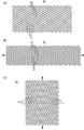
- FIG. 11 is a view (both are micrographs) showing the vicinity of the joint portion 13 of the mesh-shaped resin molded product 10 according to the first embodiment, in which (a) performs a step of improving the mobility of the joint portion 13.
- the previous state (the state of the mesh structure 70c) is shown, and (b) and (c) show the state after the process (the state of the mesh-shaped resin molded product 10).
- FIG. 11B shows a state where the mesh-shaped resin molded product 10 is stretched in the axial direction
- FIG. 11C shows a state where the mesh-shaped resin molded product 10 is compressed in the axial direction.
- FIG. 12 is a diagram for explaining the operation of the mesh-shaped resin molded product 10 according to Example 1, in which (a) shows a normal state where no external force is applied to the mesh-shaped resin molded product 10, b) shows a state in which the reticulated resin molded product 10 is stretched in the axial direction, and (c) shows a state in which the reticulated resin molded product 10 is compressed in the axial direction.
- FIG. 12 it can be seen that the reticulated resin molded article 10 can be expanded and contracted very greatly. In particular, it can be seen that the expansion / contraction ratio between the normal state (FIG. 12A) and the compressed state (FIG. 12C) is very large.
- Example 2 As the mesh-shaped resin molded product 10 according to Example 2, the mesh-shaped resin molded product 10 according to the first embodiment was manufactured. Polypropylene containing carbon black is used as the resin material, and the first resin linear portion 11 and the second resin linear portion 12 each having an elliptical shape have a major axis (width direction) of 0.7 mm and a minor axis (thickness direction) of 0.
- the number of the first resin linear portions 11 is 14, the number of the second resin linear portions 12 is 14, and the pitch between the intersection points in the network structure 70c that is a primary processed product (the distance between adjacent intersection points) In other words, the distance between the centers of adjacent joints 13) is 5.5 mm in the axial direction of the mesh-shaped resin tube, and 5.5 mm in the width direction of the mesh-shaped resin tube.
- the molding conditions were such that the inner diameter of the mesh-like resin tube was 25 mm, and the winding pitch of the first resin linear portion 11 and the second resin linear portion 12 was 77.0 mm.
- the mobility of the junction part 13 was improved by expanding and contracting the network structure 70c after a shaping
- the axes of both the first resin linear part 11 and the second resin linear part 12 When the first resin linear portion 11 and the second resin linear portion 12 are viewed in the orthographic projection direction, the direction passing through the center and orthogonal to both of the axes is the orthographic projection direction.
- the overlapping area A (first area) of the first resin linear part 11 and the second resin linear part 12 and the area B of the joint part between the first resin linear part 11 and the second resin linear part 12 The ratio of (second area) and the value of B / A were 0.38.
- FIG. 13 is a diagram for explaining the operation of the mesh-shaped resin molded product 10 according to the second embodiment, in which (a) shows a normal state where no external force is applied to the mesh-shaped resin molded product 10, b) shows a state in which the reticulated resin molded product 10 is stretched in the axial direction, and (c) shows a state in which the reticulated resin molded product 10 is compressed in the axial direction.
- the mesh-shaped resin molded product 10 can be expanded and contracted further than Example 1.
- the expansion / contraction ratio between the normal state (FIG. 13A) and the compressed state (FIG. 13C) is very large.
- FIG. 14 is a diagram showing the measurement results of the expansion / contraction rate of the mesh-shaped resin molded product 10 according to Example 1 and Example 2.
- Example 1 the length of the reticulated resin molded product 10 at each time of stretching (FIG. 12B), normal time (FIG. 12A), and pressing time (FIG. 12C) (mesh shape).
- the length of the resin tube in the axial direction) was 520 mm, 481 mm, and 130 mm, respectively. That is, the maximum expansion / contraction rate (length at the time of expansion / length at the time of compression) was 4.00.
- Example 2 the length of the reticulated resin molded product 10 at each time of stretching (FIG. 13B), normal time (FIG.
- Example 1 the outer diameter of the reticulated resin molded product 10 at the time of stretching (FIG. 12B), at the time of normal operation (FIG. 12A), and at the time of compression (FIG. 12C) ( The outer diameters of the mesh-like resin tubes were 11 mm, 16.5 mm, and 31.5 mm, respectively. That is, the maximum expansion / contraction ratio (outer diameter at the time of compression / outer diameter at the time of expansion) with respect to the outer diameter was 2.86.
- Example 2 the folding width of the reticulated resin molded product 10 at each time of stretching (FIG. 13B), normal time (FIG. 13A), and pressing time (FIG. 13C) (
- the outer diameter (major diameter of the mesh-like resin tube) was 8 mm, 38 mm, and 52 mm, respectively. That is, the maximum expansion / contraction ratio (folding width at the time of pressing / folding width at the time of stretching) of the folding width was 6.50.
- a reticulated resin tube was produced by inflation molding under the same materials and molding conditions as in Example 1.
- the mesh-like resin tube had a large joint rigidity and did not exhibit stretchability.
Landscapes
- Engineering & Computer Science (AREA)
- Mechanical Engineering (AREA)
- General Engineering & Computer Science (AREA)
- Manufacturing & Machinery (AREA)
- Physics & Mathematics (AREA)
- Thermal Sciences (AREA)
- Rigid Pipes And Flexible Pipes (AREA)
- Extrusion Moulding Of Plastics Or The Like (AREA)
- Protection Of Pipes Against Damage, Friction, And Corrosion (AREA)
Abstract
車両あるいは小型船舶が備える中空配管部材を内包して保護するために用いる網目状樹脂成形品(10)であって、当該網目状樹脂成形品(10)に対して負荷がかかっていない常態である場合に、網目状樹脂成形品(10)は、互いに並列に延在する複数の第1樹脂線状部(11)と、互いに並列に且つ各第1樹脂線状部(11)に対して交差する方向に延在する複数の第2樹脂線状部(12)を有する。各第1樹脂線状部(11)と各第2樹脂線状部(12)とは、互いの交差部に位置する接合部(13)において相互に接合されている。交差部において、当該第1樹脂線状部(11)及び当該第2樹脂線状部(12)の双方の軸心を通り且つ当該双方の軸心に対して直交する方向を正射投影方向Pとする。正射投影方向Pに当該第1樹脂線状部(11)及び当該第2樹脂線状部(12)を見たときに、当該第1樹脂線状部(11)と当該第2樹脂線状部(12)との重なりの面積である第1面積よりも、当該第1樹脂線状部(11)と当該第2樹脂線状部(12)との接合部(13)の面積である第2面積が小さく、複数の第1樹脂線状部(11)と、複数の第2樹脂線状部(12)とが、熱可塑性樹脂を含む材料により形成されている。
Description
本発明は、網目状樹脂成形品に関する。
網目状樹脂チューブのような網目状樹脂成形品、及びその製造方法については、例えば、特許文献1乃至3等に記載されている。
このうち、特許文献1には、屈曲性に優れた構造の網目状樹脂チューブが記載されている。
本発明者等の知見によれば、特許文献1に記載された網目状樹脂成形品を含む従来の網目状樹脂成形品では、伸縮性が十分ではなかった。すなわち、特許文献1に記載された網目状樹脂チューブは、ある程度の屈曲性は有しているかも知れないが、軸方向における伸縮性が十分ではない。
また、従来の網目状樹脂成形品を、特許文献4および5等に記載されている技術と同様の目的、すなわち、自動車等に搭載されている屈曲した油圧配管(ゴムホース)を保護する目的で使用した場合、かかる網目状樹脂成形品の伸縮性は、保護対象に追従するようにフィット(密着)させるという観点において、改善の余地を有していた。また、従来の網目状樹脂成形品について、該網目状樹脂成形品自体を部分的に切断した際に、その端部にほつれが生じやすいという点においても、改善の余地を有していた。
また、従来の網目状樹脂成形品を、特許文献4および5等に記載されている技術と同様の目的、すなわち、自動車等に搭載されている屈曲した油圧配管(ゴムホース)を保護する目的で使用した場合、かかる網目状樹脂成形品の伸縮性は、保護対象に追従するようにフィット(密着)させるという観点において、改善の余地を有していた。また、従来の網目状樹脂成形品について、該網目状樹脂成形品自体を部分的に切断した際に、その端部にほつれが生じやすいという点においても、改善の余地を有していた。
本発明は、
車両あるいは小型船舶が備える中空配管部材を内包して保護するために用いる網目状樹脂成形品であって、
当該網目状樹脂成形品に対して負荷がかかっていない常態である場合に、互いに並列に延在する複数の第1樹脂線状部と、互いに並列に且つ各第1樹脂線状部に対して交差する方向に延在する複数の第2樹脂線状部と、を有し、各第1樹脂線状部と各第2樹脂線状部とが互いの交差部に位置する接合部において相互に接合されており、
互いに接合された前記第1樹脂線状部と前記第2樹脂線状部との交差部において、当該第1樹脂線状部及び当該第2樹脂線状部の双方の軸心を通り且つ当該双方の軸心に対して直交する方向を正射投影方向とすると、当該正射投影方向に当該第1樹脂線状部及び当該第2樹脂線状部を見たときに、当該第1樹脂線状部と当該第2樹脂線状部との重なりの面積である第1面積よりも、当該第1樹脂線状部と当該第2樹脂線状部との接合部の面積である第2面積が小さく、
前記複数の第1樹脂線状部と、前記複数の第2樹脂線状部とが、熱可塑性樹脂を含む材料により形成されている網目状樹脂成形品を提供する。
車両あるいは小型船舶が備える中空配管部材を内包して保護するために用いる網目状樹脂成形品であって、
当該網目状樹脂成形品に対して負荷がかかっていない常態である場合に、互いに並列に延在する複数の第1樹脂線状部と、互いに並列に且つ各第1樹脂線状部に対して交差する方向に延在する複数の第2樹脂線状部と、を有し、各第1樹脂線状部と各第2樹脂線状部とが互いの交差部に位置する接合部において相互に接合されており、
互いに接合された前記第1樹脂線状部と前記第2樹脂線状部との交差部において、当該第1樹脂線状部及び当該第2樹脂線状部の双方の軸心を通り且つ当該双方の軸心に対して直交する方向を正射投影方向とすると、当該正射投影方向に当該第1樹脂線状部及び当該第2樹脂線状部を見たときに、当該第1樹脂線状部と当該第2樹脂線状部との重なりの面積である第1面積よりも、当該第1樹脂線状部と当該第2樹脂線状部との接合部の面積である第2面積が小さく、
前記複数の第1樹脂線状部と、前記複数の第2樹脂線状部とが、熱可塑性樹脂を含む材料により形成されている網目状樹脂成形品を提供する。
本発明に係る網目状樹脂成形品によれば、車両または小型船舶が備える中空配管を保護することが可能である。ここで、上述した車両は、内燃機関を有したものであれば、2輪であっても、3輪であっても、4輪以上であってもよい。そして、上述した車両としては、道路交通法に規定されている車、すなわち、内燃機関を有した各種自動車、電気自動車、燃料電池自動車およびハイブリッド車等の自動車、原動機付き自転車、軽車両およびトロリーバスにくわえ、建設車両、農業車両、産業車両等が挙げられる。また、上述した小型船舶とは、総トン数20トン未満の船舶を指す。そして、上述した小型船舶としては、プレジャーボート、モーターボート、ホバークラフト、エンジン付きヨットおよび水上オートバイ(マリンジェット)等が挙げられる。
本発明によれば、網目状樹脂成形品を、伸縮性に優れたものとすることができる。
上述した目的、およびその他の目的、特徴および利点は、以下に述べる好適な実施の形態、およびそれに付随する以下の図面によってさらに明らかになる。
以下、本発明の実施形態について、図面を用いて説明する。なお、すべての図面において、同様の構成要素には同一の符号を付し、適宜に説明を省略する。
〔第1の実施形態〕
図1は第1の実施形態に係る網目状樹脂成形品10を示す図であり、このうち(a)は正面図、(b)は(a)のA-A線に沿った切断端面図、(c)は第1樹脂線状部11と第2樹脂線状部12との交差部14の近傍の平面図である。
図2は第1の実施形態に係る網目状樹脂成形品10の第1樹脂線状部11と第2樹脂線状部12との交差部14の近傍を示す斜視図である。
図3は第1の実施形態に係る網目状樹脂成形品10の網目15の動作を説明するための平面図であり、このうち(a)は網目状樹脂成形品10に外力が付与されていない通常状態を示し、(b)は網目状樹脂成形品10が引き伸ばされた状態を示し、(c)は網目状樹脂成形品10が押し縮められた状態を示す。
図4及び図5の各図は第1の実施形態に係る網目状樹脂成形品10の動作を説明するための正面図である。このうち図4(a)は網目状樹脂成形品10に外力が付与されていない通常状態を示す。図4(b)は網目状樹脂成形品10が引き伸ばされた状態を示す。図4(c)は網目状樹脂成形品10が押し縮められた状態を示す。図5(a)は網目状樹脂成形品10が屈曲した状態を示す。図5(b)は網目状樹脂成形品10の内部に配管部材16を入れて網目状樹脂成形品を引き伸ばした状態を示す。
図1は第1の実施形態に係る網目状樹脂成形品10を示す図であり、このうち(a)は正面図、(b)は(a)のA-A線に沿った切断端面図、(c)は第1樹脂線状部11と第2樹脂線状部12との交差部14の近傍の平面図である。
図2は第1の実施形態に係る網目状樹脂成形品10の第1樹脂線状部11と第2樹脂線状部12との交差部14の近傍を示す斜視図である。
図3は第1の実施形態に係る網目状樹脂成形品10の網目15の動作を説明するための平面図であり、このうち(a)は網目状樹脂成形品10に外力が付与されていない通常状態を示し、(b)は網目状樹脂成形品10が引き伸ばされた状態を示し、(c)は網目状樹脂成形品10が押し縮められた状態を示す。
図4及び図5の各図は第1の実施形態に係る網目状樹脂成形品10の動作を説明するための正面図である。このうち図4(a)は網目状樹脂成形品10に外力が付与されていない通常状態を示す。図4(b)は網目状樹脂成形品10が引き伸ばされた状態を示す。図4(c)は網目状樹脂成形品10が押し縮められた状態を示す。図5(a)は網目状樹脂成形品10が屈曲した状態を示す。図5(b)は網目状樹脂成形品10の内部に配管部材16を入れて網目状樹脂成形品を引き伸ばした状態を示す。
上記背景技術の項で述べた従来の網目状樹脂成形品を、特許文献4および5等に記載されている技術と同様の目的、すなわち、自動車等に搭載されている油圧配管(ゴムホース)を保護する目的で使用した場合、かかる網目状樹脂成形品の伸縮性は、保護対象に追従するようにフィット(密着)させるという観点において、改善の余地を有していた。具体的には、従来の網目状樹脂成形品は、自動車等に搭載されている油圧配管(ゴムホース)を保護するために用いることを想定した場合、屈曲性と伸縮性とのバランスという観点において改善の余地を有していた。くわえて、従来の網目状樹脂成形品は、温度耐久性という観点においても改善の余地を有していた。また、従来の網目状樹脂成形品は、織物であるが故、該網目状樹脂成形品自体を部分的に切断した際に、その端部にほつれが生じやすいという点においても、改善の余地を有していた。
本実施形態に係る網目状樹脂成形品10は、車両あるいは小型船舶が備える中空配管部材を内包して保護するために用いるものである。いわば、本実施形態に係る網目状樹脂成形品10は、車両または小型船舶が備える中空配管保護用部材である。ここで、上述した車両は、内燃機関を有したものであれば、2輪であっても、3輪であっても、4輪以上であってもよい。そして、上記車両の具体例としては、道路交通法に規定されている車、すなわち、内燃機関を有した各種自動車、電気自動車、燃料電池自動車およびハイブリッド車等の自動車、原動機付き自転車、軽車両およびトロリーバスにくわえ、建設車両、農業車両、産業車両等が挙げられる。また、上記小型船舶とは、総トン数20トン未満の船舶を指す。そして、上述した小型船舶としては、プレジャーボート、モーターボート、ホバークラフト、エンジン付きヨットおよび水上オートバイ(マリンジェット)等が挙げられる。
中でも、本実施形態に係る網目状樹脂成形品10は、取り扱い性の観点から、内燃機関を有した自動車が備える中空配管部材を内包して保護するために用いることが好ましい。この場合、網目状樹脂成形品10は、使用時に高温条件下におかれるため、温度耐久性(耐熱性)という観点において優れた樹脂材料、すなわち、耐熱樹脂材料を用いて構成する必要がある。また、網目状樹脂成形品10を、内燃機関を有した自動車が備える中空配管部材を内包して保護するために用いる場合、かかる網目状樹脂成形品10には、耐熱性、難燃性、耐燃料性、耐候性等の諸特性も要求されることになる。そして、上述した諸特性を満たす網目状樹脂成形品10を形成するためには、当該網目状樹脂成形品10を構成する樹脂材料の配合組成を制御することが重要である。
中でも、本実施形態に係る網目状樹脂成形品10は、取り扱い性の観点から、内燃機関を有した自動車が備える中空配管部材を内包して保護するために用いることが好ましい。この場合、網目状樹脂成形品10は、使用時に高温条件下におかれるため、温度耐久性(耐熱性)という観点において優れた樹脂材料、すなわち、耐熱樹脂材料を用いて構成する必要がある。また、網目状樹脂成形品10を、内燃機関を有した自動車が備える中空配管部材を内包して保護するために用いる場合、かかる網目状樹脂成形品10には、耐熱性、難燃性、耐燃料性、耐候性等の諸特性も要求されることになる。そして、上述した諸特性を満たす網目状樹脂成形品10を形成するためには、当該網目状樹脂成形品10を構成する樹脂材料の配合組成を制御することが重要である。
ここで、車両が備える中空配管部材の具体例としては、燃料供給管、燃料戻り管、油圧配管、ブレーキチューブ、フューエルチューブ、パワーステアリングチューブおよび車両の作動系とは異なる機能(たとえば、エアコン等)に係る配管チューブ等が挙げられる。言い換えれば、本実施形態に係る中空配管部材は、車両あるいは小型船舶が備える、液体または気体等の流体を通すための中空空間を内部に備えた部材であるともいえる。
また、本実施形態に係る中空配管部材を形成する素材は、ゴム材料、樹脂材料あるいは金属材料により形成された物であってもよいし、これらの積層体および連結体であってもよい。
また、本実施形態に係る中空配管部材を形成する素材は、ゴム材料、樹脂材料あるいは金属材料により形成された物であってもよいし、これらの積層体および連結体であってもよい。
本実施形態に係る網目状樹脂成形品10は、互いに並列に延在する複数の第1樹脂線状部11と、互いに並列に且つ各第1樹脂線状部11に対して交差する方向に延在する複数の第2樹脂線状部12と、を有している。各第1樹脂線状部11と各第2樹脂線状部12とは、互いの交差部14に位置する接合部13において相互に接合されている。
第1樹脂線状部11の断面形状(第1樹脂線状部11の軸心11aに対して直交する断面形状)は、特に限定されないが、例えば、円形、楕円形、卵形等のオーバルな形状であることが好ましい。第2樹脂線状部12の断面形状も同様である。
網目状樹脂成形品10は、チューブ状のものであっても良いし、シート状のものであっても良い。
図1(a)及び(b)に示すように、本実施形態では、網目状樹脂成形品10がチューブ状のもの、すなわち、網目状樹脂チューブであるものとして、以下の説明を行う。
図1(a)及び(b)に示すように、本実施形態では、網目状樹脂成形品10がチューブ状のもの、すなわち、網目状樹脂チューブであるものとして、以下の説明を行う。
網目状樹脂チューブにおいては、複数の第1樹脂線状部11の各々が、互いに同軸の螺旋状に巻回されている。また、複数の第2樹脂線状部12の各々が、互いに同軸で且つ複数の第1樹脂線状部11とは反対回転の螺旋状に、複数の第1樹脂線状部11の外周側に巻回されている。
そして、各第1樹脂線状部11と各第2樹脂線状部12との交差部14に位置する接合部13(図1(b)、(c)、図2参照)において、各第1樹脂線状部11と各第2樹脂線状部12とが相互に接合されている。
そして、各第1樹脂線状部11と各第2樹脂線状部12との交差部14に位置する接合部13(図1(b)、(c)、図2参照)において、各第1樹脂線状部11と各第2樹脂線状部12とが相互に接合されている。
網目状樹脂チューブの断面形状、すなわち網目状樹脂チューブをその軸心方向に見たときの開口形状は、円形、楕円形、卵形等のオーバルな形状である。
ここで、互いに接合された第1樹脂線状部11と第2樹脂線状部12との交差部14において、当該第1樹脂線状部11及び当該第2樹脂線状部12の双方の軸心11a、12a(図1(c)、図2)を通り且つ当該双方の軸心11a、12aに対して直交する方向を正射投影方向P(図1(b)、図2)とする。すなわち、正射投影方向Pは、図1(c)の紙面に対して直交する方向である。
当該正射投影方向Pに当該第1樹脂線状部11及び当該第2樹脂線状部12を見たときに、当該第1樹脂線状部11と当該第2樹脂線状部12との重なりの面積である第1面積よりも、当該第1樹脂線状部11と当該第2樹脂線状部との接合部13の面積である第2面積が小さい(図1(c)参照)。
当該正射投影方向Pに当該第1樹脂線状部11及び当該第2樹脂線状部12を見たときに、当該第1樹脂線状部11と当該第2樹脂線状部12との重なりの面積である第1面積よりも、当該第1樹脂線状部11と当該第2樹脂線状部との接合部13の面積である第2面積が小さい(図1(c)参照)。
これにより、接合部13の可動性が得られ、第1樹脂線状部11と第2樹脂線状部12とが接合部13を支点として相対的に角度変化することができる。よって、網目状樹脂成形品10が容易に伸縮できる。また、本実施形態に係る網目状樹脂成形品10によれば、上述した接合構造を採用したことにより、使用時に当該網目状樹脂成形品10に内包する中空配管部材から伝わる熱を効率よく分散させることが可能となり、温度耐久性(耐熱性)という観点において優れた配管保護部材とすることもできる。
なお、網目状樹脂成形品10は、成形直後の段階のもの(一次加工品)においては、十分な伸縮性を持たない場合があり、その場合は、接合部13の可動性を向上させる二次加工を行うことによって、良好な伸縮性を有する網目状樹脂成形品10が得られる。
また、網目状樹脂成形品10は、各第1樹脂線状部11と各第2樹脂線状部12との接合状態が上述した特定の接合構造となるよう構成されており、かつ第1樹脂線状部11と第2樹脂線状部12との重なりの面積が上述した特定の条件を満たす構成である。そのため、当該網目状樹脂成形品10によれば、中空配管部材の外表面と当該網目状樹脂成形品10とが隙間なく接するように、中空配管部材を内包して保護することができる。これにより、使用時に網目状樹脂成形品10が位置ずれして中空配管部材が部分的にむき出しになること等の不都合が生じることを防ぐことができる。
なお、網目状樹脂成形品10は、成形直後の段階のもの(一次加工品)においては、十分な伸縮性を持たない場合があり、その場合は、接合部13の可動性を向上させる二次加工を行うことによって、良好な伸縮性を有する網目状樹脂成形品10が得られる。
また、網目状樹脂成形品10は、各第1樹脂線状部11と各第2樹脂線状部12との接合状態が上述した特定の接合構造となるよう構成されており、かつ第1樹脂線状部11と第2樹脂線状部12との重なりの面積が上述した特定の条件を満たす構成である。そのため、当該網目状樹脂成形品10によれば、中空配管部材の外表面と当該網目状樹脂成形品10とが隙間なく接するように、中空配管部材を内包して保護することができる。これにより、使用時に網目状樹脂成形品10が位置ずれして中空配管部材が部分的にむき出しになること等の不都合が生じることを防ぐことができる。
ここで、網目状樹脂成形品10を伸縮させる外力が網目状樹脂成形品10に付与された際に、主として、第1樹脂線状部11及び第2樹脂線状部12の曲げ変形(第1樹脂線状部11、第2樹脂線状部12の軸方向が曲がる変形)ではなく、接合部13のねじり変形が生じるように、第1樹脂線状部11及び第2樹脂線状部12はある程度の曲げ剛性を有していることが好ましい。第1樹脂線状部11及び第2樹脂線状部12の曲げ剛性は、第1樹脂線状部11及び第2樹脂線状部12の太さ(外径)、材料及び成形条件等を設定することにより、調節することができる。
第2面積は、第1面積の3/4以下であることが好ましく、第1面積の2/3以下であることが更に好ましい。このようにすることにより、接合部13の十分な可動性を実現できる。
一方、第2面積は、第1面積の1/20以上であることが好ましく、1/10以上であることが更に好ましい。このようにすることにより、接合部13の十分な接合強度が得られる。
一方、第2面積は、第1面積の1/20以上であることが好ましく、1/10以上であることが更に好ましい。このようにすることにより、接合部13の十分な接合強度が得られる。
図3に示すように、互いに接合された第1樹脂線状部11と第2樹脂線状部12とは、互いの接合部13を支点(図3に示される支点X1、X2等)として相互に揺動可能なXリンク機構を構成している。
Xリンク機構の揺動軸は、例えば、上記の正射投影方向Pに延在している。正射投影方向Pは、図3の紙面に対して直交する方向である。
Xリンク機構の揺動軸は、例えば、上記の正射投影方向Pに延在している。正射投影方向Pは、図3の紙面に対して直交する方向である。
このように、互いに接合された第1樹脂線状部11と第2樹脂線状部12とがXリンク機構を構成しているため、網目状樹脂成形品10は、その軸方向において伸縮可能となっている。また、網目状樹脂成形品10は、屈曲も可能となっている。
そして、網目状樹脂成形品10がその軸方向において伸縮したり、屈曲したりする際には、互いに接合された第1樹脂線状部11と第2樹脂線状部12とは、それぞれの接合部13を支点(図3に示される支点X1、X2等)として、互いに角度変化(揺動)する。
そして、網目状樹脂成形品10がその軸方向において伸縮したり、屈曲したりする際には、互いに接合された第1樹脂線状部11と第2樹脂線状部12とは、それぞれの接合部13を支点(図3に示される支点X1、X2等)として、互いに角度変化(揺動)する。
図3に示すように、互いに隣接する一対の第1樹脂線状部11と、互いに隣接する一対の第2樹脂線状部12と、がそれぞれの接合部13を支点(図3に示される支点X1、X2等)として揺動する際に、互いに隣接する一対の第1樹脂線状部11と、互いに隣接する一対の第2樹脂線状部12と、により形成される網目15が平行四辺形状(例えば菱形形状)に維持されるようになっている。
したがって、図3に示される支点X1から支点X2までの長さは、図3(a)、(b)、(c)の各状態間において、実質的に一定に維持される。すなわち、長さL1(図3(a))、L2(図3(b))、L3(図3(c))は、互いに同等の長さとなる。
したがって、図3に示される支点X1から支点X2までの長さは、図3(a)、(b)、(c)の各状態間において、実質的に一定に維持される。すなわち、長さL1(図3(a))、L2(図3(b))、L3(図3(c))は、互いに同等の長さとなる。
ここで、平行四辺形状の形状には、正確な平行四辺形のみならず、実質的に平行四辺形とみなすことができる形状も含まれる。例えば、各辺が直線状ではなく若干屈曲しているような場合などが含まれる。
本実施形態のように網目状樹脂成形品10が網目状樹脂チューブである場合、網目15は平面状ではなく曲面状に形成されている。この場合、網目15が平行四辺形状であるとは、網目状樹脂チューブの軸心に対して直交する方向のうち、網目15の中心を通る方向に、網目15を見たときの網目15の形状が、平行四辺形状であることを意味するものとする。
本実施形態のように網目状樹脂成形品10が網目状樹脂チューブである場合、網目15は平面状ではなく曲面状に形成されている。この場合、網目15が平行四辺形状であるとは、網目状樹脂チューブの軸心に対して直交する方向のうち、網目15の中心を通る方向に、網目15を見たときの網目15の形状が、平行四辺形状であることを意味するものとする。
図4(b)に示すように、網目状樹脂チューブが軸方向に引き伸ばされると、当該網目状樹脂チューブは縮径する。すなわち、図4(b)の状態では、網目状樹脂チューブの径が、図4(a)に示す通常状態と比べて小さくなる。
一方、図4(c)に示すように、網目状樹脂チューブが軸方向に圧縮される(押し縮められる)と当該網目状樹脂チューブが拡径する。すなわち、図4(c)の状態では、網目状樹脂チューブの径が、図4(a)に示す通常状態と比べて大きくなっている。
なお、接合部13の可動性にもよるが、例えば、図4(b)に示すように、互いに隣り合う第2樹脂線状部12どうしが接するまで、網目状樹脂チューブを軸方向に引き伸ばすことが可能となっている。同様に、例えば、互いに隣り合う第1樹脂線状部11どうしが接するまで、網目状樹脂チューブを軸方向に引き伸ばすことが可能となっている。
同様に、接合部13の可動性にもよるが、例えば、図4(c)に示すように、互いに隣り合う第2樹脂線状部12どうしが接するまで、網目状樹脂チューブを軸方向に圧縮することが可能となっている。同様に、例えば、互いに隣り合う第1樹脂線状部11どうしが接するまで、網目状樹脂チューブを軸方向に圧縮することが可能となっている。
一方、図4(c)に示すように、網目状樹脂チューブが軸方向に圧縮される(押し縮められる)と当該網目状樹脂チューブが拡径する。すなわち、図4(c)の状態では、網目状樹脂チューブの径が、図4(a)に示す通常状態と比べて大きくなっている。
なお、接合部13の可動性にもよるが、例えば、図4(b)に示すように、互いに隣り合う第2樹脂線状部12どうしが接するまで、網目状樹脂チューブを軸方向に引き伸ばすことが可能となっている。同様に、例えば、互いに隣り合う第1樹脂線状部11どうしが接するまで、網目状樹脂チューブを軸方向に引き伸ばすことが可能となっている。
同様に、接合部13の可動性にもよるが、例えば、図4(c)に示すように、互いに隣り合う第2樹脂線状部12どうしが接するまで、網目状樹脂チューブを軸方向に圧縮することが可能となっている。同様に、例えば、互いに隣り合う第1樹脂線状部11どうしが接するまで、網目状樹脂チューブを軸方向に圧縮することが可能となっている。
図5(a)に示すように、網目状樹脂チューブは、その軸方向が屈曲する方向に、滑らかに屈曲可能となっている。
また、網目状樹脂チューブは、軸方向において局所的に伸縮可能である。このため、例えば、網目状樹脂チューブを拡径させた状態で、網目状樹脂チューブ内に配管部材16を挿入した後、網目状樹脂チューブの両端を引っ張って該網目状樹脂チューブを引き伸ばすことにより、図5(b)および(c)に示すように、配管部材16に対して網目状樹脂チューブの内周がフィット(密着)するように、網目状樹脂チューブを縮径させることができる。これにより、網目状樹脂チューブによって配管部材16を良好に保持することができる。
網目状樹脂成形品10を構成する材料は、熱可塑性樹脂を含むものが好ましく、上記熱可塑性樹脂として、ポリエチレン、ポリプロピレン、ナイロンおよびポリエチレンテレフタラートからなる群より選択されるいずれか一種以上の樹脂を含むものであるとさらに好ましい。中でも、良好な屈曲性をバランスよく付与する観点から、オレフィン系の樹脂材料が好ましく用いられる。特に、網目状樹脂成形品10の伸縮性と屈曲性とのバランスを向上させる観点から、ブロックポリプロピレンを含む樹脂材料が好ましい。
ここで、網目状樹脂成形品10をオレフィン系の樹脂材料により構成した場合、当該網目状樹脂成形品10の良好な伸縮性及び屈曲性を容易に実現できる。
オレフィン系の樹脂材料としては、例えば、ポリエチレン又はポリプロピレンが挙げられる。
ここで、網目状樹脂成形品10をオレフィン系の樹脂材料により構成した場合、当該網目状樹脂成形品10の良好な伸縮性及び屈曲性を容易に実現できる。
オレフィン系の樹脂材料としては、例えば、ポリエチレン又はポリプロピレンが挙げられる。
網目状樹脂成形品10は、その伸縮性を良好なものとする観点から、顔料を含む樹脂材料により構成されていることが好ましい。かかる顔料は、有機系顔料であっても、無機系顔料であってもよい。中でも、上記顔料としてカーボンブラックを含有する樹脂材料により構成されていることが好ましい。
網目状樹脂成形品10を、カーボンブラックを含有する樹脂材料により構成することにより、網目状樹脂成形品10の良好な伸縮性及び屈曲性を容易に実現できる。
カーボンブラックとしては、例えば、ファーネスブラック、アセチレンブラックなどを用いることが好ましい。
網目状樹脂成形品10を、カーボンブラックを含有する樹脂材料により構成することにより、網目状樹脂成形品10の良好な伸縮性及び屈曲性を容易に実現できる。
カーボンブラックとしては、例えば、ファーネスブラック、アセチレンブラックなどを用いることが好ましい。
次に、本実施形態に係る網目状樹脂成形品の製造方法を説明する。
図6は第1の実施形態に係る網目状樹脂成形品の製造方法に用いられる製造装置50の例を示す正面断面図である。
図7は第1の実施形態に係る網目状樹脂成形品の製造方法に用いられる製造装置50のダイス60の構造を示す図であり、このうち(a)は平断面図、(b)及び(c)は部分拡大の平断面図である。なお、図7各図は、上方(連結部54側)から見た平断面図である。
図8は第1の実施形態に係る網目状樹脂成形品の製造方法の工程のうち、複数の第1樹脂線状部11と複数の第2樹脂線状部12との接合部13の可動性を向上させる工程の一例を説明するための図である。
図9(a)は第1の実施形態に係る網目状樹脂成形品の製造方法の工程のうち、複数の第1樹脂線状部11と複数の第2樹脂線状部12との接合部13の可動性を向上させる工程の他の一例を説明するための図であり、図9(b)はローラ75、76(ローラ78、79)の形状の例を示す斜視図である。
図7は第1の実施形態に係る網目状樹脂成形品の製造方法に用いられる製造装置50のダイス60の構造を示す図であり、このうち(a)は平断面図、(b)及び(c)は部分拡大の平断面図である。なお、図7各図は、上方(連結部54側)から見た平断面図である。
図8は第1の実施形態に係る網目状樹脂成形品の製造方法の工程のうち、複数の第1樹脂線状部11と複数の第2樹脂線状部12との接合部13の可動性を向上させる工程の一例を説明するための図である。
図9(a)は第1の実施形態に係る網目状樹脂成形品の製造方法の工程のうち、複数の第1樹脂線状部11と複数の第2樹脂線状部12との接合部13の可動性を向上させる工程の他の一例を説明するための図であり、図9(b)はローラ75、76(ローラ78、79)の形状の例を示す斜視図である。
本実施形態に係る網目状樹脂成形品の製造方法では、互いに並列に延在する複数の第1樹脂線状部11と、互いに並列に且つ各第1樹脂線状部11に対して交差する方向に延在する複数の第2樹脂線状部12と、を有し、各第1樹脂線状部11と各第2樹脂線状部12とが互いの交差部14に位置する接合部13において相互に接合されている網目状樹脂成形品10を製造する。
ここで、互いに接合される第1樹脂線状部11と第2樹脂線状部12との交差部14において、当該第1樹脂線状部11及び当該第2樹脂線状部12の双方の軸心11a、12aを通り且つ当該双方の軸心11a、12aに対して直交する方向を正射投影方向Pとする。
この製造方法は、当該正射投影方向Pに当該第1樹脂線状部11及び当該第2樹脂線状部12を見たときに、当該第1樹脂線状部11と当該第2樹脂線状部12との重なりの面積である第1面積よりも、当該第1樹脂線状部11と当該第2樹脂線状部12との接合部13の面積である第2面積が小さくなるように、複数の第1樹脂線状部11と複数の第2樹脂線状部12とを並行して成形することにより、網目構造体70を成形する工程を有する。
ここで、互いに接合される第1樹脂線状部11と第2樹脂線状部12との交差部14において、当該第1樹脂線状部11及び当該第2樹脂線状部12の双方の軸心11a、12aを通り且つ当該双方の軸心11a、12aに対して直交する方向を正射投影方向Pとする。
この製造方法は、当該正射投影方向Pに当該第1樹脂線状部11及び当該第2樹脂線状部12を見たときに、当該第1樹脂線状部11と当該第2樹脂線状部12との重なりの面積である第1面積よりも、当該第1樹脂線状部11と当該第2樹脂線状部12との接合部13の面積である第2面積が小さくなるように、複数の第1樹脂線状部11と複数の第2樹脂線状部12とを並行して成形することにより、網目構造体70を成形する工程を有する。
ここで、網目構造体70に対して二次加工を行うことによって、当該網目構造体70が網目状樹脂成形品10となる(網目状樹脂成形品10が製造される)のであっても良いし、網目構造体70が網目状樹脂成形品10そのものであっても良い。
本実施形態では、網目構造体70は、樹脂成形により得られた一次加工品であり、網目構造体70に対して二次加工を行うことによって、網目状樹脂成形品10が製造されるものとして、以下の説明を行う。
本実施形態では、網目構造体70は、樹脂成形により得られた一次加工品であり、網目構造体70に対して二次加工を行うことによって、網目状樹脂成形品10が製造されるものとして、以下の説明を行う。
網目構造体70を成形する工程は、例えば、図6に示される製造装置50を用いて、樹脂材料をダイス60を介して押し出し成形することによって行う。
樹脂材料としては、上述したものを用いる。すなわち、例えば、オレフィン系の樹脂材料が好ましく用いられる。また、例えば、カーボンブラックを含有する樹脂材料が好ましく用いられる。
樹脂材料としては、上述したものを用いる。すなわち、例えば、オレフィン系の樹脂材料が好ましく用いられる。また、例えば、カーボンブラックを含有する樹脂材料が好ましく用いられる。
図6に示すように、製造装置50は、樹脂材料が投入されるホッパー51と、内部にスクリュー53を有し、樹脂材料を溶融させて押し出す押出機52と、樹脂材料を網目構造体70の形状に成形して吐出するダイス60と、押出機52とダイス60とを相互に連結している連結部54と、ダイス60から吐出された網目構造体70の内径の調節を行うサイジング57と、を備えている。
製造装置50は、更に、冷却水72を貯留していて成形後の網目構造体70を冷却する冷却水槽71と、成形後の網目構造体70を引き取る引き取りローラ67と、図示しない巻取装置と引き取りローラ67との間に配置されて網目構造体70に係合するローラ68と、を備えている。
製造装置50は、更に、冷却水72を貯留していて成形後の網目構造体70を冷却する冷却水槽71と、成形後の網目構造体70を引き取る引き取りローラ67と、図示しない巻取装置と引き取りローラ67との間に配置されて網目構造体70に係合するローラ68と、を備えている。
ホッパー51に投入された樹脂材料は、押出機52にて加熱されて溶融し、スクリュー53によって連結部54側に押し出される。
連結部54内には、押出機52の内部空間とダイス60の内部空間とを相互に連通させる流路が形成されており、この流路を介して、溶融した樹脂材料(溶融樹脂)がダイス60へ供給される。
連結部54内には、押出機52の内部空間とダイス60の内部空間とを相互に連通させる流路が形成されており、この流路を介して、溶融した樹脂材料(溶融樹脂)がダイス60へ供給される。
ダイス60は、第1部分61と第2部分64とを有する2重構造のものである。
第1部分61は、円錐形の外周面62を有している。
第1部分61は、その円錐形の中心軸が鉛直方向に沿った方向となり、且つ、円錐形の底部側が下、頂部側が上となる姿勢で配置されている。
外周面62には、互いに並列に延在する複数の第1溝63(図7参照)が、当該外周面62における母線(外周面62を形成する円錐形状の母線)に沿って形成されている。
図7(a)に示すように、第1部分61の外周面62の下端部には、複数の第1溝63が、外周面62の周方向において所定間隔(例えば一定間隔)で形成されている。
第1部分61は、その円錐形の中心軸が鉛直方向に沿った方向となり、且つ、円錐形の底部側が下、頂部側が上となる姿勢で配置されている。
外周面62には、互いに並列に延在する複数の第1溝63(図7参照)が、当該外周面62における母線(外周面62を形成する円錐形状の母線)に沿って形成されている。
図7(a)に示すように、第1部分61の外周面62の下端部には、複数の第1溝63が、外周面62の周方向において所定間隔(例えば一定間隔)で形成されている。
第2部分64は、円錐形の内周面65を有している。
第2部分64は、その内周面65が第1部分61の外周面62と同軸となり、且つ、円錐形の底部側が下、頂部側が上となる姿勢で配置されている。
内周面65には、互いに並列に延在する複数の第2溝66(図7参照)が、当該内周面65における母線(内周面65を形成する円錐形状の母線)に沿って形成されている。
図7(a)に示すように、第2部分64の内周面65の下端部には、複数の第2溝66が、内周面65の周方向において所定間隔(例えば一定間隔)で形成されている。
第2部分64は、その内周面65が第1部分61の外周面62と同軸となり、且つ、円錐形の底部側が下、頂部側が上となる姿勢で配置されている。
内周面65には、互いに並列に延在する複数の第2溝66(図7参照)が、当該内周面65における母線(内周面65を形成する円錐形状の母線)に沿って形成されている。
図7(a)に示すように、第2部分64の内周面65の下端部には、複数の第2溝66が、内周面65の周方向において所定間隔(例えば一定間隔)で形成されている。
第2部分64の内周面65の内側に、第1部分61が配置されている。したがって、第1部分61の外周面62と第2部分64の内周面65とは、相互に対向している。
つまり、外周面62と内周面65には、それぞれ互いの方に向けて開口した溝(第1溝63及び第2溝66)が形成されていることになる。
そして、外周面62と内周面65とは、ダイス60からの樹脂材料の吐出側、すなわちダイス60の下端部側において互いに摺接している。
つまり、外周面62と内周面65には、それぞれ互いの方に向けて開口した溝(第1溝63及び第2溝66)が形成されていることになる。
そして、外周面62と内周面65とは、ダイス60からの樹脂材料の吐出側、すなわちダイス60の下端部側において互いに摺接している。
なお、ダイス60の上部においては、外周面62と内周面65とが互いに離間している。このため、連結部54から流下する溶融樹脂を、外周面62と内周面65との間隙にスムーズに受け容れ可能となっている。
ダイス60は、第1部分61と第2部分64とを軸周りにおいて相対的に回転可能に構成されている。
第1部分61は、第1部分61の上端部から当該第1部分61と同軸(第1部分61の外周面62を構成する円錐形状と同軸)に上方に延びる回転軸55によって吊り下げ支持されている。回転軸55は、図示しない第1回転駆動機構により駆動されて、軸周りに回転する。この回転に伴い、回転軸55が固定された第1部分61も軸周りに回転するようになっている。
なお、回転軸55は、連結部54の上部に形成された軸支孔により軸支されている。
なお、回転軸55は、連結部54の上部に形成された軸支孔により軸支されている。
一方、第2部分64の下端部には、ドーナツ状のホイール56が、第2部分64と同軸(第2部分64の内周面65を構成する円錐形状と同軸)に固定されている。このホイール56は、図示しない第2回転駆動機構により駆動されて、軸周りに回転する。この回転に伴い、第2部分64が軸周りに回転するようになっている。
なお、第2部分64の上端部は、連結部54に対して相対的に、第2部分64の軸周りに回転可能となるように、連結部54の下部において保持されている。
ホイール56の中央には、ダイス60の吐出部、すなわち第1部分61の外周面62及び第2部分64の内周面65の下端よりも大径の開口が形成されている。そして、平面視において、ホイール56の開口の内側に、ダイス60の吐出部が収まっている。
なお、第2部分64の上端部は、連結部54に対して相対的に、第2部分64の軸周りに回転可能となるように、連結部54の下部において保持されている。
ホイール56の中央には、ダイス60の吐出部、すなわち第1部分61の外周面62及び第2部分64の内周面65の下端よりも大径の開口が形成されている。そして、平面視において、ホイール56の開口の内側に、ダイス60の吐出部が収まっている。
ここで、第1部分61と第2部分64とが軸周りにおいて相対的に回転するように、第1部分61と、第2部分64との回転方向ないしは回転速度(角速度)が設定されている。
より具体的には、例えば、第1部分61と第2部分64とを互いに反対方向に回転させる。この場合に、第1部分61と第2部分64とを互いに同じ回転速度で回転させることが挙げられるが、第1部分61と第2部分64との回転速度を互いに異ならせても良い。
第1部分61と第2部分64とは、例えば、それぞれ一定の回転速度で回転させる。このようにすることにより、第1樹脂線状部11及び第2樹脂線状部12の各々の螺旋の巻回ピッチを、網目構造体70、ひいては網目状樹脂成形品10の長手方向において一定にすることができる。
より具体的には、例えば、第1部分61と第2部分64とを互いに反対方向に回転させる。この場合に、第1部分61と第2部分64とを互いに同じ回転速度で回転させることが挙げられるが、第1部分61と第2部分64との回転速度を互いに異ならせても良い。
第1部分61と第2部分64とは、例えば、それぞれ一定の回転速度で回転させる。このようにすることにより、第1樹脂線状部11及び第2樹脂線状部12の各々の螺旋の巻回ピッチを、網目構造体70、ひいては網目状樹脂成形品10の長手方向において一定にすることができる。
サイジング57は、円柱形状ないしは円筒形状に形成され、ダイス60の第1部分61及び第2部分64と同軸に、ホイール56の下方に配置されている。
サイジング57は、棒状などの形状のサイジング支持部58を介して、第2部分64の下面から吊り下げ支持されている。サイジング支持部58の上端は、ホイール56の開口を介して、第2部分64の下面に固定されている。
なお、サイジング57は、例えば、第1部分61に対して軸周りに回転可能になっている。このため、第1部分61からサイジング57への回転力の伝達が抑制されている。従って、ダイス60から吐出された網目構造体70の内部でサイジング57が回転してしまうことが抑制され、サイジング57が第1部分61に対して空回りするようになっている。
サイジング57は、棒状などの形状のサイジング支持部58を介して、第2部分64の下面から吊り下げ支持されている。サイジング支持部58の上端は、ホイール56の開口を介して、第2部分64の下面に固定されている。
なお、サイジング57は、例えば、第1部分61に対して軸周りに回転可能になっている。このため、第1部分61からサイジング57への回転力の伝達が抑制されている。従って、ダイス60から吐出された網目構造体70の内部でサイジング57が回転してしまうことが抑制され、サイジング57が第1部分61に対して空回りするようになっている。
ここで、網目構造体70及び網目状樹脂成形品10の内径は、サイジング57の外径に対応する大きさに成形される。
サイジング57の外径は、ダイス60の吐出部の径、すなわち第1部分61の外周面62及び第2部分64の内周面65の下端の径以下となるように設定されている。
つまり、網目構造体70を成形する工程は、ダイス60の下流側に、ダイスの吐出部よりも小径のサイジング57を配置した状態で行う。すなわち、いわゆるデフレーション成形によって、網目構造体70(網目状樹脂成形品10)を成形する。
これにより、網目構造体70及び網目状樹脂成形品10の内径がダイス60の吐出部の径以下となるように、網目構造体70及び網目状樹脂成形品10を成形することができる。
サイジング57の外径は、ダイス60の吐出部の径、すなわち第1部分61の外周面62及び第2部分64の内周面65の下端の径以下となるように設定されている。
つまり、網目構造体70を成形する工程は、ダイス60の下流側に、ダイスの吐出部よりも小径のサイジング57を配置した状態で行う。すなわち、いわゆるデフレーション成形によって、網目構造体70(網目状樹脂成形品10)を成形する。
これにより、網目構造体70及び網目状樹脂成形品10の内径がダイス60の吐出部の径以下となるように、網目構造体70及び網目状樹脂成形品10を成形することができる。
引き取りローラ67は、一対の回転ローラにより構成されており、サイジング57よりも更に下方に配置されている。引き取りローラ67は、サイジング57による成形後の網目構造体70(網目構造体70b)を引き取る。
冷却水槽71には、例えば、ホイール56の下面の高さと同じ水位まで冷却水72が貯留されている。サイジング57及び引き取りローラ67は、冷却水72に沈められている。
ローラ68は、引き取りローラ67よりも下流側に配置されている。
ローラ68は、冷却水槽71の外部に配置されており、冷却水72による冷却後の網目構造体70(網目構造体70c)に係合する。
ローラ68は、冷却水槽71の外部に配置されており、冷却水72による冷却後の網目構造体70(網目構造体70c)に係合する。
製造装置50は、例えば、図8又は図9に示す可動性向上機構を備えている。
可動性向上機構は、複数の第1樹脂線状部11と複数の第2樹脂線状部12との接合部13の可動性を向上させる二次加工を行うためのものである。
可動性向上機構は、ローラ68(図6)の下流側、且つ、図示しない巻取装置の上流側に配置されている。
可動性向上機構は、複数の第1樹脂線状部11と複数の第2樹脂線状部12との接合部13の可動性を向上させる二次加工を行うためのものである。
可動性向上機構は、ローラ68(図6)の下流側、且つ、図示しない巻取装置の上流側に配置されている。
この二次加工では、一次加工品である網目構造体70cに対して、接合部13で相互に接合されている第1樹脂線状部11と第2樹脂線状部12とのなす角度が変化する方向に力を加えて、網目構造体70cを変形させる。より具体的には、上記の正射投影方向Pを回転軸として、第1樹脂線状部11と第2樹脂線状部12とのなす角度が変化する方向に、網目構造体70cに力を加えて、該網目構造体70cを変形させる。
このように網目構造体70cを変形させることにより、接合部13が脆弱化する(接合部13のねじり剛性が低下する)結果、接合部13の可動性が向上する。
例えば、接合部13は、破断(剥離)を伴わずに脆弱化する。より具体的には、例えば、接合部13において弾性変形と塑性変形とが混在する変形が生じ、それにより接合部13の全体が繋がったまま(接合部13の破断を伴わずに)接合部13が部分的に引き伸ばされる(塑性変形する)ことにより、接合部13のねじり剛性が低下する。
或いは、接合部13は、部分的に破断(剥離)する(例えば周縁部が破断する)ことにより、脆弱化する。この場合の網目状樹脂成形品の製造方法は、一次加工品を変形させることによって、第1樹脂線状部11と第2樹脂線状部12との接合部に力を加えて、当該接合部を部分的に破断(剥離)させて当該接合部の一部分(例えば中央部)を最終的な接合部13として残留させる工程を含むことになる。
例えば、接合部13は、破断(剥離)を伴わずに脆弱化する。より具体的には、例えば、接合部13において弾性変形と塑性変形とが混在する変形が生じ、それにより接合部13の全体が繋がったまま(接合部13の破断を伴わずに)接合部13が部分的に引き伸ばされる(塑性変形する)ことにより、接合部13のねじり剛性が低下する。
或いは、接合部13は、部分的に破断(剥離)する(例えば周縁部が破断する)ことにより、脆弱化する。この場合の網目状樹脂成形品の製造方法は、一次加工品を変形させることによって、第1樹脂線状部11と第2樹脂線状部12との接合部に力を加えて、当該接合部を部分的に破断(剥離)させて当該接合部の一部分(例えば中央部)を最終的な接合部13として残留させる工程を含むことになる。
図8に示す可動性向上機構は、引き伸ばしローラ73と、引き伸ばしローラ73の下流側に配置された引き伸ばしローラ74と、を備えている。
引き伸ばしローラ73は、図示しない第1ローラ駆動機構によって回転駆動力を付与されており、網目構造体70cに係合した状態で、第1の回転速度で回転し、第1の搬送速度で網目構造体70cを下流側へ搬送する。
引き伸ばしローラ74は、図示しない第2ローラ駆動機構によって回転駆動力を付与されており、網目構造体70cに係合した状態で、第1の回転速度よりも速い第2の回転速度で回転し、第1の搬送速度よりも速い第2の搬送速度で網目構造体70cを下流側へ搬送する。
これにより、網目構造体70cは、引き伸ばしローラ73と引き伸ばしローラ74との間で、当該網目構造体70cの軸方向に引き伸ばされる(つまり変形させられる)。これにより、網目構造体70cの複数の第1樹脂線状部11と複数の第2樹脂線状部12との接合部13の可動性が向上する。
すなわち、図8の可動性向上機構を用いる場合は、網目構造体70cとしての網目状樹脂チューブを軸方向に引き伸ばすことにより、複数の第1樹脂線状部11と複数の第2樹脂線状部12との接合部13の可動性を向上させる工程を行うこととなる。
引き伸ばしローラ73は、図示しない第1ローラ駆動機構によって回転駆動力を付与されており、網目構造体70cに係合した状態で、第1の回転速度で回転し、第1の搬送速度で網目構造体70cを下流側へ搬送する。
引き伸ばしローラ74は、図示しない第2ローラ駆動機構によって回転駆動力を付与されており、網目構造体70cに係合した状態で、第1の回転速度よりも速い第2の回転速度で回転し、第1の搬送速度よりも速い第2の搬送速度で網目構造体70cを下流側へ搬送する。
これにより、網目構造体70cは、引き伸ばしローラ73と引き伸ばしローラ74との間で、当該網目構造体70cの軸方向に引き伸ばされる(つまり変形させられる)。これにより、網目構造体70cの複数の第1樹脂線状部11と複数の第2樹脂線状部12との接合部13の可動性が向上する。
すなわち、図8の可動性向上機構を用いる場合は、網目構造体70cとしての網目状樹脂チューブを軸方向に引き伸ばすことにより、複数の第1樹脂線状部11と複数の第2樹脂線状部12との接合部13の可動性を向上させる工程を行うこととなる。
引き伸ばしローラ73により網目構造体70cを十分にグリップできるように、図8に示すように、引き伸ばしローラ73に網目構造体70cを巻回(例えば複数回巻回)させた状態で、引き伸ばしローラ73により網目構造体70cを搬送することが好ましい。このようにすることにより、引き伸ばしローラ73に対する網目構造体70cの滑りを抑制できる。
また、引き伸ばしローラ73により網目構造体70cを十分にグリップできるように、引き伸ばしローラ73の表面を凹凸面(粗面)とすることも好ましい。
また、引き伸ばしローラ73により網目構造体70cを十分にグリップできるように、引き伸ばしローラ73の表面を凹凸面(粗面)とすることも好ましい。
同様に、引き伸ばしローラ74により網目構造体70cを十分にグリップできるように、図8に示すように、引き伸ばしローラ74に網目構造体70cを巻回(例えば複数回巻回)させた状態で、引き伸ばしローラ74により網目構造体70cを搬送することが好ましい。このようにすることにより、引き伸ばしローラ74に対する網目構造体70cの滑りを抑制できる。
また、引き伸ばしローラ74により網目構造体70cを十分にグリップできるように、引き伸ばしローラ74の表面を凹凸面(粗面)とすることも好ましい。
また、引き伸ばしローラ74により網目構造体70cを十分にグリップできるように、引き伸ばしローラ74の表面を凹凸面(粗面)とすることも好ましい。
一方、図9に示す可動性向上機構は、網目構造体70cを拡径させる拡径部材77と、拡径部材77の上流側に配置された一対のローラ75、76と、拡径部材77の下流側に配置された一対のローラ78、79と、を備えている(図9(a))。
拡径部材77は、網目構造体70cの内径よりも短径が大きいラグビーボール形(ないしは卵形)の部材であり、長径が網目構造体70cの搬送方向に沿って配置されている。
一対のローラ75、76から一対のローラ78、79までの距離は、拡径部材77の長径よりも若干長い程度の距離に設定されている。
拡径部材77は、網目構造体70cの内径よりも短径が大きいラグビーボール形(ないしは卵形)の部材であり、長径が網目構造体70cの搬送方向に沿って配置されている。
一対のローラ75、76から一対のローラ78、79までの距離は、拡径部材77の長径よりも若干長い程度の距離に設定されている。
一対のローラ75、76は、互いの間に網目構造体70cを挟持した状態で、網目構造体70cを下流側へ搬送する。これにより、網目構造体70cを拡径部材77の周囲に外挿させる。一対のローラ75、76は、図示しないローラ駆動機構によって回転駆動力を付与されている。
一対のローラ78、79は、互いの間に網目構造体70cを挟持した状態で、網目構造体70cを下流側へ搬送する。なお、一対のローラ78、79には駆動力が付与されていても良いし、付与されていなくても良い。
なお、拡径部材77は、一対のローラ75、76と一対のローラ78、79との間において、網目構造体70cに包まれており、該網目構造体70cにより保持されている。
また、下流側の一対のローラ78、79は、拡径部材77が下流側に押し流されてしまうことを規制している。
一対のローラ78、79は、互いの間に網目構造体70cを挟持した状態で、網目構造体70cを下流側へ搬送する。なお、一対のローラ78、79には駆動力が付与されていても良いし、付与されていなくても良い。
なお、拡径部材77は、一対のローラ75、76と一対のローラ78、79との間において、網目構造体70cに包まれており、該網目構造体70cにより保持されている。
また、下流側の一対のローラ78、79は、拡径部材77が下流側に押し流されてしまうことを規制している。
図9(b)に示すように、各ローラ75、76、78、79の幅方向中央には、各ローラ75、76、78、79を周方向に1周する断面弧状の溝700が形成されている。
これにより、一対のローラ75、76の溝700どうしの間隙において適度な挟持力で網目構造体70cを保持でき、同様に、一対のローラ78、79の溝700どうしの間隙において適度な挟持力で網目構造体70cを保持できるようになっている。
また、下流側の一対のローラ78、79の溝700どうしの間隙に拡径部材77の下流側端を好適に位置決めできるようになっている。
これにより、一対のローラ75、76の溝700どうしの間隙において適度な挟持力で網目構造体70cを保持でき、同様に、一対のローラ78、79の溝700どうしの間隙において適度な挟持力で網目構造体70cを保持できるようになっている。
また、下流側の一対のローラ78、79の溝700どうしの間隙に拡径部材77の下流側端を好適に位置決めできるようになっている。
図9に示す可動性向上機構により接合部13の可動性を向上させる際には、拡径部材77に対して網目構造体70cを外挿させながら、網目構造体70cを下流側に搬送する。これにより、網目構造体70cが拡径部材77の周囲を通過する際に、網目構造体70cが拡径されるとともに、軸方向に押し縮められる。このため、網目構造体70cの複数の第1樹脂線状部11と複数の第2樹脂線状部12との接合部13の可動性が向上する。
すなわち、図9の可動性向上機構を用いる場合は、網目構造体70cとしての網目状樹脂チューブを軸方向に押し縮めることにより、複数の第1樹脂線状部11と複数の第2樹脂線状部12との接合部13の可動性を向上させる工程を行うこととなる。
すなわち、図9の可動性向上機構を用いる場合は、網目構造体70cとしての網目状樹脂チューブを軸方向に押し縮めることにより、複数の第1樹脂線状部11と複数の第2樹脂線状部12との接合部13の可動性を向上させる工程を行うこととなる。
ここで、一対のローラ75、76どうしの間、並びに、一対のローラ78、79どうしの間で網目構造体70cを挟持する力の強さは、網目構造体70cの第1樹脂線状部11及び第2樹脂線状部12が折れ曲がらない程度の強さに制限することが好ましい。このようにすることにより、第1樹脂線状部11及び第2樹脂線状部12が折れ曲がることによる網目状樹脂成形品10の伸縮性の低下を抑制することができる。
また、一対のローラ75、76、並びに、一対のローラ78、79により網目構造体70cを十分にグリップできるように、各ローラ75、76、78、79の表面を凹凸面(粗面)とすることも好ましい。
また、一対のローラ75、76、並びに、一対のローラ78、79により網目構造体70cを十分にグリップできるように、各ローラ75、76、78、79の表面を凹凸面(粗面)とすることも好ましい。
以下、製造装置50を用いて網目状樹脂成形品10を製造する一連の動作を説明する。
網目状樹脂成形品10を製造する際には、押出機52による溶融樹脂の押し出しと、ダイス60からの溶融樹脂(つまり網目構造体70)の吐出と、引き取りローラ67による網目構造体70の引き取りと、可動性向上機構により網目構造体70cの接合部13の可動性を向上させる動作と、図示しない巻取装置による網目状樹脂成形品10の巻き取りと、並行して連続的に行う。
先ず、ホッパー51に投入された樹脂材料は、押出機52により加熱溶融し、連結部54の流路を介してダイス60に供給される。
ここで、ダイス60の第1部分61と第2部分64とは、軸周りにおいて相対的に回転している。
図7(b)に示すように、第1部分61の第1溝63と第2部分64の第2溝66とが相互に離間しているタイミングでは、第1樹脂線状部11と第2樹脂線状部12とが互いに分離した状態でダイス60の吐出口から吐出される。
すなわち、第1溝63と、第2部分64の内周面65における第2溝66の形成箇所以外の部分と、の間から吐出される樹脂材料により、第1樹脂線状部11が成形される。それと同時に、第2溝66と、第1部分61の外周面62における第1溝63の形成箇所以外の部分と、の間から吐出される樹脂材料により、第1樹脂線状部11とは分離した第2樹脂線状部12が成形される。
すなわち、第1溝63と、第2部分64の内周面65における第2溝66の形成箇所以外の部分と、の間から吐出される樹脂材料により、第1樹脂線状部11が成形される。それと同時に、第2溝66と、第1部分61の外周面62における第1溝63の形成箇所以外の部分と、の間から吐出される樹脂材料により、第1樹脂線状部11とは分離した第2樹脂線状部12が成形される。
一方、図7(c)に示すように、第1部分61の第1溝63と第2部分64の第2溝66とが互いに対向し且つ互いに連通しているタイミングでは、互いに交差する第1樹脂線状部11と第2樹脂線状部12とが接合部13を介して相互に接合された状態でダイス60の吐出口から吐出される。
すなわち、第1溝63と第2溝66とが合わさってできる開口から、互いに一体となった第1樹脂線状部11と第2樹脂線状部12とが吐出される。
接合部13は、第1樹脂線状部11と第2樹脂線状部12とが相互に融着した融着部である。
すなわち、第1溝63と第2溝66とが合わさってできる開口から、互いに一体となった第1樹脂線状部11と第2樹脂線状部12とが吐出される。
接合部13は、第1樹脂線状部11と第2樹脂線状部12とが相互に融着した融着部である。
こうして、ダイス60の吐出口からは、図1に示される網目状樹脂成形品10と同等の形状の網目構造体70(網目構造体70a)が連続的に吐出される。
このように、網目構造体70を成形する工程では、第1部分61と第2部分64とを軸周りに相対回転させながら、複数の第1溝63と第2溝66との間隙、並びに、複数の第2溝66と第1部分61との間隙を介して樹脂材料を押し出し成形する。これにより、複数の第1樹脂線状部11の各々が、互いに同軸の螺旋状に巻回されるとともに、複数の第2樹脂線状部12の各々が、互いに同軸で且つ複数の第1樹脂線状部11とは反対回転の螺旋状に、複数の第1樹脂線状部11の外周側に巻回されることにより形成された、網目状樹脂チューブを成形する。
ダイス60から吐出された網目構造体70aは、冷却水槽71内の冷却水72に水没し、該冷却水72により冷却されつつサイジング57による内径の調整を経て、引き取りローラ67により引き取られる。ここで、サイジング57の外径がダイス60の吐出部の径以下である。このため、第1樹脂線状部11と第2樹脂線状部12とのうち内周側に位置する第1樹脂線状部11が、外周側に位置する第2樹脂線状部12に対して強く押しつけられてしまうことが抑制される。
くわえて、第1樹脂線状部11と第2樹脂線状部12との接合部13の面積の拡大が適度に抑制される。その結果、サイジング57による内径の調整を経た網目構造体70(網目構造体70b)、ひいては網目状樹脂成形品10において、図1(c)に示されるように、第1面積よりも第2面積が小さくなる。
くわえて、第1樹脂線状部11と第2樹脂線状部12との接合部13の面積の拡大が適度に抑制される。その結果、サイジング57による内径の調整を経た網目構造体70(網目構造体70b)、ひいては網目状樹脂成形品10において、図1(c)に示されるように、第1面積よりも第2面積が小さくなる。
引き取りローラ67により引き取られた後の網目構造体70bは、ローラ68に向けて搬送され、その過程で、冷却水槽71の外部に出る。
ローラ68に係合した後の網目構造体70(網目構造体70c)には、図示しない巻取装置に巻き取られるまでの過程で、図8に示す可動性向上機構又は図9に示す可動性向上機構により、各接合部13の可動性を向上させる工程を行う。
この工程を経た網目構造体70が、網目状樹脂成形品10となる。
この工程を経た網目構造体70が、網目状樹脂成形品10となる。
このように、本実施形態に係る製造方法では、網目構造体70を成形する工程と、網目構造体70を冷却する工程と、接合部13の可動性を向上させる工程と、をこの順に行う。
なお、各接合部13の可動性を向上させる工程を経た網目構造体70である網目状樹脂成形品10は、必ずしも巻き取り装置に巻き取る必要はなく、例えば、自動切断装置によって、所定の長手寸法に切断されるようにしても良い。
以上のような第1の実施形態によれば、互いに接合された第1樹脂線状部11と第2樹脂線状部12とを上記の正射投影方向Pに見たときに、当該第1樹脂線状部11と当該第2樹脂線状部12との重なりの面積である第1面積よりも、当該第1樹脂線状部11と当該第2樹脂線状部12との接合部13の面積である第2面積が小さい。
これにより、接合部13の良好な可動性を実現できるため、網目状樹脂成形品10を伸縮性に優れたものとすることができる。よって、軽い力で網目状樹脂成形品10を伸縮させることができる。
網目状樹脂成形品10は、伸縮性が良好であるため、屈曲性も良好である。
これにより、接合部13の良好な可動性を実現できるため、網目状樹脂成形品10を伸縮性に優れたものとすることができる。よって、軽い力で網目状樹脂成形品10を伸縮させることができる。
網目状樹脂成形品10は、伸縮性が良好であるため、屈曲性も良好である。
なお、一次加工品である網目構造体70は伸縮性が十分でなくても、網目構造体70に対して接合部13の可動性を向上させる二次加工を行うことによって、良好な伸縮性を有する網目状樹脂成形品10とすることができる。
すなわち、網目状樹脂成形品10が網目状樹脂チューブである場合には、網目状樹脂チューブを軸方向に引き伸ばす工程、又は、網目状樹脂チューブを軸方向に押し縮める工程を行うことにより、接合部13の可動性を向上させることができる。
なお、網目状樹脂チューブを軸方向に引き伸ばす工程と、網目状樹脂チューブを軸方向に押し縮める工程とは、択一的に行っても良いし、双方を実施しても良い。例えば、双方の工程を交互に繰り返し行うことによって、接合部13の良好な可動性を発現させることができる。
また、接合部13の可動性を向上させる二次加工は、網目構造体70の全体に対して行っても良いし、網目構造体70の一部分に対して選択的に行っても良い。前者によれば、網目状樹脂成形品10の伸縮性を当該網目状樹脂成形品10の全体で均一にすることができる一方で、後者によれば、網目状樹脂成形品10の一部分において選択的に良好な伸縮性を発現させることができる。
なお、接合部13の可動性を向上させる二次加工は、図8、図9を用いて上述した方法の他、手作業で行っても良い。すなわち、例えば、網目状樹脂チューブである網目状樹脂成形品10を手で引き伸ばしたり押し縮めたりすることによって、網目状樹脂成形品10の良好な伸縮性を発現させるようにしても良い。例えば、網目状樹脂成形品10を使用するユーザが、使用直前に網目構造体70の一部分に対して選択的に二次加工を行うことによって、必要な部分にのみについて、良好な伸縮性を持たせても良い。
すなわち、網目状樹脂成形品10が網目状樹脂チューブである場合には、網目状樹脂チューブを軸方向に引き伸ばす工程、又は、網目状樹脂チューブを軸方向に押し縮める工程を行うことにより、接合部13の可動性を向上させることができる。
なお、網目状樹脂チューブを軸方向に引き伸ばす工程と、網目状樹脂チューブを軸方向に押し縮める工程とは、択一的に行っても良いし、双方を実施しても良い。例えば、双方の工程を交互に繰り返し行うことによって、接合部13の良好な可動性を発現させることができる。
また、接合部13の可動性を向上させる二次加工は、網目構造体70の全体に対して行っても良いし、網目構造体70の一部分に対して選択的に行っても良い。前者によれば、網目状樹脂成形品10の伸縮性を当該網目状樹脂成形品10の全体で均一にすることができる一方で、後者によれば、網目状樹脂成形品10の一部分において選択的に良好な伸縮性を発現させることができる。
なお、接合部13の可動性を向上させる二次加工は、図8、図9を用いて上述した方法の他、手作業で行っても良い。すなわち、例えば、網目状樹脂チューブである網目状樹脂成形品10を手で引き伸ばしたり押し縮めたりすることによって、網目状樹脂成形品10の良好な伸縮性を発現させるようにしても良い。例えば、網目状樹脂成形品10を使用するユーザが、使用直前に網目構造体70の一部分に対して選択的に二次加工を行うことによって、必要な部分にのみについて、良好な伸縮性を持たせても良い。
本実施形態のように網目状樹脂成形品10が網目状樹脂チューブの場合、軽い力で網目状樹脂成形品10を軸方向において伸縮させることができる。
網目状樹脂チューブである網目状樹脂成形品10は、軸方向に引き伸ばされると縮径し、軸方向に圧縮されると拡径する。
なお、網目状樹脂チューブである網目状樹脂成形品10を、径方向における周囲から圧縮した場合(例えば、手で握った場合)も、当該網目状樹脂成形品10が縮径する。
また、網目状樹脂成形品10は、屈曲性も良好であるため、屈曲時におけるキンクの発生も抑制される。
網目状樹脂チューブである網目状樹脂成形品10は、軸方向に引き伸ばされると縮径し、軸方向に圧縮されると拡径する。
なお、網目状樹脂チューブである網目状樹脂成形品10を、径方向における周囲から圧縮した場合(例えば、手で握った場合)も、当該網目状樹脂成形品10が縮径する。
また、網目状樹脂成形品10は、屈曲性も良好であるため、屈曲時におけるキンクの発生も抑制される。
より具体的には、例えば、互いに接合された第1樹脂線状部11と第2樹脂線状部12とは、互いの接合部13を支点として相互に揺動可能なXリンク機構を構成している。
よって、網目状樹脂成形品10がその軸方向において伸縮したり屈曲したりする際には、互いに接合された第1樹脂線状部11と第2樹脂線状部12とは、それぞれの接合部13を支点として、互いに角度変化する。その際、例えば、網目15が平行四辺形状に維持される。
換言すれば、実質的に各第1樹脂線状部11及び各第2樹脂線状部12の曲げ(撓み)を伴わずに網目状樹脂成形品10が伸縮できるため、網目状樹脂成形品10の大きな伸縮比が得られる。
よって、網目状樹脂成形品10がその軸方向において伸縮したり屈曲したりする際には、互いに接合された第1樹脂線状部11と第2樹脂線状部12とは、それぞれの接合部13を支点として、互いに角度変化する。その際、例えば、網目15が平行四辺形状に維持される。
換言すれば、実質的に各第1樹脂線状部11及び各第2樹脂線状部12の曲げ(撓み)を伴わずに網目状樹脂成形品10が伸縮できるため、網目状樹脂成形品10の大きな伸縮比が得られる。
ここで、図15は比較形態に係る網目状樹脂成形品の動作を説明するための図であり、このうち(a)は比較形態に係る網目状樹脂成形品に外力が付与されていない通常状態を示し、(b)は比較形態に係る網目状樹脂成形品が引き伸ばされた状態を示す。
比較形態に係る網目状樹脂成形品は、互いに並列に延在する複数の第1樹脂線状部81と、互いに並列に且つ各第1樹脂線状部81に対して交差する方向に延在する複数の第2樹脂線状部82と、を有している。各第1樹脂線状部81と各第2樹脂線状部82とは、互いの交差部に位置する接合部において相互に接合されている。
これらの点においては、比較形態に係る網目状樹脂成形品は、本実施形態に係る網目状樹脂成形品10と同様である。
だだし、比較形態に係る網目状樹脂成形品においては、上述の第1面積と第2面積とが互いに等しい。
これらの点においては、比較形態に係る網目状樹脂成形品は、本実施形態に係る網目状樹脂成形品10と同様である。
だだし、比較形態に係る網目状樹脂成形品においては、上述の第1面積と第2面積とが互いに等しい。
比較形態に係る網目状樹脂成形品は、例えば、ダイスの吐出部の径よりも外径が大きいサイジングを用いて行う所謂インフレーション成形により製造されたものである。
このため、網目状樹脂成形品がサイジングを通過する際に、第1樹脂線状部81が第2樹脂線状部82に対して強く押しつけられるため、第1面積と第2面積とが互いに等しい面積となる。
よって、第1樹脂線状部81と第2樹脂線状部82との接合部の可動性が悪く、実質的に、接合部において、第1樹脂線状部81と第2樹脂線状部82とが相互に固定されている。
図15(b)に示す矢印の方向に網目状樹脂成形品が引き伸ばされる際には、接合部を支点(図15に示される支点X11、X12等)とした第1樹脂線状部81と第2樹脂線状部82との相対角度変化が実質的に生じない。その代わり、第1樹脂線状部81及び第2樹脂線状部82が曲げ変形(撓み変形)することにより、網目状樹脂成形品が伸びる。
このため、比較形態に係る網目状樹脂成形品は、本実施形態に係る網目状樹脂成形品10と比べると、伸縮率が小さい。
なお、図15(a)に示される長さL11よりも、図15(b)に示される長さL13の方が短くなる。なお、図15(a)に示される網目85の面積よりも、図15(b)に示される網目85の面積の方が小さくなる。
比較形態に係る網目状樹脂成形品が図15(b)に示す矢印の方向に伸縮する際には、網目を形成する4つの辺が屈曲した状態と(図15(b))、元の直線状の状態に復帰した状態(図15(a))と、の間で網目状樹脂成形品が変形する。このため、網目状樹脂成形品の伸縮に伴い、支点X11と支点X12との間の距離も伸縮する。
このため、網目状樹脂成形品がサイジングを通過する際に、第1樹脂線状部81が第2樹脂線状部82に対して強く押しつけられるため、第1面積と第2面積とが互いに等しい面積となる。
よって、第1樹脂線状部81と第2樹脂線状部82との接合部の可動性が悪く、実質的に、接合部において、第1樹脂線状部81と第2樹脂線状部82とが相互に固定されている。
図15(b)に示す矢印の方向に網目状樹脂成形品が引き伸ばされる際には、接合部を支点(図15に示される支点X11、X12等)とした第1樹脂線状部81と第2樹脂線状部82との相対角度変化が実質的に生じない。その代わり、第1樹脂線状部81及び第2樹脂線状部82が曲げ変形(撓み変形)することにより、網目状樹脂成形品が伸びる。
このため、比較形態に係る網目状樹脂成形品は、本実施形態に係る網目状樹脂成形品10と比べると、伸縮率が小さい。
なお、図15(a)に示される長さL11よりも、図15(b)に示される長さL13の方が短くなる。なお、図15(a)に示される網目85の面積よりも、図15(b)に示される網目85の面積の方が小さくなる。
比較形態に係る網目状樹脂成形品が図15(b)に示す矢印の方向に伸縮する際には、網目を形成する4つの辺が屈曲した状態と(図15(b))、元の直線状の状態に復帰した状態(図15(a))と、の間で網目状樹脂成形品が変形する。このため、網目状樹脂成形品の伸縮に伴い、支点X11と支点X12との間の距離も伸縮する。
なお、比較形態に係る網目状樹脂成形品は、図15(b)の矢印の方向にはある程度が伸びることが可能であるが、図15(b)の矢印に対して直交する方向には伸びることが困難である(ほとんど伸びない)。
〔第2の実施形態〕
図10は第2の実施形態に係る網目状樹脂成形品10の平面図であり、このうち(a)は網目状樹脂成形品10に外力が付与されていない通常状態を示し、(b)は網目状樹脂成形品10が第1の方向に引き伸ばされた状態を示し、(c)は網目状樹脂成形品10が第1の方向に対して直交する第2の方向に引き伸ばされた状態を示す。
図10は第2の実施形態に係る網目状樹脂成形品10の平面図であり、このうち(a)は網目状樹脂成形品10に外力が付与されていない通常状態を示し、(b)は網目状樹脂成形品10が第1の方向に引き伸ばされた状態を示し、(c)は網目状樹脂成形品10が第1の方向に対して直交する第2の方向に引き伸ばされた状態を示す。
上記の第1の実施形態では、網目状樹脂成形品10が網目状樹脂チューブである例を説明したが、本実施形態の場合、網目状樹脂成形品10は、シート状のものである。例えば、第1の実施形態と同様に網目状樹脂チューブである網目状樹脂成形品10を製造した後、当該網目状樹脂成形品10を切開して展開することにより、シート状の網目状樹脂成形品10が得られる。
したがって、各第1樹脂線状部11と各第2樹脂線状部12との接合部13については、本実施形態の場合も、第1の実施形態と同様である。このため、網目状樹脂成形品10の伸縮性についても、第1の実施形態と同様である。
図10に示すように、網目状樹脂成形品10は、第1の方向において大きく伸縮できるとともに、第1の方向に対して直交する第2の方向においても大きく伸縮することができる。
図10に示すように、網目状樹脂成形品10は、第1の方向において大きく伸縮できるとともに、第1の方向に対して直交する第2の方向においても大きく伸縮することができる。
なお、上記の各実施形態では、ダイス60の第1部分61と第2部分64とを、互いに反対方向に、それぞれ一定の回転速度で回転させる例を説明したが、この例に限らない。第1部分61と第2部分64との相対的移動を種々変更することにより、網目状樹脂チューブの網目形状を様々に変更することが可能である。
<実施例1>
実施例1に係る網目状樹脂成形品10として、上記の第1の実施形態に係る網目状樹脂成形品10を製造した。樹脂材料としてカーボンブラックを含有するポリプロピレンを用い、それぞれ楕円形状の第1樹脂線状部11及び第2樹脂線状部12の長径(巾方向)が1.4mm、短径(厚み方向)が1.2mm、第1樹脂線状部11の数が12本、第2樹脂線状部12の数が12本、一次加工品である網目構造体70cにおける交点間のピッチ(隣り合う交点どうしの距離、すなわち隣り合う接合部13どうしの中心間距離)が、網目状樹脂チューブの軸方向では7.0mm、網目状樹脂チューブの巾方向では3.0mm、一次加工品である網目構造体70cとしての網目状樹脂チューブの内径が9.0mm、第1樹脂線状部11及び第2樹脂線状部12の巻回ピッチ(第1樹脂線状部11、第2樹脂線状部12が1周するまでの、網目状樹脂チューブの軸方向における網目構造体70cの長さ)が84.0mmとなるような成形条件とした。そして、成形後の網目構造体70cを人手で軸方向に伸縮させることにより接合部13の可動性を向上させて、実施例1に係る網目状樹脂成形品10を得た。
得られた網目状樹脂成形品10における第1樹脂線状部11及び第2樹脂線状部12との交差部において、第1樹脂線状部11及び第2樹脂線状部12の双方の軸心を通り、かつ上記双方の軸心に対して直交する方向を正射投影方向とし、かかる正射投影方向に第1樹脂線状部11及び第2樹脂線状部12を見た場合における、第1樹脂線状部11と第2樹脂線状部12との重なりの面積A(第1面積)と、第1樹脂線状部11と第2樹脂線状部12との接合部の面積B(第2面積)との比、B/Aの値は、0.54であった。
実施例1に係る網目状樹脂成形品10として、上記の第1の実施形態に係る網目状樹脂成形品10を製造した。樹脂材料としてカーボンブラックを含有するポリプロピレンを用い、それぞれ楕円形状の第1樹脂線状部11及び第2樹脂線状部12の長径(巾方向)が1.4mm、短径(厚み方向)が1.2mm、第1樹脂線状部11の数が12本、第2樹脂線状部12の数が12本、一次加工品である網目構造体70cにおける交点間のピッチ(隣り合う交点どうしの距離、すなわち隣り合う接合部13どうしの中心間距離)が、網目状樹脂チューブの軸方向では7.0mm、網目状樹脂チューブの巾方向では3.0mm、一次加工品である網目構造体70cとしての網目状樹脂チューブの内径が9.0mm、第1樹脂線状部11及び第2樹脂線状部12の巻回ピッチ(第1樹脂線状部11、第2樹脂線状部12が1周するまでの、網目状樹脂チューブの軸方向における網目構造体70cの長さ)が84.0mmとなるような成形条件とした。そして、成形後の網目構造体70cを人手で軸方向に伸縮させることにより接合部13の可動性を向上させて、実施例1に係る網目状樹脂成形品10を得た。
得られた網目状樹脂成形品10における第1樹脂線状部11及び第2樹脂線状部12との交差部において、第1樹脂線状部11及び第2樹脂線状部12の双方の軸心を通り、かつ上記双方の軸心に対して直交する方向を正射投影方向とし、かかる正射投影方向に第1樹脂線状部11及び第2樹脂線状部12を見た場合における、第1樹脂線状部11と第2樹脂線状部12との重なりの面積A(第1面積)と、第1樹脂線状部11と第2樹脂線状部12との接合部の面積B(第2面積)との比、B/Aの値は、0.54であった。
図11は実施例1に係る網目状樹脂成形品10の接合部13の近傍を示す図(いずれも顕微鏡写真)であり、このうち(a)は接合部13の可動性を向上させる工程を行う前の状態(網目構造体70cの状態)を示し、(b)及び(c)は当該工程後の状態(網目状樹脂成形品10の状態)を示す。図11(b)は網目状樹脂成形品10を軸方向に引き伸ばした状態を示し、図11(c)は網目状樹脂成形品10を軸方向に押し縮めた状態を示す。
接合部13の可動性を向上させる工程を行うことによって、当該工程を行う前と比べて、網目状樹脂チューブの伸縮性が向上したことを確認した。
なお、図11(a)と、図11(b)及び(c)との対比から、接合部13の可動性を向上させる工程を行うことによって、接合部13において弾性変形と塑性変形とが混在する変形が生じ、それにより接合部13の全体が繋がったまま(接合部13の破断(剥離)を伴わずに)接合部13が部分的に引き伸ばされて(塑性変形して)、当該引き伸ばされた部分が白化していることが見受けられる。
すなわち、接合部13がこのように変化するような二次加工を行うことによって、接合部13の可動性を向上させることができることが分かった。
なお、図11(a)と、図11(b)及び(c)との対比から、接合部13の可動性を向上させる工程を行うことによって、接合部13において弾性変形と塑性変形とが混在する変形が生じ、それにより接合部13の全体が繋がったまま(接合部13の破断(剥離)を伴わずに)接合部13が部分的に引き伸ばされて(塑性変形して)、当該引き伸ばされた部分が白化していることが見受けられる。
すなわち、接合部13がこのように変化するような二次加工を行うことによって、接合部13の可動性を向上させることができることが分かった。
図12は実施例1に係る網目状樹脂成形品10の動作を説明するための図であり、このうち(a)は網目状樹脂成形品10に外力が付与されていない通常状態を示し、(b)は網目状樹脂成形品10がその軸方向に引き伸ばされた状態を示し、(c)は網目状樹脂成形品10がその軸方向に押し縮められた状態を示す。
図12から、網目状樹脂成形品10は非常に大きく伸縮できることが分かる。特に、通常状態(図12(a))と圧縮状態(図12(c))との伸縮比は非常に大きいことが分かる。
図12から、網目状樹脂成形品10は非常に大きく伸縮できることが分かる。特に、通常状態(図12(a))と圧縮状態(図12(c))との伸縮比は非常に大きいことが分かる。
<実施例2>
実施例2に係る網目状樹脂成形品10として、上記の第1の実施形態に係る網目状樹脂成形品10を製造した。樹脂材料としてカーボンブラックを含有するポリプロピレンを用い、それぞれ楕円形状の第1樹脂線状部11及び第2樹脂線状部12の長径(巾方向)が0.7mm、短径(厚み方向)が0.6mm、第1樹脂線状部11の数が14本、第2樹脂線状部12の数が14本、一次加工品である網目構造体70cにおける交点間のピッチ(隣り合う交点どうしの距離、すなわち隣り合う接合部13どうしの中心間距離)が、網目状樹脂チューブの軸方向では5.5mm、網目状樹脂チューブの巾方向でも5.5mm、一次加工品である網目構造体70cとしての網目状樹脂チューブの内径が25mm、第1樹脂線状部11及び第2樹脂線状部12の巻回ピッチが77.0mmとなるような成形条件とした。そして、成形後の網目構造体70cを人手で軸方向に伸縮させることにより接合部13の可動性を向上させて、実施例2に係る網目状樹脂成形品10を得た。
得られた網目状樹脂成形品10における第1樹脂線状部11及び第2樹脂線状部12との交差部において、第1樹脂線状部11及び第2樹脂線状部12の双方の軸心を通り、かつ上記双方の軸心に対して直交する方向を正射投影方向とし、かかる正射投影方向に第1樹脂線状部11及び第2樹脂線状部12を見た場合における、第1樹脂線状部11と第2樹脂線状部12との重なりの面積A(第1面積)と、第1樹脂線状部11と第2樹脂線状部12との接合部の面積B(第2面積)との比、B/Aの値は、0.38であった。
実施例2に係る網目状樹脂成形品10として、上記の第1の実施形態に係る網目状樹脂成形品10を製造した。樹脂材料としてカーボンブラックを含有するポリプロピレンを用い、それぞれ楕円形状の第1樹脂線状部11及び第2樹脂線状部12の長径(巾方向)が0.7mm、短径(厚み方向)が0.6mm、第1樹脂線状部11の数が14本、第2樹脂線状部12の数が14本、一次加工品である網目構造体70cにおける交点間のピッチ(隣り合う交点どうしの距離、すなわち隣り合う接合部13どうしの中心間距離)が、網目状樹脂チューブの軸方向では5.5mm、網目状樹脂チューブの巾方向でも5.5mm、一次加工品である網目構造体70cとしての網目状樹脂チューブの内径が25mm、第1樹脂線状部11及び第2樹脂線状部12の巻回ピッチが77.0mmとなるような成形条件とした。そして、成形後の網目構造体70cを人手で軸方向に伸縮させることにより接合部13の可動性を向上させて、実施例2に係る網目状樹脂成形品10を得た。
得られた網目状樹脂成形品10における第1樹脂線状部11及び第2樹脂線状部12との交差部において、第1樹脂線状部11及び第2樹脂線状部12の双方の軸心を通り、かつ上記双方の軸心に対して直交する方向を正射投影方向とし、かかる正射投影方向に第1樹脂線状部11及び第2樹脂線状部12を見た場合における、第1樹脂線状部11と第2樹脂線状部12との重なりの面積A(第1面積)と、第1樹脂線状部11と第2樹脂線状部12との接合部の面積B(第2面積)との比、B/Aの値は、0.38であった。
図13は実施例2に係る網目状樹脂成形品10の動作を説明するための図であり、このうち(a)は網目状樹脂成形品10に外力が付与されていない通常状態を示し、(b)は網目状樹脂成形品10がその軸方向に引き伸ばされた状態を示し、(c)は網目状樹脂成形品10がその軸方向に押し縮められた状態を示す。
図13から、実施例1よりも更に、網目状樹脂成形品10が大きく伸縮できることが分かる。特に、通常状態(図13(a))と圧縮状態(図13(c))との伸縮比は非常に大きいことが分かる。
図13から、実施例1よりも更に、網目状樹脂成形品10が大きく伸縮できることが分かる。特に、通常状態(図13(a))と圧縮状態(図13(c))との伸縮比は非常に大きいことが分かる。
図14は実施例1及び実施例2に係る網目状樹脂成形品10の伸縮率の測定結果を示す図である。
実施例1では、引き伸ばし時(図12(b))、通常時(図12(a))及び押し縮め時(図12(c))のそれぞれにおける網目状樹脂成形品10の長さ(網目状樹脂チューブの軸方向における長さ)が、それぞれ520mm、481mm、130mmであった。つまり、最大の伸縮率(引き伸ばし時の長さ/押し縮め時の長さ)は、4.00であった。
一方、実施例2では、引き伸ばし時(図13(b))、通常時(図13(a))及び押し縮め時(図13(c))のそれぞれにおける網目状樹脂成形品10の長さが、それぞれ413mm、270mm、40mmであった。つまり、最大の伸縮率は、10.33と非常に大きな値であった。
また、実施例1では、引き伸ばし時(図12(b))、通常時(図12(a))及び押し縮め時(図12(c))のそれぞれにおける網目状樹脂成形品10の外径(網目状樹脂チューブの外径)が、それぞれ11mm、16.5mm、31.5mmであった。つまり、外径についての最大の伸縮率(押し縮め時の外径/引き伸ばし時の外径)は、2.86であった。
一方、実施例2では、引き伸ばし時(図13(b))、通常時(図13(a))及び押し縮め時(図13(c))のそれぞれにおける網目状樹脂成形品10の折巾(外径)(網目状樹脂チューブの長径)が、それぞれ8mm、38mm、52mmであった。つまり、折巾についての最大の伸縮率(押し縮め時の折巾/引き伸ばし時の折巾)は、6.50であった。
実施例1では、引き伸ばし時(図12(b))、通常時(図12(a))及び押し縮め時(図12(c))のそれぞれにおける網目状樹脂成形品10の長さ(網目状樹脂チューブの軸方向における長さ)が、それぞれ520mm、481mm、130mmであった。つまり、最大の伸縮率(引き伸ばし時の長さ/押し縮め時の長さ)は、4.00であった。
一方、実施例2では、引き伸ばし時(図13(b))、通常時(図13(a))及び押し縮め時(図13(c))のそれぞれにおける網目状樹脂成形品10の長さが、それぞれ413mm、270mm、40mmであった。つまり、最大の伸縮率は、10.33と非常に大きな値であった。
また、実施例1では、引き伸ばし時(図12(b))、通常時(図12(a))及び押し縮め時(図12(c))のそれぞれにおける網目状樹脂成形品10の外径(網目状樹脂チューブの外径)が、それぞれ11mm、16.5mm、31.5mmであった。つまり、外径についての最大の伸縮率(押し縮め時の外径/引き伸ばし時の外径)は、2.86であった。
一方、実施例2では、引き伸ばし時(図13(b))、通常時(図13(a))及び押し縮め時(図13(c))のそれぞれにおける網目状樹脂成形品10の折巾(外径)(網目状樹脂チューブの長径)が、それぞれ8mm、38mm、52mmであった。つまり、折巾についての最大の伸縮率(押し縮め時の折巾/引き伸ばし時の折巾)は、6.50であった。
<比較例>
比較例として、実施例1と同じ材料及び成形条件で、インフレーション成形により網目状樹脂チューブを作成した。しかし、その網目状樹脂チューブは、接合部の剛性が大きく、伸縮性を発現しなかった。
比較例として、実施例1と同じ材料及び成形条件で、インフレーション成形により網目状樹脂チューブを作成した。しかし、その網目状樹脂チューブは、接合部の剛性が大きく、伸縮性を発現しなかった。
この出願は、2015年2月19日に出願された日本出願特願2015-031021号を基礎とする優先権を主張し、その開示の全てをここに取り込む。
Claims (8)
- 車両あるいは小型船舶が備える中空配管部材を内包して保護するために用いる網目状樹脂成形品であって、
当該網目状樹脂成形品に対して負荷がかかっていない常態である場合に、互いに並列に延在する複数の第1樹脂線状部と、互いに並列に且つ各第1樹脂線状部に対して交差する方向に延在する複数の第2樹脂線状部と、を有し、各第1樹脂線状部と各第2樹脂線状部とが互いの交差部に位置する接合部において相互に接合されており、
互いに接合された前記第1樹脂線状部と前記第2樹脂線状部との交差部において、当該第1樹脂線状部及び当該第2樹脂線状部の双方の軸心を通り且つ当該双方の軸心に対して直交する方向を正射投影方向とすると、当該正射投影方向に当該第1樹脂線状部及び当該第2樹脂線状部を見たときに、当該第1樹脂線状部と当該第2樹脂線状部との重なりの面積である第1面積よりも、当該第1樹脂線状部と当該第2樹脂線状部との接合部の面積である第2面積が小さく、
前記複数の第1樹脂線状部と、前記複数の第2樹脂線状部とが、熱可塑性樹脂を含む材料により形成されている網目状樹脂成形品。 - 前記第2面積は前記第1面積の3/4以下である請求項1に記載の網目状樹脂成形品。
- 当該網目状樹脂成形品に前記中空配管部材を内包した際に、当該網目状樹脂成形品が前記中空配管部材と密着する、請求項1または2に記載の網目状樹脂成形品。
- 前記熱可塑性樹脂が、ポリエチレン、ポリプロピレン、ナイロンおよびポリエチレンテレフタラートからなる群より選択されるいずれか一種以上を含む、請求項1乃至3の何れか一項に記載の網目状樹脂成形品。
- 前記材料がカーボンブラックを含有する請求項1乃至4の何れか一項に記載の網目状樹脂成形品。
- 前記車両が自動車である、請求項1乃至5のいずれか一項に記載の網目状樹脂成形品。
- 前記複数の第1樹脂線状部の各々が、互いに同軸の螺旋状に巻回され、
前記複数の第2樹脂線状部の各々が、互いに同軸で且つ前記複数の第1樹脂線状部とは反対回転の螺旋状に、前記複数の第1樹脂線状部の外周側に巻回されている請求項1乃至6の何れか一項に記載の網目状樹脂成形品。 - 当該網目状樹脂成形品が軸方向に引き伸ばされると、当該網目状樹脂成形品は縮径し、
当該網目状樹脂成形品が径方向に引き伸ばされると、当該網目状樹脂成形品が拡径する請求項1乃至7の何れか一項に記載の網目状樹脂成形品。
Priority Applications (3)
| Application Number | Priority Date | Filing Date | Title |
|---|---|---|---|
| EP16752303.4A EP3260270A4 (en) | 2015-02-19 | 2016-02-04 | Reticulate molded resin article |
| CN201680004752.2A CN107107439B (zh) | 2015-02-19 | 2016-02-04 | 网状树脂成形品 |
| US15/541,977 US10408367B2 (en) | 2015-02-19 | 2016-02-04 | Mesh-patterned resin molded product |
Applications Claiming Priority (2)
| Application Number | Priority Date | Filing Date | Title |
|---|---|---|---|
| JP2015-031021 | 2015-02-19 | ||
| JP2015031021 | 2015-02-19 |
Publications (1)
| Publication Number | Publication Date |
|---|---|
| WO2016132916A1 true WO2016132916A1 (ja) | 2016-08-25 |
Family
ID=56692056
Family Applications (2)
| Application Number | Title | Priority Date | Filing Date |
|---|---|---|---|
| PCT/JP2016/053319 Ceased WO2016132916A1 (ja) | 2015-02-19 | 2016-02-04 | 網目状樹脂成形品 |
| PCT/JP2016/053318 Ceased WO2016132915A1 (ja) | 2015-02-19 | 2016-02-04 | 網目状樹脂成形品及び網目状樹脂成形品の製造方法 |
Family Applications After (1)
| Application Number | Title | Priority Date | Filing Date |
|---|---|---|---|
| PCT/JP2016/053318 Ceased WO2016132915A1 (ja) | 2015-02-19 | 2016-02-04 | 網目状樹脂成形品及び網目状樹脂成形品の製造方法 |
Country Status (5)
| Country | Link |
|---|---|
| US (1) | US10408367B2 (ja) |
| EP (1) | EP3260270A4 (ja) |
| JP (2) | JP6781690B2 (ja) |
| CN (1) | CN107107439B (ja) |
| WO (2) | WO2016132916A1 (ja) |
Families Citing this family (7)
| Publication number | Priority date | Publication date | Assignee | Title |
|---|---|---|---|---|
| TWI764040B (zh) * | 2019-09-04 | 2022-05-11 | 立綺實業有限公司 | 連續押出筒狀彈性體網格的製造方法 |
| JP7473276B2 (ja) * | 2020-02-17 | 2024-04-23 | 株式会社Subaru | ホース固定具 |
| DE102020129048A1 (de) * | 2020-11-04 | 2022-05-05 | Fränkische Industrial Pipes GmbH & Co. KG | Hochdruck-fluidleitung |
| CN112590157B (zh) * | 2020-11-05 | 2022-08-23 | 江苏虹驰家居科技有限公司 | 一种基于poe材料的仿生蚕茧结构加工工艺 |
| CN113103611B (zh) * | 2021-04-13 | 2022-06-28 | 大连塑研塑料科技开发有限公司 | 多轴旋转、挤出成型立体网状结构制品及成型方法和设备 |
| CN113733614B (zh) * | 2021-08-03 | 2023-05-02 | 浙江理工大学 | 一种具有变刚度特征的编织复合材料管件制造方法 |
| CN119459035B (zh) * | 2025-01-14 | 2025-04-04 | 耐氟隆集团有限公司 | 一种耐高低温耐负压的四氟衬里结构 |
Citations (2)
| Publication number | Priority date | Publication date | Assignee | Title |
|---|---|---|---|---|
| JPS627429U (ja) * | 1985-06-27 | 1987-01-17 | ||
| JP2000117865A (ja) * | 1998-10-16 | 2000-04-25 | Chisso Corp | 連続無機繊維強化シート |
Family Cites Families (24)
| Publication number | Priority date | Publication date | Assignee | Title |
|---|---|---|---|---|
| GB785738A (en) | 1955-11-09 | 1957-11-06 | Jan Kubicek | Improvements in and relating to friction clutches |
| JPS5323866B2 (ja) * | 1973-06-20 | 1978-07-17 | ||
| JPS529083A (en) * | 1975-07-14 | 1977-01-24 | Tokyo Porimaa Kk | Method of receiving net of rubber composition |
| JPS5227881A (en) * | 1975-08-26 | 1977-03-02 | Toray Industries | Manufacture of plastic netting product |
| JPS6115076Y2 (ja) * | 1978-10-11 | 1986-05-10 | ||
| JPS574754A (en) * | 1980-06-11 | 1982-01-11 | Sekisui Jushi Co Ltd | Manufacture of netlike cushion wrapping material |
| JPS627429A (ja) | 1985-07-03 | 1987-01-14 | Kanegafuchi Chem Ind Co Ltd | コロイド粒子凝集体を取得する方法 |
| JPH0511720U (ja) * | 1991-07-29 | 1993-02-12 | 矢崎総業株式会社 | ワイヤハーネス用ネツトチユーブ |
| JP2922154B2 (ja) | 1996-04-23 | 1999-07-19 | 大日本プラスチックス株式会社 | 合成樹脂製網状管の製造装置及び合成樹脂製網状管、合成樹脂製網状シート |
| JPH10272703A (ja) * | 1997-03-31 | 1998-10-13 | Takiron Co Ltd | 合成樹脂製ネットの製造装置 |
| FR2784447B1 (fr) | 1998-10-08 | 2000-12-22 | Fed Mogul Systems Prot Group | Gaine textile pour tube en caoutchouc |
| JP2001099389A (ja) | 1999-09-28 | 2001-04-10 | Teito Rubber Ltd | 車両用ホ−スプロテクタ− |
| JP2002154147A (ja) | 2000-11-17 | 2002-05-28 | Dainippon Plastics Co Ltd | 格子状物品の製造装置 |
| JP4746796B2 (ja) * | 2000-11-29 | 2011-08-10 | ダイセルノバフォーム株式会社 | 発泡ネット |
| JP2002181258A (ja) | 2000-12-19 | 2002-06-26 | Dainippon Plastics Co Ltd | 網目状円筒体、その製造装置及び製造方法 |
| JP4711323B2 (ja) * | 2003-06-19 | 2011-06-29 | ダイセルノバフォーム株式会社 | 発泡ネット |
| JP2007138964A (ja) * | 2005-11-14 | 2007-06-07 | Tokai Rubber Ind Ltd | ネットプロテクタ及びネットプロテクタ付きホース |
| JP2008223940A (ja) | 2007-03-14 | 2008-09-25 | Bridgestone Corp | ゴムホース用プロテクター |
| FR2928199B1 (fr) | 2008-02-28 | 2010-12-10 | Newgrem | Structure en filet destinee a assurer le maintien et la protection d'un faisceau de cables et/ou de tuyaux equipant un vehicule automobile |
| JP2009270218A (ja) * | 2008-05-02 | 2009-11-19 | Diatex Co Ltd | 電磁波抑制フラットヤーン及びこれを用いた電磁波抑制製品並びにそれらの製造方法 |
| JP2010148335A (ja) | 2008-12-22 | 2010-07-01 | Sumitomo Wiring Syst Ltd | ワイヤハーネス用のネット状保護材および製造方法 |
| JP5397302B2 (ja) | 2010-04-15 | 2014-01-22 | 住友電装株式会社 | ワイヤハーネス用外装材の製造方法 |
| DE102011005763A1 (de) * | 2011-03-18 | 2012-09-20 | Tesa Se | Klebeband zum Ummanteln von langgestrecktem Gut wie insbesondere Kabelsätzen und Verfahren zur Ummantelung |
| JP2012228145A (ja) | 2011-04-22 | 2012-11-15 | Sumitomo Wiring Syst Ltd | ワイヤーハーネス用保護材及びワイヤーハーネス用保護材の製造方法 |
-
2016
- 2016-02-04 EP EP16752303.4A patent/EP3260270A4/en not_active Withdrawn
- 2016-02-04 WO PCT/JP2016/053319 patent/WO2016132916A1/ja not_active Ceased
- 2016-02-04 US US15/541,977 patent/US10408367B2/en active Active
- 2016-02-04 JP JP2017500596A patent/JP6781690B2/ja active Active
- 2016-02-04 WO PCT/JP2016/053318 patent/WO2016132915A1/ja not_active Ceased
- 2016-02-04 JP JP2016019499A patent/JP6788975B2/ja active Active
- 2016-02-04 CN CN201680004752.2A patent/CN107107439B/zh active Active
Patent Citations (2)
| Publication number | Priority date | Publication date | Assignee | Title |
|---|---|---|---|---|
| JPS627429U (ja) * | 1985-06-27 | 1987-01-17 | ||
| JP2000117865A (ja) * | 1998-10-16 | 2000-04-25 | Chisso Corp | 連続無機繊維強化シート |
Non-Patent Citations (1)
| Title |
|---|
| See also references of EP3260270A4 * |
Also Published As
| Publication number | Publication date |
|---|---|
| CN107107439B (zh) | 2020-08-04 |
| JP6788975B2 (ja) | 2020-11-25 |
| JP6781690B2 (ja) | 2020-11-04 |
| US10408367B2 (en) | 2019-09-10 |
| CN107107439A (zh) | 2017-08-29 |
| JP2016155372A (ja) | 2016-09-01 |
| EP3260270A1 (en) | 2017-12-27 |
| US20170356572A1 (en) | 2017-12-14 |
| EP3260270A4 (en) | 2018-09-19 |
| JPWO2016132915A1 (ja) | 2017-11-30 |
| WO2016132915A1 (ja) | 2016-08-25 |
Similar Documents
| Publication | Publication Date | Title |
|---|---|---|
| JP2016155372A (ja) | 網目状樹脂成形品 | |
| US6945279B2 (en) | Thin-walled rubber hose and method of producing the same | |
| CN103210233A (zh) | 保护罩及其制造方法 | |
| USRE39521E1 (en) | Ribbed core dual wall structure | |
| CN101985993B (zh) | 挠性管 | |
| JP2010260241A (ja) | コルゲートチューブおよびその製造方法 | |
| CN103477137B (zh) | 树脂制进油管及其制法 | |
| CN103038058A (zh) | 树脂制进油管及其制法 | |
| US3949042A (en) | Method and apparatus for making laminar plastic sheet material | |
| CN102514203A (zh) | 塑料储罐无焊缝螺旋缠绕叠加成型工艺及其设备 | |
| JP2020147048A (ja) | 網目状樹脂成形品、構造体および上記網目状樹脂成形品の使用方法 | |
| US7517210B1 (en) | Apparatus for the manufacture of compound pipes | |
| US20180304741A1 (en) | Process for manufacturing filler tube and filler tube | |
| EP3000620A1 (en) | Pneumatic radial tire for a passenger car having ultra fine steel cords for a carcass ply | |
| US7347680B2 (en) | Device for producing lay-flat tubes in blown film extrusion installation | |
| US20050103392A1 (en) | Pipe for transporting automobile fluids, comprising a smooth inner tube and an outer annellated tube | |
| JP2001050435A (ja) | 複合可とう管及びその製造方法 | |
| WO2018123779A1 (ja) | 複合管 | |
| WO2021112049A1 (ja) | 繊維、樹脂被覆コードの製造方法、空気入りタイヤの製造方法 | |
| JP2006035749A (ja) | 蛇腹ゴムホースの製造方法及び蛇腹ゴムホース | |
| JP2018024189A (ja) | 網目状樹脂成形品および上記網目状樹脂成形品の使用方法 | |
| JP2012117621A (ja) | チューブ及びチューブの製造方法 | |
| JP2000271996A (ja) | 熱可塑性樹脂製ホースの曲げ加工方法 | |
| JP2008089096A (ja) | 可撓性ホース | |
| JP2025184815A (ja) | コルゲート管並行品 |
Legal Events
| Date | Code | Title | Description |
|---|---|---|---|
| 121 | Ep: the epo has been informed by wipo that ep was designated in this application |
Ref document number: 16752303 Country of ref document: EP Kind code of ref document: A1 |
|
| WWE | Wipo information: entry into national phase |
Ref document number: 15541977 Country of ref document: US |
|
| REEP | Request for entry into the european phase |
Ref document number: 2016752303 Country of ref document: EP |
|
| NENP | Non-entry into the national phase |
Ref country code: DE |