WO2016136362A1 - Dispositif de moteur - Google Patents
Dispositif de moteur Download PDFInfo
- Publication number
- WO2016136362A1 WO2016136362A1 PCT/JP2016/052169 JP2016052169W WO2016136362A1 WO 2016136362 A1 WO2016136362 A1 WO 2016136362A1 JP 2016052169 W JP2016052169 W JP 2016052169W WO 2016136362 A1 WO2016136362 A1 WO 2016136362A1
- Authority
- WO
- WIPO (PCT)
- Prior art keywords
- pulse output
- output substrate
- substrate
- sensor magnet
- motor
- Prior art date
- Legal status (The legal status is an assumption and is not a legal conclusion. Google has not performed a legal analysis and makes no representation as to the accuracy of the status listed.)
- Ceased
Links
Images




Classifications
-
- H—ELECTRICITY
- H02—GENERATION; CONVERSION OR DISTRIBUTION OF ELECTRIC POWER
- H02K—DYNAMO-ELECTRIC MACHINES
- H02K11/00—Structural association of dynamo-electric machines with electric components or with devices for shielding, monitoring or protection
- H02K11/20—Structural association of dynamo-electric machines with electric components or with devices for shielding, monitoring or protection for measuring, monitoring, testing, protecting or switching
- H02K11/21—Devices for sensing speed or position, or actuated thereby
- H02K11/215—Magnetic effect devices, e.g. Hall-effect or magneto-resistive elements
-
- H—ELECTRICITY
- H02—GENERATION; CONVERSION OR DISTRIBUTION OF ELECTRIC POWER
- H02K—DYNAMO-ELECTRIC MACHINES
- H02K5/00—Casings; Enclosures; Supports
- H02K5/04—Casings or enclosures characterised by the shape, form or construction thereof
- H02K5/22—Auxiliary parts of casings not covered by groups H02K5/06-H02K5/20, e.g. shaped to form connection boxes or terminal boxes
- H02K5/225—Terminal boxes or connection arrangements
-
- H—ELECTRICITY
- H02—GENERATION; CONVERSION OR DISTRIBUTION OF ELECTRIC POWER
- H02K—DYNAMO-ELECTRIC MACHINES
- H02K7/00—Arrangements for handling mechanical energy structurally associated with dynamo-electric machines, e.g. structural association with mechanical driving motors or auxiliary dynamo-electric machines
- H02K7/10—Structural association with clutches, brakes, gears, pulleys or mechanical starters
- H02K7/116—Structural association with clutches, brakes, gears, pulleys or mechanical starters with gears
- H02K7/1163—Structural association with clutches, brakes, gears, pulleys or mechanical starters with gears where at least two gears have non-parallel axes without having orbital motion
- H02K7/1166—Structural association with clutches, brakes, gears, pulleys or mechanical starters with gears where at least two gears have non-parallel axes without having orbital motion comprising worm and worm-wheel
-
- H—ELECTRICITY
- H02—GENERATION; CONVERSION OR DISTRIBUTION OF ELECTRIC POWER
- H02K—DYNAMO-ELECTRIC MACHINES
- H02K2211/00—Specific aspects not provided for in the other groups of this subclass relating to measuring or protective devices or electric components
- H02K2211/03—Machines characterised by circuit boards, e.g. pcb
-
- H—ELECTRICITY
- H02—GENERATION; CONVERSION OR DISTRIBUTION OF ELECTRIC POWER
- H02K—DYNAMO-ELECTRIC MACHINES
- H02K2213/00—Specific aspects, not otherwise provided for and not covered by codes H02K2201/00 - H02K2211/00
- H02K2213/03—Machines characterised by numerical values, ranges, mathematical expressions or similar information
Definitions
- the present invention relates to a motor device.
- This type of motor device includes a motor having a drive shaft, a sensor magnet that rotates integrally with the drive shaft, a housing that has a sensor housing in which the sensor magnet is located, a hole that detects rotation of the sensor magnet and outputs a pulse.
- a pulse output board substrate which has an element is known.
- the Hall element is mounted on the mounting surface of the base of the pulse output board.
- Patent Document 1 discloses a gear motor in which Hall effect cells of a printed circuit board are positioned facing each other without using a partition plate or the like in the immediate vicinity of a magnetic disk.
- Patent Document 2 discloses a small motor having a speed reduction mechanism.
- the pulse output board is fixed to the sensor holder in such a direction that the mounting surface of the Hall element faces the sensor magnet. Further, between the hall element and the sensor magnet, there are a partition plate of the housing and a bottom plate of the sensor holder.
- the sensor holder is provided with a locking claw for fixing the pulse output board and a positioning projection for positioning the pulse output board.
- lead wires are connected to the Hall element by soldering or the like, and thereby the pulse output substrate is electrically connected to the power window control circuit.
- the mounting surface of the Hall element is opposed to the sensor magnet. For this reason, if the grease supplied to the sliding portion in the vicinity of the drive shaft scatters and adheres to the Hall element as the drive shaft rotates, the output accuracy of the pulses output from the Hall element may be significantly deteriorated. In addition, if a metal foreign object attached to the grease is interposed between the Hall element and the sensor magnet, the pulse output accuracy is further deteriorated.
- Patent Document 2 a structure in which the Hall element is protected from grease or the like by positioning the partition plate of the housing and the bottom plate of the sensor holder between the Hall element and the sensor magnet can be considered.
- this complicates the structure of the housing, which may deteriorate the productivity of the housing and thus the motor.
- the process of soldering the lead wire to the Hall element increases the number of steps for assembling the motor and makes it difficult to automate the process. Also, if the lead wire is pulled or a load is applied to the soldering part, the lead wire may come off from the soldering part and the current to the pulse output board may be cut off, which may prevent the motor quality from being ensured. is there.
- the present invention has been made in view of such problems, and the object of the present invention is to improve the motor rotation speed detection accuracy by the pulse output board with a simple housing structure and improve the quality and productivity of the motor. It is providing the motor apparatus which can do.
- a motor device of the present invention includes a motor having a drive shaft, a sensor magnet that rotates integrally with the drive shaft, a housing that has a sensor housing portion in which the sensor magnet is located, A base, a pulse output board mounted on a mounting surface of the base and having a rotation detection element for detecting rotation of the sensor magnet and outputting a pulse; and a terminal electrically connected to the pulse output board.
- the terminal has an insertion part into which the pulse output board is inserted, and the insertion part opens into the sensor housing part, and the back surface of the mounting surface of the base is inserted along with the insertion of the pulse output board.
- the pulse output substrate is supported in the vicinity of the sensor magnet with the sensor facing the sensor magnet, and the pulse output base is supported. The electrical connection.
- the terminal includes a contact terminal that forms the insertion portion by sandwiching the mounting surface and the back surface of the pulse output board.
- the contact terminal includes a movable pin and a fixed pin, and the movable pin is allowed to be displaced in a direction away from the fixed pin so as to sandwich the pulse output substrate with the fixed pin by elastic deformation.
- the fixed pin is fixed to the housing to prevent displacement in a direction away from the movable pin.
- the sensor housing portion includes an insertion restricting portion that defines an insertion depth of the pulse output substrate with respect to the insertion portion.
- a plurality of the terminals are provided, and the pulse output substrate is formed with a plurality of contact portions that contact the contact terminals of the plurality of terminals when the pulse output substrate is inserted into the insertion portion. .
- the pulse output substrate has a front end surface where insertion of the pulse output substrate into the insertion portion is started, and the front end surface steps the front end surface in the insertion direction of the pulse output substrate. It has a stepped portion that protrudes.
- each of the movable pins of the plurality of terminals has an abutting portion with respect to the pulse output board at a different position in the insertion direction of the pulse output board.
- the motor device of the present invention it is possible to improve the motor rotation speed detection accuracy by the pulse output board with a simple housing structure, and to improve the motor quality and productivity.
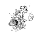
- FIG. 1 is a perspective view of a motor device 1 according to an embodiment of the present invention.
- FIG. 2 is a partial perspective view of the motor device showing a part of the gear unit of FIG. 1 in cross section. It is the fragmentary perspective view which showed the gear housing before installing the pulse output board
- FIG. 6 is a perspective view after the pulse output substrate is installed in FIG. 5. It is the side view which expanded and showed the pulse output board
- substrate is a partial perspective view of the motor device showing a part of the gear unit of FIG.
- FIG. 1 is a perspective view of a motor device 1 according to an embodiment of the present invention.
- the motor device 1 includes a motor 2, a power feeding connector 4, and a gear unit 6.
- the gear unit 6 is, for example, a speed reducer, and the motor device 1 is a DC motor device with a waterproof gear unit. It is used for driving automotive electrical equipment such as electric sliding doors.
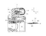
- FIG. 2 is a partial perspective view of the motor device 1 showing a part of the gear unit 6 of FIG. 1 in cross section.
- the motor 2 includes a motor case 8, a drive shaft 10, and an end bell cap 12.
- the motor case 8 has a motor case opening end 14 provided with a flange.
- the drive shaft 10 and the end bell cap 12 protrude from the motor case 8 through a motor case opening end 14 from a completed rotor (not shown).
- the end bell cap 12 is composed of an end bell, a brush holder, a brush, a terminal (all not shown), and the like.
- the power supply connector 4 is resin-molded integrally with a gear housing (housing) 16 described later, and has a plurality of terminals 18 and a bottomed cylindrical connector mounting portion 20.
- the terminals 18 are made of metal and are, for example, four insert-molded in the gear housing 16. From the bottom of the connector mounting portion 20, the connection terminals 18 a of the terminals 18 are directed toward the motor 2 along the axial direction X of the drive shaft 10. Protruding. By attaching an external connector (not shown) to the connector attaching portion 20, it is possible to energize the terminal 18 and thus the pulse output board 22 described later from the connection terminal 18a.
- the gear unit 6 includes a gear housing 16 and a gear train 24 accommodated in the gear housing 16.
- the gear housing 16 has a gear housing opening end 26.
- the drive shaft 10 extends from the motor 2 toward the gear unit 6, and the flange of the motor case opening end 14 is bolted to the gear housing opening end 26 from the axial direction X.
- the gear train 24 includes a worm 28 fixed to the drive shaft 10 and a worm wheel 30 meshed with the worm 28.
- the worm wheel 30 includes an output shaft 31 erected from the center of the wheel main body, and a gear portion 31 a is formed on the outer periphery of the distal end portion of the output shaft 31.
- the gear portion 31a is disposed outside the motor device 1 and meshed with a gear portion of a rotating member (for example, a shaft of a cable drum) connected to a driven device (not shown).
- the rotational driving force of the motor 2 is transmitted to the rotating member, that is, the external driven device via the driving shaft 10 through the worm 28, the worm wheel 30 and the output shaft 31 in order.
- the rotation of the worm wheel 30 may be transmitted to the output shaft 31 via a buffer rubber or the like (not shown).
- a sensor housing portion 32, a shaft housing portion 34, and a gear housing portion 36 are formed in the gear housing 16 as communicating spaces.
- the sensor housing portion 32 is formed at a position adjacent to the power supply connector 4 in the radial direction Y (vertical direction as viewed in FIG. 2) of the drive shaft 10 and is opened by the gear housing opening end 26.
- the end bell cap 12 projecting from the head, the pulse output substrate 22, the sensor magnet 38, which will be described later, and the like are accommodated.
- the shaft accommodating portion 34 extends from the sensor accommodating portion 32 in the direction opposite to the motor 2 along the axial direction X, has a shape whose diameter is reduced from the sensor accommodating portion 32, and accommodates the drive shaft 10, the worm 28, and the like. Yes.
- the gear housing part 36 extends from the shaft housing part 34 along the radial direction Y in the opposite direction to the power supply connector 4 and houses the worm wheel 30 and the like.
- the sensor magnet 38 accommodated in the sensor accommodating portion 32 is formed in an annular shape and fixed to the drive shaft 10 so as to be integrally rotatable, and generates a magnetic flux while rotating integrally with the drive shaft 10.
- the pulse output board 22 is positioned in the sensor housing portion 32 in the vicinity of the sensor magnet 38 so as to face the sensor magnet 38 in the radial direction Y.
- FIG. 3 is a partial perspective view showing a part of the gear housing 16 before the pulse output board 22 is installed
- FIG. 4 is a perspective view after the pulse output board 22 is installed in FIG.
- the pulse output substrate 22 is a single-sided mounting substrate in which patterns, elements, etc. exist only on one side, and has a magnetically permeable base 40.
- a GMR element (rotation detecting element) 41 for detecting the rotation of the sensor magnet 38 based on a change in magnetic flux and an electronic chip such as a capacitor or a diode (not shown) are mounted.
- the GMR element 41 is a giant magnetoresistive element, and is a semiconductor element that utilizes the giant magnetoresistive effect that has a particularly large degree of relative change among the magnetoresistive effects in which the electrical resistance of a substance changes due to a magnetic field.
- a pulse based on the rotation of the magnet 38 is output to a rotation speed control unit (not shown) of the motor 2.
- Each terminal 18 opens to the connection terminal 18a, the vertical part 18b bent in the radial direction Y from the connection terminal 18a and partially embedded in the power supply connector 4, and the sensor housing part 32, and outputs a pulse. And an insertion portion 18c into which the substrate 22 is inserted.
- the insertion portion 18 c moves the pulse output board 22 near the sensor magnet 38 with the back surface 40 b of the mounting surface 40 a of the base 40 facing the sensor magnet 38 as the pulse output board 22 is inserted. (See FIG. 2), and the pulse output substrate 22 is electrically connected to allow the pulse output substrate 22 to be energized.
- FIG. 5 is a partial perspective view showing the gear housing 16 from the gear housing opening end 26 side before the pulse output board 22 is installed
- FIG. 6 is a perspective view after the pulse output board 22 is installed in FIG. FIG.
- each terminal 18 has a contact terminal 42, and the four contact terminals 42 of each terminal 18 are arranged in the radial direction Z of the drive shaft 10 (left and right direction as viewed in FIGS. 5 and 6).
- the insertion portion 18c is formed by sandwiching the mounting surface 40a and the back surface 40b of the pulse output substrate 22 in parallel.
- a substrate guide groove (insertion restricting portion) 43 is formed in the side surface of the sensor housing portion 32 in the gear housing 16.
- the pulse output substrate 22 is accommodated in the sensor accommodating portion 32.
- An abutting portion 43a is formed in the substrate guide groove 43, and when the pulse output substrate 22 is inserted into the substrate guide groove 43, the insertion depth of the pulse output substrate 22 with respect to the insertion portion 18c is limited. That is, the insertion depth of the pulse output substrate 22 with respect to the insertion portion 18 c is defined by the position of the abutting portion 43 a in the substrate guide groove 43.
- FIG. 7 is an enlarged side view showing the pulse output substrate 22 of FIG.
- each contact terminal 42 has a clip shape having an upper movable pin 42a as viewed in FIG. 7 and a lower fixed pin 42b as viewed in FIG.
- the movable pin 42a abuts on the mounting surface 40a, and displacement in a direction away from the fixed pin 42b is allowed to clamp the pulse output substrate 22 between the fixed pin 42b by elastic deformation.
- the fixed pin 42b comes into contact with the back surface 40b and is partially embedded in the gear housing 16 and fixed so as to prevent displacement in a direction away from the movable pin 42a.
- each movable pin 42a is formed with a contact portion 42a2 with respect to the pulse output substrate 22, and the contact portion 42a2 has an arc shape as viewed in FIG.
- the contact area of the movable pin 42a with respect to the pulse output board 22 is reduced, and the pressing force of the movable pin 42a with respect to the mounting surface 40a can be increased, so that the pulse output board 22 is firmly held by the clip-shaped contact terminals 42. It becomes possible.
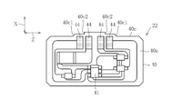
- FIG. 8 is a plan view of the pulse output board 22 as viewed from the mounting surface 40a side.
- the pulse output board 22 has a front end face 40c where the insertion of the pulse output board 22 into the insertion portion 18c is started, and the front end face 40c has an insertion direction of the pulse output board 22 (that is, an axial direction X).
- Two step portions 40c1 and 40c2 that project the front end surface 40c stepwise are provided on the left and right sides.
- the terminal 18 has the insertion portion 18c into which the pulse output substrate 22 is inserted.
- the insertion portion 18c opens to the sensor housing portion 32, and the insertion of the pulse output substrate 22 With the back surface 40b of the mounting surface 40a of the base 40 facing the sensor magnet 38, the pulse output substrate 22 is supported in the vicinity of the sensor magnet 38, and the pulse output substrate 22 is electrically connected and energized.
- the base 40 can prevent the grease and metal foreign matter from being scattered to the pulse output substrate 22 and thus to the GMR element 41. Since the base 40 is made of a magnetically permeable material, the pulse output accuracy from the GMR element 41 is not affected. Thereby, it is not necessary to form a shielding part such as grease on the gear housing 16. Further, since the insertion portion 18c of the pulse output board 22 is formed by the terminal 18, a part such as a sensor holder for fixing and positioning the pulse output board 22 and its locking claw and positioning protrusion is formed in the gear housing 16. do not have to.
- the insertion portion 18c allows the pulse output substrate 22 to be positioned and energized at the same time by sandwiching the mounting surface 40a and the back surface 40b of the pulse output substrate 22 with the contact terminal 42 of the terminal 18.
- the holding of the pulse output substrate 22 by the contact terminal 42 is performed by the movable pin 42a that contacts the mounting surface 40a and the fixed pin 42b that contacts the back surface 40b.
- the movable pin 42a is allowed to be displaced in a direction away from the fixed pin 42b so as to sandwich the pulse output substrate 22 with the fixed pin 42b by elastic deformation, and allows the pulse output substrate 22 to be inserted into the insertion portion 18c. .
- the fixed pin 42b is fixed to the gear housing 16 so as to prevent displacement in a direction away from the movable pin 42a.
- the distance D1 between the back surface 40b and the sensor magnet 38 becomes constant. Since the thickness t of the pulse output substrate 22 is constant, the distance D2 that is the sum of the distance D1 and the thickness t is maintained as the separation distance between the GMR element 41 and the sensor magnet 38.
- the insertion depth of the pulse output substrate 22 with respect to the insertion portion 18c can be defined by the substrate guide groove 43. As a result, it is possible to prevent the pulse output substrate 22 from being pushed too much into the insertion portion 18c and the distance D2 to fluctuate, thereby reducing the pulse output accuracy and hence the rotation speed detection accuracy of the motor 2.
- each electrode portion 44 and the base 40 of the front portion thereof are provided.
- the contact terminals 42 are contacted in stages. Thereby, the insertion load to the pulse output substrate 22 is temporally dispersed, and it is possible to prevent the pulse output substrate 22 from being broken and damaged with the insertion into the insertion portion 18c.
- the present invention is not limited to the above embodiment, and various modifications can be made.
- the insertion portion 18c is formed by the four contact terminals 42 of each terminal 18.
- the number of the terminals 18 and the contact terminals 42 is not limited. It is not limited to that by the terminal 42.
- the GMR element 41 is used for detecting the rotational speed of the sensor magnet 38, but another magnetic sensor (for example, a Hall element) may be used instead of the GMR element 41.
- the pulse output substrate 22 is a single-sided mounting substrate in which the pattern, the 41 GMR elements, and other electronic chips are all present on only one side which is the mounting surface 40a.
- the specification of the pulse output substrate 22 is not limited to this, and it is sufficient that at least the GMR element 41 is mounted on the mounting surface 40a, and an electronic chip other than the pattern and the GMR element 41 exists on the back surface 40b of the mounting surface 40a. May be.
- the stepped portions 40c1 and 40c2 are provided on the front end surface 40c of the pulse output substrate 22.
- the present invention is not limited to this. Instead of providing the stepped portions 40c1 and 40c2 on the front end surface 40c of the pulse output board 22, the length of the movable pin 42a of each contact terminal 42 is changed as shown in FIG.
- the contact part 42a2 may be brought into contact with different positions of the pulse output substrate 22 in stages in the insertion direction of the substrate 22.
- the insertion load on the pulse output substrate 22 by each contact terminal 42 can be dispersed in time to prevent breakage of the pulse output substrate 22 such as breakage. It is.
Landscapes
- Engineering & Computer Science (AREA)
- Power Engineering (AREA)
- Microelectronics & Electronic Packaging (AREA)
- Transmission And Conversion Of Sensor Element Output (AREA)
Abstract
L'invention porte sur un dispositif de moteur (1) équipé : d'un aimant de capteur (38) qui tourne d'un seul tenant avec l'arbre de transmission (10) d'un moteur (2) ; d'un logement (16) comportant une section de logement de capteur (32) dans laquelle l'aimant de capteur est positionné ; d'un substrat de sortie d'impulsions (22), comportant une base magnétiquement perméable (40) et un élément de détection de rotation (41) qui est monté sur une surface de montage (40a) de la base, et qui détecte la rotation de l'aimant de capteur et délivre en sortie une impulsion ; et d'une borne (18) électriquement connectée au substrat de sortie d'impulsions. La borne comporte une section d'insertion (18c) dans laquelle le substrat de sortie d'impulsions est inséré. La section d'insertion débouche dans la section de logement de capteur, soutient le substrat de sortie d'impulsions au voisinage de l'aimant de capteur, la surface arrière (40b) de la surface de montage de la base étant en regard de l'aimant de capteur, quand le substrat de sortie d'impulsions est inséré, et connecte électriquement le substrat de sortie d'impulsions.
Priority Applications (3)
| Application Number | Priority Date | Filing Date | Title |
|---|---|---|---|
| US15/549,112 US10447118B2 (en) | 2015-02-25 | 2016-01-26 | Motor apparatus |
| CN201680004570.5A CN107112863B (zh) | 2015-02-25 | 2016-01-26 | 电机装置 |
| DE112016000903.8T DE112016000903B4 (de) | 2015-02-25 | 2016-01-26 | Motorvorrichtung |
Applications Claiming Priority (2)
| Application Number | Priority Date | Filing Date | Title |
|---|---|---|---|
| JP2015-035271 | 2015-02-25 | ||
| JP2015035271A JP6319848B2 (ja) | 2015-02-25 | 2015-02-25 | モータ装置 |
Publications (1)
| Publication Number | Publication Date |
|---|---|
| WO2016136362A1 true WO2016136362A1 (fr) | 2016-09-01 |
Family
ID=56788409
Family Applications (1)
| Application Number | Title | Priority Date | Filing Date |
|---|---|---|---|
| PCT/JP2016/052169 Ceased WO2016136362A1 (fr) | 2015-02-25 | 2016-01-26 | Dispositif de moteur |
Country Status (5)
| Country | Link |
|---|---|
| US (1) | US10447118B2 (fr) |
| JP (1) | JP6319848B2 (fr) |
| CN (1) | CN107112863B (fr) |
| DE (1) | DE112016000903B4 (fr) |
| WO (1) | WO2016136362A1 (fr) |
Families Citing this family (3)
| Publication number | Priority date | Publication date | Assignee | Title |
|---|---|---|---|---|
| JP7134650B2 (ja) | 2018-03-08 | 2022-09-12 | ミネベアミツミ株式会社 | 回転装置、回転装置の取付構造、及び回転装置と外部コネクタとの接続構造 |
| CN110620303B (zh) * | 2018-09-30 | 2021-05-18 | 中航光电科技股份有限公司 | 一种连接器组件及其插座连接器 |
| DE102019102536A1 (de) * | 2019-02-01 | 2020-08-06 | Nidec Motors & Actuators (Germany) Gmbh | Verstellantrieb aufweisend eine Bürstenkartenanordnung mit integrierter Leiterplatte |
Citations (6)
| Publication number | Priority date | Publication date | Assignee | Title |
|---|---|---|---|---|
| JPH02199780A (ja) * | 1989-01-30 | 1990-08-08 | Yazaki Corp | 低挿入力端子 |
| JPH05115148A (ja) * | 1991-10-22 | 1993-05-07 | Mabuchi Motor Co Ltd | 小型モータ |
| JPH11215774A (ja) * | 1998-01-26 | 1999-08-06 | Mitsuba Corp | 回転検知装置付きの電動モータ |
| JP2004166481A (ja) * | 2002-09-17 | 2004-06-10 | Asmo Co Ltd | モータ及びパワーウインドモータ |
| JP2008167052A (ja) * | 2006-12-27 | 2008-07-17 | Sanyo Electric Co Ltd | 回路装置及びデジタル放送受信装置 |
| JP2014130755A (ja) * | 2012-12-28 | 2014-07-10 | Japan Aviation Electronics Industry Ltd | コネクタ |
Family Cites Families (8)
| Publication number | Priority date | Publication date | Assignee | Title |
|---|---|---|---|---|
| JPS63235812A (ja) * | 1987-03-25 | 1988-09-30 | Hitachi Ltd | 磁気式エンコ−ダ |
| FR2765043B1 (fr) | 1997-06-24 | 2001-02-16 | Rockwell Lvs | Motoreducteur d'activation d'un organe fonctionnel de vehicule automobile |
| JP4121108B2 (ja) | 2001-05-31 | 2008-07-23 | 株式会社ミツバ | 小型モータ |
| US6903473B2 (en) * | 2002-09-17 | 2005-06-07 | Asmo Co. Ltd. | Motor having connector housing |
| US7187095B2 (en) | 2004-02-24 | 2007-03-06 | Asmo Co., Ltd. | Motor, control circuit member and manufacturing method of motor |
| US20070252487A1 (en) * | 2006-04-28 | 2007-11-01 | Nidec Corporation | Motor and pump having magnetic sensor, connecting method between circuit board having magnetic sensor and stator, and manufacturing method of motor and pump |
| CN201877902U (zh) * | 2010-12-16 | 2011-06-22 | 元山科技工业股份有限公司 | 马达定子 |
| WO2016006077A1 (fr) * | 2014-07-10 | 2016-01-14 | 三菱電機株式会社 | Stator de moteur électrique, moteur électrique, et appareil de conditionnement d'air |
-
2015
- 2015-02-25 JP JP2015035271A patent/JP6319848B2/ja active Active
-
2016
- 2016-01-26 WO PCT/JP2016/052169 patent/WO2016136362A1/fr not_active Ceased
- 2016-01-26 CN CN201680004570.5A patent/CN107112863B/zh active Active
- 2016-01-26 DE DE112016000903.8T patent/DE112016000903B4/de active Active
- 2016-01-26 US US15/549,112 patent/US10447118B2/en active Active
Patent Citations (6)
| Publication number | Priority date | Publication date | Assignee | Title |
|---|---|---|---|---|
| JPH02199780A (ja) * | 1989-01-30 | 1990-08-08 | Yazaki Corp | 低挿入力端子 |
| JPH05115148A (ja) * | 1991-10-22 | 1993-05-07 | Mabuchi Motor Co Ltd | 小型モータ |
| JPH11215774A (ja) * | 1998-01-26 | 1999-08-06 | Mitsuba Corp | 回転検知装置付きの電動モータ |
| JP2004166481A (ja) * | 2002-09-17 | 2004-06-10 | Asmo Co Ltd | モータ及びパワーウインドモータ |
| JP2008167052A (ja) * | 2006-12-27 | 2008-07-17 | Sanyo Electric Co Ltd | 回路装置及びデジタル放送受信装置 |
| JP2014130755A (ja) * | 2012-12-28 | 2014-07-10 | Japan Aviation Electronics Industry Ltd | コネクタ |
Also Published As
| Publication number | Publication date |
|---|---|
| JP2016158417A (ja) | 2016-09-01 |
| DE112016000903B4 (de) | 2022-11-10 |
| CN107112863B (zh) | 2019-05-28 |
| DE112016000903T5 (de) | 2017-11-09 |
| CN107112863A (zh) | 2017-08-29 |
| US10447118B2 (en) | 2019-10-15 |
| JP6319848B2 (ja) | 2018-05-09 |
| US20180026497A1 (en) | 2018-01-25 |
Similar Documents
| Publication | Publication Date | Title |
|---|---|---|
| US10494014B2 (en) | Motor including nonmagnetic contamination cover and electric power steering device including same | |
| JP3794937B2 (ja) | 回転検出装置 | |
| JP5006714B2 (ja) | ブラシ付き電動モータ | |
| JP6635338B2 (ja) | 回転装置 | |
| CN112398286B (zh) | 用于测量机轴的角位置的装置 | |
| JP6702212B2 (ja) | 駆動装置 | |
| KR20180026512A (ko) | 전동 구동 장치 및 전동 파워 스티어링 장치 | |
| CN104737424A (zh) | 用于驱动装置的连接元件以及具有连接件的驱动装置 | |
| JP6319848B2 (ja) | モータ装置 | |
| JP4697597B2 (ja) | ブスバーおよびモータ | |
| JP2009201277A (ja) | 減速機構付き電動モータ | |
| CN110832753B (zh) | 马达装置的制造方法以及马达装置 | |
| JP4556651B2 (ja) | 電子制御装置、電子制御装置付電動機 | |
| JP5139206B2 (ja) | 電動モータ | |
| JP4702593B2 (ja) | モータ | |
| JP5731861B2 (ja) | 給電手段、およびモータユニット | |
| CN213717789U (zh) | 电动机 | |
| JP2008141914A (ja) | モータ装置 | |
| JP5602507B2 (ja) | ブラシ付き電動モータ | |
| JP6227375B2 (ja) | モータ | |
| JP2018007387A (ja) | モータ装置 | |
| JP6169937B2 (ja) | 制御回路付きモータの検査方法 | |
| JP4860208B2 (ja) | 回路部品の製造方法 | |
| JP2018017667A (ja) | 電流センサモジュール | |
| JP2014014274A (ja) | 制御回路部材 |
Legal Events
| Date | Code | Title | Description |
|---|---|---|---|
| 121 | Ep: the epo has been informed by wipo that ep was designated in this application |
Ref document number: 16755112 Country of ref document: EP Kind code of ref document: A1 |
|
| WWE | Wipo information: entry into national phase |
Ref document number: 15549112 Country of ref document: US |
|
| WWE | Wipo information: entry into national phase |
Ref document number: 112016000903 Country of ref document: DE |
|
| 122 | Ep: pct application non-entry in european phase |
Ref document number: 16755112 Country of ref document: EP Kind code of ref document: A1 |