WO2016136490A1 - Mécanisme anti-retour et moteur comprenant un réducteur de vitesse - Google Patents
Mécanisme anti-retour et moteur comprenant un réducteur de vitesse Download PDFInfo
- Publication number
- WO2016136490A1 WO2016136490A1 PCT/JP2016/054071 JP2016054071W WO2016136490A1 WO 2016136490 A1 WO2016136490 A1 WO 2016136490A1 JP 2016054071 W JP2016054071 W JP 2016054071W WO 2016136490 A1 WO2016136490 A1 WO 2016136490A1
- Authority
- WO
- WIPO (PCT)
- Prior art keywords
- reverse rotation
- output
- lock plate
- prevention mechanism
- motor
- Prior art date
- Legal status (The legal status is an assumption and is not a legal conclusion. Google has not performed a legal analysis and makes no representation as to the accuracy of the status listed.)
- Ceased
Links
Images


Classifications
-
- E—FIXED CONSTRUCTIONS
- E05—LOCKS; KEYS; WINDOW OR DOOR FITTINGS; SAFES
- E05F—DEVICES FOR MOVING WINGS INTO OPEN OR CLOSED POSITION; CHECKS FOR WINGS; WING FITTINGS NOT OTHERWISE PROVIDED FOR, CONCERNED WITH THE FUNCTIONING OF THE WING
- E05F15/00—Power-operated mechanisms for wings
- E05F15/60—Power-operated mechanisms for wings using electrical actuators
- E05F15/603—Power-operated mechanisms for wings using electrical actuators using rotary electromotors
- E05F15/665—Power-operated mechanisms for wings using electrical actuators using rotary electromotors for vertically-sliding wings
- E05F15/689—Power-operated mechanisms for wings using electrical actuators using rotary electromotors for vertically-sliding wings specially adapted for vehicle windows
- E05F15/697—Motor units therefor, e.g. geared motors
-
- F—MECHANICAL ENGINEERING; LIGHTING; HEATING; WEAPONS; BLASTING
- F16—ENGINEERING ELEMENTS AND UNITS; GENERAL MEASURES FOR PRODUCING AND MAINTAINING EFFECTIVE FUNCTIONING OF MACHINES OR INSTALLATIONS; THERMAL INSULATION IN GENERAL
- F16D—COUPLINGS FOR TRANSMITTING ROTATION; CLUTCHES; BRAKES
- F16D51/00—Brakes with outwardly-movable braking members co-operating with the inner surface of a drum or the like
- F16D51/46—Self-tightening brakes with pivoted brake shoes, i.e. the braked member increases the braking action
- F16D51/60—Self-tightening brakes with pivoted brake shoes, i.e. the braked member increases the braking action with wedging action of a brake-shoe, e.g. the shoe entering as a wedge between the brake-drum and a stationary part
- F16D51/62—Self-tightening brakes with pivoted brake shoes, i.e. the braked member increases the braking action with wedging action of a brake-shoe, e.g. the shoe entering as a wedge between the brake-drum and a stationary part mechanically actuated
-
- F—MECHANICAL ENGINEERING; LIGHTING; HEATING; WEAPONS; BLASTING
- F16—ENGINEERING ELEMENTS AND UNITS; GENERAL MEASURES FOR PRODUCING AND MAINTAINING EFFECTIVE FUNCTIONING OF MACHINES OR INSTALLATIONS; THERMAL INSULATION IN GENERAL
- F16D—COUPLINGS FOR TRANSMITTING ROTATION; CLUTCHES; BRAKES
- F16D59/00—Self-acting brakes, e.g. coming into operation at a predetermined speed
-
- F—MECHANICAL ENGINEERING; LIGHTING; HEATING; WEAPONS; BLASTING
- F16—ENGINEERING ELEMENTS AND UNITS; GENERAL MEASURES FOR PRODUCING AND MAINTAINING EFFECTIVE FUNCTIONING OF MACHINES OR INSTALLATIONS; THERMAL INSULATION IN GENERAL
- F16D—COUPLINGS FOR TRANSMITTING ROTATION; CLUTCHES; BRAKES
- F16D63/00—Brakes not otherwise provided for; Brakes combining more than one of the types of groups F16D49/00 - F16D61/00
- F16D63/006—Positive locking brakes
-
- F—MECHANICAL ENGINEERING; LIGHTING; HEATING; WEAPONS; BLASTING
- F16—ENGINEERING ELEMENTS AND UNITS; GENERAL MEASURES FOR PRODUCING AND MAINTAINING EFFECTIVE FUNCTIONING OF MACHINES OR INSTALLATIONS; THERMAL INSULATION IN GENERAL
- F16D—COUPLINGS FOR TRANSMITTING ROTATION; CLUTCHES; BRAKES
- F16D65/00—Parts or details
- F16D65/14—Actuating mechanisms for brakes; Means for initiating operation at a predetermined position
- F16D65/16—Actuating mechanisms for brakes; Means for initiating operation at a predetermined position arranged in or on the brake
- F16D65/22—Actuating mechanisms for brakes; Means for initiating operation at a predetermined position arranged in or on the brake adapted for pressing members apart, e.g. for drum brakes
-
- F—MECHANICAL ENGINEERING; LIGHTING; HEATING; WEAPONS; BLASTING
- F16—ENGINEERING ELEMENTS AND UNITS; GENERAL MEASURES FOR PRODUCING AND MAINTAINING EFFECTIVE FUNCTIONING OF MACHINES OR INSTALLATIONS; THERMAL INSULATION IN GENERAL
- F16H—GEARING
- F16H1/00—Toothed gearings for conveying rotary motion
- F16H1/02—Toothed gearings for conveying rotary motion without gears having orbital motion
- F16H1/04—Toothed gearings for conveying rotary motion without gears having orbital motion involving only two intermeshing members
- F16H1/12—Toothed gearings for conveying rotary motion without gears having orbital motion involving only two intermeshing members with non-parallel axes
- F16H1/16—Toothed gearings for conveying rotary motion without gears having orbital motion involving only two intermeshing members with non-parallel axes comprising worm and worm-wheel
-
- E—FIXED CONSTRUCTIONS
- E05—LOCKS; KEYS; WINDOW OR DOOR FITTINGS; SAFES
- E05Y—INDEXING SCHEME ASSOCIATED WITH SUBCLASSES E05D AND E05F, RELATING TO CONSTRUCTION ELEMENTS, ELECTRIC CONTROL, POWER SUPPLY, POWER SIGNAL OR TRANSMISSION, USER INTERFACES, MOUNTING OR COUPLING, DETAILS, ACCESSORIES, AUXILIARY OPERATIONS NOT OTHERWISE PROVIDED FOR, APPLICATION THEREOF
- E05Y2201/00—Constructional elements; Accessories therefor
- E05Y2201/20—Brakes; Disengaging means; Holders; Stops; Valves; Accessories therefor
- E05Y2201/214—Disengaging means
- E05Y2201/216—Clutches
-
- E—FIXED CONSTRUCTIONS
- E05—LOCKS; KEYS; WINDOW OR DOOR FITTINGS; SAFES
- E05Y—INDEXING SCHEME ASSOCIATED WITH SUBCLASSES E05D AND E05F, RELATING TO CONSTRUCTION ELEMENTS, ELECTRIC CONTROL, POWER SUPPLY, POWER SIGNAL OR TRANSMISSION, USER INTERFACES, MOUNTING OR COUPLING, DETAILS, ACCESSORIES, AUXILIARY OPERATIONS NOT OTHERWISE PROVIDED FOR, APPLICATION THEREOF
- E05Y2400/00—Electronic control; Electrical power; Power supply; Power or signal transmission; User interfaces
- E05Y2400/10—Electronic control
- E05Y2400/52—Safety arrangements associated with the wing motor
- E05Y2400/522—Back-drive prevention
-
- E—FIXED CONSTRUCTIONS
- E05—LOCKS; KEYS; WINDOW OR DOOR FITTINGS; SAFES
- E05Y—INDEXING SCHEME ASSOCIATED WITH SUBCLASSES E05D AND E05F, RELATING TO CONSTRUCTION ELEMENTS, ELECTRIC CONTROL, POWER SUPPLY, POWER SIGNAL OR TRANSMISSION, USER INTERFACES, MOUNTING OR COUPLING, DETAILS, ACCESSORIES, AUXILIARY OPERATIONS NOT OTHERWISE PROVIDED FOR, APPLICATION THEREOF
- E05Y2900/00—Application of doors, windows, wings or fittings thereof
- E05Y2900/50—Application of doors, windows, wings or fittings thereof for vehicles
- E05Y2900/53—Type of wing
- E05Y2900/55—Windows
-
- F—MECHANICAL ENGINEERING; LIGHTING; HEATING; WEAPONS; BLASTING
- F16—ENGINEERING ELEMENTS AND UNITS; GENERAL MEASURES FOR PRODUCING AND MAINTAINING EFFECTIVE FUNCTIONING OF MACHINES OR INSTALLATIONS; THERMAL INSULATION IN GENERAL
- F16D—COUPLINGS FOR TRANSMITTING ROTATION; CLUTCHES; BRAKES
- F16D2127/00—Auxiliary mechanisms
- F16D2127/001—Auxiliary mechanisms for automatic or self-acting brake operation
- F16D2127/004—Auxiliary mechanisms for automatic or self-acting brake operation direction-responsive
Definitions
- the present invention relates to a motor reverse rotation prevention mechanism used for opening and closing a vehicle power window or sunroof, for example.
- a motor equipped with a reduction gear composed of a worm and a worm wheel is known.
- Such a motor with a reduction gear is used, for example, to prevent the window glass from being opened by its own weight or vibration or opened from the outside when used in a power window of an automobile that moves the window glass up and down to open and close.
- reversal resistance is required.
- the lock plate is pressed toward the facing material side by the wave washer. For this reason, even when the motor is driven, the lock plate slides against the facing material, so that transmission torque loss occurs. In addition, wear of the facing material and the lock plate due to sliding is a cause of instability of frictional force due to the generation of foreign matter and a decrease in life.
- the present invention has been made in view of such circumstances, and an object of the present invention is to provide a mechanism that realizes stable inversion resistance.
- a reverse rotation prevention mechanism is a reverse rotation prevention mechanism provided in a torque transmission path between an output shaft and a drive shaft of a motor, and an external force is applied to the output shaft.
- the first frictional force generator configured to suppress the rotation of the braking rotary member provided in the torque transmission path from rotating relative to other members.
- a second frictional force generator configured to generate a braking force that prevents reverse rotation when part of the braking rotating member is pressed.
- the first frictional force generator is provided in a different area from the second frictional force generator.
- the second friction generating portion can be configured to generate a braking force that mainly prevents reverse rotation.
- the first friction generating portion can be configured to mainly restrain the braking rotary member from rotating relative to the other members.
- the other member may be a fixed member that does not rotate, and the first frictional force generator may be provided between the braking rotary member and the fixed member.
- the braking rotating member is less likely to move with respect to the fixed member, and the braking rotating member can be prevented from rotating with another rotating body when an external force is applied to the output shaft.
- the other member may be a drive shaft side rotation member provided on the drive shaft side of the motor relative to the braking rotation member in the torque transmission path.
- the drive shaft side rotation member may engage with the brake rotation member and rotate together.
- the first frictional force generator may be provided between the braking rotary member and the drive shaft side rotary member.
- the motor When the motor is driven, it may further include a separation mechanism that separates a part of the braking rotating member from the second frictional force generation unit. Thereby, the braking force by the second frictional force generator is reduced when the motor is driven.
- a part of the braking rotating member may be a surface having a taper with respect to the central axis of the braking rotating member. Thereby, a part of the braking rotary member can generate a pressing force in a direction different from the direction in which the braking rotary member is pressed.
- the taper surface may have a taper angle of 1 degree to less than 30 degrees. Thereby, a large pressing force can be generated.
- a brake pressing member configured to be separated from the braking rotating member by a reaction force of the force pressing the braking rotating member against the second frictional force generating portion when an external force is applied to the output shaft;
- a third frictional force generator configured to generate a braking force that prevents reverse rotation by pressing a part of the braking pressing member when an external force is applied may be provided. Thereby, a larger braking force can be generated.
- This reverse rotation prevention mechanism is a reverse rotation prevention mechanism provided in the torque transmission path between the output shaft and the motor drive shaft.
- the rotation for braking provided in the torque transmission path is provided.
- a frictional force generator configured to generate a braking force that prevents reverse rotation when part of the member is pressed, and a part of the braking rotating member separated from the frictional force generator when the motor is driven. And a separating mechanism.
- the braking force generated by the frictional force generator is reduced when the motor is driven.
- a motor a worm that transmits the rotational force of the drive shaft of the motor, a worm wheel that meshes with the worm, an output shaft that transmits the rotational force acting on the worm wheel, and a reverse rotation prevention mechanism may be provided.
- a motor By applying such a motor to, for example, opening and closing of a power window or a sunroof of a vehicle, it is possible to prevent a situation in which the window is opened by its own weight or vibration or opened from the outside.
- the reverse rotation prevention mechanism may be provided in a torque transmission path between the motor drive shaft and the worm. Thereby, the external force applied to the output shaft is reduced by the worm and the worm wheel and acts on the reverse rotation prevention mechanism, so that the strength of the members constituting the reverse rotation prevention mechanism can be reduced.
- the reverse rotation prevention mechanism may be provided in the torque transmission path between the worm wheel and the output shaft. Accordingly, by causing a part of the function of the reverse rotation prevention mechanism to be assigned to an existing part such as a worm wheel, an increase in the number of parts accompanying the addition of the reverse rotation prevention mechanism can be suppressed.
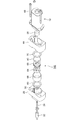
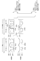
- FIG. 1A is a perspective view of a motor with a speed reducer
- FIG. 1B is a perspective view of the motor with a speed reducer viewed from a direction different from that in FIG. It is a fragmentary sectional view of the motor with a reduction gear concerning a 1st embodiment.
- FIG. 3 is an enlarged cross-sectional view in the vicinity of a reverse rotation prevention mechanism shown in FIG. 2.
- Fig.5 (a) is a perspective view of a 1st casing
- FIG.5 (b) is a perspective view of the 1st casing seen from the direction different from Fig.5 (a).
- FIG. 11A is a perspective view of the output plate
- FIG. 11B is a perspective view of the output plate viewed from a different direction from FIG. 11A
- 12A is an AA cross-sectional view of the output plate shown in FIG. 11A
- FIG. 12B is a BB cross-sectional view of the output plate shown in FIG. 11A
- FIG. 13A is a perspective view of the lock plate
- FIG. 13B is a perspective view of the lock plate viewed from a different direction from FIG. 13A.
- 14A is a CC cross-sectional view of the lock plate shown in FIG. 13A
- FIG. 14B is a DD cross-sectional view of the lock plate shown in FIG. 13A.
- It is a perspective view of a lock plate side brake material. It is sectional drawing of a lock plate side brake material.
- FIG. 17A is a perspective view of the output pin
- FIG. 17B is a perspective view of the output pin viewed from a direction different from that in FIG. 18A is an EE sectional view of the output pin shown in FIG. 17A
- FIG. 18B is an FF sectional view of the output pin shown in FIG. 17A.
- CCW motor counterclockwise
- FIG. 28A is a perspective view of the lock plate according to the second embodiment
- FIG. 28B is a perspective view of the lock plate viewed from a different direction from FIG.
- FIG. 29A is a perspective view of an output pin according to the second embodiment
- FIG. 29B is a perspective view of the output pin viewed from a direction different from FIG. 29A.
- FIG. 36A is a perspective view of an output plate according to the fourth embodiment
- FIG. 36B is a perspective view of the output plate viewed from a direction different from FIG. 36A.
- FIG. 40A is a perspective view of the lock plate according to the fifth embodiment
- FIG. 40B is a perspective view of the lock plate viewed from a different direction from FIG. 41A is a CC cross-sectional view of the lock plate shown in FIG. 40A
- FIG. 41B is a DD cross-sectional view of the lock plate shown in FIG. 40A.
- FIG. 46A is a perspective view of a first casing according to the sixth embodiment
- FIG. 46B is a perspective view of the first casing viewed from a direction different from FIG. 46A.
- FIG. 48A is a perspective view of an output plate according to the sixth embodiment
- FIG. 48A is a perspective view of an output plate according to the sixth embodiment
- 48B is a perspective view of the output plate viewed from a direction different from FIG. 48A.
- 49A is a cross-sectional view taken along line AA of the output plate shown in FIG. 48A
- FIG. 49B is a cross-sectional view taken along line BB of the output plate shown in FIG.
- It is a schematic diagram for demonstrating the motion of the reverse rotation prevention mechanism which concerns on 6th Embodiment when external force is added to an output shaft.
- It is a disassembled perspective view of the reduction gear containing the reverse rotation prevention mechanism which concerns on 7th Embodiment.
- It is an expanded sectional view of the reduction gear shown in FIG.
- It is a perspective view of the casing which concerns on 7th Embodiment.
- FIG. 55A is a perspective view of an output plate side brake member according to the seventh embodiment
- FIG. 55B is a perspective view of the output plate side brake member viewed from a direction different from FIG. 55A.
- It is. 56 (a) is a GG sectional view of the output plate side brake material shown in FIG. 55 (b)
- FIG. 56 (b) is an HH section of the output plate side brake material shown in FIG. 55 (b).
- FIG. FIG. 57A is a perspective view of an output plate according to the seventh embodiment
- FIG. 57B is a perspective view of the output plate viewed from a direction different from FIG. 57A.
- FIG. 58A is an II cross-sectional view of the output plate shown in FIG. 57B
- FIG. 58B is a JJ cross-sectional view of the output plate shown in FIG. 57B.
- FIG. 59A is a perspective view of a lock plate according to the seventh embodiment
- FIG. 59B is a perspective view of the lock plate viewed from a direction different from FIG. 59A.
- 60A is a KK sectional view of the lock plate shown in FIG. 59A
- FIG. 60B is an LL sectional view of the lock plate shown in FIG. 59A.
- 61 (a) is a perspective view of a lock plate side brake member according to a seventh embodiment
- 61 (b) is a perspective view of the lock plate side brake member viewed from a different direction from FIG. 61 (a). It is. 62A is a cross-sectional view taken along line MM of the lock plate side brake material shown in FIG. 61B, and FIG. 62B is a cross-sectional view taken along line NN of the lock plate side brake material shown in FIG. 61B. FIG. It is a perspective view of the worm wheel which concerns on 7th Embodiment. 64A is an OO cross-sectional view of the worm wheel shown in FIG. 63, and FIG. 64B is a PP cross-sectional view of the worm wheel shown in FIG.
- FIG. 67 is a schematic diagram for explaining an operation when the motor is driven in a direction in which the worm wheel rotates counterclockwise (CCW) from a state in which the reverse rotation prevention mechanism shown in FIG. 66 functions.
- FIG. 67 is a schematic diagram for explaining the operation when the motor is driven in the direction in which the worm wheel rotates clockwise (CW) from the state in which the reverse rotation prevention mechanism shown in FIG. 66 functions.
- CW clockwise
- FIG. 70 is an enlarged cross-sectional view of the reduction gear shown in FIG. 69.
- the motor with a speed reducer is applicable to a device that moves an object by decelerating the movement of the motor.
- a reverse rotation resistance of a vehicle power window system, a sunroof, a power seat, a door closure, etc. It is suitable for an apparatus that requires the performance.
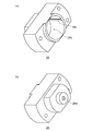
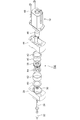
- FIG. 1A is a perspective view of a motor with a speed reducer
- FIG. 1B is a perspective view of the motor with a speed reducer viewed from a direction different from that in FIG.
- the motor 10 with a speed reducer includes a motor 12 that is a DC motor and a speed reducer 14 that is connected to the shaft of the motor 12.
- the speed reducer 14 includes a cylindrical casing 16 that houses a worm wheel described later.
- the speed reducer 14 has an output shaft 18 protruding from one surface of the housing 16.
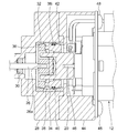
- FIG. 2 is a partial cross-sectional view of the motor with a reduction gear according to the first embodiment.
- the speed reducer 14 of the motor 10 with a speed reducer has a worm 22 to which the rotational force of the drive shaft 20 of the motor 12 is transmitted, a worm wheel 24 meshing with the worm 22, and an output to which the rotational force acting on the worm wheel 24 is transmitted.
- a shaft 18 (see FIG. 1A) and a reverse rotation prevention mechanism 100 are provided.
- the reverse rotation prevention mechanism 100 is provided in a torque transmission path between the drive shaft 20 of the motor 12 and the worm 22.
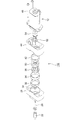
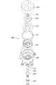
- FIG. 3 is an exploded perspective view of the reverse rotation prevention mechanism 100 according to the first embodiment.
- 4 is an enlarged cross-sectional view of the vicinity of the reverse rotation prevention mechanism shown in FIG.
- the reverse rotation prevention mechanism 100 is provided in a torque transmission path between the drive shaft 20 of the motor 12 and the gear side shaft 26 to which the worm 22 is fixed.
- the reverse rotation prevention mechanism 100 includes a first casing 28, a sintered bearing 30, an output plate side brake member 32, a sleeve 34, an output plate 36, a lock plate 38, an O-ring 40, and a lock plate side brake.
- a material 42, a second casing 44, and an output pin 46 are provided.
- the first casing 28 and the second casing 44 are integrated with the motor 12 with a tapping screw 48.
- FIG. 5A is a perspective view of the first casing 28, and FIG. 5B is a perspective view of the first casing 28 viewed from a direction different from that in FIG. 5A.
- FIG. 6 is a cross-sectional view of the first casing 28.
- the first casing 28 includes a through hole 28a through which the gear side shaft 26 passes, and a cylindrical recess 28b in which the output plate side brake member 32, the sleeve 34, and the lock plate side brake member 42 are accommodated. ing.
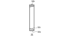
- FIG. 7 is a perspective view of the output plate side brake member 32.
- FIG. 8 is a sectional view of the output plate side brake member 32.
- the output plate side brake member 32 is an annular member and has a constant outer diameter. Further, a groove-like fixing recess 32b parallel to the axial direction is formed on the outer peripheral surface 32a.
- the output plate side brake member 32 has a brake surface 32c which is an inclined surface whose inner diameter changes in the axial direction.
- the output plate side brake member 32 is inserted into the concave portion 28 b of the first casing 28 at a position where the fixing concave portion 32 b is aligned with the fixing convex portion 28 c of the first casing 28.
- FIG. 9 is a perspective view of the sleeve 34.
- FIG. 10 is a cross-sectional view of the sleeve 34.
- the sleeve 34 is an annular member, and a groove-shaped fixing recess 34b parallel to the axial direction is formed on the outer peripheral surface 34a.
- the sleeve 34 is inserted into the concave portion 28 b of the first casing 28 at a position where the fixing concave portion 34 b is aligned with the fixing convex portion 28 c of the first casing 28.
- [Output plate] 11A is a perspective view of the output plate 36
- FIG. 11B is a perspective view of the output plate 36 viewed from a direction different from that in FIG. 11A
- 12A is an AA cross-sectional view of the output plate 36 shown in FIG. 11A
- FIG. 12B is a BB cross-sectional view of the output plate 36 shown in FIG. 11A.
- the output plate 36 is a cylindrical member, and a through hole 36a into which the gear side shaft 26 is inserted is formed at the center.
- Two arc-shaped through-holes 36b are formed around the central portion where the through-hole 36a is formed so that the output pin 46 can be rotated in both directions around the rotation axis with a part of the output pin 46 entering.
- the through hole 36b has an inner wall 36j that abuts a part of the output pin 46 when the output pin 46 rotates.
- the end surface 36c of the output plate 36 on the side facing the lock plate 38 has four arc-shaped inclined portions 36d formed in the circumferential direction of the outer peripheral portion.
- the inclined portion 36d is configured such that the axial height gradually increases or decreases when the circumferential position changes.
- apex portions 36g or valley portions 36h are alternately formed between two adjacent inclined portions 36d.
- the through hole 36a is configured to allow movement of the gear side shaft 26 in the axial direction in a state where the gear side shaft 26 is inserted.
- a part of the outer peripheral surface 36e of the output plate 36 functions as a brake surface 36f.
- the brake surface 36f according to the present embodiment is a tapered surface.
- FIG. 13A is a perspective view of the lock plate 38
- FIG. 13B is a perspective view of the lock plate 38 as seen from a different direction from FIG. 13A.
- 14A is a CC cross-sectional view of the lock plate 38 shown in FIG. 13A
- FIG. 14B is a DD cross-sectional view of the lock plate 38 shown in FIG. 13A.
- the lock plate 38 is a cylindrical member, and has two arc-shaped through-holes 38b that can rotate in both directions around the rotation axis with a part of the output pin 46 entering around the center portion. Is formed.
- the through hole 38b has an inner wall 38j that comes into contact with a part of the output pin 46 when the output pin 46 rotates.
- four inclined portions 38k constituting a separation mechanism for separating the lock plate 38 from the lock plate side brake member 42 are formed.
- An end surface 38c of the lock plate 38 on the side facing the output plate 36 has four inclined portions 38d formed in the circumferential direction of the outer peripheral portion.
- the inclined portion 38d is configured such that the axial height gradually increases or decreases when the circumferential position changes.
- a top 38g or a valley 38h is formed between two adjacent inclined portions 38d.
- a part of the outer peripheral surface 38e of the lock plate 38 functions as a brake surface 38f.
- the brake surface 38f according to the present embodiment is a tapered surface.
- a groove 38 i in which the O-ring 40 is mounted is formed on the outer peripheral surface 38 e of the lock plate 38.
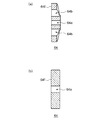
- FIG. 15 is a perspective view of the lock plate side brake member 42.
- FIG. 16 is a cross-sectional view of the lock plate side brake member 42.
- the lock plate side brake member 42 is an annular member, and the outer diameter is constant. Further, a groove-like fixing recess 42b parallel to the axial direction is formed on the outer peripheral surface 42a.
- the lock plate side brake member 42 has a brake surface 42c that is an inclined surface whose inner diameter changes in the axial direction.
- the lock plate-side brake member 42 is inserted into the recess 28 b of the first casing 28 at a position where the fixing recess 42 b is aligned with the fixing protrusion 28 c of the first casing 28.
- [Output pin] 17A is a perspective view of the output pin 46
- FIG. 17B is a perspective view of the output pin 46 viewed from a direction different from FIG. 17A.
- 18A is an EE sectional view of the output pin 46 shown in FIG. 17A
- FIG. 18B is an FF sectional view of the output pin 46 shown in FIG. 17A.
- the output pin 46 has a cylindrical main body portion 46a and two convex engaging portions 46c provided so as to protrude in the axial direction from one end face 46b of the main body portion 46a.
- a press-fitting hole 46e into which the drive shaft 20 is press-fitted is formed on the other end surface 46d of the main body 46a.
- the convex engaging portion 46 c has a shape that can be rotated while entering the through hole 38 b of the lock plate 38 and the through hole 36 b of the output plate 36. Further, the convex engagement portion 46c has engagement surfaces 46f and 46g that engage with the inner wall of the through hole 38b of the lock plate 38 and the inner wall of the through hole 36b of the output plate 36 when the motor is driven.
- the end face 46b of the output pin 46 has four arc-shaped inclined portions 46h formed in the circumferential direction of the outer peripheral portion.
- the inclined portion 46h is configured such that the axial height gradually increases or decreases when the circumferential position changes. Further, convex engagement portions 46c or valley portions 46i are alternately formed between two adjacent inclined portions 46h.
- FIG. 19 is an exploded perspective view of a main part of the reverse rotation preventing mechanism according to the first embodiment.
- FIG. 20 is a schematic diagram for explaining the movement of each component when an external force is applied to the output shaft.
- FIG. 20 schematically shows a developed sectional view of the inner diameter side and the outer diameter side of the reverse rotation prevention mechanism of FIG.
- the convex engagement portion 46 c of the output pin 46 is located at the output plate 36 in the through hole 36 b of the output plate 36 and the through hole 38 b of the lock plate 38. And is not in contact with the lock plate 38. In that case, no great force is applied between the components.
- FIG. 21 is a schematic diagram for explaining the movement of the reverse rotation prevention mechanism when an external force is applied to the output shaft.
- the output plate 36 and the gear-side shaft 26 in the reverse rotation prevention mechanism 100 are limited in relative movement in the rotation direction (not relative rotation) while the output plate 36 is allowed to move in the axial direction relative to the gear-side shaft 26.
- the shapes of the through hole 36 a and the D cut portion 26 a that is the tip of the gear side shaft 26 are defined.
- the reverse rotation preventing mechanism 100 configured as described above moves the output plate 36 toward the worm 22 when a force that causes the output plate 36 and the lock plate 38 to separate in the axial direction is generated.
- the lock plate 38 moves to the output pin 46 side.
- the brake surface 36f (see FIG. 11) of the output plate 36 is pressed against the brake surface 32c (see FIG. 7) of the output plate side brake material 32 to generate a friction braking force
- the brake surface 38f ( 13) is pressed against the brake surface 42c (see FIG. 15) of the lock plate side brake member 42, and a friction braking force is generated.
- the stable inversion resistance can be realized. That is, even when an external force is applied to the output shaft 18, a situation in which the output shaft 18 rotates unintentionally can be prevented.
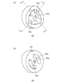
- FIG. 22 is a schematic diagram for explaining the operation when the motor is driven counterclockwise (CCW) from the state where the reverse rotation prevention mechanism shown in FIG. 20 functions.
- FIG. 23 is a schematic diagram for explaining the operation when the motor is driven clockwise (CW) from the state where the reverse rotation prevention mechanism shown in FIG. 20 functions.
- the reverse rotation prevention mechanism according to the present embodiment can suppress the frictional braking force generated when an external force is applied to the output shaft in the case of normal motor drive. And reduction in motor torque transmission efficiency due to frictional resistance can be suppressed.
- the O-ring 40 is attached to the groove 38i formed on the outer peripheral surface of the lock plate 38 and inserted into the sleeve 34 (see FIG. 4 and the like). .
- the force which tries to stay at the position of the lock plate 38 by the frictional resistance between the lock plate 38 and the O-ring 40 and the frictional resistance between the O-ring 40 and the sleeve 34 works. Even if the output plate 36 rotates, it is prevented from rotating.
- FIG. 24 is a schematic diagram for explaining the frictional force generator according to the first embodiment.
- FIG. 25 is a diagram illustrating a relationship between the cone angle ⁇ and the pressing force Y.
- the brake surface 38f of the lock plate 38 is a surface having a taper with respect to the axial direction of the gear side shaft 26 (the central axis direction of the lock plate 38).
- the brake surface 42c of the lock plate side brake member 42 is also a tapered surface.
- the cone (gradient) angle ⁇ shown in FIGS. 24 and 25 is an angle formed by the axial direction and the brake surface, and corresponds to a half of the taper angle formed by the brake surface 38f facing the lock plate 38.
- the lock plate side brake member 42 receives the pressing force Y in the arrow direction from the lock plate 38.
- the brake surface 38f of the lock plate 38 can generate a pressing force Y in a direction different from the direction in which the lock plate 38 is pressed.
- the cone angle ⁇ is appropriately set in consideration of a pressing force for preventing reverse rotation, a friction coefficient, an amplification factor, and the like.
- the brake surface 38f of the lock plate 38 may have a taper angle of 1 to less than 30 degrees (cone angle of 0.5 to less than 15 degrees).
- the friction coefficient is preferably in the range of 0.01 to 0.8. Thereby, a large pressing force Y can be generated.
- the reverse rotation prevention mechanism 100 is provided in the torque transmission path between the output shaft 18 and the drive shaft 20 of the motor.
- the lock plate 38 as a braking rotation member provided in the torque transmission path is applied to the first casing 28.
- the braking force that prevents the reverse rotation by pressing the brake surface 38f of the lock plate 38 is provided.
- a second frictional force generator configured to generate the second frictional force.
- the first frictional force generating portion is composed of a sleeve 34 and an O-ring 40, and is provided between a first casing 28 that is a fixed member that does not rotate and a lock plate 38. . Thereby, it becomes difficult for the lock plate 38 to move with respect to the first casing 28, and when the external force is applied to the output shaft 18, it is possible to suppress the lock plate 38 from rotating with the output plate 36 which is another rotating body. .
- the sleeve 34 can be omitted by making the material and shape of the first casing 28 and the O-ring 40 appropriate.
- the second frictional force generating portion is constituted by the brake surface 42c of the lock plate side brake material 42 and the brake surface 38f of the lock plate 38.
- the first frictional force generating part is provided in a different area from the second frictional force generating part.
- the brake surface 42c can be configured to generate a braking force that mainly prevents reverse rotation. That is, a member that generates high frictional resistance can be employed.
- the O-ring 40 of the first friction generating portion can be configured to mainly restrain the lock plate 38 from rotating relative to the first casing 28. That is, the O-ring 40 can set the frictional resistance with the lock plate 38 to a relatively low size such that the lock plate 38 does not rotate when the output plate 36 rotates.
- the sliding resistance between the O-ring 40 and the sleeve 34 when the motor is driven can be suppressed, and the transmission efficiency of the driving torque of the motor 10 can be improved.
- a material with low frictional resistance can be applied as the O-ring 40, a material with good wear resistance can be selected.
- the reverse rotation prevention mechanism 100 includes a separation mechanism that separates the brake surface 38f of the lock plate 38 from the brake surface 42c of the lock plate side brake member 42 when the motor 12 is driven. Specifically, as the output pin 46 rotates, the inclined portion 46h of the output pin 46 contacts the inclined portion 38k of the lock plate 38, so that the lock plate 38 is displaced in a direction away from the output pin 46. The brake surface 38f of the lock plate 38 is separated from the brake surface 42c of the lock plate side brake member 42.
- the reverse rotation prevention mechanism 100 is configured to be separated from the lock plate 38 by the reaction force of the force pressing the lock plate 38 against the brake surface 42c of the lock plate side brake member 42 when an external force is applied to the output shaft 18.
- the braking surface 36f of the output plate 36 is pressed to generate a braking force that prevents reverse rotation.
- the third frictional force generating part is constituted by a brake surface 36 f of the output plate 36 and a brake surface 32 c of the output plate side brake member 32.
- FIG. 26 is an exploded perspective view of the reverse rotation prevention mechanism 110 according to the second embodiment.
- FIG. 27 is an enlarged cross-sectional view of the vicinity of the reverse rotation prevention mechanism according to the second embodiment.
- the reverse rotation prevention mechanism 110 according to the second embodiment differs from the reverse rotation prevention mechanism 100 according to the first embodiment in the position of the first frictional force generation unit. Specifically, the O-ring 52 is attached to the outer peripheral surface (groove 54 i) of the output pin 54 instead of attaching the O-ring to the outer peripheral surface of the lock plate 38.
- FIG. 28 (a) is a perspective view of the lock plate 50 according to the second embodiment
- FIG. 28 (b) is a perspective view of the lock plate 50 viewed from a different direction from FIG. 28 (a).
- a part of the outer peripheral surface 50e of the lock plate 50 functions as a brake surface 50f.
- channel where an O-ring is mounted is not formed in the outer peripheral surface 50e. About another shape, it is the same as that of the lock plate 38 in 1st Embodiment.
- FIG. 29A is a perspective view of the output pin 54 according to the second embodiment
- FIG. 29B is a perspective view of the output pin 54 viewed from a direction different from FIG. 29A.
- a groove 54i in which the O-ring 52 is mounted is formed on the outer peripheral surface of the cylindrical main body 54a.
- Other shapes are the same as those of the output pin 46 in the first embodiment.
- the output pin 54 is a drive shaft side rotation member provided on the drive shaft 20 side of the motor with respect to the lock plate 50 in the torque transmission path.
- the output pin 54 engages with the lock plate 50 and rotates together when the motor is driven.
- the first frictional force generating portion in the reverse rotation prevention mechanism 110 is configured by an O-ring 52 provided between the lock plate 50 and the output pin 54. Thereby, it becomes difficult for the lock plate 50 to move with respect to the output pin 54, and when the external force is applied to the output shaft, it is possible to suppress the lock plate 50 from rotating with the output plate 36.
- the frictional resistance between the members is appropriately set in consideration of cogging torque, gear part frictional resistance, shaft frictional resistance, and the like.
- FIG. 30 is an exploded perspective view of the reverse rotation preventing mechanism 120 according to the third embodiment.
- FIG. 31 is an enlarged cross-sectional view of the vicinity of the reverse rotation prevention mechanism according to the third embodiment.
- the reverse rotation prevention mechanism 120 moves the brake surface 56f of the lock plate 56 to the lock plate side when the motor 12 is driven.
- a separation mechanism for separating the brake material 42 from the brake surface 42c is not provided.
- the lock plate 56 is not provided with the inclined portion 38k existing in the lock plate 38 according to the first embodiment.
- Other shapes are the same as those of the lock plate 38.
- the output pin 58 is not provided with the inclined portion 46h that exists in the output pin 46 according to the first embodiment. Other shapes are the same as those of the output pin 46.
- FIG. 32 is an exploded perspective view of the reverse rotation preventing mechanism 130 according to the fourth embodiment.
- FIG. 33 is an enlarged cross-sectional view of the vicinity of the reverse rotation prevention mechanism according to the fourth embodiment.
- the reverse rotation prevention mechanism 130 according to the fourth embodiment is different from the reverse rotation prevention mechanism 100 according to the first embodiment in the configuration of the third frictional force generation unit. Specifically, the shapes of the output plate side brake member 60, the sleeve 62, and the output plate 64 are different.
- the sleeve 62 is the same as the sleeve 34 except that the thickness in the axial direction is different from that of the sleeve 34 according to the first embodiment.
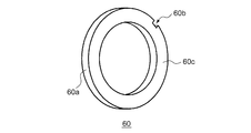
- FIG. 34 is a perspective view of the output plate side brake member 60 according to the fourth embodiment.
- FIG. 35 is a cross-sectional view of the output plate side brake member 60 according to the fourth embodiment.
- the output plate side brake member 60 is an annular member, and the inner diameter and the outer diameter are constant. Further, a groove-like fixing recess 60b parallel to the axial direction is formed on the outer peripheral surface 60a.
- One end surface of the output plate side brake member 60 is a brake surface 60c.
- FIG. 36 (a) is a perspective view of the output plate 64 according to the fourth embodiment
- FIG. 36 (b) is a perspective view of the output plate 64 viewed from a direction different from FIG. 36 (a).
- 37A is a cross-sectional view taken along line AA of the output plate 64 shown in FIG. 36A
- FIG. 37B is a cross-sectional view taken along line BB of the output plate 64 shown in FIG.
- the output plate 64 is a cylindrical member, and the shape of the brake surface is different from that of the output plate 36 according to the first embodiment.
- a through hole 64a into which the gear side shaft 26 is inserted is formed at the center.
- two arc-shaped through-holes 64b are formed around the central portion where the through-holes 64a are formed so that the output pins 46 can be rotated in both directions around the rotation axis with a part of the output pins 46 entering.
- a flat surface of the output plate 64 facing the output plate side brake member 60 is a brake surface 64f. Other shapes are the same as those of the output plate 36.
- the reverse rotation prevention mechanism 130 When an external force is applied to the output shaft 18, the reverse rotation prevention mechanism 130 according to the fourth exemplary embodiment serves as a third frictional force generating unit that generates a brake of the output plate 64 on the brake surface 60 c of the output plate brake material 60. The surface 64f is pressed. This generates a friction braking force that prevents reverse rotation.
- FIG. 38 is an exploded perspective view of the reverse rotation preventing mechanism 140 according to the fifth embodiment.
- FIG. 39 is an enlarged cross-sectional view of the vicinity of the reverse rotation prevention mechanism according to the fifth embodiment.
- the reverse rotation prevention mechanism 140 according to the fifth embodiment differs from the reverse rotation prevention mechanism 130 according to the fourth embodiment in the configuration of the second frictional force generation unit. Specifically, the shapes of the sleeve 66, the lock plate 68, and the lock plate side brake member 70 are different.
- the sleeve 66 is the same as the sleeve 62 according to the fourth embodiment except that the thickness in the axial direction is different.
- the output pin 58 is not provided with the inclined portion 46h that exists in the output pin 46 according to the fourth embodiment.
- FIG. 40 (a) is a perspective view of the lock plate 68 according to the fifth embodiment
- FIG. 40 (b) is a perspective view of the lock plate 68 viewed from a different direction from FIG. 40 (a).
- 41A is a CC cross-sectional view of the lock plate 68 shown in FIG. 40A
- FIG. 41B is a DD cross-sectional view of the lock plate 68 shown in FIG. 40A.
- the lock plate 68 is a cylindrical member, and the shape of the brake surface is different from that of the lock plate 38 according to the first embodiment (fourth embodiment).
- the flat surface of the lock plate 68 that faces the lock plate-side brake material 70 is a brake surface 68f.
- Other shapes are the same as those of the lock plate 38. Therefore, in the reverse rotation prevention mechanism 140 according to the fifth embodiment, even when the output pin 58 rotates, no force is generated that displaces the lock plate 68 in the direction away from the output pin 58.
- FIG. 42 is a perspective view of the lock plate side brake member 70 according to the fifth embodiment.
- FIG. 43 is a cross-sectional view of the lock plate side brake member 70 according to the fifth embodiment.
- the lock plate side brake member 70 is an annular member, and the inner diameter and the outer diameter are constant. Further, a groove-like fixing recess 70b parallel to the axial direction is formed on the outer peripheral surface 70a.
- One end surface of the lock plate side brake member 70 is a brake surface 70c.
- the reverse rotation prevention mechanism 140 When an external force is applied to the output shaft 18, the reverse rotation prevention mechanism 140 according to the fifth embodiment serves as a second frictional force generating part, and the brake plate 70 is braked to the brake surface 70 c of the lock plate side brake material 70. The surface 68f is pressed. This generates a friction braking force that prevents reverse rotation.
- FIG. 44 is an exploded perspective view of the reverse rotation preventing mechanism 150 according to the sixth embodiment.
- FIG. 45 is an enlarged cross-sectional view of the vicinity of the reverse rotation prevention mechanism according to the sixth embodiment.
- the reverse rotation prevention mechanism 150 according to the sixth embodiment is different from the reverse rotation prevention mechanism 100 according to the first embodiment in that there is no third frictional force generation unit. Specifically, the shapes of the gear side shaft 72, the first casing 74, and the output plate 76 are different.
- FIG. 46A is a perspective view of the first casing 74 according to the sixth embodiment
- FIG. 46B is a perspective view of the first casing 74 viewed from a direction different from FIG. 46A.
- FIG. 47 is a cross-sectional view of the first casing 74 according to the sixth embodiment.
- the first casing 74 is formed with a through hole 74a through which the gear side shaft 72 passes, and a cylindrical recess 74b in which the output plate 76, the lock plate 38, and the lock plate side brake material 42 are accommodated.
- a fixing convex portion 74c that fixes the lock plate side brake member 42 so as not to rotate in the concave portion 74b is formed in the inner peripheral portion of the concave portion 74b in parallel with the axial direction of the gear side shaft 72.
- FIG. 48 (a) is a perspective view of an output plate 76 according to the sixth embodiment
- FIG. 48 (b) is a perspective view of the output plate 76 viewed from a direction different from FIG. 48 (a).
- 49A is a cross-sectional view taken along line AA of the output plate 76 shown in FIG. 48A
- FIG. 49B is a cross-sectional view taken along line BB of the output plate 76 shown in FIG.
- the output plate 76 is a cylindrical member, and differs from the output plate 36 according to the first embodiment in that it does not function as a brake surface and the shape of the through hole.
- the output plate 76 is formed with a through hole 76a in the center portion into which the D cut portion 72a at the tip of the gear side shaft 72 is press-fitted.
- the end surface 76b of the output plate 76 on the side where the gear-side shaft 72 is press-fitted is a flat surface. Other shapes are the same as those of the output plate 36.
- FIG. 50 is a schematic diagram for explaining the movement of the reverse rotation preventing mechanism 150 according to the sixth embodiment when an external force is applied to the output shaft.
- the output plate 76 and the gear-side shaft 72 in the reverse rotation prevention mechanism 150 are arranged so that the through-hole 76a and the gear-side shaft 72 are restricted so that the relative movement in the axial direction and the rotational direction with respect to the gear-side shaft 72 is restricted.
- the shape of the D-cut portion 72a that is the tip of the gear-side shaft 72 is defined.
- the reverse rotation preventing mechanism 150 configured as described above cannot move the output plate 76 toward the worm 22 side. Only the lock plate 38 moves to the output pin 46 side. Then, the brake surface 38f (see FIG. 13) of the lock plate 38 is pressed against the brake surface 42c (see FIG. 15) of the lock plate side brake material 42, and a friction braking force is generated. Thereby, the stable inversion resistance can be realized. That is, even when an external force is applied to the output shaft 18, a situation in which the output shaft 18 rotates unintentionally can be prevented.
- the reverse rotation prevention mechanism 150 has a configuration in which the brake surface 38f of the lock plate 38 and the brake surface 42c of the lock plate side brake material 42 are combined as the second frictional force generation unit,
- the brake surface 38f and the brake surface 42c are both tapered surfaces, but are not limited thereto.
- a lock plate 68 having a flat brake surface 68f and a lock plate side brake material 70 having a flat brake surface 70c may be combined as the second frictional force generating portion of the reverse rotation prevention mechanism 150.
- the external force applied to the output shaft acts on the reverse rotation prevention mechanism after being reduced by the worm and the worm wheel.
- the strength of the members constituting the can be reduced.
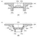
- FIG. 51 is an exploded perspective view of the speed reducer 300 including the reverse rotation preventing mechanism 200 according to the seventh embodiment.
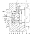
- FIG. 52 is an enlarged cross-sectional view of the reduction gear 300 shown in FIG.
- the reverse rotation prevention mechanism 200 is provided in a torque transmission path between the worm wheel 204 and the output shaft 202 in the speed reducer 300. Accordingly, by causing a part of the function of the reverse rotation prevention mechanism 200 to be assigned to the existing part such as the worm wheel 204, an increase in the number of parts due to the addition of the reverse rotation prevention mechanism 200 can be suppressed.
- the speed reducer 300 includes an output shaft 202, a washer 206, a waterproof O-ring 208, a sintered bearing 210, a casing 212, an O-ring 214 for generating a frictional force, a worm wheel 204, a lock A plate-side brake member 216, a lock plate 218, an output plate 220, a C-type retaining ring 230, an output plate-side brake member 222, and a cover 224 are provided.
- the C-type retaining ring 230 is attached to the groove of the output shaft 202 to prevent the output shaft 202 from coming off the casing 212.
- the C-type retaining ring 230 is disposed so that a gap is formed between the C-type retaining ring 230 and the output plate 220 in a state where the C-type retaining ring 230 is mounted in the groove of the output shaft 202. Thereby, the output plate 220 can move to the cover 224 side.
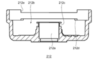
- FIG. 53 is a perspective view of the casing 212 according to the seventh embodiment.
- FIG. 54 is a cross-sectional view of the casing 212 according to the seventh embodiment.
- the casing 212 has a through hole 212a through which the output shaft 202 passes, a cylindrical recess 212b in which the worm wheel 204, the lock plate side brake material 216, the lock plate 218, the output plate 220, and the output plate side brake material 222 are accommodated.
- a second engaging portion 212e that engages so as not to rotate is formed.
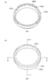
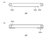
- [Output plate brake material] 55A is a perspective view of the output plate side brake member 222 according to the seventh embodiment
- FIG. 55B is a view of the output plate side brake member 222 viewed from a direction different from FIG. 55A. It is a perspective view.
- 56 (a) is a cross-sectional view taken along the line GG of the output plate side brake member 222 shown in FIG. 55 (b)
- FIG. 56 (b) is a cross-sectional view of the output plate side brake member 222 shown in FIG. It is H sectional drawing.
- the output plate side brake material 222 is an annular member, and an arcuate convex portion 222b is provided on one end surface 222a.
- the output plate side brake material 222 is positioned and fixed with respect to the casing 212 by engaging the second engaging portion 222c, which is a stepped portion at one end of the convex portion 222b, and the second engaging portion 212e of the casing 212.
- the output plate side brake member 222 has a brake surface 222 d that is an inclined surface whose inner diameter changes in the axial direction of the output shaft 202.
- FIG. 57 (a) is a perspective view of the output plate 220 according to the seventh embodiment
- FIG. 57 (b) is a perspective view of the output plate 220 viewed from a different direction from FIG. 57 (a).
- 58 (a) is a cross-sectional view taken along the line II of the output plate 220 shown in FIG. 57 (b)
- FIG. 58 (b) is a cross-sectional view taken along the line JJ of the output plate 220 shown in FIG. 57 (b).
- the output plate 220 is a cylindrical member having a flange, and has a through hole 220a into which the output shaft 202 is inserted, and an opening 220b from which a part of a lock plate 218 described later is exposed. Further, the end face 220d of the output plate 220 on the side facing the lock plate 218 has four arc-shaped inclined portions 220c formed in the circumferential direction around the central portion where the through hole 220a is formed. The inclined portion 220c is configured such that the axial height gradually increases or decreases when the circumferential position changes. In addition, top portions 220e or valley portions 220f are alternately formed between two adjacent inclined portions 220c.
- Each of the two top portions 220e is provided with an arc-shaped convex engaging portion 220g in the axial direction.
- a side surface of the convex engagement portion 220g is an engagement surface 220j that is pressed by a part of a worm wheel 204 described later when the motor is driven.
- the through-hole 220a is configured to restrict relative movement in the rotational direction while allowing movement of the output shaft 202 in the axial direction in a state where the output shaft 202 is inserted.
- the outer peripheral surface of the flange portion 220h of the output plate 220 functions as the brake surface 220i.
- the brake surface 220i according to the present embodiment is a tapered surface.
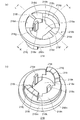
- FIG. 59A is a perspective view of the lock plate 218 according to the seventh embodiment
- FIG. 59B is a perspective view of the lock plate 218 viewed from a direction different from FIG. 59A
- 60A is a KK sectional view of the lock plate 218 shown in FIG. 59A
- FIG. 60B is an LL sectional view of the lock plate 218 shown in FIG. 59A.
- the lock plate 218 is a cylindrical member having a flange, and has an opening 218a at the center. Around the opening 218a, an annular recess 218c is formed which is one step lower than the end face 218b of the lock plate 218 facing the output plate 220.
- the concave portion 218c has four arc-shaped inclined portions 218d formed in the circumferential direction.
- the inclined portion 218d is configured such that the axial height of the output shaft 202 gradually increases or decreases when the circumferential position changes.
- a top portion 218f or a valley portion 218g is formed between two adjacent inclined portions 218d.
- two arc-shaped frictional force applying portions 218e are formed on the inner peripheral portion of the opening 218a with the opening 218a interposed therebetween.
- the frictional force applying unit 218e is exposed from the opening 220b of the output plate 220 and generates a frictional force by contacting the O-ring 214.
- an inclined portion 218i constituting a separation mechanism for separating the lock plate 218 from the lock plate side brake member 216 is formed on the end surface 218h of the lock plate 218 facing the worm wheel 204.
- the inclined portion 218i is formed on the upper surface of the arc-shaped convex portion 218j.
- the side surface of the arc-shaped convex portion 218j is an engagement surface 218k that is pushed by a part of a worm wheel 204 described later when the motor is driven.
- the outer peripheral surface of the flange portion 218m of the lock plate 218 functions as the brake surface 218n.
- the brake surface 218n according to the present embodiment is a tapered surface.
- FIG. 61A is a perspective view of the lock plate side brake member 216 according to the seventh embodiment
- FIG. 61B is a view of the lock plate side brake member 216 viewed from a different direction from FIG. 61A. It is a perspective view.
- 62A is a cross-sectional view taken along line MM of the lock plate side brake member 216 shown in FIG. 61B
- FIG. 62B is an N— view of the lock plate side brake member 216 shown in FIG. 61B. It is N sectional drawing.
- the lock plate side brake member 216 is an annular member, and an arcuate convex portion 216b is provided on one end surface 216a.
- the lock plate side brake material 216 is positioned and fixed with respect to the casing 212 by engaging the first engaging portion 216c, which is a stepped portion at one end of the convex portion 216b, and the first engaging portion 212d of the casing 212.
- the Moreover, the lock plate side brake material 216 has a brake surface 216d that is an inclined surface whose inner diameter changes in the axial direction.
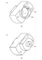
- FIG. 63 is a perspective view of a worm wheel 204 according to the seventh embodiment.
- 64A is an OO cross-sectional view of the worm wheel 204 shown in FIG. 63
- FIG. 64B is a PP cross-sectional view of the worm wheel 204 shown in FIG.
- the worm wheel 204 is a cylindrical member, and a gear portion 204a is formed on the outer peripheral surface.
- a cylindrical portion 204b into which the shaft portion of the casing 212 is inserted is formed at the center of the worm wheel 204.
- the cylindrical portion 204b is formed with a notch portion 204i into which the frictional force applying portion 218e of the lock plate 218 enters.
- the outer peripheral portion of the cylindrical portion 204b is an annular concave portion 204c, and two convex engaging portions 204d are provided so as to protrude in the axial direction.
- the convex engagement portion 204d When the motor is driven, the convex engagement portion 204d has an engagement surface 204e (inner diameter side) that engages with the engagement surface 220j of the output plate 220 and the engagement surface 218k of the lock plate 218, and the engagement surface 204f ( Outer diameter side).
- each arc-shaped inclined portion 204g formed in the circumferential direction is formed in the circumferential direction.
- the inclined portion 204g is configured such that the axial height gradually increases or decreases when the circumferential position changes.
- convex engaging portions 204d or valley portions 204h are alternately formed between two adjacent inclined portions 204g.
- FIG. 65 is an exploded perspective view of a main part of the reverse rotation preventing mechanism 200 according to the seventh embodiment.
- FIG. 66 is a schematic diagram for explaining the movement of each component when an external force is applied to the output shaft.
- FIG. 66 schematically shows a developed sectional view of the inner diameter side and the outer diameter side of the reverse rotation prevention mechanism of FIG.
- the output plate 220 and the output shaft 202 in the reverse rotation preventing mechanism 200 according to the seventh embodiment are relatively relative to each other in the rotational direction while allowing the output plate 220 to move relative to the output shaft 202 in the axial direction.
- the shapes of the through holes 220a and the tips of the output shafts 202 are determined so that the movement is limited (relative rotation does not occur).
- the output plate 220 moves toward the output plate side brake member 222, and the lock plate 218. Will move toward the lock plate side brake material 216.
- the brake surface 220i of the output plate 220 is pressed against the brake surface 222d of the output plate side brake material 222 to generate a friction braking force
- the brake surface 218n of the lock plate 218 is the brake surface 216d of the lock plate side brake material 216.
- the stable inversion resistance can be realized. That is, even when an external force is applied to the output shaft 202, a situation in which the output shaft 202 rotates unintentionally can be prevented.
- FIG. 67 is a schematic diagram for explaining the operation when the motor is driven in the direction in which the worm wheel rotates counterclockwise (CCW) from the state in which the reverse rotation prevention mechanism shown in FIG. 66 functions.
- FIG. 68 is a schematic diagram for explaining the operation when the motor is driven in the direction in which the worm wheel rotates clockwise (CW) from the state in which the reverse rotation prevention mechanism shown in FIG. 66 functions.
- the convex engagement portion 204d of the worm wheel 204 engages with the convex portion 218j of the lock plate 218, and not only the output plate 220 but also the lock plate 218 starts to rotate with the worm wheel 204 (STEP_F ). That is, since the lock plate 218 and the output plate 220 rotate at the same time in a state where no force is generated at the inclined portions, the output plate 220 rotates in a state where no braking force is generated. As a result, the rotation of the worm wheel 204 is transmitted to the output shaft 202.
- the reverse rotation preventing mechanism 200 uses the friction braking force generated when an external force is applied to the output shaft 202 in the case of normal motor drive. It is possible to suppress the decrease in motor torque transmission efficiency due to frictional resistance.
- the O-ring 214 is attached to the annular groove 212c of the casing 212, and the frictional force applying portion 218e of the lock plate 218 is brought into contact with the O-ring 214 ( (See FIG. 52 and the like).
- the force that tries to stay at the position of the lock plate 218 due to the frictional resistance between the friction force applying portion 218e and the O-ring 40 works, and the lock plate 218 is rotated even if the output plate 220 rotates. Is prevented.
- the frictional resistance between the members is appropriately set in consideration of cogging torque, gear part frictional resistance, shaft frictional resistance, and the like.
- FIG. 69 is an exploded perspective view of the speed reducer 310 including the reverse rotation prevention mechanism 250 according to the eighth embodiment.
- 70 is an enlarged cross-sectional view of the speed reducer 310 shown in FIG.
- the reverse rotation prevention mechanism 250 according to the eighth embodiment is different from the reverse rotation prevention mechanism 200 according to the seventh embodiment in that there is no third frictional force generating part. Specifically, the shapes of the output shaft 203, the casing 226, and the output plate 228 are different. Further, there is no output plate side brake material used in the reverse rotation prevention mechanism 200.
- the output shaft 203 has a groove for mounting the C-type retaining ring 230 at the end portion on the side inserted into the output plate 228, slightly compared to the output shaft 202 (see the seventh embodiment). Except for being provided on the 228 side, it is the same as the output shaft 202.
- the casing 226 is different from the casing 212 according to the seventh embodiment in that there is no second engagement portion 212e of the casing 212 due to the absence of the output plate side brake material. That is, the casing 226 is only slightly different in the shape of the opening edge on the cover side.
- the output plate 228 is different from the output plate 220 according to the seventh embodiment in that there is no flange portion 220h having the brake surface 220i.
- the end of the output shaft 203 is fixed to the output plate 228 by a C-type retaining ring 230, so that the lock plate 218 cannot move in the axial direction on the cover 224 side with respect to the output shaft 203.
- the output plate 228 cannot move to the cover 224 side, and only the lock plate 218 is the lock plate. It moves to the side brake material 216 side. Then, the brake surface 218n of the lock plate 218 is pressed against the brake surface 216d of the lock plate side brake member 216, and a friction braking force is generated.
- the present invention has been described with reference to the above-described embodiments.
- the present invention is not limited to the above-described embodiments, and the configurations of the embodiments are appropriately combined or replaced. Those are also included in the present invention. Further, it is possible to appropriately change the combination and processing order in each embodiment based on the knowledge of those skilled in the art and to add various modifications such as various design changes to each embodiment. Embodiments to which is added can also be included in the scope of the present invention.
- the present invention can be used for, for example, a motor used to open and close a vehicle power window and a sunroof.
Landscapes
- Engineering & Computer Science (AREA)
- General Engineering & Computer Science (AREA)
- Mechanical Engineering (AREA)
- Braking Arrangements (AREA)
- Power-Operated Mechanisms For Wings (AREA)
- Connection Of Motors, Electrical Generators, Mechanical Devices, And The Like (AREA)
- Gear Transmission (AREA)
Abstract
L'invention concerne un mécanisme anti-retour (100) disposé dans un trajet de transmission de couple entre un arbre de sortie et un arbre d'entraînement de moteur. De plus, le mécanisme anti-retour (100) comprend : une première unité de génération de frottement qui est configurée de manière à commander une rotation relative d'une plaque de verrouillage (38) disposée dans le trajet de transmission de couple par rapport à d'autres éléments lorsqu'une force externe est appliquée à l'arbre de sortie ; et une seconde unité de génération de frottement qui est configurée de manière à générer une force de freinage pour empêcher toute rotation en sens inverse par une partie de la plaque de verrouillage (38) qui est pressée lorsqu'une force externe est appliquée à l'arbre de sortie. La première unité de génération de frottement est disposée dans une région différente de la seconde unité de génération de frottement.
Priority Applications (4)
| Application Number | Priority Date | Filing Date | Title |
|---|---|---|---|
| CN201680011329.5A CN107407124B (zh) | 2015-02-23 | 2016-02-12 | 逆转防止机构和带减速机的电机 |
| DE112016000861.9T DE112016000861T5 (de) | 2015-02-23 | 2016-02-12 | Rückwärtsdrehungsverhinderungsmechanismus und Motor mit Untersetzungsgetriebe |
| MX2017010733A MX2017010733A (es) | 2015-02-23 | 2016-02-12 | Mecanismo antiretorno y motor con reductor de velocidad. |
| US15/683,323 US10731398B2 (en) | 2015-02-23 | 2017-08-22 | Reverse rotation prevention mechanism and motor with reducer |
Applications Claiming Priority (2)
| Application Number | Priority Date | Filing Date | Title |
|---|---|---|---|
| JP2015-033202 | 2015-02-23 | ||
| JP2015033202A JP6257543B2 (ja) | 2015-02-23 | 2015-02-23 | 逆転防止機構および減速機付モータ |
Related Child Applications (1)
| Application Number | Title | Priority Date | Filing Date |
|---|---|---|---|
| US15/683,323 Continuation US10731398B2 (en) | 2015-02-23 | 2017-08-22 | Reverse rotation prevention mechanism and motor with reducer |
Publications (1)
| Publication Number | Publication Date |
|---|---|
| WO2016136490A1 true WO2016136490A1 (fr) | 2016-09-01 |
Family
ID=56788455
Family Applications (1)
| Application Number | Title | Priority Date | Filing Date |
|---|---|---|---|
| PCT/JP2016/054071 Ceased WO2016136490A1 (fr) | 2015-02-23 | 2016-02-12 | Mécanisme anti-retour et moteur comprenant un réducteur de vitesse |
Country Status (6)
| Country | Link |
|---|---|
| US (1) | US10731398B2 (fr) |
| JP (1) | JP6257543B2 (fr) |
| CN (1) | CN107407124B (fr) |
| DE (1) | DE112016000861T5 (fr) |
| MX (1) | MX2017010733A (fr) |
| WO (1) | WO2016136490A1 (fr) |
Families Citing this family (6)
| Publication number | Priority date | Publication date | Assignee | Title |
|---|---|---|---|---|
| JP6257543B2 (ja) | 2015-02-23 | 2018-01-10 | マブチモーター株式会社 | 逆転防止機構および減速機付モータ |
| CN107923491A (zh) * | 2016-07-25 | 2018-04-17 | 马渊马达株式会社 | 防止逆转机构和带减速机的电机 |
| CN106761136B (zh) * | 2016-12-27 | 2018-04-20 | 青岛海尔股份有限公司 | 自动开门装置及具有该装置的冰箱 |
| CN111595774B (zh) * | 2020-07-08 | 2021-03-30 | 北京航空航天大学 | 一种防逆转机构摩擦性能试验工装 |
| FR3120345B1 (fr) * | 2021-03-04 | 2024-05-24 | Autoliv Dev | Volant de vehicule automobile a jante escamotable avec limiteur de couple |
| CN114194163A (zh) * | 2021-10-29 | 2022-03-18 | 浙江诸暨万宝机械有限公司 | 一种具有单电机配单涡轮的mgu驱动单活塞的电子驻车系统 |
Citations (4)
| Publication number | Priority date | Publication date | Assignee | Title |
|---|---|---|---|---|
| JPS6136476A (ja) * | 1983-09-28 | 1986-02-21 | 株式会社デンソー | 減速機付電動機 |
| JPH08242551A (ja) * | 1995-03-01 | 1996-09-17 | Jidosha Denki Kogyo Co Ltd | 小型モータ |
| JP2005110449A (ja) * | 2003-10-01 | 2005-04-21 | Mitsuba Corp | 減速機構付き電動モータ |
| WO2011145388A1 (fr) * | 2010-05-19 | 2011-11-24 | アイシン精機株式会社 | Embrayage autobloquant |
Family Cites Families (25)
| Publication number | Priority date | Publication date | Assignee | Title |
|---|---|---|---|---|
| GB321637A (en) * | 1928-08-03 | 1929-11-04 | Edward Henry James Cecil Gille | Improvements in or relating to friction clutches for the transmission of power |
| JPS4843667Y1 (fr) * | 1970-01-22 | 1973-12-17 | ||
| DE3420190A1 (de) | 1984-05-30 | 1985-12-05 | Arthur Pfeiffer Vakuumtechnik Wetzlar Gmbh, 6334 Asslar | Oelgedichtete rotationsvakuumpumpe |
| ES2078571T3 (es) * | 1991-04-18 | 1995-12-16 | Siemens Ag | Accionamiento por motor con engranaje en vehiculos motorizados. |
| JP3469276B2 (ja) | 1993-08-30 | 2003-11-25 | アスモ株式会社 | 逆転防止軸受装置 |
| US5605071A (en) * | 1995-06-06 | 1997-02-25 | Itt Automotive Electrical Systems, Inc. | Enveloped worm gear clutch wedgelock responsive to reaction force |
| KR100596557B1 (ko) * | 1998-08-03 | 2006-07-04 | 아스모 가부시키가이샤 | 모터 및 감속기구를 구비한 구동장치 |
| US6450056B2 (en) | 2000-02-02 | 2002-09-17 | Asmo Co., Ltd. | Motor having speed reduction device |
| US20030000325A1 (en) * | 2001-06-28 | 2003-01-02 | Hoehn Richard T. | Multi-speed worm gear reduction assembly |
| JP4211421B2 (ja) * | 2003-02-07 | 2009-01-21 | 株式会社ジェイテクト | クラッチ装置 |
| US6814209B1 (en) * | 2003-05-29 | 2004-11-09 | Siemens Vdo Automotive Corporation | Inertia clutch mechanism in motors to prevent backdrive |
| JP4408410B2 (ja) * | 2004-11-26 | 2010-02-03 | アスモ株式会社 | モータ装置及びワイパ装置 |
| JP2007040424A (ja) | 2005-08-03 | 2007-02-15 | Ntn Corp | 電動リニアアクチュエータ |
| JP5147209B2 (ja) | 2005-09-30 | 2013-02-20 | キヤノン株式会社 | 駆動伝達装置及び画像形成装置 |
| JP4850606B2 (ja) * | 2006-07-27 | 2012-01-11 | アスモ株式会社 | モータ及びワイパ装置 |
| CN101162037B (zh) * | 2006-10-11 | 2011-08-03 | 德昌电机股份有限公司 | 蜗轮传动机构 |
| ATE497866T1 (de) * | 2006-12-07 | 2011-02-15 | Panasonic Corp | Gelenkmechanismus |
| JP2010048353A (ja) | 2008-08-22 | 2010-03-04 | Mitsuba Corp | クラッチ機構、クラッチ付減速機、および減速機付モータ |
| US8826592B2 (en) * | 2009-09-29 | 2014-09-09 | Aisin Seiki Kabushiki Kaisha | Window regulator device |
| DE102009055412A1 (de) * | 2009-12-30 | 2011-07-07 | Robert Bosch GmbH, 70469 | Verstellantrieb mit integrierten Zusatzfunktionen |
| CA2751959C (fr) * | 2010-09-24 | 2018-08-21 | Deere & Company | Boite de vitesse d'entrainement en cercle a multiples vis sans fin |
| CN104507695B (zh) | 2012-11-30 | 2017-09-01 | 日本电产三协株式会社 | 墨带支座和印刷装置 |
| JP5978235B2 (ja) | 2014-01-28 | 2016-08-24 | 京セラドキュメントソリューションズ株式会社 | 定着装置及び画像形成装置 |
| JP6390954B2 (ja) | 2014-09-29 | 2018-09-19 | 株式会社リコー | 駆動伝達装置、駆動装置および画像形成装置 |
| JP6257543B2 (ja) | 2015-02-23 | 2018-01-10 | マブチモーター株式会社 | 逆転防止機構および減速機付モータ |
-
2015
- 2015-02-23 JP JP2015033202A patent/JP6257543B2/ja active Active
-
2016
- 2016-02-12 MX MX2017010733A patent/MX2017010733A/es unknown
- 2016-02-12 WO PCT/JP2016/054071 patent/WO2016136490A1/fr not_active Ceased
- 2016-02-12 CN CN201680011329.5A patent/CN107407124B/zh active Active
- 2016-02-12 DE DE112016000861.9T patent/DE112016000861T5/de not_active Withdrawn
-
2017
- 2017-08-22 US US15/683,323 patent/US10731398B2/en active Active
Patent Citations (4)
| Publication number | Priority date | Publication date | Assignee | Title |
|---|---|---|---|---|
| JPS6136476A (ja) * | 1983-09-28 | 1986-02-21 | 株式会社デンソー | 減速機付電動機 |
| JPH08242551A (ja) * | 1995-03-01 | 1996-09-17 | Jidosha Denki Kogyo Co Ltd | 小型モータ |
| JP2005110449A (ja) * | 2003-10-01 | 2005-04-21 | Mitsuba Corp | 減速機構付き電動モータ |
| WO2011145388A1 (fr) * | 2010-05-19 | 2011-11-24 | アイシン精機株式会社 | Embrayage autobloquant |
Also Published As
| Publication number | Publication date |
|---|---|
| US20170350182A1 (en) | 2017-12-07 |
| JP2016156153A (ja) | 2016-09-01 |
| DE112016000861T5 (de) | 2017-11-16 |
| US10731398B2 (en) | 2020-08-04 |
| JP6257543B2 (ja) | 2018-01-10 |
| MX2017010733A (es) | 2018-03-21 |
| CN107407124B (zh) | 2019-11-05 |
| CN107407124A (zh) | 2017-11-28 |
Similar Documents
| Publication | Publication Date | Title |
|---|---|---|
| JP6257543B2 (ja) | 逆転防止機構および減速機付モータ | |
| WO2020054763A1 (fr) | Moteur électrique doté d'un embrayage de coupure à entrée inverse | |
| JP2016133126A (ja) | 電動式直動アクチュエータおよび電動式ブレーキ装置 | |
| JP4845167B2 (ja) | ギヤボックスの同期装置用組立体システム | |
| US3270843A (en) | Synchronizer clutch assembly | |
| CN105889352B (zh) | 传动器、有传动器、传动轴和传动齿轮的组件及传动装置 | |
| US9188169B2 (en) | Shift device with synchronizer | |
| JP6333872B2 (ja) | 車両用シールリング | |
| JP2015190549A (ja) | 手動変速機の同期装置 | |
| KR20060008966A (ko) | 백 드라이브를 방지하기 위한 전기 모터용 클러치 조립체 | |
| WO2018020554A1 (fr) | Mécanisme de prévention de rotation inverse et moteur à réducteur de vitesse | |
| JP2002130336A (ja) | 電動機ユニット | |
| JP4513158B2 (ja) | 摩擦ローラ式変速機 | |
| JP2018121506A (ja) | 逆転防止機構および減速機付モータ | |
| JP2001107988A (ja) | クラッチ装置 | |
| JP5149763B2 (ja) | 過大トルクリリース機構を有する歯車組立体及びそれを備える減速機 | |
| JP2008309188A (ja) | 2ウェイクラッチユニット | |
| JP4337725B2 (ja) | 中間歯車付スタータ | |
| KR100482112B1 (ko) | 수동변속기의 동기장치 | |
| JP2007120633A (ja) | 捩り振動低減装置 | |
| JP4987337B2 (ja) | クラッチユニット | |
| JP2001165202A (ja) | カム機構とこれを用いたクラッチ装置 | |
| JP7213148B2 (ja) | クラッチ機構及びモータ装置 | |
| JP2010025293A (ja) | 車両用手動変速機の同期かみあい装置 | |
| JP2017133599A (ja) | 逆入力防止クラッチ |
Legal Events
| Date | Code | Title | Description |
|---|---|---|---|
| 121 | Ep: the epo has been informed by wipo that ep was designated in this application |
Ref document number: 16755237 Country of ref document: EP Kind code of ref document: A1 |
|
| WWE | Wipo information: entry into national phase |
Ref document number: MX/A/2017/010733 Country of ref document: MX |
|
| WWE | Wipo information: entry into national phase |
Ref document number: 112016000861 Country of ref document: DE |
|
| 122 | Ep: pct application non-entry in european phase |
Ref document number: 16755237 Country of ref document: EP Kind code of ref document: A1 |