WO2016136979A1 - Dispositif à cycle frigorifique - Google Patents
Dispositif à cycle frigorifique Download PDFInfo
- Publication number
- WO2016136979A1 WO2016136979A1 PCT/JP2016/055914 JP2016055914W WO2016136979A1 WO 2016136979 A1 WO2016136979 A1 WO 2016136979A1 JP 2016055914 W JP2016055914 W JP 2016055914W WO 2016136979 A1 WO2016136979 A1 WO 2016136979A1
- Authority
- WO
- WIPO (PCT)
- Prior art keywords
- refrigeration cycle
- compressor
- control unit
- high pressure
- value
- Prior art date
- Legal status (The legal status is an assumption and is not a legal conclusion. Google has not performed a legal analysis and makes no representation as to the accuracy of the status listed.)
- Ceased
Links
Images



Classifications
-
- F—MECHANICAL ENGINEERING; LIGHTING; HEATING; WEAPONS; BLASTING
- F25—REFRIGERATION OR COOLING; COMBINED HEATING AND REFRIGERATION SYSTEMS; HEAT PUMP SYSTEMS; MANUFACTURE OR STORAGE OF ICE; LIQUEFACTION SOLIDIFICATION OF GASES
- F25B—REFRIGERATION MACHINES, PLANTS OR SYSTEMS; COMBINED HEATING AND REFRIGERATION SYSTEMS; HEAT PUMP SYSTEMS
- F25B49/00—Arrangement or mounting of control or safety devices
- F25B49/02—Arrangement or mounting of control or safety devices for compression type machines, plants or systems
-
- F—MECHANICAL ENGINEERING; LIGHTING; HEATING; WEAPONS; BLASTING
- F24—HEATING; RANGES; VENTILATING
- F24F—AIR-CONDITIONING; AIR-HUMIDIFICATION; VENTILATION; USE OF AIR CURRENTS FOR SCREENING
- F24F11/00—Control or safety arrangements
- F24F11/89—Arrangement or mounting of control or safety devices
-
- F—MECHANICAL ENGINEERING; LIGHTING; HEATING; WEAPONS; BLASTING
- F25—REFRIGERATION OR COOLING; COMBINED HEATING AND REFRIGERATION SYSTEMS; HEAT PUMP SYSTEMS; MANUFACTURE OR STORAGE OF ICE; LIQUEFACTION SOLIDIFICATION OF GASES
- F25B—REFRIGERATION MACHINES, PLANTS OR SYSTEMS; COMBINED HEATING AND REFRIGERATION SYSTEMS; HEAT PUMP SYSTEMS
- F25B1/00—Compression machines, plants or systems with non-reversible cycle
-
- F—MECHANICAL ENGINEERING; LIGHTING; HEATING; WEAPONS; BLASTING
- F25—REFRIGERATION OR COOLING; COMBINED HEATING AND REFRIGERATION SYSTEMS; HEAT PUMP SYSTEMS; MANUFACTURE OR STORAGE OF ICE; LIQUEFACTION SOLIDIFICATION OF GASES
- F25B—REFRIGERATION MACHINES, PLANTS OR SYSTEMS; COMBINED HEATING AND REFRIGERATION SYSTEMS; HEAT PUMP SYSTEMS
- F25B13/00—Compression machines, plants or systems, with reversible cycle
Definitions
- Embodiment of this invention is related with the refrigerating-cycle apparatus which coped with the raise of the high-pressure side pressure.
- a refrigeration cycle device mounted on an air conditioner or the like has a high pressure switch that responds to the high pressure side pressure of the refrigeration cycle, stops the compressor when the high pressure side pressure rises and the high pressure switch is activated, and then the high pressure switch The compressor is restarted when the side pressure drops and the high pressure switch returns. By stopping the compressor when the high-pressure switch is activated, an abnormal increase in the high-pressure side pressure is prevented and the safety of the refrigeration cycle equipment including the compressor is ensured.
- the transition to the R32 refrigerant excellent in capacity and energy efficiency is progressing.
- the pressure when the R32 refrigerant is discharged from the compressor is higher than that of the R410A refrigerant, the high pressure switch is easily operated.
- An object of an embodiment of the present invention is to provide a refrigeration cycle apparatus that can suppress an increase in the high-pressure side pressure after the compressor is restarted, thereby avoiding frequent repetition of stop and restart of the compressor. That is.
- the refrigeration cycle apparatus includes a refrigeration cycle including a compressor, a condenser, an expansion valve, and an evaporator, a high-pressure switch that responds to a high-pressure side pressure of the refrigeration cycle, and control means.
- the control means stops the compressor in response to the operation of the high pressure switch, and then restarts the compressor in response to the return of the high pressure switch, and performs opening degree control on the expansion valve upon the restart. Shift the lower limit value to the increasing side.
- FIG. 1 is a block diagram illustrating a configuration of an embodiment.
- FIG. 2 is a flowchart illustrating the control according to the embodiment.
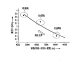
- FIG. 3 is a diagram illustrating the relationship between the volume of the refrigeration cycle during cooling and the high-pressure side pressure in one embodiment.
- FIG. 4 is a diagram illustrating the relationship between the volume of the refrigeration cycle during heating and the high-pressure side pressure in one embodiment.
- FIG. 5 is a diagram illustrating an example of changes in the high-pressure side pressure, the expansion valve opening degree, the discharge refrigerant temperature, and the compressor rotation speed in one embodiment.
- one end of an outdoor heat exchanger 3 is connected to a discharge port of the compressor 1 via a four-way valve 2.
- One end of a plurality of indoor heat exchangers 5a, 5b, ... 5n is connected to the other end of the outdoor heat exchanger 3 via a plurality of expansion valves 4a, 4b, ... 4n, and the indoor heat exchangers 5a, 5b are connected.
- ,... 5n are connected to the suction port of the compressor 1 through the four-way valve 2 by piping.
- a heat pump refrigeration cycle is constituted by these pipe connections. This heat pump refrigeration cycle is filled with a refrigerant containing, for example, 50% or more of an R32 refrigerant.
- the refrigerant discharged from the compressor 1 passes through the four-way valve 2, the outdoor heat exchanger (condenser) 3, the expansion valves 4a, 4b,.
- the refrigerant flowing into the evaporators 5a, 5b,... 5n and flowing out of the indoor heat exchangers 5a, 5b,... 5n is sucked into the compressor 1 through the four-way valve 2.
- the refrigerant discharged from the compressor 1 flows to the indoor heat exchangers (condensers) 5a, 5b,.
- the refrigerant flowing out from the indoor heat exchangers 5a, 5b,... 5n is sucked into the compressor 1 through the expansion valves 4a, 4b,... 4n, the outdoor heat exchanger (evaporator) 3, and the four-way valve 2.
- the outdoor fan 6 is disposed in the vicinity of the outdoor heat exchanger 3, and the indoor fans 7a, 7b,... 7n are disposed in the vicinity of the indoor heat exchangers 5a, 5b,.
- An inverter 8 is connected to the motor of the compressor 1.
- the inverter 8 converts the voltage of the AC power source 9 into DC, converts the DC voltage into an AC voltage having a predetermined frequency F, and outputs the AC voltage.
- the motor of the compressor 1 operates at a rotational speed corresponding to the output frequency F.
- a high pressure switch 11 and a refrigerant temperature sensor 12 are attached to the high pressure side pipe between the discharge port of the compressor 1 and the four-way valve 2.
- the high pressure switch 11 is activated when the pressure (referred to as high pressure side pressure) Pd of the refrigerant discharged from the compressor 1 rises to a set value Pd2 or more, and the high pressure side pressure Pd drops below the set value Pd1 ( ⁇ Pd2). If this happens, return.
- the refrigerant temperature sensor 12 detects the temperature Td of the refrigerant discharged from the compressor 1.
- the expansion valves 4a, 4b,..., 4n are so-called pulse motor valves whose opening degree changes continuously according to the number of pulses of the input drive pulse signal.
- a compressor 1, a four-way valve 2, an outdoor heat exchanger 3, expansion valves 4a, 4b, ... 4n, an outdoor fan 6, and an inverter 8 are mounted in the outdoor unit A.
- the indoor heat exchangers 5a, 5b, ... 5n and the indoor fans 7a, 7b, ... 7n are mounted on the plurality of indoor units Ba, Bb, ... Bn, respectively.
- a control unit 20 is connected to the outdoor unit A and the indoor units Ba, Bb,... Bn.
- the control unit 20 includes a microcomputer and its peripheral circuits, and includes a first control unit 20a, a second control unit 20b, and a third control unit 20c as main functions.
- the first control unit 20 a stops the compressor 1 according to the operation of the high pressure switch 11, and then restarts the compressor 1 according to the return of the high pressure switch 11.
- the second control unit 20b expands the expansion valve 4a so that the degree of superheat (cooling) and the degree of supercooling (heating) of the indoor heat exchangers 5a, 5b,. , 4b,..., 4n are controlled within a range between a predetermined upper limit value Qmax and a predetermined lower limit value Qmin.
- the third control unit 20c shifts the lower limit value Qmin of the opening control for the expansion valves 4a, 4b,. Restrict.
- the second control unit 20b sets the predetermined value ⁇ Q, which is the shift amount, to a different value ( ⁇ Q1, ⁇ Q2,... ⁇ Qn) depending on the volume of the heat pump refrigeration cycle (the number of indoor units Ba, Bb,. Set. Specifically, the second control unit 20b sets the predetermined value ⁇ Q to a value proportional to the volume of the heat pump refrigeration cycle during cooling, and to a value inversely proportional to the volume of the heat pump refrigeration cycle during heating. . Further, the second control unit 20b selectively executes the opening degree throttle restriction that shifts the lower limit value Qmin by comparing the discharge refrigerant temperature Td detected by the refrigerant temperature sensor 12 with the set value Tds. Furthermore, the 2nd control part 20b cancels
- step S1 the control unit 20 starts the compressor 1 (step S2). With this activation, the control unit 20 checks whether or not the opening limit flag f is “0” (step S3).
- the control unit 20 When the opening degree restriction flag f is “0” (YES in step S3), the control unit 20 has a constant degree of superheat (during cooling) and degree of supercooling (during heating) of the indoor heat exchangers 5a, 5b,.
- the opening Q of the expansion valves 4a, 4b,..., 4n is controlled within a range between a predetermined upper limit value Qmax and a predetermined lower limit value Qmin (step S4).
- the control unit 20 monitors the operation of the high pressure switch 11 along with the opening degree control (step S7). When the high voltage switch 11 is not activated (NO in step S7), the control unit 20 monitors the operation stop of the indoor units Ba, Bb,... Bn (step S14).
- step S14 If it is not necessary to stop the indoor units Ba, Bb,... Bn (NO in step S14), the control unit 20 returns to the flag determination in step S3.
- the control unit 20 stops the compressor 1 (step S15). And the control part 20 resets the opening degree restriction flag f to "0" (step S16), and returns to the driving
- step S7 when the high voltage switch 11 is activated (YES in step S7), the control unit 20 stops the compressor 1 (step S8). This stop prevents an abnormal increase in the high-pressure side pressure. And the control part 20 starts the time count t (step S9), and monitors the reset of the high voltage
- step S11 If the time count t has not reached the predetermined time ts (NO in step S11), the control unit 20 continues the time count t (step S9). If the time count t has reached the predetermined time ts (YES in step S11), the control unit 20 restarts the compressor 1 (step S12), and sets the opening restriction flag f to “1” (step S12). Step S13). And the control part 20 monitors the operation stop of indoor unit Ba, Bb, ... Bn (step S14).
- control unit 20 If it is not necessary to stop the indoor units Ba, Bb,... Bn (NO in step S14), the control unit 20 returns to the flag determination in step S3. At this time, since the opening degree control flag f is “1” (NO in step S3), the control unit 20 compares the discharge refrigerant temperature (detected temperature) Td detected by the refrigerant temperature sensor 12 with the set value Tds ( Step S5).
- the control unit 20 controls the opening Q of the expansion valves 4a, 4b,... 4n within the range between the upper limit value Qmax and the normal lower limit value Qmin. (Step S4).
- Step S5 When the discharge refrigerant temperature Td is equal to or higher than the set value Tds (YES in Step S5), the control unit 20 shifts the lower limit value Qmin of the opening degree control to the increase side by a predetermined value ⁇ Q, The opening Q of the expansion valves 4a, 4b,..., 4n is controlled within the range of “” (step S6).
- the relationship between the outside air temperature and the high pressure side pressure Pd and the relationship between the outside air temperature and the discharge refrigerant temperature Td are proportional to each other.
- the high-pressure side pressure Pd and the discharge refrigerant temperature Td also rise.
- the opening degree Q of the expansion valves 4a, 4b,..., 4n is reduced to the lower limit value Qmin, the high pressure switch 11 is activated before the compressor 1 restarts, and the compressor 1 May lead to a stop.
- the throttle opening restriction that shifts the lower limit value Qmin of the opening degree control to the increase side is executed, so that after the compressor 1 is restarted.
- An increase in the high pressure side pressure Pd can be suppressed.
- the high-pressure side pressure Pd is increased after the compressor 1 is restarted by restricting the opening degree as in the case of the R410A refrigerant. Can be suppressed.
- the operation of the high-pressure switch 11 when the compressor 1 is restarted can be prevented, and as a result, frequent stop and restart of the compressor 1 can be prevented.
- the indoor temperature which is a load can be stabilized and the comfort of air conditioning improves.
- step S5 when the discharged refrigerant temperature Td is lower than the set value Tds (NO in step S5), the control unit 20 does not perform the restriction on the opening degree, and the range between the upper limit value Qmax and the normal lower limit value Qmin. To control the opening Q (step S4).
- the high-pressure side pressure Pd changes according to the volume of the heat pump refrigeration cycle (the number of indoor units Ba, Bb,... Bn). That is, during cooling, as shown in FIG. 3, the higher the volume, the higher the high pressure side pressure Pd. Conversely, during heating, as shown in FIG. 4, the smaller the volume, the higher the high pressure side pressure Pd.
- the control unit 20 changes the predetermined value ⁇ Q, which is the shift amount of the aperture restriction, to a different value ( ⁇ Q1, ⁇ Q2,... ⁇ Qn) depending on the number of indoor units Ba, Bb,. Set. That is, at the time of cooling, considering that the high pressure side pressure Pd increases as the number of operating units increases, the control unit 20 sets a predetermined value ⁇ Q1 when the number of operating units is 1, and the number of operating units is 2 units. Sets a predetermined value ⁇ Q2 (> Q1), sets a predetermined value ⁇ Q3 (> Q2) when the number of operating units is 3, and sets a predetermined value ⁇ Qn (...> Q3) when the number of operating units is the largest n Set.
- ⁇ Q is the shift amount of the aperture restriction
- the control unit 20 sets a predetermined value ⁇ Qn when the number of operating units is 1, and sets the predetermined value ⁇ Q3 as the operating number increases. ⁇ Q2 and ⁇ Q1 are sequentially set. In short, the predetermined value ⁇ Q is increased on the side where the increase in the high-pressure side pressure Pd is significant.
- control unit 20 switches the set value Tds, which is a reference for selective execution of the aperture restriction, in accordance with the switching of the predetermined values ⁇ Q1, ⁇ Q2,... ⁇ Qn. That is, the control unit 20 selects the setting value Tds1 when setting the predetermined value ⁇ Q1, selects the setting value Tds2 (> Tds1) when setting the predetermined value ⁇ Q2, and sets the setting value Tds3 (when setting the predetermined value ⁇ Q3. > Tds2) is selected, and when the predetermined value ⁇ Qn is set, the set value Tdsn (...> Tds3) is selected.
- the predetermined value ⁇ Q which is the amount of shift of the aperture restriction, is set to a different value depending on the number of indoor units Ba, Bb,.
- the frequency of the compressor 1 is increased regardless of changes in the number of indoor units Ba, Bb,... Bn, that is, regardless of changes in the volume of the heat pump refrigeration cycle. Can be prevented from repeatedly stopping and restarting.
- FIG. 5 shows an example of changes in the high-pressure side pressure Pd, the expansion valve opening Q, the discharge refrigerant temperature Td, and the compressor rotational speed.
- the opening degree Q is reduced, the high pressure side pressure Pd increases.
- the high pressure switch 11 is activated and the compressor 1 is stopped.
- the high pressure switch 11 is restored and the compressor 1 is restarted.
- the discharge refrigerant temperature Td exceeds the set value Tds ⁇ 65 ° C.
- the throttle of the opening degree Q is limited to a minimum value Qmin ⁇ 200 pls which is a value after the shift, and accordingly, the increase in the high pressure side pressure Pd is suppressed to about 3.7 MPa.
- the refrigeration cycle apparatus mounted on the air conditioner has been described as an example, but the same can be applied to refrigeration cycle apparatuses mounted on other devices.
Landscapes
- Engineering & Computer Science (AREA)
- Mechanical Engineering (AREA)
- General Engineering & Computer Science (AREA)
- Physics & Mathematics (AREA)
- Thermal Sciences (AREA)
- Chemical & Material Sciences (AREA)
- Combustion & Propulsion (AREA)
- Air Conditioning Control Device (AREA)
- Compression-Type Refrigeration Machines With Reversible Cycles (AREA)
Abstract
Priority Applications (1)
| Application Number | Priority Date | Filing Date | Title |
|---|---|---|---|
| AU2016224364A AU2016224364B2 (en) | 2015-02-27 | 2016-02-26 | Refrigeration cycle apparatus |
Applications Claiming Priority (2)
| Application Number | Priority Date | Filing Date | Title |
|---|---|---|---|
| JP2015038470A JP2018063056A (ja) | 2015-02-27 | 2015-02-27 | 冷凍サイクル装置 |
| JP2015-038470 | 2015-02-27 |
Publications (1)
| Publication Number | Publication Date |
|---|---|
| WO2016136979A1 true WO2016136979A1 (fr) | 2016-09-01 |
Family
ID=56788549
Family Applications (1)
| Application Number | Title | Priority Date | Filing Date |
|---|---|---|---|
| PCT/JP2016/055914 Ceased WO2016136979A1 (fr) | 2015-02-27 | 2016-02-26 | Dispositif à cycle frigorifique |
Country Status (3)
| Country | Link |
|---|---|
| JP (1) | JP2018063056A (fr) |
| AU (1) | AU2016224364B2 (fr) |
| WO (1) | WO2016136979A1 (fr) |
Cited By (2)
| Publication number | Priority date | Publication date | Assignee | Title |
|---|---|---|---|---|
| CN106338168A (zh) * | 2016-10-09 | 2017-01-18 | 深圳市共济科技股份有限公司 | 一种制冷机组控制方法及系统 |
| WO2020103666A1 (fr) * | 2018-11-19 | 2020-05-28 | 艾默生环境优化技术(苏州)有限公司 | Système de commande ayant à la fois un mode de commande électronique et un mode de commande mécanique, et unité de condensation |
Families Citing this family (2)
| Publication number | Priority date | Publication date | Assignee | Title |
|---|---|---|---|---|
| CN109798635A (zh) * | 2019-01-15 | 2019-05-24 | 广东美的暖通设备有限公司 | 空调系统的控制方法及空调系统 |
| JP2020197328A (ja) * | 2019-05-31 | 2020-12-10 | シャープ株式会社 | 空気調和機 |
Citations (7)
| Publication number | Priority date | Publication date | Assignee | Title |
|---|---|---|---|---|
| JPS61202052A (ja) * | 1985-03-06 | 1986-09-06 | ダイキン工業株式会社 | 電動式の膨張弁を備えた冷凍機 |
| JPS62201362U (fr) * | 1986-06-11 | 1987-12-22 | ||
| JPH07158981A (ja) * | 1993-12-09 | 1995-06-20 | Mitsubishi Electric Corp | 空気調和装置 |
| JPH08226721A (ja) * | 1995-02-20 | 1996-09-03 | Matsushita Electric Ind Co Ltd | 多室用空気調和機の運転制御装置 |
| JP2004144351A (ja) * | 2002-10-23 | 2004-05-20 | Fujitsu General Ltd | 多室形空気調和機の制御方法 |
| JP2007212135A (ja) * | 2007-04-12 | 2007-08-23 | Mitsubishi Electric Corp | 空気調和機 |
| JP2007218532A (ja) * | 2006-02-17 | 2007-08-30 | Daikin Ind Ltd | 空気調和装置 |
-
2015
- 2015-02-27 JP JP2015038470A patent/JP2018063056A/ja active Pending
-
2016
- 2016-02-26 WO PCT/JP2016/055914 patent/WO2016136979A1/fr not_active Ceased
- 2016-02-26 AU AU2016224364A patent/AU2016224364B2/en active Active
Patent Citations (7)
| Publication number | Priority date | Publication date | Assignee | Title |
|---|---|---|---|---|
| JPS61202052A (ja) * | 1985-03-06 | 1986-09-06 | ダイキン工業株式会社 | 電動式の膨張弁を備えた冷凍機 |
| JPS62201362U (fr) * | 1986-06-11 | 1987-12-22 | ||
| JPH07158981A (ja) * | 1993-12-09 | 1995-06-20 | Mitsubishi Electric Corp | 空気調和装置 |
| JPH08226721A (ja) * | 1995-02-20 | 1996-09-03 | Matsushita Electric Ind Co Ltd | 多室用空気調和機の運転制御装置 |
| JP2004144351A (ja) * | 2002-10-23 | 2004-05-20 | Fujitsu General Ltd | 多室形空気調和機の制御方法 |
| JP2007218532A (ja) * | 2006-02-17 | 2007-08-30 | Daikin Ind Ltd | 空気調和装置 |
| JP2007212135A (ja) * | 2007-04-12 | 2007-08-23 | Mitsubishi Electric Corp | 空気調和機 |
Cited By (3)
| Publication number | Priority date | Publication date | Assignee | Title |
|---|---|---|---|---|
| CN106338168A (zh) * | 2016-10-09 | 2017-01-18 | 深圳市共济科技股份有限公司 | 一种制冷机组控制方法及系统 |
| CN106338168B (zh) * | 2016-10-09 | 2019-02-19 | 深圳市共济科技股份有限公司 | 一种制冷机组控制方法及系统 |
| WO2020103666A1 (fr) * | 2018-11-19 | 2020-05-28 | 艾默生环境优化技术(苏州)有限公司 | Système de commande ayant à la fois un mode de commande électronique et un mode de commande mécanique, et unité de condensation |
Also Published As
| Publication number | Publication date |
|---|---|
| AU2016224364A1 (en) | 2017-09-21 |
| AU2016224364B2 (en) | 2018-09-20 |
| JP2018063056A (ja) | 2018-04-19 |
Similar Documents
| Publication | Publication Date | Title |
|---|---|---|
| US10168066B2 (en) | Air conditioner with outdoor fan control in accordance with suction pressure and suction superheating degree of a compressor | |
| US9719709B2 (en) | Air-conditioning apparatus with thermo-off postponement control | |
| JP5982017B2 (ja) | 二元冷凍サイクル装置 | |
| AU2015326092A1 (en) | Air conditioner | |
| JP5327351B2 (ja) | 空気調和装置 | |
| WO2016136979A1 (fr) | Dispositif à cycle frigorifique | |
| JP6891910B2 (ja) | 冷凍サイクル装置、および四路切換弁の異常判定方法 | |
| JP2015200470A (ja) | 空気調和機 | |
| US9677798B2 (en) | Refrigerating device | |
| JP2020034250A (ja) | 冷凍サイクル装置 | |
| JP6650567B2 (ja) | 空気調和機 | |
| US12066201B2 (en) | Air conditioning system having a normal control mode and multi-tenant control mode | |
| JP2012013278A (ja) | 空気調和装置 | |
| JP6949208B2 (ja) | 空気調和機 | |
| JP7311756B2 (ja) | 空調システム | |
| JP5071348B2 (ja) | 冷凍装置 | |
| JP7047120B2 (ja) | 空気調和装置 | |
| JPWO2020065731A1 (ja) | 空気調和装置 | |
| JPH07113556A (ja) | 空気調和機 | |
| JP2008190767A (ja) | 冷凍装置 | |
| JP6840870B2 (ja) | 冷凍サイクル装置 | |
| WO2018142531A1 (fr) | Climatiseur | |
| JP2024118617A (ja) | 空気調和装置 | |
| JPH07120090A (ja) | 空気調和機 |
Legal Events
| Date | Code | Title | Description |
|---|---|---|---|
| 121 | Ep: the epo has been informed by wipo that ep was designated in this application |
Ref document number: 16755723 Country of ref document: EP Kind code of ref document: A1 |
|
| NENP | Non-entry into the national phase |
Ref country code: DE |
|
| ENP | Entry into the national phase |
Ref document number: 2016224364 Country of ref document: AU Date of ref document: 20160226 Kind code of ref document: A |
|
| NENP | Non-entry into the national phase |
Ref country code: JP |
|
| 122 | Ep: pct application non-entry in european phase |
Ref document number: 16755723 Country of ref document: EP Kind code of ref document: A1 |