WO2016140066A1 - Dispositif de traitement de signal, procédé de traitement de signal, programme, dispositif électronique et élément d'imagerie - Google Patents
Dispositif de traitement de signal, procédé de traitement de signal, programme, dispositif électronique et élément d'imagerie Download PDFInfo
- Publication number
- WO2016140066A1 WO2016140066A1 PCT/JP2016/054597 JP2016054597W WO2016140066A1 WO 2016140066 A1 WO2016140066 A1 WO 2016140066A1 JP 2016054597 W JP2016054597 W JP 2016054597W WO 2016140066 A1 WO2016140066 A1 WO 2016140066A1
- Authority
- WO
- WIPO (PCT)
- Prior art keywords
- phase difference
- pixel
- offset
- reliability
- defocus
- Prior art date
- Legal status (The legal status is an assumption and is not a legal conclusion. Google has not performed a legal analysis and makes no representation as to the accuracy of the status listed.)
- Ceased
Links
Images







Classifications
-
- H—ELECTRICITY
- H04—ELECTRIC COMMUNICATION TECHNIQUE
- H04N—PICTORIAL COMMUNICATION, e.g. TELEVISION
- H04N23/00—Cameras or camera modules comprising electronic image sensors; Control thereof
- H04N23/60—Control of cameras or camera modules
- H04N23/67—Focus control based on electronic image sensor signals
- H04N23/673—Focus control based on electronic image sensor signals based on contrast or high frequency components of image signals, e.g. hill climbing method
Definitions
- the present technology relates to a signal processing device, a signal processing method, a program, an electronic device, and an image sensor, and in particular, for example, a signal processing device and a signal that can improve the accuracy of phase difference AF (Auto-Focus).
- the present invention relates to a processing method, a program, an electronic device, and an image sensor.
- AF autofocus
- PDAF phase difference AF
- CDAF contrast AF
- phase difference AF is performed using the phase difference between two images obtained by dividing the exit pupil of the imaging optical system.
- phase difference AF method there is a method in which an external phase difference sensor is provided separately from an image sensor as an image pickup device for taking an image, and the phase difference is obtained from the output of the phase difference sensor. Furthermore, as the phase difference AF method, the detection pixels for detecting the phase difference, which receives light that has passed through different areas of the exit pupil of the imaging optical system, are arranged as a part of pixels constituting the imaging element, There is an image plane phase difference AF method for obtaining a phase difference from a pixel value of a detection pixel.
- the phase difference between two images obtained by dividing the exit pupil of the imaging optical system into pupils is obtained using the pixel value of the detection pixel. Then, from the phase difference, a defocus amount that is a shift amount including a direction to the in-focus position (infocus position) is obtained for the lens position of the imaging optical system, and the lens position is determined according to the defocus amount, It is moved to the in-focus position.
- phase difference AF method since it is not necessary to perform an AF scan operation for moving the focal position (lens position) of the imaging optical system in the AF, AF can be executed in a relatively short time.
- the contrast AF method a contrast evaluation value for evaluating the contrast of an image taken by an image sensor is obtained while performing an AF scan operation. Then, the lens position of the imaging optical system that maximizes the contrast evaluation value is detected as the focus position, and the lens position is moved to the focus position.
- the contrast AF method Compared with the phase difference AF method, the contrast AF method generally has a higher detection accuracy of the in-focus position. However, since the AF scan operation is performed, it may take time to execute (complete) AF.
- the phase difference AF method is superior in terms of AF execution time (in-focus position detection time), and the contrast AF method is superior in terms of AF accuracy (in-focus position detection accuracy).
- the hybrid AF method has excellent aspects of both the phase difference AF method and the contrast AF method.
- the lens position (of the imaging optical system) is first moved to the vicinity of the in-focus position by the phase difference AF method, and then the lens position is moved to the in-focus position by the contrast AF method.
- the lens position can be moved to the in-focus position in a short time and with high accuracy.
- the defocus amount varies according to the position of the detection pixel (on the light receiving surface of the image sensor) used to obtain the defocus amount. Admitted.
- phase difference AF ⁇ ⁇ ⁇ ⁇ Variation in defocus amount decreases the accuracy of phase difference AF.
- the decrease in the accuracy of phase difference AF causes the amount of movement of the lens position by contrast AF to increase in the hybrid AF method, and increases the AF execution time as a whole.
- the present technology has been made in view of such a situation, and is intended to improve the accuracy of phase difference AF.
- the signal processing device or the program of the present technology includes a conversion coefficient for converting the phase difference between two images obtained by dividing the exit pupil of the imaging optical system into a defocus amount representing a focus shift amount.
- Defocus offset which is the difference in lens position between the focus position of the phase difference AF (Auto-Focus) method and the focus position of the contrast AF method, and reliability for determining whether the phase difference is reliable
- An acquisition unit that acquires a threshold value, a reliability determination unit that determines the reliability of the phase difference using the reliability threshold value, and the reliable phase difference using the conversion factor,
- a conversion unit that performs phase difference AF calculation that converts the focus amount and corrects the defocus amount using the defocus offset, and the conversion coefficient, the defocus offset, and the reliability threshold are: Take picture The shadow image sensor is obtained for each representative point representing each of a plurality of pixel groups constituting the light receiving surface of the image sensor, and the reliability determination unit is configured to determine the reliability threshold value of the representative point in the autofocus frame.
- the phase difference AF is determined using the conversion factor of the representative point in the autofocus frame, and the defocus offset, and the phase difference AF calculation is performed.
- the image sensor receives light that has passed through different areas of the exit pupil of the imaging optical system, and has a light receiving surface including a detection pixel for detecting the phase difference, or such signal processing.
- the signal processing method of the present technology includes a conversion coefficient for converting a phase difference between two images obtained by dividing an exit pupil of an imaging optical system into a defocus amount representing a focus shift amount, and a phase difference AF.
- Acquires the defocus offset which is the difference in lens position between the focus position of the (Auto-Focus) method and the focus position of the contrast AF method, and the reliability threshold value for determining whether the phase difference is reliable. Determining the reliability of the phase difference using the reliability threshold, converting the reliable phase difference into the defocus amount using the conversion factor, and Performing a phase difference AF operation for correcting the defocus amount using a focus offset, and the conversion factor, the defocus offset, and the reliability threshold value for an imaging device that captures an image.
- the phase difference AF calculation is performed using the conversion factor of the representative point in the autofocus frame and the defocus offset, and the imaging element has different areas of the exit pupil of the imaging optical system. It is a signal processing method having a light receiving surface including a detection pixel for detecting the phase difference, which receives the passed light.
- An electronic device of the present technology includes an imaging optical system that collects light, an imaging element that receives light from the imaging optical system and captures an image, and a signal processing unit that processes a signal output from the imaging element
- the signal processing unit includes a conversion coefficient for converting a phase difference between two images obtained by dividing the exit pupil of the imaging optical system into a defocus amount that represents a focus shift amount, and a phase difference.
- Defocus offset which is the difference in lens position between the focus position of the AF (Auto-Focus) method and the focus position of the contrast AF method, and a reliability threshold value for determining whether or not the phase difference is reliable
- An acquisition unit to acquire, a reliability determination unit that determines the reliability of the phase difference using the reliability threshold value, and the phase difference that is reliable using the conversion coefficient is used as the defocus amount.
- Convert and use the defocus offset A calculation unit that performs a phase difference AF calculation for correcting the defocus amount, and the conversion coefficient, the defocus offset, and the reliability threshold are received by the image sensor for an image sensor that captures an image.
- the reliability determination unit uses the reliability threshold value of the representative point in the autofocus frame to determine the reliability of the phase difference.
- the calculation unit performs the phase difference AF calculation using the conversion factor of the representative point in the autofocus frame and the defocus offset, and the imaging element emits light from the imaging optical system.
- the electronic apparatus has a light receiving surface including a detection pixel for detecting the phase difference, which receives light that has passed through different regions of the pupil.
- the imaging device of the present technology includes a conversion coefficient for converting the phase difference between two images obtained by dividing the exit pupil of the imaging optical system into a defocus amount representing a focus shift amount, and a phase difference AF (The defocus offset, which is the difference in lens position between the in-focus position of the Auto (Focus) method and the in-focus position of the contrast AF method, and a reliability threshold value for determining whether or not the phase difference is reliable are acquired.
- An acquisition unit, a reliability determination unit that determines the reliability of the phase difference using the reliability threshold value, and the reliable phase difference is converted into the defocus amount using the conversion coefficient.
- a phase difference AF calculation that corrects the defocus amount using the defocus offset and a phase difference detection unit that receives light that has passed through different areas of the exit pupil of the imaging optical system.
- Receiving light including detection pixels for A conversion coefficient, the defocus offset, and the reliability threshold value are obtained for each representative point representing each of a plurality of pixel groups constituting the light receiving surface, and the reliability determination unit includes: The reliability of the phase difference is determined using the reliability threshold value of the representative point in the autofocus frame, and the calculation unit includes the conversion factor of the representative point in the autofocus frame, and the defocus It is an image sensor that performs the phase difference AF calculation using an offset.
- the phase difference between two images obtained by pupil-dividing the exit pupil of the imaging optical system represents the amount of focus shift.
- Conversion factor for conversion to defocus amount, defocus offset that is the difference in lens position between the focus position of phase difference AF (Auto-Focus) method and the focus position of contrast AF method, and the phase difference A reliability threshold value for determining the presence or absence of reliability is acquired. Further, the reliability of the phase difference is determined using the reliability threshold. Then, the reliable phase difference is converted into the defocus amount using the conversion factor, and the defocus amount is corrected using the defocus offset.
- the conversion factor, the defocus offset, and the reliability threshold are determined for each representative point that represents each of a plurality of pixel groups that constitute a light receiving surface of the image sensor, and the image sensor.
- the determination of the reliability of the phase difference is performed using the reliability threshold value of the representative point in the autofocus frame, and the phase difference AF calculation includes the conversion factor of the representative point in the autofocus frame, and , Using the defocus offset.
- the signal processing device and the imaging device may be independent devices or may be internal blocks constituting one device.
- the program can be provided by being transmitted through a transmission medium or by being recorded on a recording medium.
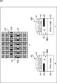
- FIG. 3 is a diagram illustrating a configuration example of a normal pixel 52.
- FIG. 3 is a diagram illustrating a configuration example of a detection pixel 53.
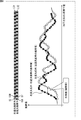
- FIG. It is a figure which shows the example of the series of each pixel value of the normal pixel 52, the left light shielding pixel 53L, and the right light shielding pixel 53L.
- FIG. 3 is a plan view illustrating a configuration example of a part of pixels on a light receiving surface 50.
- FIG. It is a figure explaining the light quantity received by each of the left light-shielding pixel 53L and the right light-shielding pixel 53R. It is a figure explaining an adjustment gain.
- FIG. 6 is a diagram for explaining that an error occurs in the defocus amount when the conversion coefficient varies depending on the position of the light receiving surface 50. It is a figure explaining a conversion factor. It is a top view which shows the example of the to-be-photographed object for the conversion coefficient setting process used in the conversion coefficient setting process which sets a conversion coefficient to a camera module.
- FIG. 3 is a block diagram illustrating a configuration example of a phase difference AF processing unit 17.
- FIG. It is a figure explaining the process of the phase difference AF process part.
- FIG. It is a flowchart explaining the example of the lens movement amount calculation process which calculates a lens movement amount. It is a flowchart following FIG. It is a figure explaining image height. It is a figure which shows the usage example which uses a camera module.
- FIG. 1 is a block diagram illustrating a configuration example of an embodiment of a camera module to which the present technology is applied.
- the camera module includes a lens barrel 11, an optical filter 12, an image sensor 13, a main processing unit 14, an illumination control unit 15, a sensor driving unit 16, a phase difference AF processing unit 17, an image processing unit 18, and a focus drive.
- a unit 19 a display unit 20, an operation unit 21, a flash memory 22, a focus actuator 23, and an illumination unit 24.
- the camera module is configured integrally with the lens barrel 11.
- the camera module can be configured such that the lens barrel 11 can be removed.
- the lens barrel 11 has an imaging optical system 11A such as a lens group and a diaphragm, and condenses light incident on the image sensor 13 via the optical filter 12.
- an imaging optical system 11A such as a lens group and a diaphragm
- the lens position (and hence the focal position) of the lens group of the image pickup optical system 11A can be moved in the direction of the optical axis L, so that the focus can be adjusted.
- the optical filter 12 is an optical element for reducing false colors and moire generated in a photographed image photographed by the image sensor 13. That is, the optical filter 12 is an optical low-pass filter, attenuates a part of the light component from the imaging optical system 11A, and outputs the attenuated component to the image sensor 13.
- the image sensor 13 is an imaging element that captures a captured image by receiving light (subject light) incident through the optical filter 12 from the imaging optical system 11A.
- CMOS ComplementarylementMetal ⁇ Oxide Semiconductor
- the image sensor 13 supplies a photographed image (image signal) obtained by photographing to the sensor driving unit 16.
- the main processing unit 14 controls each block constituting the camera module.
- the main processing unit 14 includes a CPU (Central Processing Unit) 31, a memory 32, an ADC (Analog to Digital Converter) 33, a DAC (Digital to Analog Converter) 34, and a communication I / F (Interface) 35.
- CPU Central Processing Unit
- ADC Analog to Digital Converter
- DAC Digital to Analog Converter
- I / F Interface
- the CPU 31 controls the illumination control unit 15 or the flash memory 22 by executing a program stored in the memory 32, and performs various operations such as AF, shooting of a shot image, various image processing, and recording of a shot image. Execute the process.
- the memory 32 includes a volatile memory such as a RAM (Random Access Memory), a non-volatile memory such as an EEPROM (Electrically Erasable Programmable Read Only Memory), and the like, and a program executed by the CPU 31 and data necessary for the operation of the CPU 31.
- a volatile memory such as a RAM (Random Access Memory)
- a non-volatile memory such as an EEPROM (Electrically Erasable Programmable Read Only Memory), and the like
- EEPROM Electrical Erasable Programmable Read Only Memory
- the data stored in the memory 32 includes AF parameters described later for phase difference AF.
- ADC33 AD converts analog signal to digital signal.
- the communication I / F 35 controls communication with the Internet or the like.
- the illumination control unit 15 controls the illumination unit 24 to emit light that illuminates the subject and light that becomes AF torch auxiliary light.
- the illumination control unit 15 causes the illumination unit 24 to emit (light) an electronic flash that is light that illuminates the subject in synchronization with the photographing operation of the image sensor 13.
- the illumination control unit 15 causes the illumination unit 24 to emit torch auxiliary light in synchronization with the AF operation.
- the sensor driving unit 16 controls the image sensor 13 to capture a captured image.
- the sensor driving unit 16 performs AD conversion on the image signal of the captured image captured by the image sensor 13 and supplies the image signal to the main processing unit 14 and the phase difference AF processing unit 17 as necessary.
- the phase difference AF processing unit 17 uses a pixel value of a detection pixel, which will be described later, of the image signal of the captured image from the sensor driving unit 16 to perform a lens of the imaging optical system 11A (lens group) by phase difference AF.
- a lens movement amount for moving the position is calculated and supplied to the main processing unit 14.
- the image processing unit 18 captures images captured by the image sensor 13 and supplied via the sensor driving unit 16 and the main processing unit 14, such as ⁇ conversion, color interpolation, JPEG (Joint Photographic Experts Group), and the like. Image processing such as compression / decompression by a predetermined compression / decompression method is performed. Further, the image processing unit 18 calculates a contrast evaluation value representing the contrast of the captured image and supplies it to the main processing unit 14. The main processing unit 14 performs contrast AF (control) using the contrast evaluation value from the image processing unit 18.
- the focus drive unit 19 drives the focus actuator 23 according to the control of the main processing unit 14 and adjusts the focus by moving the lens position of the imaging optical system 11A in the optical axis L direction.
- the display unit 20 includes, for example, an LCD (Liquid Crystal Display) panel and the like, and information on the shooting mode of the camera module, a preview image before shooting, a confirmation image after shooting, an image in a focused state during AF, and the like Is displayed.
- LCD Liquid Crystal Display
- the operation unit 21 is a group of switches operated by the user, and includes a power switch, a release (shooting trigger) switch, a zoom operation switch, a shooting mode selection switch, and the like.
- the flash memory 22 is detachable from the camera module. A captured image supplied from the main processing unit 14 is recorded (stored) in the flash memory 22.
- the focus actuator 23 is driven by the focus drive unit 19 to move the lens position of the imaging optical system 11A in the optical axis L direction.
- the illumination unit 24 emits light that illuminates the subject and light that serves as AF torch auxiliary light under the control of the illumination control unit 15.
- the illumination unit 24 for example, a flash illumination device using a xenon tube, an LED illumination device having an LED (Light Emitting Diode) capable of continuous light emission, or the like can be employed.
- a flash illumination device using a xenon tube an LED illumination device having an LED (Light Emitting Diode) capable of continuous light emission, or the like can be employed.
- LED Light Emitting Diode
- the camera module is mounted on a portable device such as a smartphone, a relatively small LED lighting device can be employed as the lighting unit 24.
- the illuminating unit 24 projects light onto a field through a projection lens (not shown) in which a groove having a predetermined pattern is formed, and improves AF accuracy for a dark subject or a low-contrast subject. Improve.
- the phase difference AF processing unit 17 can be included (built in) in the image sensor 13.
- phase difference AF processing unit 17 can be realized by hardware or can be realized by software.
- a program constituting the software is installed in, for example, a computer such as the main processing unit 14 and is executed by the CPU 31 of the main processing unit 14.
- the processing performed by the CPU 31 according to the program does not necessarily have to be performed in chronological order in the order described as a flowchart described later. That is, the processing performed by the CPU 31 according to the program includes processing executed in parallel or individually (for example, parallel processing or object processing).
- the program can be recorded in advance in a memory 32 as a recording medium built in the main processing unit 14 as a computer.
- the program can be stored (recorded) in a removable recording medium such as the flash memory 22 and provided as so-called package software.
- the program is downloaded to the main processing unit 14 via a communication network such as the Internet or a broadcasting network such as terrestrial and installed in the built-in memory 32. be able to.
- FIG. 2 is a plan view showing a configuration example of the image sensor 13 viewed from the imaging optical system 11A side.
- the image sensor 13 has a light receiving surface 50 that receives light, and the light receiving surface 50 is composed of H ⁇ V pixels in the horizontal and vertical directions.
- the block when the light receiving surface 50 is divided into, for example, rectangular blocks as a pixel group including a plurality of pixels is also referred to as a pixel block 51.
- 9 ⁇ 9 pixels are illustrated as a partial pixel group constituting the pixel block 51.
- a Bayer array R (Red), G (Green), or B (Blue) (primary color) color filter is formed on-chip.
- R pixel, G pixel, and B pixel the pixels on which the R, G, and B color filters are formed are referred to as R pixel, G pixel, and B pixel, respectively.
- the R pixel, G pixel, and B pixel have spectral sensitivities of R, G, and B, respectively, by on-chip color filters.
- G pixels are arranged at diagonal positions with 2 ⁇ 2 pixels in the horizontal and vertical directions as basic units, and R pixels and B pixels are arranged at the remaining two locations.
- an R pixel is arranged in the upper right
- a B pixel is arranged in the lower left
- a B pixel is arranged in the upper left and the lower right
- a G pixel is arranged.
- the basic units as described above are repeatedly arranged horizontally and vertically.
- the upper left G pixel of the basic unit is illustrated as Gr, and the lower right G pixel is illustrated as Gb.
- the detection pixel 53 for example, in order to receive light that has passed through the right half or the left half as a different region of the exit pupil of the imaging optical system 11A, The right half is shaded.
- the main component of luminance is acquired from the pixel value of the G pixel.
- FIG. 3 is a diagram illustrating a configuration example of the normal pixel 52.
- FIG. 3A is a plan view showing a configuration example of a region of only the normal pixel 52 in the light receiving surface 50.
- FIG. 3B is a cross-sectional view schematically showing a cross section of the normal pixel 52 taken along the line segment L11 of FIG. 3A.
- the normal pixel 52 has a configuration in which a PD (Photo Diode) 61, a CL (Contact Layer) 62, a color filter 63, and an on-chip lens (micro lens) 64 are stacked from the bottom in the drawing.
- a PD Photo Diode
- CL Contact Layer
- micro lens micro lens
- FIG. 4 is a diagram illustrating a configuration example of the detection pixel 53.
- FIG. 4A is a plan view showing a configuration example of a region including the detection pixel 53 in the light receiving surface 50.
- FIG. 4A is a plan view showing a configuration example of a region including the detection pixel 53 in the light receiving surface 50.
- a part of the G pixel among the R pixel, G pixel, and B pixel on the light receiving surface 50 is the detection pixel 53.
- a detection pixel a part of R pixel or B pixel can be adopted instead of the G pixel.
- a left light-shielding pixel 53L whose left half is shielded to receive light that has passed through each of the right half and the left half as different areas of the exit pupil of the imaging optical system 11A, There is a right light-shielding pixel 53R in which half is shielded.
- the left light-shielding pixel 53L and the right light-shielding pixel 53R are paired.
- 4B is a cross-sectional view schematically showing a cross section of the left light-shielding pixel 53L of the detection pixels 53 taken along the line segment L21 of FIG.
- 4C is a cross-sectional view schematically showing a cross section of the right light-shielding pixel 53R among the detection pixels 53 taken along the line segment L22 of FIG. 4A.
- the detection pixel 53 is common to the normal pixel 52 in that it includes a PD 61 or an on-chip lens 64. However, the detection pixel 53 is different from the detection pixel 53 in that a light shielding film 66 is provided on the CL 62.
- a light-shielding film 66 is provided so as to shield the left half of the left light-shielding pixel 53L. Accordingly, in the left light-shielding pixel 53L, only the right half is opened from the center of the on-chip lens 64 when viewed from the on-chip lens 64 side. As a result, the left light-shielding pixel 53L receives light that has passed, for example, the right half of the exit pupil of the imaging optical system 11A.
- a light-shielding film 66 is provided so as to shield the right half of the right light-shielding pixel 53R.
- the right light-shielding pixel 53R only the left half from the center of the on-chip lens 64 is opened as viewed from the on-chip lens 64 side.
- the right light-shielding pixel 53R receives light that has passed, for example, the left half of the exit pupil of the imaging optical system 11A.
- the pupil division in the horizontal direction (lateral direction) of the exit pupil of the imaging optical system 11A is performed.
- the detection pixels 53 are regularly arranged in the horizontal direction over the entire light receiving surface 50, for example. Increasing the number of detection pixels 53 improves the accuracy of the phase difference and thus the phase difference AF, but degrades the image quality of the captured image. Therefore, the number and arrangement position of the detection pixels 53 can be determined in consideration of a trade-off between the accuracy of the phase difference AF and the image quality of the captured image.
- the arrangement pattern of the detection pixels 53 can be a fixed pattern, or can be a different pattern depending on the location such as the central portion or the peripheral portion of the light receiving surface 50, for example.
- FIG. 5 is a diagram illustrating an example of a series of pixel values of the normal pixel 52, the left light-shielding pixel 53L, and the right light-shielding pixel 53L.
- a series of pixel values of the normal pixels 52 arranged in a line is also referred to as a normal series.
- a series of pixel values of the left light-shielding pixels 53L arranged in the line is also referred to as a left light-shielding series
- a series of pixel values of the right-shaded pixels 53R arranged in the line is also referred to as a right light-shielding series.
- FIG. 5 is a diagram illustrating a normal light and right light shielding series obtained from a line in which normal pixels 52 and right light shielding pixels 53R coexist, and a left light shielding light obtained from a line in which the left light shielding pixel 53L is paired with the right light shielding pixel 53R. A series is shown.
- the horizontal axis represents the pixel position
- the vertical axis represents the pixel value (brightness).
- the subject image that appears as a normal series is an image that appears as a left light-shielded series (hereinafter also referred to as a left light-shielded image) and an image that appears as a right light-shielded series ( Hereinafter, it is also referred to as a right light-shielded image).
- the focus of the subject image is determined based on the phase difference. It is possible to detect a defocus amount that is a shift amount of.
- FIG. 6 is a diagram illustrating an example of a right light-shielding series obtained from a line in which the right light-shielding pixel 53R exists and a left light-shielding series obtained from a line in which the left light-shielding pixel 53L paired with the right light-shielding pixel 53R is present. .
- the horizontal axis represents the pixel position
- the vertical axis represents the pixel value
- a part of the G pixels in the line L31 where the R pixel which is the normal pixel 52 exists is the right light-shielding pixel 53R.
- a part of the G pixels in the line L32 immediately after the line L31 is the left light-shielding pixel 53L.
- the right light-shielding pixel 53R and the left light-shielding pixel 53L diagonally to the left of the right light-shielding pixel 53R form a pair for detecting a phase difference (a left light-shielded image and a right light-shielded image).
- the phase difference can be obtained (detected) in units of the number of pixels using the left shading series and the right shading series.
- FIG. 7 is a diagram for explaining contrast AF (CDAF), phase difference AF (PDAF), and hybrid AF.
- the horizontal axis represents the lens position of the imaging optical system 11A
- the vertical axis represents the contrast evaluation value and the phase difference.
- the left direction on the horizontal axis represents the Inf (infinity) direction
- the right direction represents the macro (closest) direction.
- the Inf direction is a direction in which a subject at a far position is in focus
- the macro direction is a direction in which a subject at a near position is in focus.
- contrast AF In contrast AF (CDAF), a contrast evaluation value representing the contrast of a captured image is obtained at each lens position while moving the lens position. The lens position is moved so that the contrast evaluation value increases.
- the lens position Since the contrast evaluation value becomes maximum at the in-focus position, in contrast AF, the lens position is moved so as to approach the in-focus position, and once passes the in-focus position. Thereafter, the lens position is gradually moved so as to pass the focus position again, and the lens position where the contrast evaluation value is maximized, that is, the focus position is detected using the contrast evaluation value obtained at that time. The Then, the lens position is moved to the in-focus position where the contrast evaluation value is maximized.
- phase difference AF when the lens position is in the in-focus position, if the phase difference becomes zero, the lens position is directly moved so that the phase difference becomes zero.
- the lens position is moved closer to the in-focus position by phase difference AF, and then the lens position is accurately moved to the in-focus position by contrast AF.
- FIG. 8 is a diagram for explaining the relationship between the phase difference and the defocus amount.
- phase difference and the defocus amount both represent the amount of focus deviation of the subject image, but in AF, the defocus amount represents how far the current lens position is to the in-focus position. Used as a physical quantity.
- the defocus amount represents the distance and direction from the focus position to the current lens position.
- FIG. 8A is a diagram for explaining the defocus amount.
- the lens position where the contrast evaluation value is maximized is taken as the in-focus position, and the defocus amount represents the distance and direction from the in-focus position to the current lens position.
- um can be adopted as a unit of the defocus amount.
- the phase difference represents the amount of focus shift of the subject image as a relative positional relationship between the left light-shielded image and the right light-shielded image, and its unit is the number of pixels.
- FIG. 8B is a diagram showing the relationship between the phase difference and the defocus amount.
- the horizontal axis represents the phase difference
- the vertical axis represents the defocus amount
- the phase difference and the defocus amount have a linear relationship as shown in FIG. 8B, and therefore the phase difference and the defocus amount can be obtained from one to the other. .
- the defocus amount can be obtained according to Expression (1) using the phase difference.
- Defocus amount [um] phase difference [number of pixels] x conversion coefficient a [um / number of pixels] ... (1)
- the conversion characteristic is ideally represented by a straight line.
- the conversion coefficient a represents the slope of the conversion characteristic represented by a straight line.
- the conversion factor a can be obtained in advance (before shipment) by performing a test of the camera module at a manufacturing factory that manufactures the camera module.
- FIG. 9 is a plan view illustrating a configuration example of a part of pixels on the light receiving surface 50.
- FIG. 9 parts corresponding to those in FIGS. 3 and 4 are given the same reference numerals, and description thereof will be omitted below as appropriate.
- the on-chip lens 64, the light shielding film 66, and the like are formed (attached), the on-chip lens 64, the light shielding film 66, and the like are at their original positions (ideal positions). In some cases, misalignment (for example, misalignment during lithography) may occur.
- FIG 9A shows a pixel in which the light shielding film 66 is formed at the original position.
- the light-shielding film 66 is formed so as to shield the (substantially) left half of the left light-shielding pixel 53L, and the (substantially) right half is open.
- the light-shielding film 66 is formed so as to shield the (substantially) right half of the right light-shielding pixel 53R, and the (substantially) left half is open.
- FIG. 9B shows a pixel in which the light shielding film 66 is formed at a position shifted in the horizontal direction (right direction) from the original position.
- the light-shielding film 66 shields the left and right ends of the left light-shielding pixel 53L.
- the light-shielding film 66 shields most of the portion other than the left end of the right light-shielding pixel 53R.
- the left light shielding pixel 53L and the right light shielding pixel 53R are irradiated with the same amount of light, the left light shielding pixel 53L and the right light shielding pixel.
- the amount of light received by each of 53R is different.
- the pixel values of the left light-shielding pixel 53L and the right light-shielding pixel 53R are also different pixel values.
- FIG. 10 is a diagram for explaining the amount of light received by each of the left light-shielding pixel 53L and the right light-shielding pixel 53R when the left light-shielding pixel 53L and the right light-shielding pixel 53R are irradiated with the same amount of light.
- FIG. 10A shows the amount of light received by each of the left light shielding pixel 53L and the right light shielding pixel 53R when the light shielding film 66 is formed at the original position.
- the amounts of light received by the left light-shielding pixel 53L and the right light-shielding pixel 53R are the same.
- FIG. 10B shows the amount of light received by each of the left light shielding pixel 53L and the right light shielding pixel 53R when the light shielding film 66 is formed at a position shifted to the right from the original position.
- the amount of light received by the right light shielding pixel 53R is large, and the amount of light received by the left light shielding pixel 53L is small.
- FIG. 10C shows the amount of light received by each of the left light shielding pixel 53L and the right light shielding pixel 53R when the light shielding film 66 is formed at a position shifted to the left from the original position.
- the amount of light received by the right light shielding pixel 53R is small, and the amount of light received by the left light shielding pixel 53L is large.
- the light shielding film 66 when the light shielding film 66 is formed at a position shifted from the original position, the light amounts received by the left light shielding pixel 53L and the right light shielding pixel 53R are different from each other.
- the on-chip lens 64 is formed at a position shifted from the original position in addition to the light shielding film 66, the amount of light received by each of the left light shielding pixel 53L and the right light shielding pixel 53R is different. Become.
- misalignment of the on-chip lens 64 and the light shielding film 66 from the original position occurs at the time of manufacturing the camera module (image sensor 13).
- the misalignment varies depending on the camera module.
- various manufacturing errors may occur in parameters other than the positional deviation of the on-chip lens 64 and the light shielding film 66, but the manufacturing errors still have individual differences.
- AF parameters for phase difference AF i.e., for example, the conversion factor described above, adjustment gain, defocus offset, reliability threshold, phase difference offset, movement rate table, and lens position offset table described later are: It is obtained for each individual camera module and used in that camera module.
- any one or more of the conversion coefficient, adjustment gain, defocus offset, reliability threshold, phase difference offset, movement ratio table, and lens position offset table as AF parameters can be applied to multiple camera modules (eg, multiple camera modules manufactured in the same factory).
- FIG. 11 is a diagram for explaining the adjustment gain.
- FIG. 11 shows an example of a normal series, a left shading series, and a right shading series obtained when an all white chart is captured by the image sensor 13.
- the horizontal axis represents the horizontal position (x coordinate) of the pixel
- the vertical axis represents the pixel value (level).
- the normal series, the left shading series, and the right shading series are convex graphs having a peak near the center.
- the difference diffPP between the left peak value that is the maximum value of the left light-shielding series and the right peak value that is the maximum value of the right light-shielding series is correlated with, for example, the positional deviation of the light shielding film 66.
- the amount of light received by the left light-shielding pixel 53L and the right light-shielding pixel 53R varies depending on the positional deviation of the light-shielding film 66.
- the left peak value and the right peak value are equal and the difference diffPP is 0 if there is no positional shift.
- the light shielding film 66 is provided so as to shield the left half of the left light shielding pixel 53L in the left light shielding pixel 53L, and the light shielding film in the right light shielding pixel 53R. 66 is provided so as to shield the right half of the right light-shielding pixel 53R, the difference diffPA between the normal pixel peak value that is the maximum value of the normal series and the average value ave of the left peak value and the right peak value is The normal pixel peak value is 1 ⁇ 2.
- the amount of light received by each of the left light shielding pixel 53L and the right light shielding pixel 53R as a pair is different even when the image sensor 13 captures an all-white chart.
- the pixel values obtained are also different.
- the difference in the amount of light received by the left light-shielding pixel 53L and the right light-shielding pixel 53R as a pair means that the light-shielding film 66 is misaligned as well as the optical displacement of the imaging optical system 11A and the on-chip lens 64. This is also caused by the above.
- the pixel value of the detection pixel 53 (the left light-shielding pixel 53L and the right light-shielding pixel 53R) is corrected by the adjustment gain.
- the adjustment gain can be obtained according to equation (2).
- Adjustment gain pixel value of normal pixel 52 / pixel value of detection pixel 53 (2)
- the pixel value of the detection pixel 53 is the pixel value of the left light-shielding pixel 53L or the pixel value of the right light-shielding pixel 53R.
- FIG. 12 is a diagram illustrating an example of correction of the pixel value of the detection pixel 53 by the adjustment gain.
- an adjustment gain is obtained for each of the left light-shielding pixel 53L and the right light-shielding pixel 53R according to Equation (2).
- the adjustment gain is obtained by using the pixel value of the normal pixel 52 and the pixel value of the detection pixel 53 obtained by photographing an all white chart as a predetermined subject, for example, according to the equation (2). It is obtained by taking the ratio of the pixel value and the pixel value of the detection pixel 53.
- the pixel value is shown in FIG. As shown, it matches the pixel value of the normal pixel 52.
- the pixel value of the left light shielding pixel 53L is corrected by multiplying the pixel value of the left light shielding pixel 53L by the adjustment gain for the left light shielding pixel 53L.
- the pixel value of the right light-shielded pixel 53R is corrected by multiplying the pixel value of the right light-shielded pixel 53R by the adjustment gain for the right light-shielded pixel 53R.
- the phase difference is obtained using the pixel values of the detection pixels 53 (the left light shielding pixel 53L and the right light shielding pixel 53R) corrected using the adjustment gain.
- phase difference AF As described above, a highly accurate phase difference can be obtained by using the pixel value of the detection pixel 53 corrected using the adjustment gain. Furthermore, by performing phase difference AF using such a highly accurate phase difference, the accuracy of phase difference AF can be improved.
- FIG. 13 is a diagram illustrating an adjustment gain setting process for setting the adjustment gain in the camera module.
- FIG. 13 shows the light receiving surface 50 of the image sensor 13.
- the adjustment gain is obtained for each node that is a representative point representing a plurality of pixels constituting the pixel block 51.
- the center of gravity of the pixel block 51 can be used as the nodal point.
- ⁇ Nodal points can be identified by adding vertical and horizontal positions (coordinates) and numbers.
- FIG. 14 is a flowchart for explaining an example of the adjustment gain setting process.
- step S11 the main processing unit 14 sets the drive mode of the image sensor 13 via the sensor driving unit 16, and the process proceeds to step S12.
- examples of the drive mode include an all-pixel mode, a thinning mode, and a pixel addition mode.
- the all-pixel mode an image composed of pixel values of each pixel constituting the image sensor 13 is output as a captured image.
- the thinning mode an image composed of the pixel values of the thinned pixels obtained by thinning pixels from the pixels constituting the image sensor 13 with a predetermined pattern is output as a captured image.
- the pixel addition mode an image having a pixel value obtained by adding the pixel values of the pixels constituting the image sensor 13 in a predetermined pattern is output as a captured image.
- step S12 the main processing unit 14 moves the lens position of the imaging optical system 11A to a predetermined fixed position in the macro direction, for example, by controlling the focus actuator 23 via the focus driving unit 19. Advances to step S13.
- an object of white color is prepared as an object for the adjustment gain setting process.
- the adjustment gain setting processing subject and the camera module are known so as to be in focus when the lens position of the imaging optical system 11A is a predetermined fixed position in the macro direction. Set to a distance of
- step S13 the main processing unit 14 sets shooting conditions for shooting a white subject that is the subject for the adjustment gain setting process, and the process proceeds to step S14.
- the shooting conditions set in step S13 include, for example, shutter speed and AE (Automatic Exposure) gain.
- step S ⁇ b> 14 the image sensor 13 shoots a white-colored subject (chart) that is a subject for the adjustment gain setting process, and a captured image obtained by the shooting is captured via the sensor driving unit 16 in the main processing unit 14. The process proceeds to step S15.
- step S15 the main processing unit 14 obtains an adjustment gain for the detection pixel 53 (each of the left light-shielding pixel 53L and the right light-shielding pixel 53R) using the captured image from the image sensor 13 according to the equation (2).
- the main processing unit 14 sequentially selects each pixel block 51 as a target block. For each of the left light-shielding pixel 53L and the right light-shielding pixel 53R that are the detection pixels 53 in the block of interest, the main processing unit 14 uses a representative value such as an average value of the adjustment gain for the left light-shielding pixel at the node of the block of interest. The adjustment gain and the adjustment gain for the right light-shielded pixel are obtained, and the process proceeds from step S15 to step S16.
- step S16 the main processing unit 14 determines whether or not the adjustment gain obtained in step S15 is a value within a range predetermined as a manufacturing standard (hereinafter also referred to as a value within the manufacturing standard).
- step S16 If it is determined in step S16 that the adjustment gain is not a value within the manufacturing standard, the adjustment gain setting process ends. In this case, since the camera module may be defective, the camera module is sent for inspection, for example.
- step S16 determines whether the adjustment gain is a value within the manufacturing standard. If it is determined in step S16 that the adjustment gain is a value within the manufacturing standard, the process proceeds to step S17.
- step S ⁇ b> 17 the main processing unit 14 writes the adjustment gain for the left light-shielded pixel and the adjustment gain for the right light-shielded pixel for each node of the pixel block 51 obtained in step S ⁇ b> 15 in the memory 32 and adjusts the gain.
- the setting process ends.
- the adjustment gain for the left light-shielded pixel and the adjustment gain for the right light-shielded pixel at the node of each pixel block 51 are written in the memory 32, so that the adjustment gain is set in the camera module.
- correction of the pixel value of the left light-shielded pixel 53L of a certain pixel block 51 can be performed by, for example, multiplying the adjustment gain for the left light-shielded pixel at the node of the pixel block 51.
- the correction of the pixel value of the left light-shielded pixel 53L of a certain pixel block 51 is obtained by, for example, (three-dimensional) interpolation using an adjustment gain for the left light-shielded pixel at the node of each pixel block 51. This can be done by multiplying the interpolation value of the adjustment gain at the position 53L.
- the adjustment gain for each nodal point is written (stored) in the memory 32, but the adjustment gain for each detection pixel 53 can be written in the memory 32.
- the adjustment gain for each detection pixel 53 is written in the memory 32, the correction accuracy of the pixel value of the detection pixel 53 by the adjustment gain can be improved, but the storage capacity for storing the adjustment gain in the memory 32 is large. Become big.
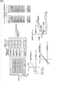
- FIG. 15 is a diagram showing an example of conversion characteristics that are the relationship between the phase difference and the defocus amount.
- the horizontal axis represents the phase difference and the vertical axis represents the defocus amount, but in FIG. 15, the horizontal axis and the vertical axis are interchanged. That is, in FIG. 15, the horizontal axis represents the defocus amount, and the vertical axis represents the phase difference.
- DAC value
- the DAC is a control unit for controlling the VCM when the VCM (Voice Coil Motor) is adopted as the focus actuator 23.
- the DAC as the defocus amount, for example, a value represented by 10 bits (range from 0 to 1023) can be adopted.
- FIG. 15 shows three conversion characteristics R # 1, R # 2, and R # 3.
- the conversion characteristic R # 1 is a conversion characteristic for the detection pixel 53 at the center of the light receiving surface 50 of the image sensor 13, that is, a conversion characteristic that is a relationship between the phase difference obtained from the detection pixel 53 at the center and the defocus amount. Represents.
- the conversion characteristic R # 2 represents the conversion characteristic for the detection pixel 53 in the part of the periphery of the light receiving surface 50 of the image sensor 13 that is separated from the center part in the horizontal direction.
- the conversion characteristic R # 3 represents the conversion characteristic of the detection pixel 53 in a portion away from the central portion in the diagonal direction in the peripheral portion of the light receiving surface 50 of the image sensor 13.
- the position farthest from the center in the lateral direction Is about 64%.
- Conversion characteristics R # 1 to R # 3 represent conversion characteristics for the detection pixels 53 at positions of 0%, 64%, and 100%, respectively.
- the reciprocal 1 / a of the conversion characteristic a which is the inclination, becomes smaller as the conversion characteristic for the detection pixel 53 at a position away from the center of the light receiving surface 50 of the image sensor 13 is obtained. That is, it can be confirmed that the conversion characteristic a is increased.
- the conversion characteristics that is, the conversion coefficient a varies depending on the position of the light receiving surface 50.
- the conversion coefficient a is obtained only for the detection pixel 53 at a certain position, such as the detection pixel 53 at the center of the light receiving surface 50 of the image sensor 13, and the conversion coefficient a is calculated for all the image sensors 13.
- the defocus amount is obtained using the detection pixel 53, an error may occur in the defocus amount.
- FIG. 16 is a diagram for explaining that an error occurs in the defocus amount when the conversion coefficient “a” varies depending on the position of the light receiving surface 50.
- FIG. 16 shows a conversion characteristic (hereinafter also referred to as center conversion characteristic) R # 1 for the detection pixel 53 at the center of the light receiving surface 50 and a conversion coefficient (hereinafter referred to as the detection pixel 53 at the periphery of the light receiving surface 50).
- R # 1 a conversion characteristic for the detection pixel 53 at the center of the light receiving surface 50
- R # 2 a conversion coefficient for the detection pixel 53 at the periphery of the light receiving surface 50.
- the horizontal axis represents the lens position of the imaging optical system 11A
- the vertical axis represents the phase difference and the contrast evaluation value.
- the left direction is the Inf direction
- the right direction is the macro direction
- the in-focus position is assumed to be the lens position where the contrast evaluation value is maximized.
- phase difference x1 is detected from the detection pixel 53 at the center of the light receiving surface 50.
- the defocus amount y1 is obtained for the phase difference x1
- the defocus amount y1 is obtained with respect to the phase difference x1.
- a large defocus amount y2 is required.
- the defocus amount y1 obtained using the center conversion characteristic R # 1 is appropriate.
- the peripheral conversion is performed with respect to the phase difference x1 obtained from the detection pixel 53 at the center of the light receiving surface 50.
- the defocus amount y2 is obtained using the characteristic R # 2.
- the defocus amount y2 is larger than the defocus amount y1 appropriate for the phase difference x1 obtained from the detection pixel 53 at the center of the light receiving surface 50, and has an error.
- the lens position of the imaging optical system 11A When the lens position of the imaging optical system 11A is moved according to the defocus amount y2, the lens position goes too far from the in-focus position, and the accuracy of the phase difference AF deteriorates.
- the conversion coefficient a is set for each of a plurality of positions on the light receiving surface 50, and the defocus amount is obtained by using the conversion coefficient a.
- FIG. 17 is a diagram for explaining the conversion coefficient a.
- the horizontal axis represents the phase difference and the vertical axis represents the defocus amount, as in B of FIG.
- the conversion coefficient a is the slope of the conversion characteristic that represents the relationship between the phase difference and the defocus amount, and is obtained according to Equation (3).
- FIG. 18 is a plan view showing an example of a subject for the conversion coefficient setting process used in the conversion coefficient setting process for setting the conversion coefficient in the camera module.
- a slit subject with a slit can be adopted.
- a subject having a high contrast can be adopted so that a phase difference with high accuracy can be detected.
- FIG. 19 is a flowchart for explaining an example of the conversion coefficient setting process.
- the conversion coefficient setting process for example, as in the adjustment gain described with reference to FIG. 14, the conversion coefficient is obtained for each node that is a representative point representing a plurality of pixels constituting the pixel block 51.
- step S21 the main processing unit 14 sets the drive mode of the image sensor 13 as in step S11 of FIG. 14, and the process proceeds to step S22.
- step S22 as in step S13 of FIG. 14, the main processing unit 14 sets shooting conditions for shooting a slit subject that is a subject for the conversion coefficient setting process, and the process proceeds to step S23.
- step S ⁇ b> 23 the main processing unit 14 controls the focus actuator 23 via the focus driving unit 19, thereby changing the lens position of the imaging optical system 11 ⁇ / b> A from the position in the macro direction to the position in the Inf direction. Move sequentially to the position.
- the subject for the conversion coefficient setting process and the camera module are set at a known distance. Therefore, the in-focus position and the defocus amount with respect to the lens position of the imaging optical system 11 are known.
- step S23 The movement of the lens position in step S23 is performed across the in-focus position.
- step S23 as described above, the lens position of the imaging optical system 11A is sequentially moved to a plurality of positions.
- the image sensor 13 photographs a slit subject that is a subject for conversion coefficient setting processing. To do.
- the captured image captured by the image sensor 13 when the lens position of the imaging optical system 11A is moved to each of a plurality of positions is supplied to the main processing unit 14 via the sensor driving unit 16.
- the main processing unit 14 obtains the phase difference from the pixel values of the detected pixels of the pixel block 51 for each pixel block 51 of the captured image captured at each of the plurality of lens positions as described above. Further, the main processing unit 14 acquires the defocus amount with respect to the lens position when the phase difference obtained from the pixel value of the detection pixel of the pixel block 51 is obtained.
- the subject for the conversion coefficient setting process and the camera module are set at a known distance, and the defocus amount with respect to the lens position is known.
- step S23 When the main processing unit 14 obtains a set of phase difference and defocus amount for each pixel block 51 for each of a plurality of lens positions, the process proceeds from step S23 to step S24, and the main processing unit 14 For each point, a conversion coefficient a is obtained.
- the main processing unit 14 sequentially selects each pixel block 51 as a target block.
- the main processing unit 14 is defined by Expression (3) using the phase difference obtained from the detection pixel 53 of the block of interest for each of a plurality of lens positions and the defocus amount set as the phase difference.
- the conversion coefficient a is calculated as the conversion coefficient a of the nodal point of the target block.
- step S23 a plurality of sets of phase differences and defocus amounts are obtained for the block of interest.
- the least square method is applied to a plurality of sets of the phase difference and the defocus amount for the block of interest, and the conversion coefficient a of the node of the block of interest can be obtained.
- the conversion coefficient a is obtained according to the equation (3), and the conversion obtained for each of the plurality of sets.
- a representative value such as an average value of the coefficient a can be obtained as the conversion coefficient a of the nodal point of the block of interest.
- step S24 When the conversion factor a of the nodal point of each pixel block 51 is obtained, the process proceeds from step S24 to step S25.
- step S25 the main processing unit 14 determines whether or not the conversion coefficient a obtained in step S24 is a value within the manufacturing standard. Whether or not the conversion coefficient a is a value within the manufacturing standard can be determined based on whether or not a PDAF focusing position error, which will be described later, obtained from the conversion coefficient a is within a predetermined threshold.
- step S25 If it is determined in step S25 that the conversion coefficient a is not a value within the manufacturing standard, the conversion coefficient setting process ends. In this case, since the camera module may be defective, the camera module is sent for inspection, for example.
- step S25 when it is determined in step S25 that the conversion coefficient a is a value within the manufacturing standard, the process proceeds to step S26.
- step S26 the main processing unit 14 writes the conversion coefficient a of the nodal point of each pixel block 51 obtained in step S24 into the memory 32, and the conversion coefficient setting process ends.
- the conversion coefficient a of the nodal point of each pixel block 51 is written in the memory 32, whereby the conversion coefficient a is set in the camera module.
- the conversion of the phase difference obtained from the detection pixel 53 in a certain pixel block 51 into the defocus amount is performed using the conversion coefficient a of the nodal point of the pixel block 51.
- FIG. 20 is a diagram for explaining the defocus offset.
- the horizontal axis represents the lens position
- the vertical axis represents the phase difference and the contrast evaluation value.
- the phase difference AF may not be as accurate as the contrast AF.
- the lens position where the contrast evaluation value is maximized in contrast AF is finally the in-focus position. Therefore, in order to increase the speed of hybrid AF, it is important to move the lens position as close as possible to the lens position where the contrast evaluation value is maximized as the in-focus position in phase difference AF.
- FIG. 20 shows an actual relationship between the lens position, the contrast evaluation value, and the phase difference.
- the lens position where the contrast evaluation value is maximized is also called the contrast AF focusing position.
- the current lens position that is, for example, the position where phase difference AF is started in hybrid AF is also referred to as the PDAF execution position, and the lens position after movement according to the defocus amount in phase difference AF is changed to PDAF alignment. It is also called a focal position.
- the PDAF in-focus position is a position where the lens position is moved from the PDAF execution position so that the defocus amount obtained at the PDAF execution position is zero.
- the defocus amount is obtained by multiplying the phase difference obtained at the PDAF execution position by the conversion coefficient a.
- the PDAF focusing position can be obtained according to the equation (4).
- the PDAF focus position error is expressed by Expression (5).
- PDAF focus position error PDAF focus position-Contrast AF focus position (5)
- the PDAF in-focus position error in equation (5) may not be zero due to manufacturing errors.
- the defocus amount here, the distance from the contrast AF focus position to the PDAF execution position
- the PDAF focus position error tends to increase.
- the first factor that increases the PDAF focus position error as the defocus amount increases is that the image on the detection pixel 53 is blurred when the defocus amount is large.
- the image on the detection pixel 53 is blurred, the contrast of the left light-shielded image and the right light-shielded image obtained as a series of pixel values of the detection pixel 53 is lost, and the phase difference accuracy obtained from the left light-shielded image and the right light-shielded image is lost. Gets worse.
- the second factor that increases the PDAF focus position error as the defocus amount increases the greater the defocus amount, the greater the amount of deviation between the left and right light-shielded images.
- the amount of deviation the amount of deviation corresponding to the distance that can be measured
- the coincidence between the left light-shielded image and the right light-shielded image is lowered, and the accuracy of the phase difference obtained from the left light-shielded image and the right light-shielded image is deteriorated.
- the PDAF focus position error is obtained as a defocus offset that is an offset of the defocus amount, and the defocus amount is corrected by the defocus offset, thereby improving the accuracy of the phase difference AF.
- FIG. 21 is a diagram for explaining a defocus offset calculation method and a defocus amount correction method using the defocus offset.
- the defocus offset can be calculated from PDAF in-focus position error according to equation (6).
- the PDAF in-focus position error can be obtained using the PDAF in-focus position and the contrast AF in-focus position according to the equation (5).
- the PDAF focus position can be obtained according to equation (4).
- the contrast AF focus position can be obtained as the lens position where the contrast evaluation value is maximized.
- the contrast evaluation value can be obtained from the image processing unit 18.
- the defocus amount obtained from the phase difference is changed to the defocus amount for moving the lens position from the current position to the contrast AF in-focus position according to Equation (7). It is corrected.
- Defocus amount after correction Defocus amount + Defocus offset (7)
- FIG. 22 is a flowchart for explaining an example of defocus offset setting processing for setting a defocus offset in the camera module.
- the slit subject in FIG. 18 can be employed as the subject for the defocus offset setting process.
- the defocus offset is obtained for each nodal point (FIG. 13) that is a representative point representing a plurality of pixels constituting the pixel block 51. .
- step S41 the main processing unit 14 sets the drive mode of the image sensor 13 as in step S11 of FIG. 14, and the process proceeds to step S42.
- step S42 as in step S13 of FIG. 14, the main processing unit 14 sets shooting conditions for shooting a slit subject, which is a subject for the defocus offset setting process, and the process proceeds to step S43.
- step S43 the main processing unit 14 controls the focus actuator 23 via the focus driving unit 19 to change the lens position of the imaging optical system 11A from the position in the macro direction, as in step S23 of FIG. Move sequentially to multiple positions in the Inf direction.
- step S43 as described above, the lens position of the imaging optical system 11A is sequentially moved to a plurality of positions.
- the image sensor 13 photographs the slit subject.
- the captured image captured by the image sensor 13 when the lens position of the imaging optical system 11A is moved to each of a plurality of positions is supplied to the main processing unit 14 via the sensor driving unit 16.
- the main processing unit 14 obtains the phase difference from the pixel values of the detected pixels of the pixel block 51 for each pixel block 51 of the captured image captured at each of the plurality of lens positions as described above.
- the main processing unit 14 controls the image processing unit 18 to obtain a contrast evaluation value for the captured images captured at each of a plurality of lens positions.
- step S43 the main processing unit 14 obtains the pixel block 51 for each pixel block 51 using the conversion coefficient a obtained in the conversion coefficient setting process of FIG.
- a defocus amount is obtained from the obtained phase difference.
- the main processing unit 14 uses the defocus amount for each pixel block 51 to obtain the PDAF in-focus position according to Expression (4).
- the main processing unit 14 determines, based on the contrast evaluation value obtained by the image processing unit 18, the lens position where the contrast evaluation value is the maximum for the captured image captured at each of the plurality of lens positions. Find as position.
- the main processing unit 14 obtains the PDAF in-focus position for the captured image captured at each of the plurality of lens positions for each pixel block 51.
- a representative value such as an average value of PDAF focus positions obtained for captured images taken at a plurality of lens positions is obtained as the PDAF focus position for the pixel block 51.
- step S44 the main processing unit 14 determines, for each nodal point. Find the defocus offset.
- step S45 the main processing unit 14 sequentially selects each pixel block 51 as a target block.
- the main processing unit 14 uses the PDAF focus position of the block of interest and the contrast AF focus position to determine the PDAF focus position error of equation (5) as a defocus offset of the node of the block of interest, and performs processing Advances from step S45 to step S46.
- step S46 the main processing unit 14 determines whether or not the defocus offset obtained in step S45 is a value within the manufacturing standard.
- step S46 If it is determined in step S46 that the defocus offset is not a value within the manufacturing standard, the defocus offset setting process ends. In this case, since the camera module may be defective, the camera module is sent for inspection, for example.
- step S46 determines whether the defocus offset is a value within the manufacturing standard. If it is determined in step S46 that the defocus offset is a value within the manufacturing standard, the process proceeds to step S47.
- step S47 the main processing unit 14 writes the defocus offset of the nodal point of each pixel block 51 obtained in step S45 into the memory 32, and the defocus offset setting process ends.
- the defocus offset of the nodal point of each pixel block 51 is written in the memory 32, whereby the defocus offset is set in the camera module.
- the correction of the defocus amount obtained from the phase difference obtained from the detection pixel 53 in a certain pixel block 51 is performed according to Expression (7) using the defocus offset of the nodal point of the pixel block 51. Is called.
- the process of obtaining the PDAF focus position error can be performed a plurality of times.
- the average value of the PDAF in-focus position error obtained by the plurality of processes can be used as the defocus offset.
- FIG. 23 is a diagram showing an outline of the relationship between the reliability threshold value of the phase difference reliability and the sensor gain of the image sensor 13.
- the horizontal axis represents the sensor gain of the image sensor 13
- the vertical axis represents the phase difference reliability (reliability threshold).
- the image plane phase difference AF method does not have a very wide defocus amount, and thus the range in which the phase difference can be measured. Therefore, when the defocus amount is large and the phase difference deviates from the range that can be measured (when the subject is blurred), it is difficult to perform the phase difference AF.
- the phase difference reliability is an index for determining whether or not the phase difference is within a range that can be measured, and the reliability to the extent that an accurate defocus amount can be obtained from the phase difference. To express.
- phase difference reliability for example, a value defined by Equation (8) can be adopted.
- Phase difference reliability ⁇
- the phase difference reliability of Expression (8) represents, for example, the phase difference reliability of the phase difference obtained from the detection pixel 53 included in the target block with one pixel block 51 as the target block. .
- X i represents the position of the i-th detection pixel 53 of the block of interest
- Y i represents the pixel value of the detection pixel 53 at the position X i
- ⁇ represents summation for all the detection pixels 53 in the block of interest.
- Equation (8) the total sum of the ratios of changes in the pixel values of the detection pixels 53 included in the target block is obtained as the phase difference reliability of the phase difference obtained from the detection pixels 53 included in the target block.
- Equation (8) Note that the phase difference reliability of Equation (8) is described in Japanese Patent Application Laid-Open No. 2010-139942 previously proposed by the applicant.
- phase difference reliability in addition to the first value obtained by Expression (8), a second value representing the coincidence between the left light-shielded image and the right light-shielded image, and a third value representing the contrast of the captured image. Or a value corresponding to two or more of the first to third values can be adopted.
- the reason why the third value representing the contrast can be adopted as the phase difference reliability is that the higher the contrast, the easier it is to detect the phase difference with high accuracy.
- phase difference reliability for example, a value obtained by Expression (8) itself, a value obtained by normalizing the value obtained by Expression (8) with the maximum value obtained by Expression (8) as 100%, etc. Can be adopted.
- the sensor gain of the image sensor 13 includes any gain that can be applied as a function of adjusting the exposure (exposure) so that the pixel value obtained in the pixel does not become saturated or blackened.
- a function for adjusting the exposure for example, there is an AE for adjusting an aperture, a shutter speed, and the like.
- the sensor gain of the image sensor 13 is high when shooting a dark scene with low illuminance.
- the S / N (Signal to Noise ratio) of the captured image depends on the exposure mode of the image sensor 13 and the like, but becomes worse as the sensor gain increases. Therefore, as the sensor gain is higher, noise is more likely to be included in the pixel value of the detection pixel 53, and an error is likely to occur in the phase difference obtained from the pixel value.
- the sensor gain includes a so-called secondary sensor gain such as sharding correction in addition to a so-called primary sensor gain such as AE gain (gain applied as AE). is there.
- secondary sensor gain such as sharding correction
- primary sensor gain such as AE gain (gain applied as AE).
- the phase difference may be trusted when the sensor gain is small, but the phase difference is trusted when the sensor gain is large. There should be no.
- the reliability threshold value used for thresholding the phase difference reliability a value that increases with increasing sensor gain is introduced as shown in FIG. 23, and the phase difference reliability larger than the reliability threshold value is introduced. Only the phase difference is determined to be reliable and used for phase difference AF.
- the phase difference for which a certain level of phase difference reliability has been obtained is the phase difference when the sensor gain is high and errors are likely to occur. Also, it is determined that the phase difference is reliable.
- the reliability threshold that increases with an increase in sensor gain, even if the phase difference has a certain degree of phase difference reliability, the phase difference has a high sensor gain and an error. When the phase difference is likely to occur, it is possible to prevent the phase difference from being determined to be reliable.
- the reliability threshold value for example, the phase difference reliability with respect to a predetermined sensor gain at each lens position is obtained for each pixel block 51, and a predetermined coefficient is calculated for the average value, median value, and maximum value of the phase difference reliability.
- a value obtained by multiplying by is obtained as a reliability threshold value for a predetermined sensor gain at the node of each pixel block 51.
- a reliability threshold for each of the plurality of sensor gains is obtained for the node of each pixel block 51.
- a reliability threshold for a certain sensor gain G is smaller than a reliability threshold for a sensor gain G ′ lower than the sensor gain G at a node of a certain pixel block 51, the reliability threshold for the sensor gain G is , The sensor gain G ′ is corrected to a value larger than the reliability threshold value.
- FIG. 24 is a diagram for explaining a reliability threshold calculation method for an arbitrary sensor gain G and a phase difference reliability determination method using the reliability threshold.
- FIG. 24A is a diagram for explaining a method of calculating a reliability threshold for an arbitrary sensor gain G.
- the reliability threshold value TH for an arbitrary sensor gain G is obtained by interpolation using four reliability threshold values TH [0] to TH [3].
- the sensor gain G is a value between the sensor gains G [2] and G [3]
- the reliability threshold value TH for the sensor gain G is the reliability for the sensor gain G [2].
- the threshold value TH [2] is obtained by linear interpolation between the sensor threshold value G [3] and the reliability threshold value TH [3].
- the interpolation method for obtaining the reliability threshold TH is not limited to linear interpolation.
- FIG. 24B is a diagram for explaining a method of determining the reliability of the phase difference using the reliability threshold value.
- the current sensor gain is the value G
- the phase difference reliability of the value R is required for the sensor gain G from the detection pixel 53 of a certain pixel block 51.
- the reliability threshold values for the four sensor gains G [0] to G [3] at the nodal point of the pixel block 51 for which the phase difference reliability R is obtained are the values TH [0 ] Or TH [3].
- the reliability thresholds TH [0] to TH [3] obtained for the node of the pixel block 51 for which the phase difference reliability R is obtained are used.
- the reliability threshold TH for the sensor gain G is obtained by the interpolation performed.
- phase difference reliability R when the phase difference reliability R is equal to or less than the reliability threshold value TH (or less than), it is determined that the phase difference is not reliable. Further, when the phase difference reliability R is larger (or higher) than the reliability threshold value TH, it is determined that the phase difference is reliable.
- FIG. 25 is a flowchart for explaining an example of the reliability threshold setting process for setting the reliability threshold in the camera module.
- the slit subject in FIG. 18 can be adopted as the subject for the reliability threshold setting process, as in the case of the conversion coefficient setting process.
- the reliability threshold value setting process for example, as in the conversion coefficient setting process, the reliability threshold value is obtained for each nodal point (FIG. 13) that is a representative point representing a plurality of pixels constituting the pixel block 51. .
- step S61 the main processing unit 14 sets the drive mode of the image sensor 13 as in step S11 of FIG. 14, and the process proceeds to step S62.
- step S62 as in step S13 of FIG. 14, the main processing unit 14 sets shooting conditions for shooting a slit subject, which is a subject for reliability threshold setting processing, and the process proceeds to step S63.
- step S63 the main processing unit 14 controls the focus actuator 23 via the focus driving unit 19 to change the lens position of the imaging optical system 11A from the position in the macro direction, as in step S23 of FIG. Move sequentially to multiple positions in the Inf direction.
- the main processing unit 14 sequentially sets the sensor gain of the image sensor 13 to a plurality of values at each lens position.
- step S63 as described above, while the lens position of the imaging optical system 11A is sequentially moved to a plurality of positions, the sensor gain is sequentially set to a plurality of values at each lens position.
- the image sensor 13 photographs the slit subject.
- the lens position of the imaging optical system 11A When the lens position of the imaging optical system 11A is moved to each of a plurality of positions, the captured image captured by the image sensor 13 with each of a plurality of sensor gains is subjected to main processing via the sensor driving unit 16. Supplied to the unit 14.
- the main processing unit 14 determines the phase difference reliability based on the pixel value of the detection pixel of the pixel block 51 for each pixel block 51 of the captured image of each of the plurality of sensor gains captured at each of the plurality of lens positions. Seeking sex.
- step S63 the main processing unit 14 uses the phase difference reliability of each of the plurality of lens positions for the nodal point of each pixel block 51 to determine the reliability for each of the plurality of sensor gains. Find the threshold.
- phase difference reliability at each of a plurality of lens positions is obtained for each of a plurality of sensor gains.
- the main processing unit 14 uses the phase difference reliability at each of a plurality of lens positions for one pixel block 51 to obtain a reliability threshold value for each of a plurality of sensor gains as described with reference to FIG. .
- step S64 When the reliability threshold value for each of the plurality of sensor gains is obtained for the node of each pixel block 51, the process proceeds from step S64 to step S65.
- step S65 the main processing unit 14 determines whether or not the reliability threshold obtained in step S64 is a value within the manufacturing standard.
- step S65 If it is determined in step S65 that the reliability threshold value is not within the manufacturing standard, the reliability threshold value setting process ends. In this case, since the camera module may be defective, the camera module is sent for inspection, for example.
- step S65 when it is determined in step S65 that the reliability threshold value is within the manufacturing standard, the process proceeds to step S66.
- step S66 the main processing unit 14 writes the reliability threshold value for each of the plurality of sensor gains for the node of each pixel block 51 obtained in step S64 in the memory 32, and the reliability threshold value setting process ends. .
- the reliability threshold value for each of the plurality of sensor gains for the nodal point of each pixel block 51 is written in the memory 32, whereby the reliability threshold value is set in the camera module.
- the phase difference reliability of the phase difference and the reliability threshold value for each of the plurality of sensor gains for the node of the pixel block 51 As described with reference to FIG. 24, the reliability is determined.
- FIG. 26 is a diagram showing an example of conversion characteristics representing the actual relationship between the defocus amount and the phase difference.
- the defocus amount and the phase difference ideally have a linear relationship, and the conversion characteristic is represented by a straight line.
- the ideal linear conversion characteristic is called the ideal characteristic.
- the actual defocus amount is a value D0 smaller than the value D1 obtained from the ideal characteristic according to the actual conversion characteristic.
- FIG. 27 is a diagram illustrating examples of ideal characteristics, offset characteristics, and contrast evaluation values.
- the lens position is moved according to the defocus amount D1
- the position after the movement is too far from the in-focus position, that is, the lens position where the contrast evaluation value is maximized.
- the phase difference P1 On the other hand, a defocus amount D1 larger than the actual defocus amount D0 is obtained.
- the lens position is moved from the actual position r0 so that the defocus amount D1 obtained from the ideal characteristics becomes zero. As a result, the lens position passes the in-focus position.
- the offset of the phase difference between the linear ideal characteristic represented by the conversion coefficient and the non-linear characteristic (hereinafter also referred to as the actual characteristic) representing the actual relationship between the phase difference and the defocus amount.
- the phase difference is corrected using the phase difference offset.
- the defocus amount is calculated using the corrected phase difference corrected using the phase difference offset, thereby preventing a defocus amount larger than the actual defocus amount from being calculated. As a result, the accuracy of phase difference AF is improved.
- FIG. 28 is a diagram for explaining the calculation of the phase difference offset and the correction of the phase difference using the phase difference offset.
- phase difference offset by moving the lens position of the imaging optical system 11A to a plurality of positions, a set of actual phase differences and defocus amounts is obtained for each of the plurality of lens positions.
- phase difference and defocus amount are also referred to as measurement phase difference and measurement defocus amount, respectively.
- a plurality of lens positions are sequentially selected as the target position.
- the lens position at which the measurement defocus amount is the value D11 is selected as the target position.
- phase difference P10 phase difference (hereinafter also referred to as an ideal phase difference) P10 with respect to the measurement defocus amount D11 at the target position is obtained. From the ideal characteristics, a set with the measurement defocus amount D11 is obtained. By subtracting the measured phase difference P11, the phase difference offset Poff11 with respect to the measured phase difference P11 is obtained.
- the phase difference offset is obtained for the measured phase difference at each of the plurality of lens positions.
- the phase difference obtained from the pixel value of the detection pixel 53 by interpolation using the phase difference offset obtained for the measured phase difference at each of the plurality of lens positions that is, For example, the phase difference offset Poff13 with respect to the phase difference P13 in FIG. 28 is obtained.
- phase difference P13 is corrected to the value P13-Poff13 by subtracting the phase difference offset Poff13 (absolute value thereof) from the phase difference P13.
- the defocus amount D13 with respect to the corrected phase difference P13-Poff13 is obtained using ideal characteristics.
- the defocus amount D13 is a defocus amount with respect to the phase difference P13 in the actual characteristics. Therefore, by correcting the phase difference using the phase difference offset, the actual defocus amount is obtained using the ideal characteristics. Can be requested.
- the defocus amount of the actual characteristic can be obtained using the ideal characteristic with respect to the phase difference.
- a phase difference offset (hereinafter also referred to as a measured phase difference offset group) with respect to the measured phase difference at each of the plurality of lens positions is used as a camera module. It is necessary to set to.
- the measurement phase difference offset group is set in the camera module, for example, the measurement phase difference offset group is stored in the memory 32, or the measurement phase difference offset group is included (embedded) in the program executed by the CPU 31. Can be done by.
- FIG. 29 is a diagram showing an example of a part of the contents stored in the memory 32 of FIG.
- the total number N + 1 of nodes [n] is 25.
- the memory 32 stores the defocus offset d [n] for each node [n] by the defocus offset setting process of FIG.
- FIG. 30 is a block diagram illustrating a configuration example of the phase difference AF processing unit 17 in FIG.
- the phase difference AF processing unit 17 includes a sequence separation unit 81, a reliability determination unit 82, multiplication units 83 and 84, a phase difference AF calculation unit 85, an AF frame setting unit 86, and an acquisition unit 87.
- the series separation unit 81 is supplied with the pixel value of the detection pixel 53 among the pixel values output from the image sensor 13 from the sensor driving unit 16.
- the sensor drive unit 16 has a black level correction unit (not shown) that corrects the black level.
- the black level correction unit corrects the pixel value of the detection pixel 53 and then supplies the correction value to the series separation unit 81. To do.
- the series separating unit 81 supplies the pixel value of the detection pixel 53 supplied thereto to the left light-shielding series that is a series of pixel values of the left light-shielding pixel 53L and the right light-shielding series that is a series of pixel values of the right light-shielding pixel 53R. To separate.
- the series separation unit 81 supplies the left light-shielding series to the multiplication unit 83 and supplies the right light-shielding series to the multiplication unit 84.
- the reliability determination unit 82 obtains AF frame phase difference reliability that is phase difference reliability of the phase difference obtained from the pixel value of the detection pixel 53 in the AF frame on the photographed image.
- the reliability determination unit 82 uses the AF frame phase difference reliability and the reliability threshold value stored in the memory 32 supplied from the acquisition unit 87 to calculate the pixel value of the detection pixel 53 in the AF frame. The reliability of the obtained phase difference is determined.
- the reliability determination unit 82 uses the phase difference AF calculation unit 85 and other necessary blocks to indicate determination information indicating the determination result of the reliability of the phase difference obtained from the pixel value of the detection pixel 53 in the AF frame. To supply.
- the AF frame is a frame surrounding the area of the photographed image used for AF, and is set by the main processing unit 14.
- the AF frame can be set at a fixed position or can be set at a variable position.
- the AF frame can be set at a position designated by the user, or can be set at a position where a face is reflected by performing face detection.
- the AF frame can be set at one place or a plurality of places.
- the multiplication unit 83 is supplied with an adjustment gain for the left light-shielded pixel 53L stored in the memory 32 from the acquisition unit 87, in addition to being supplied with the left light-shielded series from the series separation unit 81.
- the memory 32 stores the conversion coefficient a [n], the defocus offset d [n], and the reliability threshold value TH [p]. Further, the memory 32 stores an adjustment gain g [n] for each node [n], a phase difference offset (measured phase difference offset group), a movement ratio table, and a lens position offset table.
- the adjustment gain for the left light-shielded pixel (left light-shielding series adjustment gain) gl [n] for each node [n] (or for each detection pixel 53) is adjusted in the adjustment gain setting process of FIG. Then, the adjustment gain (right shading series adjustment gain) gr [n] for the right shading pixel is stored.
- the memory 32 stores phase difference offsets (measured phase difference offset groups).
- the memory 32 stores a movement ratio table and a lens position offset table.
- the movement ratio when performing phase difference AF using the detection pixel 53 in the pixel block 51 represented by the node is registered as the position of a plurality of pixels. Has been.
- the movement ratio represents how much the defocus amount required for the phase difference is moved in the phase difference AF according to the ratio of the lens position of the imaging optical system 11A. For example, if the movement rate of a certain node is 90%, the lens position is determined according to 90% of the defocus amount obtained for the phase difference obtained from the detection pixel 53 in the pixel block 51 represented by the node. Moved.
- the movement ratio is effective when the relationship between the phase difference and the lens position is not linear.
- each of a plurality of lens positions is registered in association with a lens position offset when the lens is moved from the lens position.
- the lens position offset is a correction amount for correcting the lens movement amount obtained from the defocus amount when the lens is moved from the lens position associated with the lens position offset.
- the relationship between the distance from the camera module to the subject (subject distance) and the lens position is non-linear. Due to the non-linear relationship between the subject distance and the lens position, if the lens position is moved by the lens movement amount obtained from the defocus amount, the lens position may go too far (jump over the in-focus position). is there. By correcting the lens movement amount obtained from the defocus amount by the lens position offset, it is possible to prevent the lens position from going too far.
- the multiplying unit 83 multiplies the pixel value of the left light-shielded pixel 53L constituting the left light-shielded series supplied from the series separating unit 81 by the adjustment gain of the nodal point of the pixel block 51 including the left light-shielded pixel 53L. As described with reference to FIG. 12, the pixel value of the left light-shielding pixel 53L is corrected.
- the multiplying unit 83 supplies the left light-shielding series composed of the corrected pixel values of the left light-shielding pixel 53L to the phase difference AF calculation unit 85.
- the multiplication unit 84 is supplied with an adjustment gain for the right light-shielded pixel 53R stored in the memory 32 from the acquisition unit 87 in addition to being supplied with the right light-shielded series from the series separation unit 81.
- the multiplying unit 84 multiplies the pixel value of the right light-shielded pixel 53R included in the right light-shielded series supplied from the series separating unit 81 by the adjustment gain of the nodal point of the pixel block 51 including the right light-shielded pixel 53R. As described with reference to FIG. 12, the pixel value of the right light-shielding pixel 53R is corrected.
- the multiplying unit 84 supplies the right light-shielding series composed of the corrected pixel values of the right light-shielding pixel 53R to the phase difference AF calculation unit 85.
- the phase difference AF calculation unit 85 uses the pixel value of the detection pixel 53 in the AF frame among the pixel values constituting the left light shielding series and the right light shielding series from the multipliers 83 and 84, respectively.
- the reliability of the AF frame phase difference is recognized from the determination information from the reliability determination unit 82.
- phase difference AF calculation unit 85 requests the AF frame setting unit 86 to change the AF frame, for example.
- phase difference AF calculation unit 85 performs phase difference AF calculation.
- the phase difference AF calculation unit 85 obtains the phase difference of the AF frame from the pixel values constituting the left shading series and the right shading series from the multiplication units 83 and 84, respectively.
- phase difference AF calculation unit 85 obtains the defocus amount with respect to the phase difference of the AF frame while appropriately using the information stored in the memory 32 supplied from the acquisition unit 87, and the imaging optical is calculated from the defocus amount. A lens movement amount for moving the lens position of the system 11A is obtained.
- the phase difference AF calculation unit 85 supplies the lens movement amount to the main processing unit 14.
- the main processing unit 14 controls the focus driving unit 19 to move the lens position of the imaging optical system 11A by the amount of lens movement from the phase difference AF calculation unit 85.
- the AF frame setting unit 86 sets an AF frame in response to a request from the phase difference AF calculation unit 85 and supplies information on the AF frame to a necessary block.
- the acquisition unit 87 acquires (reads out) information stored in the memory 32 and supplies it to a necessary block.
- connection lines such as a connection line that supplies information from the acquisition unit 87 to the phase difference AF calculation unit 85 is omitted in order to avoid complication of the drawing. .
- FIG. 31 is a diagram for explaining processing of the phase difference AF processing unit 17 in FIG.
- the reliability determination unit 82 performs interpolation using reliability threshold values for a plurality of sensor gains for each node stored in the memory 32, for example, the center of gravity of the AF frame. A reliability threshold value for a plurality of sensor gains at a representative point representing the AF frame is obtained.
- the reliability determination unit 82 obtains a reliability threshold value for the current sensor gain by performing interpolation using the reliability threshold values for a plurality of sensor gains of representative points representing the AF frame.
- phase difference reliability of the phase difference of the AF frame is required, but the reliability determination unit 82 determines the phase difference reliability of the phase difference of the AF frame, for example, Using the pixel value of the detection pixel 53 in the AF frame, calculation is performed according to equation (8) and the like.
- the reliability determination unit 82 determines the reliability of the phase difference of the AF frame by comparing the phase difference reliability of the phase difference of the AF frame with the reliability threshold for the current sensor gain. Determination information representing the result is supplied to the phase difference AF calculation unit 85.
- the phase difference AF calculation unit 85 uses the pixel value of the detection pixel 53 in the AF frame to block the left light shielding in the AF frame.
- a phase difference representing a relative positional relationship between the image and the right light-shielded image is obtained as a phase difference of the AF frame.
- phase difference AF calculation unit 85 obtains a conversion factor for the representative point of the AF frame by performing interpolation using the conversion factor for each nodal point stored in the memory 32.
- phase difference AF calculation unit 85 obtains the defocus offset of the representative point of the AF frame by performing interpolation using the defocus offset for each nodal point stored in the memory 32.
- the interpolation for obtaining the conversion factor of the AF frame representative point can be performed using the conversion factors of all the nodules, or the nodal point conversion factor in the AF frame and the nodal point in the AF frame. It is also possible to use a conversion coefficient of some nodal points, such as a conversion coefficient with the surrounding nodal points.
- the phase difference AF calculation unit 85 corrects the phase difference of the AF frame in accordance with the phase difference offset stored in the memory 32 supplied from the acquisition unit 87, and the phase difference after correction of the AF frame obtained as a result thereof,
- the defocus amount of the AF frame is obtained according to the equation (9) using the conversion factor of the representative point of the AF frame.
- AF frame defocus amount AF frame representative point conversion factor x AF frame corrected phase difference (9)
- phase difference AF calculation unit 85 uses the defocus amount of the AF frame in Expression (9) as the defocus offset of the representative point of the AF frame, and the defocus amount after correction of the AF frame according to Expression (10). To correct.
- AF frame defocus amount after correction AF frame defocus amount + AF frame representative point defocus offset (10)
- phase difference AF calculation unit 85 performs interpolation using the movement rate for each nodal point registered in the movement rate table stored in the memory 32 supplied from the acquisition unit 87, thereby representing the AF frame. Find the percentage of point movement.
- the interpolation for obtaining the movement rate of the representative point of the AF frame can be performed in the same manner as the interpolation for obtaining the conversion factor of the representative point of the AF frame, for example.
- phase difference AF calculation unit 85 performs interpolation using the lens position offset for each of the plurality of lens positions registered in the lens position offset table stored in the memory 32 supplied from the acquisition unit 87. Thus, the lens position offset of the current lens position is obtained.
- the phase difference AF calculation unit 85 uses the defocus amount after correction of the AF frame in Expression (10), the movement rate of the representative point of the AF frame, and the lens position offset of the current lens position to obtain Expression (11). ) To obtain the lens movement amount and supply it to the main processing unit 14.
- Lens movement amount Defocus amount after AF frame correction x AF frame representative point movement ratio-Lens position offset of current lens position (11)
- 32 and 33 are flowcharts illustrating an example of a lens movement amount calculation process for calculating a lens movement amount performed by the phase difference AF processing unit 17 in FIG.
- step S101 the AF frame setting unit 86 sets one or more AF frames, and the process proceeds to step S102.
- step S101 when a plurality of AF frames are set in step S101, the subsequent processing is performed for each of the plurality of AF frames unless otherwise specified.
- step S102 the series separation unit 81 acquires the pixel value of the detection pixel 53 in the AF frame from the pixel values output from the image sensor 13 from the sensor driving unit 16, and the process proceeds to step S103.
- step S103 the reliability determination unit 82 uses the pixel value of the detection pixel 53 in the AF frame acquired by the series separation unit 81 as the phase difference reliability of the phase difference of the AF frame, for example, Equation (8) and the like. And the process proceeds to step S104.
- step S104 the acquisition unit 87 acquires a reliability threshold value for a plurality of sensor gains for each node stored in the memory 32, and supplies the reliability threshold value to the reliability determination unit 82.
- the reliability determination unit 82 obtains (acquires) the reliability threshold value for the current sensor gain by interpolation using the reliability threshold values for the plurality of sensor gains for each nodal point from the acquisition unit 87, and the processing is as follows. The process proceeds from step S104 to step S105.
- step S105 the reliability determination unit 82 compares the phase difference reliability of the phase difference of the AF frame obtained in step S103 with the reliability threshold value for the current sensor gain obtained in step S104. Determines whether or not the phase difference of the AF frame is reliable.
- step S105 When it is determined in step S105 that the phase difference of the AF frame is not reliable, that is, when the phase difference reliability of the phase difference of the AF frame is not larger than the reliability threshold for the current sensor gain, the processing is performed. Return to step S101. In this case, in step S101, the AF frame setting unit 86 newly sets an AF frame, and thereafter the same processing is repeated.
- step S105 if it is determined in step S105 that the AF frame phase difference is reliable, that is, the phase difference reliability of the AF frame phase difference is greater than the reliability threshold for the current sensor gain. The process proceeds to step S106.
- step S105 when a plurality of AF frames are set in the AF frame setting unit 86, when there is no reliability of the phase difference of the AF frames for all of the plurality of AF frames, the processing is step S105. To step S101.
- the step is performed for the AF frame having the phase difference reliability.
- the process after S106 is performed.
- step S106 the series separation unit 81 uses the pixel value of the detection pixel 53 in the AF frame acquired in step S102 as the left shading series that is a series of pixel values of the left shading pixel 53L and the pixel value of the right shading pixel 53R. To the right light-shielding series.
- the series separation unit 81 supplies the left light-shielding series to the multiplication unit 83 and also supplies the right light-shielding series to the multiplication unit 84, and the process proceeds from step S106 to step S107.
- step S107 the acquisition unit 87 acquires the adjustment gain of the nodal point in the AF frame from the memory 32. Further, the acquisition unit 87 supplies the adjustment gain for the left light-shielded pixel 53L among the adjustment gains of the nodal points in the AF frame to the multiplication unit 83, and also supplies the adjustment gain for the right light-shielded pixel 53R to the multiplication unit.
- the process advances from step S107 to step S108.
- step S108 the multiplication unit 83 multiplies the pixel value of the left light-shielded pixel 53L constituting the left light-shielded series from the series separation unit 81 by the adjustment gain of the nodal point of the pixel block 51 including the left light-shielded pixel 53L.
- the pixel value of the left light-shielding pixel 53L is corrected.
- the multiplying unit 83 supplies the left light-shielding series composed of the corrected pixel values of the left light-shielding pixel 53L to the phase difference AF calculation unit 85.
- step S108 the multiplication unit 84 adds the adjustment gain of the nodal point of the pixel block 51 including the right light-shielded pixel 53R to the pixel value of the right light-shielded pixel 53R constituting the right light-shielded series from the series separation unit 81. By multiplying, the pixel value of the right light-shielding pixel 53R is corrected.
- the multiplying unit 84 supplies the right light-shielding series composed of the corrected pixel values of the right light-shielding pixel 53R to the phase difference AF calculation unit 85, and the process proceeds to step S109.
- the (position) adjustment gain of the left light-shielded pixel 53L is obtained by interpolation using the nodal point adjustment gain, and the adjustment gain obtained by the interpolation is interpolated.
- the pixel value of the left light-shielding pixel 53L can be corrected using the value. The same applies to the correction of the pixel value of the right light-shielding pixel 53R.
- step S109 the phase difference AF calculation unit 85 calculates the AF frame from the pixel values (corrected pixel values corrected using the adjustment gain) constituting the left shading series and the right shading series from the multiplication units 83 and 84, respectively. And the process proceeds to step S110.
- step S110 the acquisition unit 87 acquires the phase difference offset from the memory 32, supplies the phase difference offset to the phase difference AF calculation unit 85, and the process proceeds to step S111.
- step S111 the phase difference AF calculation unit 85 obtains a phase difference offset with respect to the phase difference of the AF frame by interpolation using the phase difference offset from the acquisition unit 87. Further, the phase difference AF calculation unit 85 corrects the phase difference of the AF frame as described with reference to FIG. 28 using the phase difference offset with respect to the phase difference, and the processing is performed from step S111 to step S121 of FIG. Proceed to
- step S121 of FIG. 33 the acquisition unit 87 acquires the conversion coefficient of the nodal point in the AF frame and the defocus offset from the memory 32, and supplies them to the phase difference AF calculation unit 85. The process proceeds to S122.
- step S122 the phase difference AF calculation unit 85 obtains a conversion factor of the representative point of the AF frame by interpolation using the conversion factor of the nodal point in the AF frame from the acquisition unit 87. Then, the phase difference AF calculation unit 85 uses the phase difference after correction of the AF frame obtained by correcting the phase difference of the AF frame according to the phase difference offset and the conversion coefficient of the representative point of the AF frame, and the above equation (9). Accordingly, the defocus amount of the AF frame is obtained, and the process proceeds from step S122 to step S123.
- step S123 the phase difference AF calculation unit 85 obtains the defocus offset of the representative point of the AF frame by interpolation using the defocus offset of the nodal point in the AF frame from the acquisition unit 87. Then, the phase difference AF calculation unit 85 uses the defocus amount of the AF frame in Expression (9) as the defocus offset of the representative point of the AF frame, and uses the defocus offset of the representative point of the AF frame, according to the above Expression (10). After correcting to the focus amount, the process proceeds from step S123 to step S124.
- step S124 the phase difference AF calculation unit 85 selects an AF frame to be used for calculating the lens movement amount, and the process proceeds to step S125.
- a selection target AF frame when there is only one AF frame set by the AF frame setting unit 86 and having phase difference reliability (hereinafter also referred to as a selection target AF frame), that one selection target AF frame Is selected as an AF frame (hereinafter also referred to as a calculation AF frame) used for calculating the lens movement amount.
- one of the plurality of selection target AF frames is selected as a calculation AF frame in accordance with, for example, a user operation.
- step S125 the acquisition unit 87 acquires the movement ratio table and the lens position offset table from the memory 32, and supplies them to the phase difference AF calculation unit 85.
- the phase difference AF calculation unit 85 obtains (acquires) the movement rate of the representative point of the AF frame by interpolation using the movement rate for each nodal point registered in the movement rate table from the acquisition unit 87, and the processing is as follows. The process proceeds from step S125 to step S126.
- step S126 the phase difference AF calculation unit 85 performs lens position offset of the current lens position by interpolation using the lens position offset for each of the plurality of lens positions registered in the lens position offset table from the acquisition unit 87. The process proceeds to step S127.
- step S127 the phase difference AF calculation unit 85 uses the defocus amount after correction of the AF frame, the movement rate of the representative point of the AF frame, and the lens position offset of the current lens position in Expression (10) above.
- the amount of lens movement is obtained according to equation (11).
- phase difference AF calculation unit 85 supplies the lens movement amount to the main processing unit 14, and the lens movement amount calculation process ends.
- the amount of lens movement is calculated according to equation (11) using the defocus amount after correction of the AF frame, the movement rate of the representative point of the AF frame, and the lens position offset of the current lens position.
- the lens movement amount the defocus amount after correction of the AF frame in Expression (10) can be used as it is.
- the defocus amount after correction of the AF frame of Expression (10) can be used as it is as the lens movement amount.
- the lens movement amount of Expression (11) can be adopted as the lens movement amount in the first phase difference AF performed with the hybrid AF.
- the lens movement amount in Expression (11) is a value obtained by correcting the lens movement amount as the defocus amount in Expression (10) by the movement ratio and the lens position offset. Therefore, in the phase difference AF, when the lens movement amount of Expression (11) is used, the lens position is the in-focus position compared to the case of using the lens movement amount as the defocus amount of Expression (10). The possibility of jumping over can be reduced.
- the lens position is moved by the phase difference AF until just before the in-focus position, and then moved by the contrast AF to the in-focus position. Therefore, in contrast AF, it is only necessary to first move the lens position in the same direction as phase difference AF, and it is possible to suppress an increase in the total time required for hybrid AF.
- the lens position of the imaging optical system 11A may fluctuate. That is, for example, when the camera module is facing downward or upward, the lens position may move from the position where the camera module faces in the horizontal direction due to the weight of the imaging optical system 11A.
- the posture of the camera module is detected, and the correction for the amount of movement of the lens as described above is performed based on the posture of the camera module (for example, downward or upward). be able to.
- the contrast AF can be performed to move the lens position.
- the lens position can be moved to the in-focus position only with contrast AF.
- contrast AF is performed until a reliable phase difference is obtained, and after a reliable phase difference is obtained, phase difference AF is performed using the phase difference, and then contrast AF is performed.
- the lens position can be moved to the in-focus position.
- FIG. 34 is a diagram for explaining the image height.
- the conversion coefficient, the defocus offset, and the reliability threshold are other than that, for example, a plurality of pixels whose image height, which is a distance from the center of the light receiving surface 50, is within a predetermined range. It can be obtained for each image height representative point that is a point representing a pixel group consisting of.
- the image height means a distance from the center of the light receiving surface 50 (intersection of the light receiving surface 50 and the optical axis L (FIG. 1)) to the image point.
- the image height at the center position is 0% image height, and the image height at the diagonal position farthest from the center is 100% image height.
- the image height at the distant position is about 6.42%.
- the light receiving surface 50 is divided into rectangular pixel blocks of C ⁇ C pixels and a conversion coefficient, a defocus offset, and a reliability threshold are obtained for each node representing the pixel block, 50 is divided into image heights that increase in increments of C pixels from the center, and a conversion factor, deci
- a defocus offset and the reliability threshold value it is possible to obtain a defocus amount with higher accuracy by obtaining for each nodal point than for obtaining for each image height representative point, and a highly accurate phase difference. AF can be performed.
- the storage capacity of the memory 32 for storing the conversion coefficient and the like can be reduced as compared with the case where the conversion coefficient is obtained for each nodal point.
- defocus offset, and reliability threshold As for the information determined for each nodal point other than the conversion factor, defocus offset, and reliability threshold, as with the conversion factor, defocus offset, and reliability threshold, for each image height representative point. Can be requested.
- the conversion coefficient, the defocus offset, and the reliability threshold that are obtained for each nodal point (or the image height representative point) are acquired, and the phase difference is calculated using the reliability threshold.
- Judge reliability If the phase difference is reliable, the conversion factor is used to convert the reliable phase difference into a defocus amount, and the defocus offset is used to correct the defocus amount. Perform the operation.
- the lens position can be moved almost to the in-focus position.
- the time required for subsequent contrast AF is reduced, and thus the overall time required for hybrid AF is reduced. be able to.
- the conversion coefficient and the like are obtained for each node and the like in this technology, individual adjustment related to phase difference AF such as phase difference and defocus amount adjustment (correction) that varies depending on the position of the light receiving surface 50 is accurately performed. Can do. Further, in the present technology, for example, the conversion coefficient or the like can be obtained in a state where the imaging optical system 11A is not provided, and the phase difference AF can be performed in a state where the imaging optical system 11A is provided.
- phase difference AF is performed using a reliable phase difference, it is possible to perform highly accurate phase difference AF.
- hybrid AF is possible. It is possible to reduce the total time required for the process.
- the defocus amount is corrected by the defocus offset for each nodal point. Therefore, in the hybrid AF, the lens position is set near the position where the contrast evaluation value is maximized by the phase difference AF. Can move. As a result, the speed of hybrid AF can be increased.
- phase difference is converted into the defocus amount using the conversion coefficient for each nodal point, a highly accurate defocus amount can be obtained. As a result, the accuracy of the phase difference AF can be improved.
- FIG. 35 is a diagram illustrating a usage example in which the above-described camera module is used.
- the camera module described above can be used in various electronic devices that sense light such as visible light, infrared light, ultraviolet light, and X-rays as follows.
- Electronic devices that capture images for viewing such as digital cameras and mobile devices with camera functions
- Electronic devices used for traffic such as in-vehicle sensors that take pictures of the back, surroundings, inside the car, surveillance cameras that monitor traveling vehicles and roads, and ranging sensors that measure distances between vehicles, etc.
- Electronic devices used in home appliances such as TVs, refrigerators, air conditioners, etc.
- Electronic devices used for medical and healthcare purposes such as devices to perform
- Electronic devices used for security such as surveillance cameras for crime prevention and cameras for personal authentication
- Skin measuring devices for photographing skin Or micro to shoot the scalp
- Electronic devices used for beauty such as scopes
- Electronic devices used for sports such as action cameras and wearable cameras for sports applications etc.
- Cameras for monitoring the condition of fields and crops, etc.
- this technique can take the following structures.
- Defocus offset which is the difference in lens position between the focus position of phase difference AF (Auto Focus) method and the focus position of contrast AF method,
- a reliability determination unit that determines the reliability of the phase difference using the reliability threshold;
- a calculation unit that converts the reliable phase difference into the defocus amount using the conversion factor, and performs a phase difference AF calculation that corrects the defocus amount using the defocus offset.
- the conversion factor, the defocus offset, and the reliability threshold are determined for each representative point that represents each of a plurality of pixel groups that constitute a light receiving surface of the imaging element for an imaging element that captures an image
- the reliability determination unit determines the reliability of the phase difference using the reliability threshold value of the representative point in the autofocus frame
- the calculation unit performs the phase difference AF calculation using the conversion factor of the representative point in the autofocus frame and the defocus offset
- the signal processing device includes a light receiving surface including a detection pixel for detecting the phase difference, which receives light that has passed through different regions of an exit pupil of the imaging optical system.
- the signal processing device wherein the conversion coefficient is obtained from the defocus amounts and the phase differences at a plurality of lens positions.
- the defocus offset is a difference in lens position between the focus position of the phase difference AF method obtained by photographing a predetermined subject with the image sensor and the focus position of the contrast AF method.
- the reliability threshold is obtained for a predetermined sensor gain of the image sensor, and the reliability determination unit is From the reliability threshold for the predetermined sensor gain, a reliability threshold for the current sensor gain of the image sensor is obtained,
- the signal processing device according to any one of ⁇ 1> to ⁇ 3>, wherein reliability of the phase difference is determined using a reliability threshold value with respect to a current sensor gain of the imaging element.
- the calculation unit performs the phase difference AF calculation using the phase difference obtained from the corrected pixel value obtained by correcting the pixel value of the detection pixel using an adjustment gain,
- the adjustment gain is a ratio between a pixel value of a normal pixel that is a pixel other than the detection pixel and a pixel value of the detection pixel obtained by photographing a predetermined subject with the image sensor ⁇ 1> to ⁇ 4>
- the signal processing device according to any one of the above.
- the computing unit is Using the phase difference offset that is an offset of the phase difference between the linear characteristic represented by the conversion factor and the non-linear characteristic representing the relationship between the phase difference and the defocus amount, the phase difference is corrected,
- the signal processing device according to any one of ⁇ 1> to ⁇ 5>, wherein the phase difference AF calculation is performed using the corrected phase difference.
- the representative point is a nodal point that is a point representing the block when the light receiving surface of the image sensor is divided into rectangular blocks as the pixel group.
- the representative point is a point representing a pixel group of pixels whose image height, which is a distance from the center of the light receiving surface of the image sensor, is within a predetermined range.
- ⁇ Signal> Processing equipment.
- ⁇ 9> The signal processing device according to any one of ⁇ 1> to ⁇ 8>, wherein the conversion coefficient, the defocus offset, and the reliability threshold value for each representative point are stored in a memory.
- Defocus offset which is the difference in lens position between the focus position of phase difference AF (Auto Focus) method and the focus position of contrast AF method,
- the conversion factor, the defocus offset, and the reliability threshold are determined for each representative point that represents each of a plurality of pixel groups that constitute a light receiving surface of the imaging element for an imaging element that captures an image,
- the determination of the reliability of the phase difference is performed using the reliability threshold value of the representative point in the autofocus frame
- the AF calculation is performed using the conversion factor of the representative point in the autofocus frame and the defocus offset,
- phase difference offset that is an offset of the phase difference between the linear characteristic represented by the conversion factor and the non-linear characteristic representing the relationship between the phase difference and the defocus amount.
- Defocus offset which is the difference in lens position between the focus position of phase difference AF (Auto Focus) method and the focus position of contrast AF method,
- the conversion factor, the defocus offset, and the reliability threshold are determined for each representative point that represents each of a plurality of pixel groups that constitute a light receiving surface of the imaging element for an imaging element that captures an image
- the reliability determination unit determines the reliability of the phase difference using the reliability threshold value of the representative point in the autofocus frame
- the calculation unit performs the phase difference AF calculation using the conversion factor of the representative point in the autofocus frame and the defocus offset
- the image pickup device has a light receiving surface including a detection pixel for detecting the phase difference, which receives light that has passed through different regions of an exit pupil of the image pickup optical system.
- the computing unit is Using the phase difference offset that is an offset of the phase difference between the linear characteristic represented by the conversion factor and the non-linear characteristic representing the relationship between the phase difference and the defocus amount, the phase difference is corrected,
- An imaging optical system that collects the light;
- An image sensor that receives light from the imaging optical system and captures an image;
- a signal processing unit that processes a signal output from the image sensor,
- the signal processing unit A conversion coefficient for converting the phase difference between two images obtained by dividing the exit pupil of the imaging optical system into a defocus amount representing a focus shift amount;
- Defocus offset which is the difference in lens position between the focus position of phase difference AF (Auto Focus) method and the focus position of contrast AF method,
- An acquisition unit for acquiring a reliability threshold for determining whether or not the phase difference is reliable;
- a reliability determination unit that determines the reliability of the phase difference using the reliability threshold;
- a calculation unit that converts the reliable phase difference into the defocus amount using the conversion factor, and performs a phase difference AF calculation that corrects the defocus amount using the defocus offset.
- the conversion factor, the defocus offset, and the reliability threshold are determined for each representative point that represents each of a plurality of pixel groups that constitute a light receiving surface of the imaging element for an imaging element that captures an image
- the reliability determination unit determines the reliability of the phase difference using the reliability threshold value of the representative point in the autofocus frame
- the calculation unit performs the phase difference AF calculation using the conversion factor of the representative point in the autofocus frame and the defocus offset
- the electronic device has a light receiving surface including a detection pixel for detecting the phase difference, which receives light that has passed through different regions of an exit pupil of the imaging optical system.
- the computing unit is Using the phase difference offset that is an offset of the phase difference between the linear characteristic represented by the conversion factor and the non-linear characteristic representing the relationship between the phase difference and the defocus amount, the phase difference is corrected,
- Defocus offset which is the difference in lens position between the focus position of phase difference AF (Auto Focus) method and the focus position of contrast AF method,
- the reliable phase difference is converted into the defocus amount, and the defocus offset is used to perform the phase difference AF calculation for correcting the defocus amount;
- a light receiving surface that receives light that has passed through different areas of the exit pupil of the imaging optical system and includes a detection pixel for detecting the phase difference, and
- the conversion factor, the defocus offset, and the reliability threshold are determined for each representative point representing each of a plurality of pixel groups that constitute the light receiving surface,
- the reliability determination unit determines the reliability of the phase difference using the reliability threshold value of the representative point in
- the computing unit is Using the phase difference offset that is an offset of the phase difference between the linear characteristic represented by the conversion factor and the non-linear characteristic representing the relationship between the phase difference and the defocus amount, the phase difference is corrected,
Landscapes
- Engineering & Computer Science (AREA)
- Multimedia (AREA)
- Signal Processing (AREA)
- Automatic Focus Adjustment (AREA)
- Focusing (AREA)
- Studio Devices (AREA)
Abstract
La présente invention a trait à un dispositif de traitement de signal, à un procédé de traitement de signal, à un programme, à un dispositif électronique et à un élément d'imagerie qui permettent d'améliorer la précision de la mise au point automatique (AF) de détection de phase. La surface de réception de lumière d'un élément d'imagerie qui capture une image est constituée d'une pluralité de groupes de pixels, et chaque groupe de la pluralité de groupes de pixels est représenté par un point représentatif. Un facteur de conversion, un décalage de défocalisation et un seuil de fiabilité sont déterminés pour chaque point représentatif. Le facteur de conversion sert à convertir la différence de phase entre deux images obtenues grâce au partitionnement de la pupille de sortie du système optique d'imagerie en une quantité de défocalisation qui représente la quantité d'écart dans la mise au point. Le décalage de défocalisation est la différence entre la position de la lentille si la mise au point est réalisée à l'aide d'une mise au point automatique de détection de phase, et la position de la lentille si la mise au point est effectuée à l'aide d'une mise au point automatique de détection de contraste. Le seuil de fiabilité est utilisé pour déterminer si la différence de phase est fiable. Une quantité de défocalisation est déterminée à l'aide du facteur de conversion, du décalage de défocalisation et du seuil de fiabilité. Cette invention peut être utilisée lors de la réalisation d'une mise au point automatique de détection de phase.
Applications Claiming Priority (2)
| Application Number | Priority Date | Filing Date | Title |
|---|---|---|---|
| JP2015-040110 | 2015-03-02 | ||
| JP2015040110 | 2015-03-02 |
Publications (1)
| Publication Number | Publication Date |
|---|---|
| WO2016140066A1 true WO2016140066A1 (fr) | 2016-09-09 |
Family
ID=56849309
Family Applications (1)
| Application Number | Title | Priority Date | Filing Date |
|---|---|---|---|
| PCT/JP2016/054597 Ceased WO2016140066A1 (fr) | 2015-03-02 | 2016-02-17 | Dispositif de traitement de signal, procédé de traitement de signal, programme, dispositif électronique et élément d'imagerie |
Country Status (1)
| Country | Link |
|---|---|
| WO (1) | WO2016140066A1 (fr) |
Cited By (7)
| Publication number | Priority date | Publication date | Assignee | Title |
|---|---|---|---|---|
| CN106231203A (zh) * | 2016-09-29 | 2016-12-14 | 深圳聚融科技股份有限公司 | 在可见光和非可见光下拍摄时都能精确对焦的方法和装置 |
| WO2018133322A1 (fr) * | 2017-01-17 | 2018-07-26 | 中兴通讯股份有限公司 | Procédé de mise au point automatique à détection de phase et dispositif pour cela |
| EP3627204A4 (fr) * | 2017-05-24 | 2020-06-17 | Guangdong Oppo Mobile Telecommunications Corp., Ltd. | Procédé de mise au point et produit associé |
| JP2021110794A (ja) * | 2020-01-08 | 2021-08-02 | エスゼット ディージェイアイ テクノロジー カンパニー リミテッドSz Dji Technology Co., Ltd | 制御装置、撮像装置、制御方法、及びプログラム |
| JP2022027501A (ja) * | 2020-07-30 | 2022-02-10 | オリンパス株式会社 | 撮像装置、位相差オートフォーカスの実行方法、内視鏡システム、およびプログラム |
| WO2022064659A1 (fr) * | 2020-09-25 | 2022-03-31 | オリンパス株式会社 | Appareil de mise au point automatique, système d'endoscope et procédé de commande |
| WO2023178626A1 (fr) * | 2022-03-24 | 2023-09-28 | Qualcomm Incorporated | Systèmes et procédés de correction de décalage de mise au point automatique à détection de phase adaptative |
Citations (6)
| Publication number | Priority date | Publication date | Assignee | Title |
|---|---|---|---|---|
| JP2010062640A (ja) * | 2008-09-01 | 2010-03-18 | Canon Inc | 撮像装置、撮像装置の制御方法及びプログラム |
| JP2010139942A (ja) * | 2008-12-15 | 2010-06-24 | Sony Corp | 撮像装置および合焦制御方法 |
| JP2010139520A (ja) * | 2008-12-09 | 2010-06-24 | Canon Inc | ハイブリッドaf装置及びその制御方法 |
| JP2012042668A (ja) * | 2010-08-18 | 2012-03-01 | Sony Corp | 顕微鏡制御装置及び領域判定方法 |
| JP2013254194A (ja) * | 2012-05-11 | 2013-12-19 | Canon Inc | 撮像装置およびその制御方法 |
| WO2013187447A1 (fr) * | 2012-06-14 | 2013-12-19 | オリンパスイメージング株式会社 | Dispositif d'imagerie et procédé de commande pour dispositif d'imagerie |
-
2016
- 2016-02-17 WO PCT/JP2016/054597 patent/WO2016140066A1/fr not_active Ceased
Patent Citations (6)
| Publication number | Priority date | Publication date | Assignee | Title |
|---|---|---|---|---|
| JP2010062640A (ja) * | 2008-09-01 | 2010-03-18 | Canon Inc | 撮像装置、撮像装置の制御方法及びプログラム |
| JP2010139520A (ja) * | 2008-12-09 | 2010-06-24 | Canon Inc | ハイブリッドaf装置及びその制御方法 |
| JP2010139942A (ja) * | 2008-12-15 | 2010-06-24 | Sony Corp | 撮像装置および合焦制御方法 |
| JP2012042668A (ja) * | 2010-08-18 | 2012-03-01 | Sony Corp | 顕微鏡制御装置及び領域判定方法 |
| JP2013254194A (ja) * | 2012-05-11 | 2013-12-19 | Canon Inc | 撮像装置およびその制御方法 |
| WO2013187447A1 (fr) * | 2012-06-14 | 2013-12-19 | オリンパスイメージング株式会社 | Dispositif d'imagerie et procédé de commande pour dispositif d'imagerie |
Cited By (12)
| Publication number | Priority date | Publication date | Assignee | Title |
|---|---|---|---|---|
| CN106231203A (zh) * | 2016-09-29 | 2016-12-14 | 深圳聚融科技股份有限公司 | 在可见光和非可见光下拍摄时都能精确对焦的方法和装置 |
| WO2018133322A1 (fr) * | 2017-01-17 | 2018-07-26 | 中兴通讯股份有限公司 | Procédé de mise au point automatique à détection de phase et dispositif pour cela |
| CN108337424A (zh) * | 2017-01-17 | 2018-07-27 | 中兴通讯股份有限公司 | 一种相位对焦方法及其装置 |
| US10827113B2 (en) | 2017-01-17 | 2020-11-03 | Zte Corporation | Phase-detection auto focus method and device therefor |
| CN108337424B (zh) * | 2017-01-17 | 2021-04-16 | 中兴通讯股份有限公司 | 一种相位对焦方法及其装置 |
| EP3627204A4 (fr) * | 2017-05-24 | 2020-06-17 | Guangdong Oppo Mobile Telecommunications Corp., Ltd. | Procédé de mise au point et produit associé |
| JP2021110794A (ja) * | 2020-01-08 | 2021-08-02 | エスゼット ディージェイアイ テクノロジー カンパニー リミテッドSz Dji Technology Co., Ltd | 制御装置、撮像装置、制御方法、及びプログラム |
| JP2022027501A (ja) * | 2020-07-30 | 2022-02-10 | オリンパス株式会社 | 撮像装置、位相差オートフォーカスの実行方法、内視鏡システム、およびプログラム |
| JP7585150B2 (ja) | 2020-07-30 | 2024-11-18 | オリンパス株式会社 | 撮像装置、位相差オートフォーカスの実行方法、内視鏡システム、およびプログラム |
| WO2022064659A1 (fr) * | 2020-09-25 | 2022-03-31 | オリンパス株式会社 | Appareil de mise au point automatique, système d'endoscope et procédé de commande |
| US12070184B2 (en) | 2020-09-25 | 2024-08-27 | Olympus Corporation | Imaging system, endoscope system, and control method |
| WO2023178626A1 (fr) * | 2022-03-24 | 2023-09-28 | Qualcomm Incorporated | Systèmes et procédés de correction de décalage de mise au point automatique à détection de phase adaptative |
Similar Documents
| Publication | Publication Date | Title |
|---|---|---|
| WO2016140066A1 (fr) | Dispositif de traitement de signal, procédé de traitement de signal, programme, dispositif électronique et élément d'imagerie | |
| JP7131638B2 (ja) | 制御装置、制御方法、コンピュータプログラム及び電子機器 | |
| US9615017B2 (en) | Focus detection apparatus and method, method of controlling focus detection apparatus, and image capturing apparatus | |
| JP7156352B2 (ja) | 撮像装置、撮像方法、及びプログラム | |
| US9407813B2 (en) | Image capturing apparatus, control method of image capturing apparatus, and image capturing system | |
| JP5857547B2 (ja) | 焦点検出装置および焦点調節装置 | |
| US9485409B2 (en) | Image capturing apparatus and control method therefor | |
| WO2016080153A1 (fr) | Dispositif de commande de mise au point, procédé de commande de mise au point, programme de commande de mise au point, dispositif de lentille et dispositif d'imagerie | |
| JP2016197231A (ja) | 表示制御装置及び方法、及び撮像装置 | |
| JPWO2019202984A1 (ja) | 撮像装置並びに距離計測方法、距離計測プログラム及び記録媒体 | |
| JP6941011B2 (ja) | 撮像装置及びその制御方法、プログラム、記憶媒体 | |
| WO2016080157A1 (fr) | Dispositif de commande de mise au point, procédé de commande de mise au point, programme de commande de mise au point, dispositif d'objectif et dispositif d'imagerie | |
| JP2012128248A (ja) | 撮像装置 | |
| JP2022112125A (ja) | 距離計測装置、コンピュータプログラム及び距離計測方法 | |
| JP2014142497A (ja) | 撮像装置及びその制御方法 | |
| US20200092489A1 (en) | Optical apparatus, control method, and non-transitory computer-readable storage medium | |
| JP5685892B2 (ja) | 焦点検出装置、焦点調節装置および撮像装置 | |
| JP5338113B2 (ja) | 相関演算装置、焦点検出装置および撮像装置 | |
| JP2020003686A (ja) | 焦点検出装置、撮像装置および交換レンズ装置 | |
| JP5338119B2 (ja) | 相関演算装置、焦点検出装置および撮像装置 | |
| JP6395790B2 (ja) | 撮像装置、撮像装置の制御方法およびフォーカス制御プログラム | |
| JP5949893B2 (ja) | 撮像装置 | |
| JP4968009B2 (ja) | 相関演算方法、相関演算装置、焦点検出装置および撮像装置 | |
| JP5338118B2 (ja) | 相関演算装置、焦点検出装置および撮像装置 | |
| CN118200742A (zh) | 检测设备、摄像设备、检测方法和存储介质 |
Legal Events
| Date | Code | Title | Description |
|---|---|---|---|
| 121 | Ep: the epo has been informed by wipo that ep was designated in this application |
Ref document number: 16758760 Country of ref document: EP Kind code of ref document: A1 |
|
| NENP | Non-entry into the national phase |
Ref country code: DE |
|
| NENP | Non-entry into the national phase |
Ref country code: JP |
|
| 122 | Ep: pct application non-entry in european phase |
Ref document number: 16758760 Country of ref document: EP Kind code of ref document: A1 |