WO2016140079A1 - Vanne de régulation de débit - Google Patents
Vanne de régulation de débit Download PDFInfo
- Publication number
- WO2016140079A1 WO2016140079A1 PCT/JP2016/054795 JP2016054795W WO2016140079A1 WO 2016140079 A1 WO2016140079 A1 WO 2016140079A1 JP 2016054795 W JP2016054795 W JP 2016054795W WO 2016140079 A1 WO2016140079 A1 WO 2016140079A1
- Authority
- WO
- WIPO (PCT)
- Prior art keywords
- valve body
- housing
- control valve
- flow control
- sliding contact
- Prior art date
- Legal status (The legal status is an assumption and is not a legal conclusion. Google has not performed a legal analysis and makes no representation as to the accuracy of the status listed.)
- Ceased
Links
Images








Classifications
-
- F—MECHANICAL ENGINEERING; LIGHTING; HEATING; WEAPONS; BLASTING
- F16—ENGINEERING ELEMENTS AND UNITS; GENERAL MEASURES FOR PRODUCING AND MAINTAINING EFFECTIVE FUNCTIONING OF MACHINES OR INSTALLATIONS; THERMAL INSULATION IN GENERAL
- F16K—VALVES; TAPS; COCKS; ACTUATING-FLOATS; DEVICES FOR VENTING OR AERATING
- F16K25/00—Details relating to contact between valve members and seats
-
- F—MECHANICAL ENGINEERING; LIGHTING; HEATING; WEAPONS; BLASTING
- F01—MACHINES OR ENGINES IN GENERAL; ENGINE PLANTS IN GENERAL; STEAM ENGINES
- F01P—COOLING OF MACHINES OR ENGINES IN GENERAL; COOLING OF INTERNAL-COMBUSTION ENGINES
- F01P7/00—Controlling of coolant flow
- F01P7/14—Controlling of coolant flow the coolant being liquid
-
- F—MECHANICAL ENGINEERING; LIGHTING; HEATING; WEAPONS; BLASTING
- F16—ENGINEERING ELEMENTS AND UNITS; GENERAL MEASURES FOR PRODUCING AND MAINTAINING EFFECTIVE FUNCTIONING OF MACHINES OR INSTALLATIONS; THERMAL INSULATION IN GENERAL
- F16K—VALVES; TAPS; COCKS; ACTUATING-FLOATS; DEVICES FOR VENTING OR AERATING
- F16K11/00—Multiple-way valves, e.g. mixing valves; Pipe fittings incorporating such valves
- F16K11/02—Multiple-way valves, e.g. mixing valves; Pipe fittings incorporating such valves with all movable sealing faces moving as one unit
- F16K11/06—Multiple-way valves, e.g. mixing valves; Pipe fittings incorporating such valves with all movable sealing faces moving as one unit comprising only sliding valves, i.e. sliding closure elements
- F16K11/072—Multiple-way valves, e.g. mixing valves; Pipe fittings incorporating such valves with all movable sealing faces moving as one unit comprising only sliding valves, i.e. sliding closure elements with pivoted closure members
- F16K11/076—Multiple-way valves, e.g. mixing valves; Pipe fittings incorporating such valves with all movable sealing faces moving as one unit comprising only sliding valves, i.e. sliding closure elements with pivoted closure members with sealing faces shaped as surfaces of solids of revolution
-
- F—MECHANICAL ENGINEERING; LIGHTING; HEATING; WEAPONS; BLASTING
- F16—ENGINEERING ELEMENTS AND UNITS; GENERAL MEASURES FOR PRODUCING AND MAINTAINING EFFECTIVE FUNCTIONING OF MACHINES OR INSTALLATIONS; THERMAL INSULATION IN GENERAL
- F16K—VALVES; TAPS; COCKS; ACTUATING-FLOATS; DEVICES FOR VENTING OR AERATING
- F16K11/00—Multiple-way valves, e.g. mixing valves; Pipe fittings incorporating such valves
- F16K11/02—Multiple-way valves, e.g. mixing valves; Pipe fittings incorporating such valves with all movable sealing faces moving as one unit
- F16K11/08—Multiple-way valves, e.g. mixing valves; Pipe fittings incorporating such valves with all movable sealing faces moving as one unit comprising only taps or cocks
- F16K11/085—Multiple-way valves, e.g. mixing valves; Pipe fittings incorporating such valves with all movable sealing faces moving as one unit comprising only taps or cocks with cylindrical plug
- F16K11/0856—Multiple-way valves, e.g. mixing valves; Pipe fittings incorporating such valves with all movable sealing faces moving as one unit comprising only taps or cocks with cylindrical plug having all the connecting conduits situated in more than one plane perpendicular to the axis of the plug
-
- F—MECHANICAL ENGINEERING; LIGHTING; HEATING; WEAPONS; BLASTING
- F16—ENGINEERING ELEMENTS AND UNITS; GENERAL MEASURES FOR PRODUCING AND MAINTAINING EFFECTIVE FUNCTIONING OF MACHINES OR INSTALLATIONS; THERMAL INSULATION IN GENERAL
- F16K—VALVES; TAPS; COCKS; ACTUATING-FLOATS; DEVICES FOR VENTING OR AERATING
- F16K11/00—Multiple-way valves, e.g. mixing valves; Pipe fittings incorporating such valves
- F16K11/02—Multiple-way valves, e.g. mixing valves; Pipe fittings incorporating such valves with all movable sealing faces moving as one unit
- F16K11/08—Multiple-way valves, e.g. mixing valves; Pipe fittings incorporating such valves with all movable sealing faces moving as one unit comprising only taps or cocks
- F16K11/087—Multiple-way valves, e.g. mixing valves; Pipe fittings incorporating such valves with all movable sealing faces moving as one unit comprising only taps or cocks with spherical plug
- F16K11/0873—Multiple-way valves, e.g. mixing valves; Pipe fittings incorporating such valves with all movable sealing faces moving as one unit comprising only taps or cocks with spherical plug the plug being only rotatable around one spindle
-
- F—MECHANICAL ENGINEERING; LIGHTING; HEATING; WEAPONS; BLASTING
- F16—ENGINEERING ELEMENTS AND UNITS; GENERAL MEASURES FOR PRODUCING AND MAINTAINING EFFECTIVE FUNCTIONING OF MACHINES OR INSTALLATIONS; THERMAL INSULATION IN GENERAL
- F16K—VALVES; TAPS; COCKS; ACTUATING-FLOATS; DEVICES FOR VENTING OR AERATING
- F16K25/00—Details relating to contact between valve members and seats
- F16K25/005—Particular materials for seats or closure elements
-
- F—MECHANICAL ENGINEERING; LIGHTING; HEATING; WEAPONS; BLASTING
- F16—ENGINEERING ELEMENTS AND UNITS; GENERAL MEASURES FOR PRODUCING AND MAINTAINING EFFECTIVE FUNCTIONING OF MACHINES OR INSTALLATIONS; THERMAL INSULATION IN GENERAL
- F16K—VALVES; TAPS; COCKS; ACTUATING-FLOATS; DEVICES FOR VENTING OR AERATING
- F16K31/00—Actuating devices; Operating means; Releasing devices
- F16K31/002—Actuating devices; Operating means; Releasing devices actuated by temperature variation
-
- F—MECHANICAL ENGINEERING; LIGHTING; HEATING; WEAPONS; BLASTING
- F16—ENGINEERING ELEMENTS AND UNITS; GENERAL MEASURES FOR PRODUCING AND MAINTAINING EFFECTIVE FUNCTIONING OF MACHINES OR INSTALLATIONS; THERMAL INSULATION IN GENERAL
- F16K—VALVES; TAPS; COCKS; ACTUATING-FLOATS; DEVICES FOR VENTING OR AERATING
- F16K31/00—Actuating devices; Operating means; Releasing devices
- F16K31/02—Actuating devices; Operating means; Releasing devices electric; magnetic
- F16K31/04—Actuating devices; Operating means; Releasing devices electric; magnetic using a motor
- F16K31/041—Actuating devices; Operating means; Releasing devices electric; magnetic using a motor for rotating valves
- F16K31/043—Actuating devices; Operating means; Releasing devices electric; magnetic using a motor for rotating valves characterised by mechanical means between the motor and the valve, e.g. lost motion means reducing backlash, clutches, brakes or return means
-
- F—MECHANICAL ENGINEERING; LIGHTING; HEATING; WEAPONS; BLASTING
- F01—MACHINES OR ENGINES IN GENERAL; ENGINE PLANTS IN GENERAL; STEAM ENGINES
- F01P—COOLING OF MACHINES OR ENGINES IN GENERAL; COOLING OF INTERNAL-COMBUSTION ENGINES
- F01P7/00—Controlling of coolant flow
- F01P7/14—Controlling of coolant flow the coolant being liquid
- F01P2007/146—Controlling of coolant flow the coolant being liquid using valves
Definitions
- the present invention relates to a flow rate control valve used for controlling the flow rate of cooling water for automobiles.
- Patent Document 1 As a conventional flow control valve applied to the flow control of cooling water for automobiles, for example, the one described in Patent Document 1 below is known.
- This flow control valve is a so-called rotary valve that performs flow control according to the rotational position (phase) of the rotor, which is a substantially cylindrical valve body, and is opened by superposition of the opening of the housing and the opening of the rotor.
- the valve is closed by urging the sealing member against the outer peripheral wall, which is the non-opening portion of the rotor, with the urging force of the elastic member elastically mounted on the opening portion of the housing.
- the mold when distributing the cooling water to the plurality of auxiliary machines by the flow rate control valve, that is, when forming a plurality of openings of the rotor in the circumferential direction, when trying to perform the openings simultaneously with the molding of the valve body, Depending on the quantity and position of the openings, the mold may need to be divided into a plurality of parts (for example, divided into three parts). In this case, the division causes unevenness due to a so-called parting line at a circumferential position corresponding to the mating surface of the mold on the outer peripheral wall of the rotor.
- the present invention has been devised in view of such technical problems, and an object thereof is to provide a flow control valve capable of suppressing damage to the seal surface of the seal member.
- the present invention provides an airtight seal between the housing and the valve body by slidingly contacting the outer peripheral surface of the valve body between the housing and the valve body rotatably supported inside the housing.
- a parting line is provided at a position where the seal member does not slide on the valve body. It is characterized by.
- each communication port and each opening are overlapped with each other, and a stepped portion that is lowered inward in the radial direction from the sliding contact surface is provided in advance on the sliding contact surface of the valve body in which the seal member is in sliding contact. All aspects, such as arranging at the stepped portion, are included.
- the seal surface of the seal member is in sliding contact with the parting line, thereby suppressing damage to the seal surface of the seal member.
- the parting line is provided in the non-sealing area which is a non-sealing area, there is an advantage that it is used for the good manufacture of the valve body without any processing in forming the parting line.
- FIG. 5 is a sectional view taken along line AA in FIG. 4.
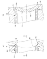
- A) is the principal part enlarged view of FIG. 5
- B) is the BB sectional drawing of (a).
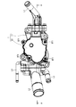
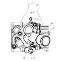
- It is a side view of the flow control valve shown in FIG. It is CC sectional view taken on the line of FIG.
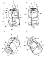
- FIG. 4 is a perspective view of the valve body shown in FIG. 3, and (a) to (d) are views showing a state seen from different viewpoints.
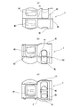
- (A) is an arrow view seen from the D direction of FIG. 10 (a)
- (b) is the EE sectional view taken on the line of FIG. 10 (a).
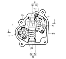
- FIG. 4 is a perspective view of the speed reduction mechanism shown in FIG.
- FIG. 3 It is a top view of the deceleration mechanism shown in FIG. It is the FF sectional view taken on the line of FIG. It is a figure explaining the operating state of the flow control valve concerning the present invention, and (a) is a state where all the discharge ports are out of communication, (b) is a state where only the 1st discharge port is connected, (c) FIG. 4 is a development view of the valve body housing portion showing a state in which the first and second discharge ports are in communication with each other, and FIG. 1 shows a first embodiment of the present invention, where (a) shows a state before the first seal member passes through the first stepped portion, and (b) shows a state where the first seal member passes through the first stepped portion. It is a principal part sectional view shown.
- FIG. 1 It is a perspective view of the valve body showing the other example of the valve body shown in FIG.
- the 2nd Embodiment of this invention is shown, (a) is the state before a 3rd sealing member passes a 3rd level
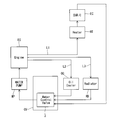
- cooling water circulating system for automotive cooling water
- FIG. 1 to 18 show a first embodiment of a flow control valve according to the present invention.
- the flow rate control valve CV is disposed on the side of the engine EG (specifically, a cylinder head (not shown)). It is arranged between.
- the cooling water pressurized by the water pump WP and guided to the flow control valve CV through the introduction passage L0 is supplied to the heating heat exchanger HT, the oil cooler OC, and the radiator RD via the first to third pipes L1 to L3.
- Each flow is distributed to the side, and each flow rate is controlled.
- the cooling water led to the heating heat exchanger HT is led to the EGR cooler EC and then returned to the engine EG side.
- the flow rate control valve CV is provided with a bypass passage BL that bypasses the introduction passage L0 and directly leads the cooling water to the throttle chamber TC, and the cooling water guided from the engine EG side with the bypass passage BL. Can always be supplied to the throttle chamber TC. Then, the cooling water supplied to the throttle chamber TC is guided to the EGR cooler EC and is returned to the engine EG side through the EGR cooler EC, similarly to the heating heat exchanger HT.
- a symbol WT in FIG. 1 indicates a water temperature sensor.
- the arrangement of the flow control valve CV is not limited to the arrangement immediately after the engine EG, and may be arranged immediately before the engine EG as shown in FIG. 2, for example, depending on the specifications of the mounting target. It can be changed as appropriate. Further, since the distribution to the throttle chamber TC does not correspond to the cooling water flow rate control target as will be described later, the presence or absence of the bypass passage BL also conforms to the specification of the mounting target as shown in FIG. It can be changed accordingly.
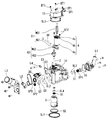
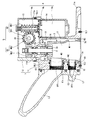
- the flow control valve CV includes a first housing 11 that houses a valve body 3 and an electric motor 4 described later. And a second housing 12 that houses a speed reduction mechanism 5 to be described later, and an end wall 11b of the first housing 11 that separates the first housing 11 and the second housing 12 from each other.
- a rotary shaft 2 rotatably supported by a bearing B1 held by 11b, and a substantially cylindrical valve body 3 fixed to one end of the rotary shaft 2 and rotatably supported in the first housing 11.
- an electric motor 4 disposed in parallel with the valve body 3 in the first housing 11 and used for driving control of the valve body 3, and interposed between the motor output shaft 4 c of the electric motor 4 and the rotary shaft 2.
- a speed reduction mechanism 5 for transmitting by rolling reduction rate is mainly comprised.
- the first housing 11 is cast from an aluminum alloy material, and a substantially cylindrical valve body accommodating portion 13 that is biased toward one end side in the width direction and accommodates the valve body 3 opens toward one end side in the axial direction.
- a substantially cylindrical motor housing portion 14 that is formed and is adjacent to the valve body housing portion 13 and is biased toward the other end in the width direction to house the electric motor 4 is opened toward the other end in the axial direction. It is formed and fixed to a side portion of the engine (not shown) by a bolt (not shown) via a first flange portion 11a formed and extending in the outer peripheral area of the one end side opening of the valve body housing portion 13.
- annular seal member SL1 is interposed between the first flange portion 11a of the first housing 11 and the engine side portion, and the inside of the valve body housing portion 13 is hermetically sealed by the seal member SL1. It is the structure held by.
- the valve body accommodating portion 13 is configured as an inlet 10 which is a main communication port whose one end side opening communicates with the inside of the engine (not shown) and introduces cooling water from the inside of the engine.
- the cooling water is guided to an inner peripheral side passage 17 and an outer peripheral side passage 18 respectively formed on the inner peripheral side and the outer peripheral side of the body 3.
- the peripheral wall of the valve body accommodating portion 13 is provided with a plurality of first to third communication ports which are a plurality of substantially cylindrical communication ports provided for connection to the first to third pipes L1 to L3 at predetermined circumferential positions.
- the discharge ports E1 to E3 are formed to penetrate in the radial direction.
- the 3rd discharge port E3 is arrange
- a build-up used for sliding guidance of first to third seal members S1 to S3 described later is provided at the inner ends of the first to third discharge ports E1 to E3, as shown in FIG. 5 and FIG. 6, a build-up used for sliding guidance of first to third seal members S1 to S3 described later is provided.
- a part 19 is provided.
- the built-up portion 19 has each discharge port E1 so that the inner end surface thereof is substantially flat, that is, the amount of projection of each seal member S1 to S3 from the inner end of each discharge port E1 to E3 is suppressed.
- the first housing 11 is integrally provided. With this construction, the build-up portion 19 can suppress the deformation of the seal members S1 to S3, and the wear of the seal members S1 to S3 caused by the deformation of the seal members S1 to S3 can be suppressed. ing.
- Sealing means for sealing is provided on the inner peripheral side of the first to third discharge ports E1 to E3, when the first to third discharge ports E1 to E3 are closed, the space between the discharge ports E1 to E3 and the valve body 3 is airtight. Sealing means for sealing is provided. This sealing means is accommodated in the inner end side of each of the discharge ports E1 to E3 so as to be movable back and forth, and seals between each of the discharge ports E1 to E3 and the valve body 3 by slidingly contacting the outer peripheral surface of the valve body 3.
- the substantially cylindrical sealing members S1 to S3 and the pipes so as to be seated on the opening edges of the pipes L1 to L3 (the retainer member 16 for the first pipe L1) on the outer ends of the discharge ports E1 to E3.
- a first to a third that are elastically mounted with a predetermined preload between the opening edges of L1 to L3 and the inner end surfaces of the seal members S1 to S3, and bias the seal members S1 to S3 toward the valve body 3 side.
- the coil springs SP1 to SP3 and the inner peripheral surfaces of the discharge ports E1 to E3 and the outer peripheral surfaces of the seal members S1 to S3 are accommodated in recesses formed in the inner peripheral surfaces of the discharge ports E1 to E3.
- the outer peripheral surface of each of the seal members S1 to S3 Each outlet E1 ⁇ E3 by sliding contact with the well-known O-ring SL2 for sealing between the respective seal members S1 ⁇ S3, and a.
- Each of the sealing members S1 to S3 is formed in a first conical taper shape formed in a substantially conical taper shape on the inner peripheral edge on one end side which is the valve body 3 side so as to be in sliding contact with first to third seal sliding contact portions D1 to D3 described later.
- the third seal surfaces S1a to S3a are provided, and on the other end side, flat first to third seating surfaces S1b to S3b used for seating on one end side of each of the coil springs SP1 to SP3 are formed.
- the seal surfaces S1a to S3a have intermediate portions (specifically, points F in FIG. 6A) in the thickness width direction (radial direction) with respect to the seal sliding contact portions D1 to D3. Only the slidable contact, so-called line contact.
- the seal portion F when the valve is closed is configured to be inside the opening widths of first to third openings M1 to M3, which will be described later, in the rotation axis direction of the valve body 3. Yes.
- the other end side of the valve body accommodating portion 13 is such that the inner end faces the outer peripheral passage 18 and the fourth pipe L4 is connected to the outer end.
- a fourth discharge port E4 that guides the cooling water to the throttle chamber TC is formed so as to penetrate the bypass passage BL (see FIG. 1). That is, with this configuration, it is possible to always distribute the cooling water guided to the outer peripheral passage 18 to the throttle chamber TC via the fourth pipe L4 regardless of the rotation phase of the valve body 3 described later. Yes.
- the side of the third discharge port E3 has a valve body accommodating portion 13 in an emergency in which the valve body 3 cannot be driven, for example, when the electric system fails.
- a fail-safe valve 20 that enables communication between the (outer peripheral side passage 18) and the third discharge port E3 is provided, and the supply of cooling water to the radiator RD is ensured even when the valve body 3 is stationary. Thus, overheating of the engine EG can be prevented.
- the fail-safe valve 20 is accommodated in a valve accommodation hole 11c that communicates the outer peripheral side passage 18 and the third pipe L3, and is substantially cylindrical that allows the cooling water to flow in from the inner end side (outer peripheral side passage 18 side). And a wax (not shown) filled therein expands when the cooling water temperature exceeds a predetermined temperature.
- the rod 22a is fixed to the distal end side of the rod 22a of the thermo element 22 so that the rod 22a advances to the outer end side of the flow path component member 21, and the outer end side of the flow path component member 21.
- Coil spring And 4 are composed mainly from.
- the second housing 12 has one end facing the first housing 11 straddling the valve body housing portion 13 and the motor housing portion 14 so as to cover the housing portions 13 and 14. Is fixed to the other end side of the first housing 11 by a plurality of bolts BT1 through a second flange portion 12a that is formed in a concave shape that opens to the outer peripheral area of the one end side opening.
- a speed reduction mechanism accommodating portion 15 that accommodates the speed reduction mechanism 5 is formed between the other end side of the one housing 11.
- the rotating shaft 2 is rotatably supported by the bearing B1 accommodated and disposed in a shaft insertion hole 11d formed through the end wall 11b corresponding to the other end wall of the valve body accommodating portion 13, and is axially supported.
- a valve body 3 is fixed to one end, and a second bevel gear HG2 described later is fixed to the other end so as to be integrally rotatable.
- An annular seal member SL4 is interposed between the outer peripheral surface of the rotary shaft 2 and the inner end side opening edge of the shaft insertion hole 11d, and the seal member SL4 rotates with the shaft insertion hole 11d. The inflow of cooling water from the valve body housing part 13 side to the speed reduction mechanism housing part 15 through the radial clearance with the shaft 2 is suppressed.
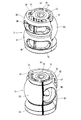
- the valve body 3 is integrally molded from a predetermined synthetic resin material, and as shown in FIGS. 5 and 10 to 12, one end side in the axial direction is cooled water guided from the inlet 10 of the first housing 11. Is formed as an inflow port 3 a for inflow into the inner peripheral side passage 17. On the other hand, the other end side is closed by the end wall 3b, and a plurality of substantially arc-shaped communication ports 3c that allow the inner peripheral side passage 17 and the outer peripheral side passage 18 to communicate with each other are provided in the circumferential direction on the end wall 3b. A notch is formed along.
- a substantially cylindrical shaft fixing portion 3d provided for attachment to the rotary shaft 2 extends along the axial direction at the central portion of the end wall 3b corresponding to the axial center of the valve body 3,
- a metal insert member 3e is integrally formed on the inner peripheral side of the shaft fixing portion 3d so as to be press-fitted and fixed to the rotary shaft 2 via the insert member 3e.
- valve body 3 is brought into sliding contact with the seal members S1 to S3 to provide a substantially spherical seal sliding contact portion (first to third seal sliding contact portions D1 to D3 to be described later) that provide a sealing action when the valve is closed. )
- the discharge ports E1 to E3 are opened and closed by rotating within a predetermined angular range of about 180 ° in the circumferential direction. Yes.
- the valve body 3 is rotationally supported by a bearing B2 that is fitted and held on the inner peripheral side of the introduction port 10 via a bearing portion 3g having a large diameter formed at one end. Has been.
- the valve body 3 is formed in the first axial region X1 on one end side, the second axial region X2 on the other end side, and the two axial regions in forming the seal sliding contact portions D1 to D3. Broadly divided.
- the first and second axial regions X1 and X2 are formed substantially evenly with a substantially intermediate position in the axial direction of the valve body 3 as a boundary.
- at least hole edges of first to third openings M1 to M3 described later are formed in a substantially spherical shape, that is, a curved surface having substantially the same curvature.
- the curvature is configured to be the same as the rotation radius of the valve body 3.
- the first axial direction region X1 is provided over substantially a half circumference, and is provided over a first seal sliding contact portion D1 that is in sliding contact with the first seal member S1, and the remaining substantially half circumference.
- a first seal sliding contact portion D2 that is in sliding contact with the second seal member S2.
- the first seal sliding contact portion D1 is provided with a first opening portion M1 having a long hole shape that is set to have an axial width that overlaps with the first discharge port E1 almost without excess or shortage along the circumferential direction. ing.
- the second seal sliding contact portion D2 is provided with a second opening portion M2 having a long hole shape that is set to have an axial width that overlaps with the second discharge port E2 substantially without excess or deficiency along the circumferential direction. It has been.
- the first opening M1 and the second opening M2 are superposed in different circumferential positions in the first axial region X1 in the rotational axis direction of the valve body 3.
- the valve body 3 is reduced in size in the axial direction.
- Such a superposition arrangement is not limited to the case where the superposition is complete in the axial direction as in the present embodiment.
- the valve body 3 is superposed, and thus the axial direction of the valve body 3 can be shortened by the amount of polymerization.
- the second axial direction area X2 is provided over a half circumference, and is provided over a third sliding contact portion D3 that is in sliding contact with the third seal member S3, and the remaining circumferential area.
- a non-seal slidable contact portion D4 that does not face the third discharge port E3 and does not provide a sealing action by the third seal member S3.
- the third seal sliding contact portion D3 is provided with a long-hole-shaped third opening M3 set in the circumferential direction so as to overlap with the third discharge port E3 without substantial excess or deficiency. ing.
- the non-seal sliding contact portion D4 is provided with an auxiliary suction port M4 having a substantially rectangular shape in plan view along the circumferential direction.
- the auxiliary suction port M4 serves to introduce the cooling water flowing in the outer peripheral side passage 18 into the inner peripheral side passage 17, and in addition to the inlet 3a, the auxiliary suction port M4 also serves as an inner periphery of the cooling water.
- the introduction of the cooling water into the side passage 17 is possible, and a larger amount of cooling water is taken into the inner circumferential side passage 17 and discharged from the discharge ports E1 to E3, thereby reducing the introduction resistance of the cooling water. Yes.
- the non-seal sliding contact portion D4 is a so-called non-use area, unlike the first to third seal sliding contact portions D1 to D3 formed in a substantially spherical shape, the non-seal sliding contact portion D4 is a flat surface having an aspherical shape. Thus, the weight of the valve body 3 and the yield of the material constituting the valve body 3 are reduced.
- first to fourth states shown in FIG. In this order, the communication states with the first to third discharge ports E1 to E3 are switched.
- the first axial region X1 includes a first valve opening region O1 and a second valve opening region O2 used for valve opening by the first and second openings M1 and M2.
- the first valve closing region C1 and the second valve closing region C2 are provided for valve closing by the first and second seal members S1 and S2.
- the second axial region X2 is also used for third valve opening region O3 used for valve opening by the third opening M3 and for valve closing by the third seal member S3.
- a third valve closing region C3 and a non-use region UA constituting the non-seal sliding contact portion D4 are configured.
- first opening M1 which is in the vicinity of the boundary between the first valve opening region O1 and the first valve closing region C1
- first step portion N1 that is recessed radially inward.
- a straight line is formed continuously from one end side to the other end side.
- a concave second step portion N2 that is recessed radially inward is also formed at the circumferential end of the third opening M3 that is in the vicinity of the boundary between the third valve opening region O3 and the third valve closing region C3.
- the first and second axial regions X1 and X2 are notched in a straight line extending from one end side to the other end side.
- the third seal sliding contact portion D3 exceeds 180 ° as shown in FIG. 11 (a). Since the circumferential range is set, the molding of the valve body 3 is performed by dividing the molding die into three parts in order to avoid so-called undercutting. Specifically, as shown in FIGS. 11A and 11B, the first region A1 is formed by the first type, the second region A2 is formed by the second type, and the third region A3 is formed by the third type. Yes.
- a first parting line P1 is formed at the connecting portion between the first mold and the second mold at the center in the width direction of the first step N1, and the second step.
- a second parting line P2 is provided at the connection portion between the second mold and the third mold, and the first mold and the third mold are further connected.
- a third parting line P3 is formed at the connecting portion.
- the first to third molds are molded so that the first to third parting lines P1 to P3 are formed at the respective circumferential positions.
- a pair of contact portions 3 f that serve to restrict the rotation of the valve body 3 are provided at both ends of the third valve closing region C ⁇ b> 3 at the other end of the valve body 3. , 3f are provided.
- the contact portions 3 f and 3 f are provided so as to be able to contact a rotation restricting portion 11 e protruding from the other peripheral wall of the valve body housing portion 13.
- the rotation range of the valve body 3 is regulated within the predetermined angle range by coming into contact with the portion 11e. Since the contact portions 3f and 3f are inevitably provided in accordance with the configuration of the valve body 3, the rotation restricting stopper is separately provided by using the contact portions 3f and 3f. There is no need to provide the flow rate control valve CV, and the cost is reduced.
- the electric motor 4 includes a flange portion 4 b provided at a base end portion of the motor body 4 a in a state where the motor body 4 a is housed in the motor housing portion 14 of the first housing 11.
- the motor output shaft 4c faces into the speed reduction mechanism accommodating portion 15 of the second housing 12 through the opening on the one end side of the motor accommodating portion 14. It is out.
- the electric motor 4 is driven and controlled by a vehicle-mounted electronic controller (not shown), and the valve body 3 is controlled to rotate according to the vehicle operating state, thereby appropriately distributing the cooling water to the radiator RD and the like. Realized.
- the speed reduction mechanism 5 is a drive mechanism composed of two worm gears. As shown in FIGS. 13 to 15, the speed reduction mechanism 5 is linked to a motor output shaft 4c and reduces the rotation of the electric motor 4 to a first worm gear G1. A second worm gear G2 connected to the first worm gear G1 and further decelerating the rotation of the electric motor 4 transmitted through the first worm gear G1 and transmitting it to the rotary shaft 2; The worm gear G2 is disposed so as to be substantially orthogonal to the first worm gear G1.
- the first worm gear G1 is integrally provided on the outer periphery of the motor output shaft 4c.
- the first screw gear WG1 rotates integrally with the motor output shaft 4c, and the first screw gear WG1 substantially parallel to the motor rotation shaft 4c.
- a first inclined tooth which is integrally provided on the outer periphery of one end side of the rotary shaft 30 provided perpendicularly to the first shaft and which decelerates and outputs the rotation of the first screw gear WG1 by meshing with the first screw gear WG1.
- a gear HG1 is integrally provided on the outer periphery of the motor output shaft 4c.
- a first inclined tooth which is integrally provided on the outer periphery of one end side of the rotary shaft 30 provided perpendicularly to the first shaft and which decelerates and outputs the rotation of the first screw gear WG1 by meshing with the first screw gear WG1.
- a gear HG1 which is integrally provided on the outer periphery of one end side of the
- the second worm gear G2 is integrally provided on the outer circumference of the other end of the rotary shaft 30, and is orthogonal to the second screw gear WG2 and a second screw gear WG2 that rotates integrally with the first inclined gear HG1.
- a second inclined tooth which is fixed to the outer periphery of the other end of the rotary shaft 2 arranged in a shape so as to be integrally rotatable and decelerates and outputs the rotation of the second screw gear WG2 by meshing with the second screw gear WG2.
- a gear HG2 is integrally provided on the outer circumference of the other end of the rotary shaft 30, and is orthogonal to the second screw gear WG2 and a second screw gear WG2 that rotates integrally with the first inclined gear HG1.
- a second inclined tooth which is fixed to the outer periphery of the other end of the rotary shaft 2 arranged in a shape so as to be integrally rotatable and decelerates and outputs the rotation of the second screw gear WG2
- the first to third openings M1 to M3 of the valve body 3 are indicated by broken lines, while the first to third discharge ports E1 to E3 of the first housing 11 are hatched.
- the discharge ports E1 to E3 and the openings M1 to M3 can be relatively distinguished by painting and displaying the state in which the two E1 to E3 and M1 to M3 are overlapped and communicated. Shall.
- the flow control valve CV is driven and controlled by the control current from the electronic controller (not shown) that is calculated and output based on the driving state of the vehicle, so that the flow control valve CV corresponds to the driving state of the vehicle.
- the rotational position (phase) of the valve body 3 is controlled so that the relative relationship between the discharge ports E1 to E3 and the openings M1 to M3 is as follows.
- any of the first to third openings M1 to M3 is in a non-communication state with respect to the discharge ports E1 to E3.
- the cooling water is not supplied to any of the heating heat exchanger HT, the oil cooler OC, and the radiator RD.
- any of the first to third openings M1 to M3 is in communication with the discharge ports E1 to E3.
- the cooling water is supplied to all of the heating heat exchanger HT, the oil cooler OC, and the radiator RD, and the first to third discharge ports E1 to E3 and the first to third openings are provided.
- the supply amount changes based on the amount of polymerization with the parts M1 to M3.
- the projecting parting line accompanying the molding is protruded from the sealing region of the valve body, so that the sealing member is slidably contacted with the parting line.
- the sealing surface of the sealing member may be damaged by the ridge.
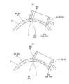
- the concave first and second step portions that are recessed lower than the outer peripheral surfaces of the first to third seal sliding contact portions D1 to D3 that are seal sliding contact surfaces.
- N1 and N2 are provided, and the first and second parting lines P1 and P2 are provided in the stepped portions N1 and N2, so that the seal surfaces S1a to S3a of the seal members S1 to S3 are provided to the parting lines.
- first and second stepped portions N1 and N2 are formed by recesses that are recessed radially inward, the first and second parting lines P1 and P2 are respectively connected to the first and second parting lines P1 and P2. It becomes possible to arrange
- FIG. 1
- the third parting line P3 in the first axial region X1, the third parting line P3 is located at the boundary between the first and second seal sliding contact portions D1 and D2,
- the forward and reverse rotation of the valve body 3 suppresses the inconvenience that each seal surface S1a, S2a passes (crosses) the third parting line P3, and the seal part S1a, S2a is in contact with the third parting line P3. Damage due to sliding contact can be suppressed.
- both the first and second stepped portions N1 and N2 are configured to be connected to the seal sliding contact portions D1 to D3 via smooth curved surfaces, the stepped portions N1 and N2 The formation of corners at the boundary portions of the seal members is suppressed, and damage to the seal surfaces S1a to S3a when the seal members S1 to S3 pass through the step portions N1 and N2 can be more effectively suppressed.
- the circumferential widths of the first and second stepped portions N1 and N2 are set smaller than the circumferential widths of the first to third seal members S1 to S3, as shown in FIG.
- the inconvenience that the seal members S1 to S3 drop off to the first and second stepped portions N1 and N2 is suppressed, and smooth sliding contact of the seal members S1 to S3 can be ensured.
- first and second stepped portions N1 and N2 are provided at the circumferential ends of the first to third openings M1 to M3, the openings M1 to M3 are arranged in the middle. It becomes possible to form integrally, without dividing
- the valve body 3 is good. It is used for manufacturing.
- the seal portions F of the seal surfaces S1a to S3a when the valve is closed are configured to be inside the opening widths of the openings M1 to M3 in the rotation axis direction of the valve body 3. Therefore, even when the seal surfaces S1a to S3a are damaged by sliding contact with the opening edges of the openings M1 to M3, it is possible to maintain a good sealing action by the seal surfaces S1a to S3a.
- a built-up portion 19 is provided at the inner end of each of the discharge ports E1 to E3.
- the portion 19 makes it possible to further narrow the gap between the inner peripheral surface of the one housing 11 and the outer peripheral surface of the valve body 3, and from the inner ends of the discharge ports E1 to E3 of the seal members S1 to S3.
- the amount of protrusion can be suppressed.
- the deformation of each of the seal members S1 to S3 is suppressed, and a stable sealing action by each of the seal members S1 to S3 can be secured, and each of the seal members S1 to S3 (each seal surface) that can be generated by the deformation.
- the wear of S1a to S3a) can be suppressed, and the durability of each of the seal members S1 to S3 can be improved.
- the build-up portion 19 since the build-up portion 19 is formed integrally with the first housing 11, it is not necessary to separately provide the build-up portion 19 and the flow control valve CV is good. It is used for manufacturing. At this time, the build-up portion 19 can be easily formed by casting, and the production of the flow control valve CV can be further improved. Moreover, also when the 1st housing 11 is shape
- FIG. 19 shows a second embodiment of the flow control valve according to the present invention, in which the configurations of the first and second step portions N1, N2 in the first embodiment are changed.
- the first embodiment is the same as the first embodiment except for the configuration associated with the formation of the first and second step portions N1 and N2 and the step portions N1 and N2 described later.
- the first and second stepped portions N1 and N2 are not the concave shape (groove shape) exemplified in the first embodiment, but in the circumferential direction of the seal sliding contact portions D1 to D3.
- the first and second parting lines P1 and P2 are arranged on the stepped portion formed by differentiating the curvatures in the circumferential direction across the stepped portions N1 and N2.
- the first and second stepped portions N1 and N2 change the curvature of the outer peripheral surface of the valve body 3, that is, the curvature before and after the circumferential direction sandwiching the first and second stepped portions N1 and N2. Therefore, it is not necessary to separately form the respective stepped portions N1 and N2, and the valve body 3 can be favorably manufactured and reduced in cost.
- first and second stepped portions N1 and N2 are not formed in a concave shape as in the first embodiment, but are configured by simple steps, as shown in FIG.
- the seal members S1 to S3 pass, at least a part of the first to third seal surfaces S1a to S3a comes into sliding contact with the first and second step portions N1 and N2.
- the slidable contact portion becomes the outer edge of each of the seal surfaces S1a to S2a, and the slidable contact with the seal portion F can be avoided. The damage to the part F can also be suppressed.
- the present invention is not limited to the configuration according to each of the above embodiments.
- the parting lines P1 and P2 are provided at positions where the seal members S1 to S3 are not in sliding contact with the valve body 3. Not only in the form in which the parts N1 and N2 are provided and the parting lines P1 and P2 are arranged in the stepped parts N1 and N2, but also in the unused area obtained by increasing the diameter of the valve body 3, for example.
- a form in which each parting line P1, P2 is arranged (corresponding to the third parting line P3) is also included.
- the stepped portions N1 and N2 are formed in advance in the seal sliding contact portions D1 to D3, and the parting lines P1 and P2 are disposed in the stepped portions N1 and N2.
- a part of each of the parting lines P1 and P2 is placed on the non-sliding portion of each of the sealing members S1 to S3, for example, the parting lines P1 and P2 are disposed on the non-seal sliding contact portion that becomes the unused area.
- the application of the flow rate control valve CV is described as an example of the application of the cooling water to the circulation system.
- the flow rate control valve CV is not limited to the cooling water.
- the present invention can be applied to various fluids.
- the flow control valve is provided in a valve body housing portion configured in a hollow shape, and communicates from the main communication port for introduction or discharge of fluid and the valve body housing portion from the radial direction.
- a housing having a plurality of communication ports for introducing or discharging the fluid in the valve body accommodating portion, and is rotatably supported in the housing, and the polymerization state of the communication ports is in accordance with the rotational position.
- a valve body having a plurality of opening portions that change, and provided between the housing and the valve body, and is in sliding contact with the outer peripheral surface of the valve body to seal between the radial direction of the valve body and the housing.
- a seal member, and at least the communication ports and the openings overlap in a circumferential range of the valve body, and the sliding contact surface of the valve body in sliding contact with the seal member, Radially inward relative to the sliding surface Comprising the step portion is provided as low as.
- the stepped portion is formed by a concave portion recessed inward in the radial direction.
- the circumferential width of the recess is set smaller than the circumferential width of the seal member that passes through the recess.
- the sliding contact surface of the valve body and the recess are connected via a smooth curved surface.
- the recess is provided at a circumferential end of the opening.
- the recess is continuously provided from one end side to the other end side in the rotation axis direction of the valve body.
- the stepped portion is formed by changing the curvature of the outer periphery of the valve body.
- the sliding contact portion of the seal member in a state where the communication port and the opening portion are not overlapped is in the rotation axis direction of the valve body. It is comprised so that it may become an inner side with respect to the opening width of the said opening part.
- a plurality of the openings are provided at different circumferential positions on the outer periphery of the valve body, and at least a part of the openings is the valve body. It is superposed in the direction of the rotation axis.
- a built-up portion provided for sliding guide of the seal member is provided at an inner end of the communication port.
- the build-up portion is formed integrally with the housing.
- valve body is formed by injection molding a synthetic resin material.
- the flow control valve is in sliding contact with the outer peripheral surface of the valve body between the housing and the valve body rotatably supported in the housing.
- a sealing member that seals between the radial direction of the housing and the valve body, and by changing the polymerization state of the communication port that communicates the inside and the outside of the housing and the opening that communicates the inside and the outside of the valve body,
- the flow rate control valve for changing the flow rate of the fluid flowing out from the inner peripheral side of the valve body through the communication port and the opening or flowing into the inner peripheral side of the valve body, out of the circumferential range of the valve body
- a stepped portion that is at least in a range where each of the communication ports and each of the openings overlaps, and is lowered inward in the radial direction with respect to the sliding contact surface on the sliding contact surface of the valve body in which the sealing member is in sliding contact Is provided
- the flow control valve is provided in a hollow valve body housing portion, and is provided with a main communication port for introducing or discharging fluid, and the valve body housing portion.
- a housing having a plurality of communication ports communicating from the radial direction and used for introducing or discharging fluid in the valve body housing portion, and rotatably supported in the housing, and depending on the rotation position, the communication ports,
- the valve body having a plurality of openings in which the polymerization state of the valve body changes, and the radial direction between the valve body and the housing is provided between the housing and the valve body, and is in sliding contact with the outer peripheral surface of the valve body And a parting line is provided at a position where the seal member does not slidably contact with the valve body.
- At least a part of the parting line is provided in a range in which the outer peripheral surface of the valve body and the seal member are in sliding contact in a circumferential range of the valve body.
- At least a part of the parting line slides between an outer peripheral surface of the valve body and the seal member in a circumferential range of the valve body. It is provided in a range that does not touch.
- a surface of the outer periphery of the valve body, in which the outer peripheral surface of the valve body and the seal member are in sliding contact, is formed in a substantially spherical shape,
- the surface on which the outer peripheral surface of the valve body and the seal member do not slide is formed in an aspherical shape.
Landscapes
- Engineering & Computer Science (AREA)
- General Engineering & Computer Science (AREA)
- Mechanical Engineering (AREA)
- Chemical & Material Sciences (AREA)
- Combustion & Propulsion (AREA)
- Multiple-Way Valves (AREA)
- Taps Or Cocks (AREA)
Abstract
Priority Applications (4)
| Application Number | Priority Date | Filing Date | Title |
|---|---|---|---|
| JP2017503416A JP6429988B2 (ja) | 2015-03-03 | 2016-02-19 | 流量制御弁 |
| DE112016001026.5T DE112016001026B4 (de) | 2015-03-03 | 2016-02-19 | Durchfluss-steuerventil |
| US15/555,278 US10927972B2 (en) | 2015-03-03 | 2016-02-19 | Flow rate control valve |
| CN201680013048.3A CN107407432B (zh) | 2015-03-03 | 2016-02-19 | 流量控制阀 |
Applications Claiming Priority (2)
| Application Number | Priority Date | Filing Date | Title |
|---|---|---|---|
| JP2015-040866 | 2015-03-03 | ||
| JP2015040866 | 2015-03-03 |
Publications (1)
| Publication Number | Publication Date |
|---|---|
| WO2016140079A1 true WO2016140079A1 (fr) | 2016-09-09 |
Family
ID=56848199
Family Applications (1)
| Application Number | Title | Priority Date | Filing Date |
|---|---|---|---|
| PCT/JP2016/054795 Ceased WO2016140079A1 (fr) | 2015-03-03 | 2016-02-19 | Vanne de régulation de débit |
Country Status (5)
| Country | Link |
|---|---|
| US (1) | US10927972B2 (fr) |
| JP (1) | JP6429988B2 (fr) |
| CN (1) | CN107407432B (fr) |
| DE (1) | DE112016001026B4 (fr) |
| WO (1) | WO2016140079A1 (fr) |
Cited By (3)
| Publication number | Priority date | Publication date | Assignee | Title |
|---|---|---|---|---|
| WO2018056004A1 (fr) * | 2016-09-21 | 2018-03-29 | 日立オートモティブシステムズ株式会社 | Vanne de régulation de débit et système de refroidissement |
| JP2020112116A (ja) * | 2019-01-15 | 2020-07-27 | トヨタ自動車株式会社 | エンジン冷却装置 |
| WO2025197451A1 (fr) * | 2024-03-21 | 2025-09-25 | 株式会社山田製作所 | Valve de commande |
Families Citing this family (28)
| Publication number | Priority date | Publication date | Assignee | Title |
|---|---|---|---|---|
| DE102018106208A1 (de) * | 2017-06-28 | 2019-01-03 | Yamada Manufacturing Co., Ltd. | Steuerventil |
| DE102018214174A1 (de) | 2017-08-24 | 2019-02-28 | Continental Automotive Systems, Inc. | Kombinationsventil mit mehreren anschlüssen |
| US11168797B2 (en) | 2017-08-24 | 2021-11-09 | Vitesco Technologies USA, LLC | Combination multi-port valve |
| JP7037963B2 (ja) * | 2018-03-08 | 2022-03-17 | 日立Astemo株式会社 | 制御弁 |
| CN115289245B (zh) * | 2018-05-31 | 2025-12-05 | 株式会社电装 | 阀装置 |
| JP7146540B2 (ja) * | 2018-09-13 | 2022-10-04 | 株式会社山田製作所 | 制御バルブ |
| KR102751267B1 (ko) | 2018-11-05 | 2025-01-09 | 현대자동차주식회사 | 다방향 전환 밸브의 실링부재 및 그를 포함하는 다방향 전환 밸브 |
| CN111720591B (zh) * | 2019-03-18 | 2024-06-28 | 罗伯特·博世有限公司 | 分配阀和制冷系统 |
| JP7344663B2 (ja) * | 2019-03-27 | 2023-09-14 | 株式会社山田製作所 | 制御バルブ |
| JP7227050B2 (ja) * | 2019-03-27 | 2023-02-21 | 株式会社山田製作所 | 制御バルブ |
| US11614023B2 (en) * | 2019-03-29 | 2023-03-28 | Hitachi Astemo, Ltd. | Control valve |
| EP3730821B1 (fr) * | 2019-04-23 | 2023-07-05 | Vitesco Technologies GmbH | Vanne multi-voies |
| US11719350B2 (en) | 2019-06-12 | 2023-08-08 | Vitesco Technologies USA, LLC | Coolant flow control module |
| JP7176482B2 (ja) * | 2019-06-17 | 2022-11-22 | 株式会社デンソー | バルブ装置 |
| DE102020201190A1 (de) * | 2019-10-14 | 2021-04-15 | Vitesco Technologies GmbH | Fluidventil |
| JP7419752B2 (ja) * | 2019-11-07 | 2024-01-23 | 株式会社デンソー | バルブ装置 |
| KR20210098087A (ko) | 2020-01-31 | 2021-08-10 | 현대자동차주식회사 | 유량제어밸브 장치 |
| KR20210119659A (ko) * | 2020-03-25 | 2021-10-06 | 현대자동차주식회사 | 유량제어밸브 장치 |
| JP7619136B2 (ja) * | 2021-04-08 | 2025-01-22 | 株式会社デンソー | バルブ装置 |
| US12516743B2 (en) | 2021-06-04 | 2026-01-06 | Vitesco Technologies USA, LLC | Multi-port valve assembly |
| JP7716281B2 (ja) * | 2021-09-08 | 2025-07-31 | Astemo株式会社 | 弁体、流路切換弁、及び自動車用熱媒体システム |
| US11988290B2 (en) | 2021-11-02 | 2024-05-21 | Vitesco Technologies USA, LLC | Coolant flow control valve |
| KR20230068549A (ko) * | 2021-11-11 | 2023-05-18 | 현대자동차주식회사 | 제어 밸브 및 이를 포함하는 차량용 냉각 시스템 |
| US11703135B2 (en) | 2021-12-03 | 2023-07-18 | Vitesco Technologies USA, LLC | Multi-port coolant flow control valve assembly |
| JP7775055B2 (ja) * | 2021-12-13 | 2025-11-25 | 株式会社山田製作所 | 制御バルブ |
| US11885407B1 (en) * | 2022-07-15 | 2024-01-30 | Textron Innovations Inc. | Fluid scavenge system |
| US12359734B2 (en) | 2022-08-25 | 2025-07-15 | Vitesco Technologies USA, LLC | Rotor for multiport coolant flow control valve assembly |
| US12429140B2 (en) * | 2023-10-19 | 2025-09-30 | Schaeffler Technologies AG & Co. KG | Coolant control valve |
Citations (3)
| Publication number | Priority date | Publication date | Assignee | Title |
|---|---|---|---|---|
| JPH01206169A (ja) * | 1988-02-10 | 1989-08-18 | Toto Ltd | 弁構造 |
| JPH0828725A (ja) * | 1994-07-20 | 1996-02-02 | Showa Tekko Kk | 多方弁構造 |
| JP2000130610A (ja) * | 1998-10-22 | 2000-05-12 | Time Engineering Co Ltd | ボールバルブ用樹脂ボール及びその製造方法 |
Family Cites Families (14)
| Publication number | Priority date | Publication date | Assignee | Title |
|---|---|---|---|---|
| US3656711A (en) | 1970-08-17 | 1972-04-18 | Encon Mfg Co | Thermoset plastic ball valve |
| JP2001130610A (ja) * | 1999-11-10 | 2001-05-15 | Toto Kizai Kk | 蓋付き密閉容器 |
| US6488050B1 (en) * | 2001-07-10 | 2002-12-03 | Humphrey Products Company | Pneumatic valve assembly |
| FR2827359B1 (fr) | 2001-07-11 | 2004-11-05 | Valeo Thermique Moteur Sa | Vanne de commande pour un circuit de refroidissement d'un moteur thermique de vehicule automobile |
| WO2008049624A2 (fr) * | 2006-10-27 | 2008-05-02 | Audi Ag | Tiroir rotatif, notamment pour un circuit de réfrigérant d'un moteur à combustion interne présentant plusieurs branches ; sous-ensemble électromécanique |
| DE102007038124B4 (de) * | 2007-08-03 | 2016-01-21 | Südmo Holding GmbH | Doppelsitzventil zur Trennung von Medien |
| FR2956181B1 (fr) * | 2010-02-09 | 2012-02-24 | Defontaine | Dispositif de vanne multivoies pour la circulation de fluides |
| JP5914176B2 (ja) | 2012-05-31 | 2016-05-11 | 株式会社ミクニ | ロータリ式バルブ |
| DE112014000253B4 (de) * | 2013-02-19 | 2019-10-10 | Illinois Tool Works Inc. | Verbrennungsmotor-Fluiddosierventilanordnung |
| WO2014148126A1 (fr) * | 2013-03-21 | 2014-09-25 | 日立オートモティブシステムズ株式会社 | Vanne de régulation de débit |
| CN203309202U (zh) * | 2013-06-20 | 2013-11-27 | 浙江工商职业技术学院 | 一种无潴留多路控制球阀 |
| JP2016023704A (ja) * | 2014-07-18 | 2016-02-08 | 株式会社不二工機 | 流路切換弁 |
| CN104265933B (zh) * | 2014-09-09 | 2017-02-01 | 华英伦科技(宁波)有限公司 | 一种全封闭防老化耐溶蚀长寿命球阀 |
| DE102015218391A1 (de) * | 2015-09-24 | 2017-03-30 | Mahle International Gmbh | Elektrisch angetriebenes Ventil |
-
2016
- 2016-02-19 WO PCT/JP2016/054795 patent/WO2016140079A1/fr not_active Ceased
- 2016-02-19 CN CN201680013048.3A patent/CN107407432B/zh active Active
- 2016-02-19 JP JP2017503416A patent/JP6429988B2/ja active Active
- 2016-02-19 US US15/555,278 patent/US10927972B2/en active Active
- 2016-02-19 DE DE112016001026.5T patent/DE112016001026B4/de active Active
Patent Citations (3)
| Publication number | Priority date | Publication date | Assignee | Title |
|---|---|---|---|---|
| JPH01206169A (ja) * | 1988-02-10 | 1989-08-18 | Toto Ltd | 弁構造 |
| JPH0828725A (ja) * | 1994-07-20 | 1996-02-02 | Showa Tekko Kk | 多方弁構造 |
| JP2000130610A (ja) * | 1998-10-22 | 2000-05-12 | Time Engineering Co Ltd | ボールバルブ用樹脂ボール及びその製造方法 |
Cited By (7)
| Publication number | Priority date | Publication date | Assignee | Title |
|---|---|---|---|---|
| WO2018056004A1 (fr) * | 2016-09-21 | 2018-03-29 | 日立オートモティブシステムズ株式会社 | Vanne de régulation de débit et système de refroidissement |
| JP2018048683A (ja) * | 2016-09-21 | 2018-03-29 | 日立オートモティブシステムズ株式会社 | 流量制御弁および冷却システム |
| US10968809B2 (en) | 2016-09-21 | 2021-04-06 | Hitachi Automotive Systems, Ltd. | Flow control valve and cooling system |
| US11371415B2 (en) | 2016-09-21 | 2022-06-28 | Hitachi Automotive Systems, Ltd. | Flow control valve and cooling system |
| JP2020112116A (ja) * | 2019-01-15 | 2020-07-27 | トヨタ自動車株式会社 | エンジン冷却装置 |
| JP7068205B2 (ja) | 2019-01-15 | 2022-05-16 | トヨタ自動車株式会社 | エンジン冷却装置 |
| WO2025197451A1 (fr) * | 2024-03-21 | 2025-09-25 | 株式会社山田製作所 | Valve de commande |
Also Published As
| Publication number | Publication date |
|---|---|
| JP6429988B2 (ja) | 2018-11-28 |
| DE112016001026T5 (de) | 2017-12-21 |
| US20180051815A1 (en) | 2018-02-22 |
| JPWO2016140079A1 (ja) | 2017-10-05 |
| DE112016001026B4 (de) | 2026-02-19 |
| CN107407432B (zh) | 2019-05-31 |
| CN107407432A (zh) | 2017-11-28 |
| US10927972B2 (en) | 2021-02-23 |
Similar Documents
| Publication | Publication Date | Title |
|---|---|---|
| JP6429988B2 (ja) | 流量制御弁 | |
| JP6837260B2 (ja) | 弁 | |
| JP6501641B2 (ja) | 流量制御弁 | |
| JP6581367B2 (ja) | 流量制御弁 | |
| JP6846083B2 (ja) | 弁及び冷却水の循環システム | |
| US10458562B2 (en) | Control valve | |
| JP6254402B2 (ja) | 流量制御弁 | |
| JP6557044B2 (ja) | 流量制御弁 | |
| JP6630395B2 (ja) | バルブ装置 | |
| US11149627B2 (en) | Cooling-water control valve device | |
| US20200173569A1 (en) | Integrated flow check for water/coolant valves | |
| US11300220B2 (en) | Valve device | |
| US11703136B2 (en) | Control valve | |
| JP6784577B2 (ja) | 制御弁 | |
| JP6742489B2 (ja) | 弁 | |
| JP2019078392A (ja) | 流体制御弁装置 | |
| CN224150218U (zh) | 一种阀芯、多通道阀、热管理系统和车辆 | |
| JP7791699B2 (ja) | 制御バルブ | |
| JP2025187553A (ja) | 弁装置 | |
| CN116261635A (zh) | 阀装置 |
Legal Events
| Date | Code | Title | Description |
|---|---|---|---|
| 121 | Ep: the epo has been informed by wipo that ep was designated in this application |
Ref document number: 16758773 Country of ref document: EP Kind code of ref document: A1 |
|
| ENP | Entry into the national phase |
Ref document number: 2017503416 Country of ref document: JP Kind code of ref document: A |
|
| WWE | Wipo information: entry into national phase |
Ref document number: 15555278 Country of ref document: US |
|
| WWE | Wipo information: entry into national phase |
Ref document number: 112016001026 Country of ref document: DE |
|
| 122 | Ep: pct application non-entry in european phase |
Ref document number: 16758773 Country of ref document: EP Kind code of ref document: A1 |
|
| WWG | Wipo information: grant in national office |
Ref document number: 112016001026 Country of ref document: DE |