WO2016143285A1 - Bouton poussoir et dispositif électronique qui l'utilise - Google Patents
Bouton poussoir et dispositif électronique qui l'utilise Download PDFInfo
- Publication number
- WO2016143285A1 WO2016143285A1 PCT/JP2016/001043 JP2016001043W WO2016143285A1 WO 2016143285 A1 WO2016143285 A1 WO 2016143285A1 JP 2016001043 W JP2016001043 W JP 2016001043W WO 2016143285 A1 WO2016143285 A1 WO 2016143285A1
- Authority
- WO
- WIPO (PCT)
- Prior art keywords
- panel
- arm
- switch
- push button
- axis
- Prior art date
- Legal status (The legal status is an assumption and is not a legal conclusion. Google has not performed a legal analysis and makes no representation as to the accuracy of the status listed.)
- Ceased
Links
Images


Classifications
-
- B—PERFORMING OPERATIONS; TRANSPORTING
- B60—VEHICLES IN GENERAL
- B60R—VEHICLES, VEHICLE FITTINGS, OR VEHICLE PARTS, NOT OTHERWISE PROVIDED FOR
- B60R16/00—Electric or fluid circuits specially adapted for vehicles and not otherwise provided for; Arrangement of elements of electric or fluid circuits specially adapted for vehicles and not otherwise provided for
- B60R16/02—Electric or fluid circuits specially adapted for vehicles and not otherwise provided for; Arrangement of elements of electric or fluid circuits specially adapted for vehicles and not otherwise provided for electric constitutive elements
-
- H—ELECTRICITY
- H01—ELECTRIC ELEMENTS
- H01H—ELECTRIC SWITCHES; RELAYS; SELECTORS; EMERGENCY PROTECTIVE DEVICES
- H01H21/00—Switches operated by an operating part in the form of a pivotable member acted upon directly by a solid body, e.g. by a hand
-
- H—ELECTRICITY
- H01—ELECTRIC ELEMENTS
- H01H—ELECTRIC SWITCHES; RELAYS; SELECTORS; EMERGENCY PROTECTIVE DEVICES
- H01H9/00—Details of switching devices, not covered by groups H01H1/00 - H01H7/00
- H01H9/18—Distinguishing marks on switches, e.g. for indicating switch location in the dark; Adaptation of switches to receive distinguishing marks
Definitions
- the present disclosure relates to a push button, and more particularly, to a push button that indirectly presses a switch and an electronic device using the push button.
- a push button is provided on the in-vehicle device in order to accept the operation to the in-vehicle device. Specifically, an opening is provided in the operation panel arranged on the front surface of the in-vehicle device, and a push button is assembled to the opening (see, for example, Patent Document 1).
- a push button includes a panel that can be pushed down, a board that is arranged in a direction in which the panel is pushed down, a switch mounted thereon, and an arm that is arranged between the board and the panel and has a cantilever shape. And having.
- the arm has a free end and a fixed end, is opposed to the switch at a position closer to the free end than the fixed end, has a projection, and is pushed down by a panel pressing operation.
- the protrusion presses the switch by pushing down the arm. In the panel, the portion closer to the free end than the fixed end is pushed down more than the portion closer to the fixed end than the free end.
- durability can be improved when a switch is not disposed directly below the button.
- FIG. 1 is an external view of a vehicle interior in which an electronic apparatus according to an embodiment is mounted as viewed from the rear.
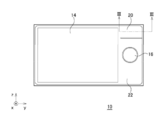
- FIG. 2A is a diagram illustrating an appearance of the surface of the electronic apparatus of the example.
- FIG. 2B is a diagram illustrating an appearance of a side surface of the electronic apparatus according to the embodiment.
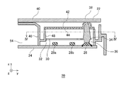
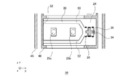
- FIG. 3 is a cross-sectional view (cross-sectional view taken along the line III-III in FIG. 2A) showing the configuration of the push button of the example. 4 is a cross-sectional view taken along line IV-IV in FIG.
- FIG. 5 is a cross-sectional view showing a pressing operation on the panel of FIG.
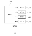
- FIG. 6 is a block diagram illustrating a schematic configuration of the electronic apparatus according to the embodiment.
- the present disclosure has been made in view of such a situation, and provides a technique for improving durability when a switch is not disposed directly below a button.
- An embodiment of the present disclosure relates to an electronic device mounted on a vehicle, for example, a car audio device.
- an electronic device is provided with a push button for receiving an instruction from a user.
- the button is not attached to the panel disposed on the front surface of the electronic device, but the panel can be pressed as a button.
- the switch cannot be arranged directly below the part where the panel is pushed down due to restrictions on the design specifications and the board arrangement position.
- the electronic device particularly the push button provided in the electronic device, is configured as follows.
- FIG. 1 is an external view of a vehicle interior in which an electronic device 10 according to an embodiment of the present disclosure is mounted as viewed from the rear.
- a rectangular coordinate system including an x-axis, a y-axis, and a z-axis is defined.
- the x-axis extends in the front-rear direction of the vehicle
- the y-axis extends in the left-right direction of the vehicle
- the z-axis extends in the up-down direction of the vehicle.
- the positive directions of the x-axis, y-axis, and z-axis are each defined in the direction of the arrow in FIG. 1, and the negative direction is defined in the direction opposite to the arrow.
- the positive direction side of the x-axis may be referred to as “front side”, and the negative direction side of the x-axis may be referred to as “back side”. Further, the positive direction side of the z-axis may be referred to as “upper surface side”, and the negative direction side of the z-axis may be referred to as “lower surface side”.
- the driver's seat 6 is disposed on the positive direction side of the y-axis, and the passenger seat 8 is disposed on the negative direction side of the y-axis.
- the handle 4 is disposed on the negative side of the x axis with respect to the driver seat 6.
- the handle 4 and the driver's seat 6 may be disposed on the negative direction side of the y axis.
- the windshield 2 is arranged on the negative side of the x axis with respect to the handle 4.
- the electronic device 10 is fitted into the center console on the negative direction side of the y axis from the handle 4. The appearance and configuration of the electronic device 10 will be described later.
- the electronic device 10 connects the speaker 12 via a cable (not shown).
- the speaker 12 is disposed inside the left and right doors.
- FIG. 2A and 2B show the appearance of the electronic device 10.
- 2A is an external view of the surface of the electronic device 10
- FIG. 2B is an external view of the side surface of the electronic device 10.
- the monitor 14 is arranged on the yz plane on the surface of the electronic device 10.
- a panel 22 is disposed so as to surround the monitor 14.
- a knob 16 is attached to the panel 22.
- the knob 16 is rotatable in the yz plane.
- the user inputs an instruction to the electronic device 10 by rotating the knob 16.
- the knob 16 is configured to be able to be pushed down in the negative direction of the x-axis, and the user may input an instruction to the electronic device 10 by pushing down the knob 16.
- Push buttons 20 are formed at the positive corners of the z-axis and y-axis of the panel 22. The user inputs an instruction to the electronic device 10 by pressing down the panel 22 of the push button 20.
- FIG. 3 is a cross-sectional view showing the configuration of the push button 20 (cross-sectional view taken along the line III-III in FIG. 2A).
- 4 is a cross-sectional view taken along line IV-IV in FIG.
- the push button 20 includes a panel 22, a substrate 24, an arm 30, an elastic part 42, a diffusion plate 44, a first support part 46, and a second support part 48.
- the panel 22 includes a facing position 38 and a fulcrum 40
- the substrate 24 includes a switch 26, a first light emitting element 28a and a second light emitting element 28b, which are collectively referred to as a light emitting element 28, an arm 30 having a fixed end 32, a free end.
- the end 34, the protrusion 36, the first arm 50, and the second arm 52 are included.
- the panel 22 and the substrate 24 are formed in a planar shape in the yz plane, and are spaced apart from and substantially parallel to the x direction.
- “substantially” means to include an error range.
- the first support portion 46 is provided from the substrate 24 to the panel 22 along the x axis, and is bent near the panel 22 and is provided along the negative direction of the y axis.
- the panel 22 is fixed to the first support portion 46. Therefore, the first support portion 46 supports the panel 22.
- the first support portion 46 branches to the positive side of the y axis at a position closer to the substrate 24 than half of the distance from the substrate 24 to the panel 22.
- the branched portion is the second support portion 48.
- the panel 22 is fixed to the first support portion 46 on the negative direction side of the y-axis.
- the panel 22 has a configuration that can be pushed down in the negative direction of the x axis on the positive direction side of the y axis from the portion fixed to the first support portion 46.
- substrate 24 is arrange
- the substrate 24 mounts a switch 26 and two light emitting elements 28. Specifically, the first light emitting element 28a, the second light emitting element 28b, and the switch 26 are arranged in a line from the negative direction of the y-axis to the positive direction.
- an instruction to the electronic device 10 is input. Since a known technique may be used for the switch 26 and the light emitting element 28, description thereof is omitted here.
- the arm 30 is disposed between the substrate 24 and the panel 22 in the x-axis direction.
- the arm 30 has a cantilever shape. Specifically, the arm 30 is fixed to the second support portion 48 at the end in the negative direction of the y-axis. The portion to be fixed is the fixed end 32. Further, the end in the positive direction of the y-axis of the arm 30 is a free end 34.
- the arm 30 faces the switch 26 at a position closer to the free end 34 than to the fixed end 32.
- a protrusion 36 is formed at a position facing the switch 26 of the arm 30, and a portion of the arm 30 facing the switch 26 is pushed down in the negative direction of the x axis by the pushing operation of the panel 22. That is, the arm 30 is opposed to the switch 26 at a position closer to the free end 34 than the fixed end 32, and a projection 36 is formed. The arm 30 is pushed down by pushing down the panel 22.
- the protrusion 36 extends to the vicinity of the panel 22 in the positive direction of the x axis and extends to the vicinity of the switch 26 in the negative direction of the x axis.
- the protrusion 36 presses the switch 26 by pushing down the arm 30.
- An elastic part 42 and a diffusion plate 44 are disposed between the arm 30 and the panel 22.
- the diffusion plate 44 diffuses the light emitted from the light emitting element 28.
- the elastic portion 42 is formed of rubber or the like, and is disposed between the panel 22 and the protruding portion 36 in order to reduce wear of the protruding portion 36 due to the panel 22. Further, the elastic portion 42 is disposed on the diffusion plate 44 so as to avoid a light path from the light emitting element 28 toward the panel 22.
- the elastic portion 42 has a portion that is separated in the z-axis direction on the yz plane, and each of the elastic portions 42 is disposed along the y-axis direction. Therefore, the elastic portion 42 is not formed at a position above the light emitting element 28 (positive direction of the x axis), and light from the light emitting element 28 can be transmitted.
- the first arm 50 and the second arm 52 in the arm 30 are arranged along the y-axis direction while being separated from each other in the z-axis direction on the yz plane. Further, the first arm 50 and the second arm 52 are connected at the protrusion 36 on the free end 34 side.
- the first light emitting element 28a and the second light emitting element 28b are arranged between the first arm 50 and the second arm 52 in the yz plane. Therefore, the first light emitting element 28 a and the second light emitting element 28 b face the panel 22 without being blocked by the first arm 50 and the second arm 52.
- the first arm 50 and the second arm 52 are disposed so as to avoid the light path from the light emitting element 28 toward the panel 22.
- the panel 22 has a fulcrum 40 on the fixed end 32 side of the arm 30 (a portion closer to the fixed end 32 than the free end 34).
- the panel 22 is fixed to the first support portion 46 on the negative direction side of the y axis with respect to the fulcrum 40, and the panel 22 is not fixed on the positive direction side of the y axis with respect to the fulcrum 40. Therefore, as shown in FIG. 5, the pressing amount of the panel 22 is larger at a position closer to the free end 34 of the arm 30 than to the fulcrum 40. That is, in the panel 22, the portion closer to the free end 34 than the fixed end 32 is pushed down more than the portion closer to the fixed end 32 than the free end 34.
- the fulcrum 40 of the panel 22 and the fixed end 32 of the arm 30 are provided in the same direction with respect to the protrusion 36, the panel 22 and the arm 30 are the same when the panel 22 is pushed down. Pushed down in the direction. Therefore, an increase in friction between the panel 22 and the switch 26 is suppressed.
- the position facing the switch 26 is indicated as a facing position 38.
- the distance between the facing position 38 and the fulcrum 40 is the first distance and the distance between the position where the protrusion 36 is formed on the arm 30 and the fixed end 32 is the second distance, the second distance is more than the first distance. Shortened.
- the fixed end 32 and the first support portion 46 are disposed on the positive side of the y-axis with respect to the fulcrum 40. Therefore, the circuit region 54 provided on the negative direction side of the y-axis can be made wider than the first support portion 46.
- FIG. 6 is a block diagram illustrating a schematic configuration of the electronic device 10.
- the electronic device 10 includes a processing unit 100, a monitor 14, a speaker 12, a push button 20, and a knob 16.
- the push button 20 receives an instruction from the user.
- An example of the instruction is an instruction to reproduce sound in the processing unit 100.
- the push button 20 outputs the received instruction to the processing unit 100.
- the knob 16 also receives instructions from the user.
- An example of the instruction is an instruction for selecting a sound to be reproduced in the processing unit 100.
- the processing unit 100 executes a predetermined process. As described above, when the electronic device 10 is a car audio device, the predetermined processing corresponds to sound reproduction, information generation, and the like.
- the processing unit 100 executes a process according to a pressing operation on the push button 20 and also executes a process according to a rotation operation on the knob 16.
- Speaker 12 and monitor 14 are arranged as shown in FIG.
- the speaker 12 outputs the sound reproduced by the processing unit 100.
- the monitor 14 displays information generated in the processing unit 100.
- This configuration can be realized in terms of hardware by a CPU, memory, or other LSI of any computer, and in terms of software, it can be realized by a program loaded in the memory, but here it is realized by their cooperation.
- Draw functional blocks Accordingly, those skilled in the art will understand that these functional blocks can be realized in various forms only by hardware, or by a combination of hardware and software.
- an arm having a protrusion for pressing the switch is disposed between the board on which the switch is mounted and the panel. Even when the is not arranged, the switch can be pressed. Moreover, since the fulcrum of the panel and the fixed end of the arm are arranged in the same direction with respect to the switch, the panel and the arm can be pushed down in the same direction. Further, since the amount of pressing down the panel is larger on the free end side than on the fixed end side of the arm, the panel and the arm can be pushed down in the same direction.
- the panel and arm can be pushed down in the same direction, the friction between the protrusion and the panel can be reduced. Moreover, since the friction between a projection part and a panel is reduced, deterioration of components can be suppressed. Moreover, since deterioration of components is suppressed, durability can be improved. Moreover, since the friction between a projection part and a panel is reduced, an operation load can be reduced. Further, since the operation load is reduced, the durability can be improved. In addition, since the arm is disposed so as to avoid the light path from the light emitting element to the panel, the visibility by the user can be improved.
- the electronic device 10 is configured as a car audio device.
- the electronic device 10 is not limited to a car audio device, and may be configured as other in-vehicle devices such as a car navigation device and an air conditioner device.
- the electronic device 10 is not limited to an in-vehicle device, and may be configured as a home electronic device or a business electronic device.
- a function other than the interface function of the car audio function may be executed. According to this modification, the application range can be expanded.
- the present disclosure can be applied to an electronic device mounted on a vehicle or the like, and can improve durability particularly in an electronic device having a high design property.
Landscapes
- Engineering & Computer Science (AREA)
- Mechanical Engineering (AREA)
- Rotary Switch, Piano Key Switch, And Lever Switch (AREA)
- Switch Cases, Indication, And Locking (AREA)
Abstract
L'invention concerne un bouton-poussoir qui possède un panneau à pousser vers le bas, un substrat sur lequel est monté un commutateur et qui est positionné dans la direction d'appui vers le bas du panneau, et un bras positionné entre le substrat et le panneau. Le bras a une forme en porte-à-faux, avec une extrémité libre et une extrémité fixe. Une position sur le bras plus proche de son extrémité libre que de son extrémité fixe fait face au commutateur, une section en saillie étant formée dessus. Le bras est également poussé vers le bas par l'opération d'appui vers le bas du panneau. Le bras, lorsqu'il est poussé vers le bas, amène la section en saillie à appliquer une pression sur le commutateur. La section du panneau plus proche de l'extrémité libre que de l'extrémité fixe est poussée vers le bas à un plus grand degré que la section plus proche de l'extrémité fixe que de l'extrémité libre.
Priority Applications (2)
| Application Number | Priority Date | Filing Date | Title |
|---|---|---|---|
| JP2017504847A JPWO2016143285A1 (ja) | 2015-03-11 | 2016-02-26 | 押し釦およびそれを利用した電子機器 |
| CN201680013423.4A CN107408471A (zh) | 2015-03-11 | 2016-02-26 | 按钮以及利用该按钮的电子设备 |
Applications Claiming Priority (2)
| Application Number | Priority Date | Filing Date | Title |
|---|---|---|---|
| JP2015048723 | 2015-03-11 | ||
| JP2015-048723 | 2015-03-11 |
Publications (1)
| Publication Number | Publication Date |
|---|---|
| WO2016143285A1 true WO2016143285A1 (fr) | 2016-09-15 |
Family
ID=56879093
Family Applications (1)
| Application Number | Title | Priority Date | Filing Date |
|---|---|---|---|
| PCT/JP2016/001043 Ceased WO2016143285A1 (fr) | 2015-03-11 | 2016-02-26 | Bouton poussoir et dispositif électronique qui l'utilise |
Country Status (3)
| Country | Link |
|---|---|
| JP (1) | JPWO2016143285A1 (fr) |
| CN (1) | CN107408471A (fr) |
| WO (1) | WO2016143285A1 (fr) |
Citations (3)
| Publication number | Priority date | Publication date | Assignee | Title |
|---|---|---|---|---|
| JPH0295377U (fr) * | 1989-01-13 | 1990-07-30 | ||
| JP2010010148A (ja) * | 2009-10-13 | 2010-01-14 | Panasonic Corp | スイッチ入力装置 |
| JP2013178938A (ja) * | 2012-02-28 | 2013-09-09 | Aiphone Co Ltd | 電子機器の操作ボタン構造 |
Family Cites Families (2)
| Publication number | Priority date | Publication date | Assignee | Title |
|---|---|---|---|---|
| AU2006312851A1 (en) * | 2005-11-11 | 2007-05-18 | Linak A/S | Electric hand control, especially for electrically adjustable hospital and care beds |
| JP5292964B2 (ja) * | 2008-07-16 | 2013-09-18 | ヤマハ株式会社 | 透光式操作子ユニット |
-
2016
- 2016-02-26 CN CN201680013423.4A patent/CN107408471A/zh active Pending
- 2016-02-26 JP JP2017504847A patent/JPWO2016143285A1/ja active Pending
- 2016-02-26 WO PCT/JP2016/001043 patent/WO2016143285A1/fr not_active Ceased
Patent Citations (3)
| Publication number | Priority date | Publication date | Assignee | Title |
|---|---|---|---|---|
| JPH0295377U (fr) * | 1989-01-13 | 1990-07-30 | ||
| JP2010010148A (ja) * | 2009-10-13 | 2010-01-14 | Panasonic Corp | スイッチ入力装置 |
| JP2013178938A (ja) * | 2012-02-28 | 2013-09-09 | Aiphone Co Ltd | 電子機器の操作ボタン構造 |
Also Published As
| Publication number | Publication date |
|---|---|
| CN107408471A (zh) | 2017-11-28 |
| JPWO2016143285A1 (ja) | 2017-12-21 |
Similar Documents
| Publication | Publication Date | Title |
|---|---|---|
| CN113170243A (zh) | 输入设备 | |
| KR101103231B1 (ko) | 휴대폰의 기능을 차량에 적용하기 위한 연결장치 | |
| KR102349641B1 (ko) | 차량의 터치패널 컨트롤러 조립체 | |
| CN102467901B (zh) | 键盘装置 | |
| WO2016125483A1 (fr) | Panneau tactile avec bouton-poussoir | |
| JPWO2018216694A1 (ja) | 車載装置 | |
| JP5883318B2 (ja) | 車両用スイッチノブの取り付け構造 | |
| JPWO2016143285A1 (ja) | 押し釦およびそれを利用した電子機器 | |
| JP6732671B2 (ja) | パネル装置およびパネル装置の組立方法 | |
| JP7195065B2 (ja) | 車載機器の取付構造 | |
| JPWO2014038085A1 (ja) | 電子機器の仮固定構造 | |
| US11964562B2 (en) | Operation panel | |
| WO2017164001A1 (fr) | Dispositif à panneau tactile | |
| JP6325312B2 (ja) | 電子機器 | |
| EP1666312A1 (fr) | Panneau pour intérieur véhicule absorbant un impact | |
| JP4513680B2 (ja) | 車載機器 | |
| JP6383306B2 (ja) | 押圧操作装置 | |
| US20250076917A1 (en) | Lever switch, display device, and in-vehicle device | |
| JP2020055328A (ja) | 操作入力装置 | |
| JP2018205882A (ja) | 入力装置および入力システム | |
| JP2019139296A (ja) | 操作表示装置 | |
| JP2023160382A (ja) | 車載用揺動スイッチユニット | |
| JP2022122353A (ja) | 操作装置、車載装置 | |
| JP6648735B2 (ja) | 操作装置 | |
| JP2015215989A (ja) | 操作装置 |
Legal Events
| Date | Code | Title | Description |
|---|---|---|---|
| 121 | Ep: the epo has been informed by wipo that ep was designated in this application |
Ref document number: 16761263 Country of ref document: EP Kind code of ref document: A1 |
|
| ENP | Entry into the national phase |
Ref document number: 2017504847 Country of ref document: JP Kind code of ref document: A |
|
| NENP | Non-entry into the national phase |
Ref country code: DE |
|
| 122 | Ep: pct application non-entry in european phase |
Ref document number: 16761263 Country of ref document: EP Kind code of ref document: A1 |