WO2016143285A1 - 押し釦およびそれを利用した電子機器 - Google Patents
押し釦およびそれを利用した電子機器 Download PDFInfo
- Publication number
- WO2016143285A1 WO2016143285A1 PCT/JP2016/001043 JP2016001043W WO2016143285A1 WO 2016143285 A1 WO2016143285 A1 WO 2016143285A1 JP 2016001043 W JP2016001043 W JP 2016001043W WO 2016143285 A1 WO2016143285 A1 WO 2016143285A1
- Authority
- WO
- WIPO (PCT)
- Prior art keywords
- panel
- arm
- switch
- push button
- axis
- Prior art date
- Legal status (The legal status is an assumption and is not a legal conclusion. Google has not performed a legal analysis and makes no representation as to the accuracy of the status listed.)
- Ceased
Links
Images



Classifications
-
- B—PERFORMING OPERATIONS; TRANSPORTING
- B60—VEHICLES IN GENERAL
- B60R—VEHICLES, VEHICLE FITTINGS, OR VEHICLE PARTS, NOT OTHERWISE PROVIDED FOR
- B60R16/00—Electric or fluid circuits specially adapted for vehicles and not otherwise provided for; Arrangement of elements of electric or fluid circuits specially adapted for vehicles and not otherwise provided for
- B60R16/02—Electric or fluid circuits specially adapted for vehicles and not otherwise provided for; Arrangement of elements of electric or fluid circuits specially adapted for vehicles and not otherwise provided for electric constitutive elements
-
- H—ELECTRICITY
- H01—ELECTRIC ELEMENTS
- H01H—ELECTRIC SWITCHES; RELAYS; SELECTORS; EMERGENCY PROTECTIVE DEVICES
- H01H21/00—Switches operated by an operating part in the form of a pivotable member acted upon directly by a solid body, e.g. by a hand
-
- H—ELECTRICITY
- H01—ELECTRIC ELEMENTS
- H01H—ELECTRIC SWITCHES; RELAYS; SELECTORS; EMERGENCY PROTECTIVE DEVICES
- H01H9/00—Details of switching devices, not covered by groups H01H1/00 - H01H7/00
- H01H9/18—Distinguishing marks on switches, e.g. for indicating switch location in the dark; Adaptation of switches to receive distinguishing marks
Definitions
- the present disclosure relates to a push button, and more particularly, to a push button that indirectly presses a switch and an electronic device using the push button.
- a push button is provided on the in-vehicle device in order to accept the operation to the in-vehicle device. Specifically, an opening is provided in the operation panel arranged on the front surface of the in-vehicle device, and a push button is assembled to the opening (see, for example, Patent Document 1).
- a push button includes a panel that can be pushed down, a board that is arranged in a direction in which the panel is pushed down, a switch mounted thereon, and an arm that is arranged between the board and the panel and has a cantilever shape. And having.
- the arm has a free end and a fixed end, is opposed to the switch at a position closer to the free end than the fixed end, has a projection, and is pushed down by a panel pressing operation.
- the protrusion presses the switch by pushing down the arm. In the panel, the portion closer to the free end than the fixed end is pushed down more than the portion closer to the fixed end than the free end.
- durability can be improved when a switch is not disposed directly below the button.
- FIG. 1 is an external view of a vehicle interior in which an electronic apparatus according to an embodiment is mounted as viewed from the rear.
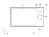
- FIG. 2A is a diagram illustrating an appearance of the surface of the electronic apparatus of the example.
- FIG. 2B is a diagram illustrating an appearance of a side surface of the electronic apparatus according to the embodiment.
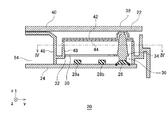
- FIG. 3 is a cross-sectional view (cross-sectional view taken along the line III-III in FIG. 2A) showing the configuration of the push button of the example. 4 is a cross-sectional view taken along line IV-IV in FIG.
- FIG. 5 is a cross-sectional view showing a pressing operation on the panel of FIG.
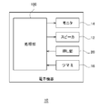
- FIG. 6 is a block diagram illustrating a schematic configuration of the electronic apparatus according to the embodiment.
- the present disclosure has been made in view of such a situation, and provides a technique for improving durability when a switch is not disposed directly below a button.
- An embodiment of the present disclosure relates to an electronic device mounted on a vehicle, for example, a car audio device.
- an electronic device is provided with a push button for receiving an instruction from a user.
- the button is not attached to the panel disposed on the front surface of the electronic device, but the panel can be pressed as a button.
- the switch cannot be arranged directly below the part where the panel is pushed down due to restrictions on the design specifications and the board arrangement position.
- the electronic device particularly the push button provided in the electronic device, is configured as follows.
- FIG. 1 is an external view of a vehicle interior in which an electronic device 10 according to an embodiment of the present disclosure is mounted as viewed from the rear.
- a rectangular coordinate system including an x-axis, a y-axis, and a z-axis is defined.
- the x-axis extends in the front-rear direction of the vehicle
- the y-axis extends in the left-right direction of the vehicle
- the z-axis extends in the up-down direction of the vehicle.
- the positive directions of the x-axis, y-axis, and z-axis are each defined in the direction of the arrow in FIG. 1, and the negative direction is defined in the direction opposite to the arrow.
- the positive direction side of the x-axis may be referred to as “front side”, and the negative direction side of the x-axis may be referred to as “back side”. Further, the positive direction side of the z-axis may be referred to as “upper surface side”, and the negative direction side of the z-axis may be referred to as “lower surface side”.
- the driver's seat 6 is disposed on the positive direction side of the y-axis, and the passenger seat 8 is disposed on the negative direction side of the y-axis.
- the handle 4 is disposed on the negative side of the x axis with respect to the driver seat 6.
- the handle 4 and the driver's seat 6 may be disposed on the negative direction side of the y axis.
- the windshield 2 is arranged on the negative side of the x axis with respect to the handle 4.
- the electronic device 10 is fitted into the center console on the negative direction side of the y axis from the handle 4. The appearance and configuration of the electronic device 10 will be described later.
- the electronic device 10 connects the speaker 12 via a cable (not shown).
- the speaker 12 is disposed inside the left and right doors.
- FIG. 2A and 2B show the appearance of the electronic device 10.
- 2A is an external view of the surface of the electronic device 10
- FIG. 2B is an external view of the side surface of the electronic device 10.
- the monitor 14 is arranged on the yz plane on the surface of the electronic device 10.
- a panel 22 is disposed so as to surround the monitor 14.
- a knob 16 is attached to the panel 22.
- the knob 16 is rotatable in the yz plane.
- the user inputs an instruction to the electronic device 10 by rotating the knob 16.
- the knob 16 is configured to be able to be pushed down in the negative direction of the x-axis, and the user may input an instruction to the electronic device 10 by pushing down the knob 16.
- Push buttons 20 are formed at the positive corners of the z-axis and y-axis of the panel 22. The user inputs an instruction to the electronic device 10 by pressing down the panel 22 of the push button 20.
- FIG. 3 is a cross-sectional view showing the configuration of the push button 20 (cross-sectional view taken along the line III-III in FIG. 2A).
- 4 is a cross-sectional view taken along line IV-IV in FIG.
- the push button 20 includes a panel 22, a substrate 24, an arm 30, an elastic part 42, a diffusion plate 44, a first support part 46, and a second support part 48.
- the panel 22 includes a facing position 38 and a fulcrum 40
- the substrate 24 includes a switch 26, a first light emitting element 28a and a second light emitting element 28b, which are collectively referred to as a light emitting element 28, an arm 30 having a fixed end 32, a free end.
- the end 34, the protrusion 36, the first arm 50, and the second arm 52 are included.
- the panel 22 and the substrate 24 are formed in a planar shape in the yz plane, and are spaced apart from and substantially parallel to the x direction.
- “substantially” means to include an error range.
- the first support portion 46 is provided from the substrate 24 to the panel 22 along the x axis, and is bent near the panel 22 and is provided along the negative direction of the y axis.
- the panel 22 is fixed to the first support portion 46. Therefore, the first support portion 46 supports the panel 22.
- the first support portion 46 branches to the positive side of the y axis at a position closer to the substrate 24 than half of the distance from the substrate 24 to the panel 22.
- the branched portion is the second support portion 48.
- the panel 22 is fixed to the first support portion 46 on the negative direction side of the y-axis.
- the panel 22 has a configuration that can be pushed down in the negative direction of the x axis on the positive direction side of the y axis from the portion fixed to the first support portion 46.
- substrate 24 is arrange
- the substrate 24 mounts a switch 26 and two light emitting elements 28. Specifically, the first light emitting element 28a, the second light emitting element 28b, and the switch 26 are arranged in a line from the negative direction of the y-axis to the positive direction.
- an instruction to the electronic device 10 is input. Since a known technique may be used for the switch 26 and the light emitting element 28, description thereof is omitted here.
- the arm 30 is disposed between the substrate 24 and the panel 22 in the x-axis direction.
- the arm 30 has a cantilever shape. Specifically, the arm 30 is fixed to the second support portion 48 at the end in the negative direction of the y-axis. The portion to be fixed is the fixed end 32. Further, the end in the positive direction of the y-axis of the arm 30 is a free end 34.
- the arm 30 faces the switch 26 at a position closer to the free end 34 than to the fixed end 32.
- a protrusion 36 is formed at a position facing the switch 26 of the arm 30, and a portion of the arm 30 facing the switch 26 is pushed down in the negative direction of the x axis by the pushing operation of the panel 22. That is, the arm 30 is opposed to the switch 26 at a position closer to the free end 34 than the fixed end 32, and a projection 36 is formed. The arm 30 is pushed down by pushing down the panel 22.
- the protrusion 36 extends to the vicinity of the panel 22 in the positive direction of the x axis and extends to the vicinity of the switch 26 in the negative direction of the x axis.
- the protrusion 36 presses the switch 26 by pushing down the arm 30.
- An elastic part 42 and a diffusion plate 44 are disposed between the arm 30 and the panel 22.
- the diffusion plate 44 diffuses the light emitted from the light emitting element 28.
- the elastic portion 42 is formed of rubber or the like, and is disposed between the panel 22 and the protruding portion 36 in order to reduce wear of the protruding portion 36 due to the panel 22. Further, the elastic portion 42 is disposed on the diffusion plate 44 so as to avoid a light path from the light emitting element 28 toward the panel 22.
- the elastic portion 42 has a portion that is separated in the z-axis direction on the yz plane, and each of the elastic portions 42 is disposed along the y-axis direction. Therefore, the elastic portion 42 is not formed at a position above the light emitting element 28 (positive direction of the x axis), and light from the light emitting element 28 can be transmitted.
- the first arm 50 and the second arm 52 in the arm 30 are arranged along the y-axis direction while being separated from each other in the z-axis direction on the yz plane. Further, the first arm 50 and the second arm 52 are connected at the protrusion 36 on the free end 34 side.
- the first light emitting element 28a and the second light emitting element 28b are arranged between the first arm 50 and the second arm 52 in the yz plane. Therefore, the first light emitting element 28 a and the second light emitting element 28 b face the panel 22 without being blocked by the first arm 50 and the second arm 52.
- the first arm 50 and the second arm 52 are disposed so as to avoid the light path from the light emitting element 28 toward the panel 22.
- the panel 22 has a fulcrum 40 on the fixed end 32 side of the arm 30 (a portion closer to the fixed end 32 than the free end 34).
- the panel 22 is fixed to the first support portion 46 on the negative direction side of the y axis with respect to the fulcrum 40, and the panel 22 is not fixed on the positive direction side of the y axis with respect to the fulcrum 40. Therefore, as shown in FIG. 5, the pressing amount of the panel 22 is larger at a position closer to the free end 34 of the arm 30 than to the fulcrum 40. That is, in the panel 22, the portion closer to the free end 34 than the fixed end 32 is pushed down more than the portion closer to the fixed end 32 than the free end 34.
- the fulcrum 40 of the panel 22 and the fixed end 32 of the arm 30 are provided in the same direction with respect to the protrusion 36, the panel 22 and the arm 30 are the same when the panel 22 is pushed down. Pushed down in the direction. Therefore, an increase in friction between the panel 22 and the switch 26 is suppressed.
- the position facing the switch 26 is indicated as a facing position 38.
- the distance between the facing position 38 and the fulcrum 40 is the first distance and the distance between the position where the protrusion 36 is formed on the arm 30 and the fixed end 32 is the second distance, the second distance is more than the first distance. Shortened.
- the fixed end 32 and the first support portion 46 are disposed on the positive side of the y-axis with respect to the fulcrum 40. Therefore, the circuit region 54 provided on the negative direction side of the y-axis can be made wider than the first support portion 46.
- FIG. 6 is a block diagram illustrating a schematic configuration of the electronic device 10.
- the electronic device 10 includes a processing unit 100, a monitor 14, a speaker 12, a push button 20, and a knob 16.
- the push button 20 receives an instruction from the user.
- An example of the instruction is an instruction to reproduce sound in the processing unit 100.
- the push button 20 outputs the received instruction to the processing unit 100.
- the knob 16 also receives instructions from the user.
- An example of the instruction is an instruction for selecting a sound to be reproduced in the processing unit 100.
- the processing unit 100 executes a predetermined process. As described above, when the electronic device 10 is a car audio device, the predetermined processing corresponds to sound reproduction, information generation, and the like.
- the processing unit 100 executes a process according to a pressing operation on the push button 20 and also executes a process according to a rotation operation on the knob 16.
- Speaker 12 and monitor 14 are arranged as shown in FIG.
- the speaker 12 outputs the sound reproduced by the processing unit 100.
- the monitor 14 displays information generated in the processing unit 100.
- This configuration can be realized in terms of hardware by a CPU, memory, or other LSI of any computer, and in terms of software, it can be realized by a program loaded in the memory, but here it is realized by their cooperation.
- Draw functional blocks Accordingly, those skilled in the art will understand that these functional blocks can be realized in various forms only by hardware, or by a combination of hardware and software.
- an arm having a protrusion for pressing the switch is disposed between the board on which the switch is mounted and the panel. Even when the is not arranged, the switch can be pressed. Moreover, since the fulcrum of the panel and the fixed end of the arm are arranged in the same direction with respect to the switch, the panel and the arm can be pushed down in the same direction. Further, since the amount of pressing down the panel is larger on the free end side than on the fixed end side of the arm, the panel and the arm can be pushed down in the same direction.
- the panel and arm can be pushed down in the same direction, the friction between the protrusion and the panel can be reduced. Moreover, since the friction between a projection part and a panel is reduced, deterioration of components can be suppressed. Moreover, since deterioration of components is suppressed, durability can be improved. Moreover, since the friction between a projection part and a panel is reduced, an operation load can be reduced. Further, since the operation load is reduced, the durability can be improved. In addition, since the arm is disposed so as to avoid the light path from the light emitting element to the panel, the visibility by the user can be improved.
- the electronic device 10 is configured as a car audio device.
- the electronic device 10 is not limited to a car audio device, and may be configured as other in-vehicle devices such as a car navigation device and an air conditioner device.
- the electronic device 10 is not limited to an in-vehicle device, and may be configured as a home electronic device or a business electronic device.
- a function other than the interface function of the car audio function may be executed. According to this modification, the application range can be expanded.
- the present disclosure can be applied to an electronic device mounted on a vehicle or the like, and can improve durability particularly in an electronic device having a high design property.
Landscapes
- Engineering & Computer Science (AREA)
- Mechanical Engineering (AREA)
- Rotary Switch, Piano Key Switch, And Lever Switch (AREA)
- Switch Cases, Indication, And Locking (AREA)
Abstract
押し釦は、押下げ可能なパネルと、パネルの押下げ方向に配置され、スイッチを搭載した基板と、基板とパネルとの間に配置されたアームとを有する。アームは、自由端と固定端を持つ片持ちはり形状を有し、固定端よりも自由端に近い位置において、スイッチに対向すると共に突起部が形成され、パネルの押下げ操作によって押し下げられる。突起部は、アームの押下げによってスイッチを押圧する。パネルにおいて、固定端よりも自由端に近い部分は、自由端よりも固定端に近い部分よりも大きく押し下げられる。
Description
本開示は、押し釦に関し、特にスイッチを間接的に押圧する押し釦およびそれを利用した電子機器に関する。
車載機器への操作を受けつけるために、車載機器には押し釦が設けられる。具体的には、車載機器の前面に配置された操作パネルに開口部が設けられ、開口部に押し釦が組み付けられる(例えば、特許文献1参照)。
本開示のある態様の押し釦は、押下げ可能なパネルと、パネルの押下げ方向に配置され、スイッチを搭載した基板と、基板とパネルとの間に配置され、片持ちはり形状を有するアームと、を有する。アームは、自由端と固定端を有し、固定端よりも自由端に近い位置において、スイッチに対向すると共に突起部が形成され、パネルの押下げ操作によって押し下げられる。突起部は、アームの押下げによってスイッチを押圧する。パネルにおいて、固定端よりも自由端に近い部分は、自由端よりも固定端に近い部分よりも大きく押し下げられる。
本開示によれば、釦の直下にスイッチが配置されない場合において、耐久性を向上できる。
従来、釦の直下にスイッチを配置させて、釦を押し下げることによってスイッチを直接押圧することが一般的であるが、意匠仕様、基板配置位置の制約により、釦の直下にスイッチを配置できない場合がある。また、そのような場合でも、釦の耐久性が高い方が好ましい。
本開示は、こうした状況に鑑みてなされたものであり、釦の直下にスイッチが配置されない場合において、耐久性を向上する技術を提供する。
本開示の実施例を具体的に説明する前に、基礎となった知見を説明する。本開示の実施例は、車両に搭載された電子機器、例えば、カーオーディオ装置に関する。一般に、電子機器には、ユーザからの指示を受けつけるための押し釦が備えられる。電子機器の意匠性の観点から、電子機器の前面に配置されたパネルに釦を取り付ける構成ではなく、パネルを釦として押下げ可能な構成とされる。しかしながら、前述のごとく、意匠仕様、基板配置位置の制約により、パネルを押し下げる部分の直下にスイッチを配置できない場合がある。
そのような場合でも押し釦を実現するために、パネルとスイッチの間に中間部品が追加される。この追加によって、押し釦を構成している部品数が増加し、構成が複雑になる。その結果、押し釦の耐久性が低下する。このような状況のもと、パネルを押し下げる部分の直下にスイッチが配置されない場合においても、押し釦の耐久性を向上させることが望まれる。そこで、本実施例に係る電子機器、特に電子機器に備えられた押し釦は以下のように構成される。
図1は、本開示の実施例に係る電子機器10が搭載される車室内を後方から見た外観図である。ここで、図1に示すように、x軸、y軸、z軸からなる直角座標系が規定される。x軸は、車両の前後方向に延び、y軸は、車両の左右方向に延び、z軸は、車両の上下方向に延びる。また、x軸、y軸、z軸のそれぞれの正の方向は、図1における矢印の方向に規定され、負の方向は、矢印と逆向きの方向に規定される。以下では、x軸の正方向側を「表面側」ということもあり、x軸の負方向側を「裏面側」ということもある。また、z軸の正方向側を「上面側」といい、z軸の負方向側を「下面側」ということもある。
車室内の前方において、y軸の正方向側に運転席6が配置され、y軸の負方向側に助手席8が配置される。また、運転席6よりもx軸の負方向側にハンドル4が配置される。なお、ハンドル4および運転席6は、y軸の負方向側に配置されてもよい。さらに、ハンドル4よりもx軸の負方向側にフロントガラス2が配置される。また、ハンドル4よりもy軸の負方向側のセンターコンソールには、電子機器10が、嵌め込まれる。電子機器10の外観および構成については後述する。電子機器10は、図示しないケーブルを介してスピーカ12を接続する。スピーカ12は、左右のドアの内部に配置される。
図2A及び図2Bは、電子機器10の外観を示す。図2Aは、電子機器10の表面の外観図であり、図2Bは、電子機器10の側面の外観図である。図2Aに示されているように、電子機器10の表面には、y-z平面上にモニタ14が配置される。また、モニタ14を囲むように、パネル22が配置される。パネル22には、ツマミ16が取り付けられる。ツマミ16は、y-z平面内において回転可能である。ユーザは、ツマミ16を回転することによって、指示を電子機器10に入力する。また、ツマミ16は、x軸の負方向に押下げ可能に構成されており、ユーザは、ツマミ16を押し下げることによって、指示を電子機器10に入力してもよい。パネル22のz軸およびy軸の正方向の角部分には、押し釦20が形成されている。ユーザは、押し釦20におけるパネル22を押し下げることによって、指示を電子機器10に入力する。
図3は、押し釦20の構成を示す断面図(図2AのIII-III線における断面図)である。図4は、図3のIV-IV線における断面図である。押し釦20は、パネル22、基板24、アーム30、弾性部42、拡散板44、第1支持部46、第2支持部48を含む。パネル22は、対向位置38、支点40を含み、基板24は、スイッチ26、発光素子28と総称される第1発光素子28a、第2発光素子28bを含み、アーム30は、固定端32、自由端34、突起部36、第1アーム50、第2アーム52を含む。
パネル22と基板24は、y-z平面において面状に形成されており、x方向に略平行に離間して配置される。ここで、「略」とは、誤差の範囲も含むことを意味する。第1支持部46は、x軸に沿って、基板24からパネル22にわたって設けられ、かつパネル22近傍において屈曲してy軸の負方向に沿って設けられる。第1支持部46には、パネル22が固定される。そのため、第1支持部46は、パネル22を支持する。また、第1支持部46は、基板24からパネル22に至る距離の半分よりも基板24に近い位置において、y軸の正方向側に分岐する。分岐した部分が第2支持部48である。
パネル22は、y軸の負方向側において第1支持部46に固定される。パネル22は、第1支持部46に固定された部分よりもy軸の正方向側において、x軸の負方向へ押下げ可能な構成を有する。基板24は、パネル22の押下げ方向、つまりx軸の負方向側に配置される。基板24は、スイッチ26、2つの発光素子28を搭載する。具体的には、y軸の負方向から正方向へ向かって、第1発光素子28a、第2発光素子28b、スイッチ26が一列に並んで配置される。スイッチ26は、x軸の負方向に押圧されることによって、電子機器10への指示が入力される。スイッチ26、発光素子28には、公知の技術が使用されればよいので、ここでは説明を省略する。
アーム30は、x軸方向において、基板24とパネル22との間に配置される。アーム30は、片持ちはり形状を有する。具体的に説明すると、アーム30は、y軸の負方向の端において、第2支持部48に固定される。固定される部分が固定端32である。また、アーム30のy軸の正方向の端が自由端34である。アーム30は、固定端32よりも自由端34に近い位置においてスイッチ26に対向する。アーム30のスイッチ26に対向する位置には突起部36が形成されており、アーム30のスイッチ26に対向する部分は、パネル22の押下げ操作によってx軸の負方向に押し下げられる。すなわち、アーム30は、固定端32よりも自由端34に近い位置において、スイッチ26に対向すると共に突起部36が形成され、パネル22の押下げ操作によって押し下げられる。
突起部36は、x軸の正方向においてパネル22の近傍まで延び、x軸の負方向においてスイッチ26の近傍まで延びる。突起部36は、アーム30の押下げによってスイッチ26を押圧する。また、アーム30とパネル22との間には、弾性部42、拡散板44が配置される。拡散板44は、発光素子28にから発光される光を拡散させる。弾性部42は、ゴム等で形成されており、パネル22による突起部36の摩耗を低減させるために、パネル22と突起部36との間に配置される。また、弾性部42は、拡散板44上において発光素子28からパネル22に向かう光の経路を回避して配置される。具体的には、弾性部42は、y-z平面において、z軸方向に離間する部分を有し、それぞれがy軸方向に沿って配置される。そのため、発光素子28の上方(x軸の正方向)の位置には弾性部42は形成されておらず、発光素子28からの光を透過させることができる。
アーム30における第1アーム50と第2アーム52は、y-z平面において、z軸方向に離間しながらy軸方向に沿って配置される。また、第1アーム50と第2アーム52は、自由端34側の突起部36において連結される。y-z平面において、第1アーム50と第2アーム52の間には、第1発光素子28aと第2発光素子28bとが配置される。そのため、第1発光素子28aと第2発光素子28bは、第1アーム50と第2アーム52に遮られることなく、パネル22に対向する。このように、第1アーム50と第2アーム52は、発光素子28からパネル22に向かう光の経路を回避して配置される。
パネル22では、アーム30の固定端32側(自由端34よりも固定端32に近い部分)に支点40を有している。支点40よりもy軸の負方向側では、パネル22が第1支持部46に固定されており、支点40よりもy軸の正方向側では、パネル22が固定されていない。そのため、図5に示すように、パネル22の押下げ量は、支点40よりもアーム30の自由端34に近い位置において大きい。すなわち、パネル22において、固定端32よりも自由端34に近い部分は、自由端34よりも固定端32に近い部分よりも大きく押し下げられる。このように、パネル22の支点40と、アーム30の固定端32とが突起部36に対して同一方向に設けられているので、パネル22を押し下げた場合に、パネル22とアーム30とが同一方向に押し下げられる。そのため、パネル22とスイッチ26との間の摩擦の増加が抑制される。
パネル22において、スイッチ26に対向した位置は対向位置38と示される。対向位置38と支点40との距離を第1距離とし、アーム30における突起部36が形成される位置と固定端32との距離を第2距離とした場合、第2距離は第1距離よりも短くされる。このような構成によって、支点40よりもy軸の正方向側に固定端32、第1支持部46が配置される。そのため、第1支持部46よりもy軸の負方向側に設けられる回路領域54を広くすることができる。
図6は、電子機器10の概略構成を示すブロック図である。電子機器10は、処理部100、モニタ14、スピーカ12、押し釦20、ツマミ16を含む。
押し釦20は、前述のごとく、ユーザによる指示を受けつける。指示の一例は、処理部100における音声の再生の指示である。押し釦20は、受けつけた指示を処理部100に出力する。ツマミ16も、ユーザによる指示を受けつける。指示の一例は、処理部100において再生すべき音声の選択の指示である。
処理部100は、所定の処理を実行する。前述のごとく、電子機器10がカーオーディオ装置である場合、所定の処理は、音声再生、情報生成等に相当する。処理部100は、押し釦20に対する押下げ操作に応じて処理を実行するとともに、ツマミ16に対する回転操作に応じて処理を実行する。
スピーカ12、モニタ14は、図1に示すように配置される。スピーカ12は、処理部100において再生された音声を出力する。また、モニタ14は、処理部100において生成された情報を表示する。
この構成は、ハードウエア的には、任意のコンピュータのCPU、メモリ、その他のLSIで実現でき、ソフトウエア的にはメモリにロードされたプログラムなどによって実現されるが、ここではそれらの連携によって実現される機能ブロックを描いている。したがって、これらの機能ブロックがハードウエアのみ、ハードウエアとソフトウエアの組合せによっていろいろな形で実現できることは、当業者には理解されるところである。
本開示の実施例によれば、スイッチが搭載された基板とパネルとの間に、スイッチを押圧するための突起部を形成したアームが配置されるので、パネルにおいてユーザが押し下げる部分の直下にスイッチが配置されない場合であっても、スイッチを押圧できる。また、パネルの支点と、アームの固定端がスイッチに対して、同一方向に配置されているので、パネルとアームを同一方向に押し下げることができる。また、パネルの押下げ量は、アームの固定端側よりも自由端側において大きいので、パネルとアームを同一方向に押し下げることができる。
また、パネルとアームを同一方向に押し下げられるので、突起部とパネルとの間の摩擦を軽減できる。また、突起部とパネルとの間の摩擦が軽減されるので、部品の劣化を抑制できる。また、部品の劣化が抑制されるので、耐久性を向上できる。また、突起部とパネルとの間の摩擦が軽減されるので、操作荷重を低減できる。また、操作荷重が低減されるので、耐久性を向上できる。また、発光素子からパネルに向かう光の経路を回避するようにアームが配置されるので、ユーザによる視認性を向上できる。
以上、本開示を実施例をもとに説明した。この実施例は例示であり、それらの各構成要素あるいは各処理プロセスの組合せにいろいろな変形例が可能なこと、またそうした変形例も本開示の範囲にあることは当業者に理解されるところである。
本開示の実施例において、電子機器10はカーオーディオ装置として構成される。しかしながら、電子機器10は、カーオーディオ装置に限定されず、例えばカーナビゲーション装置、エアコンディショナー装置等の他の車載装置として構成されてもよい。さらに、電子機器10は、車載装置に限定されず、家庭用電子機器、事業用電子機器として構成されてもよい。その際、カーオーディオ機能のインターフェイスの機能以外の機能が実行されてもよい。本変形例によれば、適用範囲を拡大できる。
本開示は、車両等に搭載される電子機器に適用可能であり、特に意匠性の高い電子機器において耐久性を向上することができる。
10 電子機器
20 押し釦
22 パネル
24 基板
26 スイッチ
28 発光素子
28a 第1発光素子
28b 第2発光素子
30 アーム
32 固定端
34 自由端
36 突起部
38 対向位置
40 支点
42 弾性部
44 拡散板
50 第1アーム
52 第2アーム
100 処理部
20 押し釦
22 パネル
24 基板
26 スイッチ
28 発光素子
28a 第1発光素子
28b 第2発光素子
30 アーム
32 固定端
34 自由端
36 突起部
38 対向位置
40 支点
42 弾性部
44 拡散板
50 第1アーム
52 第2アーム
100 処理部
Claims (4)
- 押下げ可能なパネルと、
前記パネルの押下げ方向に配置され、スイッチを搭載した基板と、
前記基板と前記パネルとの間に配置され、片持ちはり形状を有するアームと、を備え、
前記アームは、自由端と固定端を有し、前記固定端よりも前記自由端に近い位置において、前記スイッチに対向すると共に突起部が形成され、前記パネルの押下げ操作によって押し下げられ、
前記突起部は、前記アームの押下げによって前記スイッチを押圧し、
前記パネルにおいて、前記固定端よりも前記自由端に近い部分は、前記自由端よりも前記固定端に近い部分よりも大きく押し下げられることを特徴とする押し釦。 - 前記パネルは、前記自由端よりも前記固定端に近い部分に支点を有しており、
前記アームにおいて前記突起部が形成される位置と前記アームの前記固定端との距離は、前記パネルにおいて前記スイッチに対向する位置と前記支点との距離よりも短いことを特徴とする請求項1に記載の押し釦。 - 前記基板には、発光素子が配置され、
前記アームは、前記発光素子から前記パネルに向かう光の経路を回避して配置されることを特徴とする請求項1または2に記載の押し釦。 - 請求項1から3のいずれかに記載の押し釦と、
前記押し釦に対する押下げ操作に応じて処理を実行する処理部と、
を備えることを特徴とする電子機器。
Priority Applications (2)
| Application Number | Priority Date | Filing Date | Title |
|---|---|---|---|
| CN201680013423.4A CN107408471A (zh) | 2015-03-11 | 2016-02-26 | 按钮以及利用该按钮的电子设备 |
| JP2017504847A JPWO2016143285A1 (ja) | 2015-03-11 | 2016-02-26 | 押し釦およびそれを利用した電子機器 |
Applications Claiming Priority (2)
| Application Number | Priority Date | Filing Date | Title |
|---|---|---|---|
| JP2015-048723 | 2015-03-11 | ||
| JP2015048723 | 2015-03-11 |
Publications (1)
| Publication Number | Publication Date |
|---|---|
| WO2016143285A1 true WO2016143285A1 (ja) | 2016-09-15 |
Family
ID=56879093
Family Applications (1)
| Application Number | Title | Priority Date | Filing Date |
|---|---|---|---|
| PCT/JP2016/001043 Ceased WO2016143285A1 (ja) | 2015-03-11 | 2016-02-26 | 押し釦およびそれを利用した電子機器 |
Country Status (3)
| Country | Link |
|---|---|
| JP (1) | JPWO2016143285A1 (ja) |
| CN (1) | CN107408471A (ja) |
| WO (1) | WO2016143285A1 (ja) |
Citations (3)
| Publication number | Priority date | Publication date | Assignee | Title |
|---|---|---|---|---|
| JPH0295377U (ja) * | 1989-01-13 | 1990-07-30 | ||
| JP2010010148A (ja) * | 2009-10-13 | 2010-01-14 | Panasonic Corp | スイッチ入力装置 |
| JP2013178938A (ja) * | 2012-02-28 | 2013-09-09 | Aiphone Co Ltd | 電子機器の操作ボタン構造 |
Family Cites Families (2)
| Publication number | Priority date | Publication date | Assignee | Title |
|---|---|---|---|---|
| WO2007054094A1 (en) * | 2005-11-11 | 2007-05-18 | Linak A/S | Electric hand control, especially for electrically adjustable hospital and care beds |
| JP5292964B2 (ja) * | 2008-07-16 | 2013-09-18 | ヤマハ株式会社 | 透光式操作子ユニット |
-
2016
- 2016-02-26 WO PCT/JP2016/001043 patent/WO2016143285A1/ja not_active Ceased
- 2016-02-26 CN CN201680013423.4A patent/CN107408471A/zh active Pending
- 2016-02-26 JP JP2017504847A patent/JPWO2016143285A1/ja active Pending
Patent Citations (3)
| Publication number | Priority date | Publication date | Assignee | Title |
|---|---|---|---|---|
| JPH0295377U (ja) * | 1989-01-13 | 1990-07-30 | ||
| JP2010010148A (ja) * | 2009-10-13 | 2010-01-14 | Panasonic Corp | スイッチ入力装置 |
| JP2013178938A (ja) * | 2012-02-28 | 2013-09-09 | Aiphone Co Ltd | 電子機器の操作ボタン構造 |
Also Published As
| Publication number | Publication date |
|---|---|
| CN107408471A (zh) | 2017-11-28 |
| JPWO2016143285A1 (ja) | 2017-12-21 |
Similar Documents
| Publication | Publication Date | Title |
|---|---|---|
| CN113170243A (zh) | 输入设备 | |
| KR101103231B1 (ko) | 휴대폰의 기능을 차량에 적용하기 위한 연결장치 | |
| KR102349641B1 (ko) | 차량의 터치패널 컨트롤러 조립체 | |
| CN102467901B (zh) | 键盘装置 | |
| JPWO2018216694A1 (ja) | 車載装置 | |
| WO2016125483A1 (ja) | 押釦付タッチパネル | |
| JP5883318B2 (ja) | 車両用スイッチノブの取り付け構造 | |
| JPWO2016143285A1 (ja) | 押し釦およびそれを利用した電子機器 | |
| JP6732671B2 (ja) | パネル装置およびパネル装置の組立方法 | |
| JP7195065B2 (ja) | 車載機器の取付構造 | |
| JPWO2014038085A1 (ja) | 電子機器の仮固定構造 | |
| US11964562B2 (en) | Operation panel | |
| WO2017164001A1 (ja) | タッチパネル装置 | |
| JP6325312B2 (ja) | 電子機器 | |
| EP1666312A1 (en) | Impact absorbing panel unit of a vehicle interior | |
| JP4513680B2 (ja) | 車載機器 | |
| JP6383306B2 (ja) | 押圧操作装置 | |
| US20250076917A1 (en) | Lever switch, display device, and in-vehicle device | |
| JP2020055328A (ja) | 操作入力装置 | |
| JP2018205882A (ja) | 入力装置および入力システム | |
| JP2019139296A (ja) | 操作表示装置 | |
| JP2023160382A (ja) | 車載用揺動スイッチユニット | |
| JP2022122353A (ja) | 操作装置、車載装置 | |
| JP6648735B2 (ja) | 操作装置 | |
| JP2015215989A (ja) | 操作装置 |
Legal Events
| Date | Code | Title | Description |
|---|---|---|---|
| 121 | Ep: the epo has been informed by wipo that ep was designated in this application |
Ref document number: 16761263 Country of ref document: EP Kind code of ref document: A1 |
|
| ENP | Entry into the national phase |
Ref document number: 2017504847 Country of ref document: JP Kind code of ref document: A |
|
| NENP | Non-entry into the national phase |
Ref country code: DE |
|
| 122 | Ep: pct application non-entry in european phase |
Ref document number: 16761263 Country of ref document: EP Kind code of ref document: A1 |