WO2016143309A1 - ピーク抑制回路、ピーク抑制方法および直交周波数分割多重方式変調器 - Google Patents
ピーク抑制回路、ピーク抑制方法および直交周波数分割多重方式変調器 Download PDFInfo
- Publication number
- WO2016143309A1 WO2016143309A1 PCT/JP2016/001147 JP2016001147W WO2016143309A1 WO 2016143309 A1 WO2016143309 A1 WO 2016143309A1 JP 2016001147 W JP2016001147 W JP 2016001147W WO 2016143309 A1 WO2016143309 A1 WO 2016143309A1
- Authority
- WO
- WIPO (PCT)
- Prior art keywords
- value
- signal sequence
- tone
- data signal
- peak suppression
- Prior art date
- Legal status (The legal status is an assumption and is not a legal conclusion. Google has not performed a legal analysis and makes no representation as to the accuracy of the status listed.)
- Ceased
Links
Images







Classifications
-
- H—ELECTRICITY
- H04—ELECTRIC COMMUNICATION TECHNIQUE
- H04B—TRANSMISSION
- H04B1/00—Details of transmission systems, not covered by a single one of groups H04B3/00 - H04B13/00; Details of transmission systems not characterised by the medium used for transmission
- H04B1/02—Transmitters
- H04B1/04—Circuits
-
- H—ELECTRICITY
- H04—ELECTRIC COMMUNICATION TECHNIQUE
- H04J—MULTIPLEX COMMUNICATION
- H04J11/00—Orthogonal multiplex systems, e.g. using WALSH codes
Definitions
- the present invention relates to a peak suppression circuit, a peak suppression method, and an orthogonal frequency division multiplexing modulator.
- Digital modulation methods used in recent wireless communications such as cellular phones, wireless LAN (Local Area Network) and digital terrestrial broadcasting are modulation formats such as QPSK (Quadrature Phase Shift Keying) and multilevel QAM (Quadrature Amplitude Modulation). Is adopted.
- QPSK Quadrature Phase Shift Keying
- QAM Quadrature Amplitude Modulation
- the signal trajectory is accompanied by amplitude modulation at the time of transition between symbols, and the amplitude (envelope) of the signal changes with time in a high-frequency modulation signal superimposed on a carrier signal in the microwave band.
- PAPR Peak-to-Average Power Ratio
- PAPR Peak-to-Average Power Ratio
- the waveform is distorted with respect to the peak power to ensure high linearity. It is necessary to supply sufficiently large power from the power source to the amplifier. In other words, it is necessary to operate the amplifier with a margin (backoff) in a power region sufficiently lower than the saturation power limited by the power supply voltage.
- margin backoff
- the power efficiency is maximized in the vicinity of the saturated output power, so that the average efficiency is lowered when operated in a region where the back-off is large.
- CFR rest Factor Reduction
- SLM Select Mapping
- ACE Active Constellation Extension
- TR Tone Reservations
- DVB-T2 which is an overseas terrestrial digital broadcasting standard
- ETSI European Telecommunication Standards Institute
- GBA Gardian Based Algorithm
- GBA GBA
- the value of the reserved tone increases as the number of iterations increases.
- DVB-T2 Digital Video Broadcasting-Terrestrial 2
- the power of reserved tones is higher than the power of subcarriers other than reserved tones. It is limited to keep it within 10 times. Therefore, when the algorithm described in ETSI is applied as it is, there are cases where the standard is not satisfied.
- an algorithm improving GBA is proposed in the guidelines described in ETSI. This algorithm is basically based on GBA, and the data signal sequence is updated.
- the method of determining the amplitude scaling value is different, and every time the value of the data signal sequence is updated, the corresponding reserved tone value is updated and then the value is used to determine the amplitude scaling value of the kernel signal sequence. Reflected.
- the PAPR can be suppressed while the reserved tone value is kept below the specified value.
- the main object of the present invention is to provide a technique for solving the above-described problems.
- a peak suppression circuit includes: A kernel signal sequence generated using a reserved tone prepared in advance and a data signal sequence of an orthogonal frequency division multiplexing system are input to the data signal sequence without suppression according to the reserved tone to be updated.
- Tone reservation execution means for executing tone reservation on the output and outputting a data signal sequence after peak suppression; By inputting the data signal sequence after the peak suppression and the frequency component of the reserved tone corresponding to the data signal sequence after the peak suppression, the component exceeding the specified value generated from the frequency component is suppressed.
- Reserved tone suppression means for subtracting a value obtained by performing inverse Fourier transform on a frequency data sequence from the data signal sequence after peak suppression, and outputting a data signal sequence in which the reserved tone falls within the specified value When, Is provided.
- an orthogonal frequency division multiplexing modulator includes the above peak suppression circuit.
- a peak suppression method is as follows.
- a kernel signal sequence generated using a reserved tone prepared in advance and a data signal sequence of an orthogonal frequency division multiplexing method are input to the data signal sequence without suppression according to the reserved tone to be updated.
- Execute tone reservation to output the data signal sequence after peak suppression, A frequency that suppresses a component that exceeds a specified value, generated from the frequency component, with the data signal sequence after the peak suppression and the frequency component of the reserved tone corresponding to the data signal sequence after the peak suppression as inputs.
- a value obtained by performing inverse Fourier transform on the data sequence is subtracted from the data signal sequence after peak suppression, and a data signal sequence in which the reserved tone is within the specified value is output.
- the present invention it is possible to maximize the PAPR suppression amount of the data signal sequence while suppressing the frequency component of the reserved tone to the specified value in the tone reservation process. Therefore, by applying the present invention to a radio transmitter, a transmitter with high power efficiency can be provided.
- GBA Genetic Based Algorithm
- a peak suppression circuit 100 as a first embodiment of the present invention will be described with reference to FIG.
- the peak suppression circuit 100 is a circuit that suppresses peaks in OFDM.
- the peak suppression circuit 100 includes a tone reservation execution unit 101 and a reserved tone suppression unit 102.
- the tone reservation execution unit 101 inputs a kernel signal sequence pn generated using a reserved tone prepared in advance and a data signal sequence xn of an orthogonal frequency division multiplexing method, and responds to the updated reserved tone Tone reservation is performed on the data signal sequence xn without any suppression, and the data signal sequence x′n after peak suppression is output.
- the reserved tone suppression unit 102 receives the data signal sequence x′n after the peak suppression and the frequency component rk of the reserved tone corresponding to the data signal sequence x′n after the peak suppression.
- the reserved tone suppression unit 102 generates, from the data signal sequence x′n after peak suppression, a value obtained by performing inverse Fourier transform on the frequency data sequence generated from the frequency component rk and suppressing the component exceeding the specified value 102a. Subtract. In this way, the reserved tone suppression unit 102 outputs the data signal sequence yn in which the reserved tone is within the specified value 102a.
- tone reservation is executed without suppressing the updated reserved tone, and processing is performed using the frequency component of the reserved tone so that the reserved tone falls within the specified value. Therefore, it is possible to maximize the PAPR suppression amount of the data signal sequence while suppressing the frequency component of the reserved tone to the specified value in the tone reservation. Therefore, by applying the present invention to a radio transmitter, a transmitter with high power efficiency can be provided.
- the peak suppression circuit according to the present embodiment is modified so that an algorithm obtained by improving GBA, which is a method proposed by ETSI, uses a reserved tone frequency component in tone reservation so that the reserved tone falls within a specified value. Add processing.
- FIG. 3 is a diagram showing a configuration of the base technology GBA 300.
- peak suppression is performed for each symbol of FFT (Fast Fourier Transform) / IFFT (Inverse FFT).
- FFT Fast Fourier Transform
- IFFT Inverse FFT
- a data signal sequence xn for one symbol having a complex value (0 ⁇ n ⁇ N FFT -1, N FFT is the number of data of one symbol) was obtained by converting a digital data sequence in accordance with a modulation format.
- Subcarriers are obtained by converting them into time series by IFFT.
- the frequency components of a kernel signal sequence pn (0 ⁇ n ⁇ N FFT ⁇ 1) for one symbol having a complex value are all addresses of reserved tones (reserved tone in the figure) predetermined by the standard. 1 / N TR (N TR is the number of reserved tones) is substituted, and other values are set to zero (“0”).
- the frequency component of the kernel signal sequence pn (0 ⁇ n ⁇ N FFT ⁇ 1) for one symbol having a complex value is converted into a time-series signal by the calculation of the following formula (1) by inverse Fourier transform.
- n is an address corresponding to time
- S 1 is a set of addresses prepared for reserved tones
- N TR is the number of reserved tones
- K c is the center address of the subcarrier.
- the kernel signal sequence obtained by this calculation takes the maximum peak value “1” of the amplitude at the address “0”.
- the peak detection unit 301 detects and outputs the address having the maximum amplitude value and the data value at the address in the data signal sequence having N FFT values.
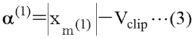
- shift scaling is performed as in the following equations (2) to (4).
- a kernel signal sequence ⁇ (1) u (1) p ( ) obtained by performing time shift ⁇ (n ⁇ m (1) ) mod N FFT ⁇ , amplitude scaling ⁇ (1), and phase scaling u (1).
- nm (1) ) mod N FFT ) is output.
- address m (1) data signal sequence with reduced amplitude peak at xn (1) is obtained.
- the frequency component Since the data signal sequence xn (1) obtained by this calculation is obtained by subtraction of the shifted and scaled kernel signal sequence from the original data signal sequence x_n, the frequency component has a characteristic that does not change except for the reserved tone.
- This iterative calculation is executed until the number of repetitions i reaches a predetermined number of repetitions, and after completion of the iterative calculation, a data signal sequence for one symbol in which PAPR is suppressed is output.
- the disadvantage of GBA is that the value of the reserved tone increases as the number of iterations increases.
- the value of the reserved tone after TR has an upper limit.
- the power of the reserved tone is a sub-band other than the reserved tone. The power is limited to 10 times or less than the carrier power. Therefore, when the algorithm is applied as it is, there are cases where the standard is not satisfied.
- FIG. 4A is a diagram showing a configuration of TR400 as a prerequisite technology.
- a kernel signal sequence for one symbol is stored in the kernel cache 401 and a data signal sequence for one symbol is stored in the symbol cache 402.
- the reserved tone cache (reserved tone cache in the figure) 405 stores the frequency components of the reserved tone of the data signal sequence, and all the initial states are set to “0”.
- the symbol cache 402 is overwritten with each updated data signal sequence each time GBA is repeated.
- the value of the reserved tone cache 405 is determined based on the shift amount and the scaling amount used for the iteration by the shift scaling unit 404 and the reserved tone update calculation unit (reserved tone update in the figure).
- the updated value of the reserved tone component calculated by the calculation unit 406 is subtracted and overwritten.
- the peak detection unit 403 calculates an address m (i) that takes the peak value of the input data signal sequence xn (i-1) and a data value xm (i) (i-1) at the address, The value is input to the scaling unit 404.
- the shift scaling unit 404 stores the value rk (i-1) of the reserved tone cache 405, the address m (i) of the data signal sequence that takes a peak, and the data value xm (i) (i-1) at that address. Based on, the amplitude scaling value ⁇ (i) and the phase scaling value u (i) are calculated and output. At the same time, the shift scaling unit 404 applies a signal sequence ⁇ (i) u (i) p ((nm (i) ) mod obtained by applying the scaling value and the time shift value to the kernel signal sequence pn output from the kernel cache 401. N FFT ) is calculated and output as a peak suppression signal sequence.
- the symbol subtraction unit 407 uses the signal sequence ⁇ (i) u (i) p ((nm ) output from the shift scaling unit 404 from the data signal sequence read from the symbol cache 402 according to the equation (5). (i) ) mod N FFT ) is subtracted to calculate and output the updated data signal sequence xn (i) .
- phase scaling value u (i) is calculated by the same calculation as Expression (7).
- the amplitude scaling value ⁇ (i) is devised to calculate a value such that the value of the reserved tone does not exceed the specified value after the iteration.
- the scaling value ⁇ (i) calculated by the following formulas (8) to (10 ) is used.
- the data signal sequence is updated from xn (i-1) to xn (i) and overwritten in the symbol cache 402, and at the same time, the data signal sequence xn (i ) Is entered.
- the reserved tone update calculation unit 406 obtains the amplitude scaling value ⁇ (i) , the phase scaling value u (i), and the peak address m (i) in the calculation process of the shift / scaling unit 404. Based on these, the reserved tone update value ⁇ (i) vk (i) (vk (i) is a value calculated by the calculation of Expression (8). The value is stored in the calculation of (8) and can be reused).
- the reserved tone subtraction unit 408 subtracts the value obtained by the reserved tone update calculation unit 406 from the value of the reserved tone cache 405 as shown in the equation (11), so that the reserved tone cache 405 The value is updated from rk (i-1) to rk (i) .
- the PAPR can be suppressed while the reserved tone value is kept below the specified value.
- FIG. 4B is a block diagram illustrating a configuration of the shift / scaling unit 404 of the base technology.
- the shift / scaling unit 404 calculates a subtraction value for peak suppression within a specified value to the symbol subtraction unit 407, and calculates a scaling value used by the calculation unit 441 and the reserved tone update calculation unit 406. And an arithmetic unit 442 that performs the operation.
- the calculation unit 441 includes a shift value ⁇ (nm (1) ) mod N FFT ⁇ based on the address (m (i) ) from the peak detection unit 403, a kernel signal sequence (pn) from the kernel cache 401, From the scaling values ( ⁇ (i) , u (i) ) from the calculation unit 442, a subtraction value for peak suppression within a specified value (see formula (5)) is calculated as a peak suppression signal string. Then, the calculation unit 441 outputs the subtraction value to the symbol subtraction unit 407.
- the arithmetic unit 442 includes a threshold V clip storage unit 442a that determines the amplitude of the data signal sequence xn.
- the calculation unit 442 is based on the frequency component (rk (i-1) ) of the reserved tone from the reserved tone cache 405 and the address (m (i) ) from the peak detection unit 403,
- the scaling values ( ⁇ (i) , u (i) ) are calculated according to 10). Then, the calculation unit 442 outputs the scaling values ( ⁇ (i) , u (i) ) to the calculation unit 441 and the reserved tone update calculation unit 406.
- the present embodiment solves such a problem and suppresses the frequency component of the reserved tone in the tone reservation to a specified value, and then maximizes the PAPR suppression amount of the data signal sequence, and the following peak suppression circuit and An OFDM modulator using a peak suppression circuit is proposed.
- FIG. 2A is a block diagram showing a configuration of the peak suppression circuit 200 according to the present embodiment.
- the peak suppression circuit 200 of the present embodiment includes a tone reservation execution unit (ToneTReservation execution unit in the drawing) 201 and a reserved tone suppression unit (reserved Tone suppression unit in the drawing) 202.
- the tone reservation execution unit 201 receives the time series data signal sequence (xn) and the time series kernel signal sequence (pn) having a value in the frequency component of the reserved tone, and executes tone reservation, thereby performing peak reservation.
- the suppressed data signal sequence (x′n) is output.
- the kernel signal sequence and the data signal sequence input to the tone reservation execution unit 201 are not directly used signals obtained by inverse Fourier transform in the preceding OFDM modulation, but input signals obtained by interpolating them. It is good. This is not limited to the present embodiment, and the same applies to the following embodiments.
- the tone reservation execution unit 201 includes a kernel cache 211, a symbol cache 212, a peak detection unit 213, a shift scaling unit 214, a reserved tone cache 215, a reserved tone update calculation unit 216, and a symbol subtraction unit. 217 and a reserved tone subtracting unit 218.
- the value of the kernel signal sequence is accumulated in the kernel cache 211, and the value of the data signal sequence is accumulated in the symbol cache 212.
- the reserved tone cache 215 stores reserved tone frequency components of the data signal sequence, and the initial state is all set to “0”.
- the peak detection unit 213 calculates an address m (i) that takes a peak value of the input data signal sequence xn (i-1 ) and a data value xm (i) (i-1) at the address, and shifts it. Output to the scaling unit 214.
- the shift / scaling unit 214 has an address m (i) of the data signal sequence, a data value xm (i) (i-1) at the address, an amplitude scaling value ⁇ (i), and a phase scaling value u (i). Are calculated and output. At the same time, the shift / scaling unit 214 applies a signal sequence ⁇ (i) u (i) p ((nm (i ) obtained by applying a time shift value and a scaling value to the kernel signal sequence pn read from the kernel cache 211. ) ) mod N FFT ) is output as a peak suppression signal sequence. It should be noted that the amplitude scaling value ⁇ (i) is calculated by the same calculation as Expression (6), and the phase scaling value u (i) is calculated by the same calculation as Expression (7).
- the shift / scaling unit 214 of the tone reservation execution unit 201 is not subjected to suppression by the value of the reserved tone stored in the reserved tone cache 215. Therefore, even if the value of the cache (N TR data strings) that retains the reserved tone during the iteration reaches the specified value, the subsequent iteration is continued, and as a result, sufficient PAPR suppression of the data signal string is achieved. A quantity is obtained.
- FIG. 2B is a block diagram showing a configuration of the shift / scaling unit 214 according to the present embodiment.
- the shift scaling unit 214 is used by a calculation unit 241 that generates a subtraction value for peak suppression without suppression corresponding to the reserved tone to the symbol subtraction unit 217, and a calculation unit 241 and a reserved tone update calculation unit 216.
- An arithmetic unit 242 that calculates a scaling value to be calculated.
- a shift value ⁇ (n ⁇ m (1) ) mod N FFT ⁇ based on the address (m (i) ) is input from the peak detection unit 213 to the arithmetic unit 241, and a kernel signal sequence (pn) is received from the kernel cache 211. Then, a scaling value ( ⁇ (i) , u (i) ) is input from the calculation unit 242. Based on these, the calculation unit 241 calculates a subtraction value for peak suppression (see Equation (5)) as a peak suppression signal string without suppression according to the reserved tone. Then, the calculation unit 241 outputs the subtraction value to the symbol subtraction unit 217.
- the calculation unit 242 includes a threshold value V clip storage unit 242a for determining the amplitude of the data signal sequence xn.
- the threshold value V clip may be input from the outside.
- the calculation unit 242 Based on the address (m (i) ) from the peak detection unit 213, the calculation unit 242 calculates scaling values ( ⁇ (i) , u (i) ) according to equations (6) and (7). Then, the calculation unit 242 outputs the scaling values ( ⁇ (i) , u (i) ) to the calculation unit 241 and the reserved tone update calculation unit 216.
- the time shift can be realized by adjusting an address at which data reading from the kernel cache 211 is started.
- the peak address m (i) output from the peak detector 213 is input to the kernel cache 211, and the read start position is adjusted based on the peak address m (i) .
- the read start position is adjusted based on the peak address m (i) .
- the symbol subtraction unit 217 performs a kernel signal sequence ⁇ (i) u (i) that is time-shifted and scaled by the shift / scaling unit 214 from the data signal sequence xn (i ⁇ 1) read from the symbol cache 212.
- p ((nm (i) ) mod N FFT ) (see equation (5))
- the data signal sequence is updated (xn (i-1) ⁇ xn (i) ).
- the reserved tone update calculation unit 216 receives the amplitude scaling value ⁇ (i) , the phase scaling value u (i), and the peak address m (i) output from the shift scaling unit 214 as inputs, ), The reserved tone update value sequence ⁇ (i) vk (i) is output.
- the reserved tone subtraction unit 218 uses the reserved tone value sequence rk (i ⁇ 1) read from the reserved tone cache 215 and the reserved tone update value sequence ⁇ output from the reserved tone update calculation unit 216. (i) The reserved tone value string is updated from rk (i -1) to rk (i) by subtracting vk (i) (see equation (8)).
- the updated data signal sequence xn (i) is output as an output signal of the tone reservation execution unit 201 when the number of iterations i is the limit number of iterations, and is overwritten in the symbol cache 212 otherwise.
- the next iterative calculation is started after being input to the detection unit 213.
- the reserved tone suppression unit 202 includes a tone processing unit (tone processing unit in the figure) 221, an IDFT unit (inverse Fourier transform unit) 222, and a subtraction unit 223.
- the tone processing unit 221 receives the frequency component of the reserved tone of the data signal sequence after peak suppression as input, and creates a frequency data sequence that suppresses components that exceed the specified value.
- the IDFT unit 222 converts the frequency data sequence, which is the output of the tone processing unit, into time series data by performing inverse Fourier transform.
- the subtracting unit 223 subtracts the output signal of the IDFT unit 222 from the data signal sequence after peak suppression and outputs the result.
- FIG. 2C is a block diagram illustrating a configuration of the tone processing unit 221 according to the present embodiment.
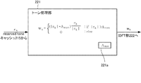
- the tone processing unit 221 obtains the frequency component of the reserved tone frequency component rk (k is an address corresponding to the reserved tone frequency) from the peak-suppressed data signal sequence, and sets the reserved tone frequency value wk below. It is calculated by the following formula (12).
- the value wk is converted into time-series data cn by Equation (13) by the IDFT unit 222, and then subtracted from the data signal sequence xn after peak suppression by Equation (14) by the subtractor 223.
- a peak-suppressed data signal sequence yn in which the reserved tone value falls within the specified value is obtained.
- the processing method of the tone processing unit 221 is not limited to Equation (12), and reserved tone suppression is performed by appropriately selecting a scaling value as in Equations (15) and (16) below. A method is also conceivable.
- the processing method of the tone processing unit proposed here is not limited to this embodiment, and the same applies to the following embodiments.
- an operation that speeds up the operation such as inverse Fourier fast transform (IFFT) may be used.
- IFFT inverse Fourier fast transform
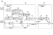
- FIG. 2D is a block diagram showing a configuration of an OFDM modulator 250 that uses the peak suppression circuit 200 according to the present embodiment.
- 2D is an example of the OFDM modulator 250 and is not limited to this configuration.
- the peak suppression circuit 200 according to the present embodiment can also be applied to an OFDM demodulator.
- the OFDM modulator 250 includes a data signal sequence mapping unit 251, a serial-parallel conversion unit 252, a subcarrier mapping unit 253, an IFFT unit 254, the peak suppression circuit 200 of the present embodiment, a guard interval insertion unit 256, A parallel conversion unit 257.
- the data signal sequence mapping unit 251 maps the input bit sequence to symbols represented by vectors according to the modulation scheme.
- the serial-parallel conversion unit 252 converts serial symbols into parallel, and the subcarrier mapping unit 253 transmits symbols in parallel by a plurality of subcarriers whose phases and amplitudes are set according to the types of parallel symbols.
- the IFFT unit 254 combines the parallel symbols to generate an OFDM signal. However, depending on the combination of symbols in IFFT section 254, a very large peak occurs.
- the peak suppression circuit 200 of the present embodiment reliably suppresses such a peak by tone reservation and realizes suppression of the reserved tone to a specified value or less.
- the guard interval insertion unit 256 inserts a guard interval code so that a plurality of multiplexed transmission data does not interfere with data of previous and subsequent times.
- the parallel-to-serial conversion unit 257 converts the parallel multiplex transmission data into a serial and generates an output bit string.
- the peak suppression circuit of this embodiment can also be realized by peak suppression processing by a processor according to the following procedure.
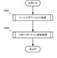
- FIG. 5A is a flowchart showing a processing procedure of the peak suppression circuit 200 according to the present embodiment.
- step S501 the peak suppression circuit 200 executes a tone reservation process without suppression according to the updated reserved tone.
- step S503 the peak suppression circuit 200 executes the reserved tone suppression process using the frequency component of the reserved tone corresponding to the tone reservation result.
- FIG. 5B is a flowchart showing a procedure of tone reservation processing (S501) according to the present embodiment.
- the peak suppression circuit 200 acquires and holds the data signal sequence xn and the kernel signal sequence pn in step S511. In step S513, the peak suppression circuit 200 detects the peak of the data signal sequence.
- the target for detecting the peak is the data signal sequence acquired in step S511 in the first iteration, and the updated data signal sequence during the iteration from step S523.
- step S515 the peak suppression circuit 200 calculates a time shift value, an amplitude scaling value, and a phase scaling value based on the peak detection result (address, data value at the address) and the threshold value V clip of the amplitude value.
- step S517 the peak suppression circuit 200 performs time shift, amplitude scaling, and phase scaling on the kernel signal sequence pn to generate a peak suppression signal sequence.
- step S519 the peak suppression circuit 200 subtracts the shifted and scaled kernel signal sequence from the data signal sequence xn (i-1) to update the data signal sequence xn (i) with the suppressed amplitude peak.
- step S521 the peak suppression circuit 200 updates the reserved tone value based on the address, the amplitude scaling value, and the phase scaling value, and stores them in the cache.
- step S523 the peak suppression circuit 200 determines whether the number of iterations has reached the limit number. If the number of iterations has not reached the limit number, the peak suppression circuit 200 returns to step S513 and repeats the update of the data signal sequence xn (i) in which the amplitude peak is suppressed. If the number of iterations reaches the limit number, the peak suppression circuit 200 outputs the data signal sequence x′n with the peak suppressed in step S525 and returns.
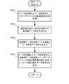
- FIG. 5C is a flowchart showing a procedure of reserved tone suppression processing (S503) according to the present embodiment.
- step S531 the peak suppression circuit 200 acquires the data signal sequence x′n whose peak is suppressed and the frequency component rk of the reserved tone corresponding to the data signal sequence x′n.
- step S533 the peak suppression circuit 200 generates a frequency data string wk that suppresses components that exceed the specified value Amax .
- step S535 the peak suppression circuit 200 performs inverse Fourier transform on the frequency data string wk to generate time series data cn.
- step S537 the peak suppression circuit 200 subtracts the time-series data cn from the peak-suppressed data signal sequence x′n, and the reserved tone value falls within the specified value A max.
- the data signal sequence yn is output.
- the peak suppression circuit according to the present embodiment is different from the second embodiment in that the tone reservation unit includes a plurality of peak detection units and a plurality of shift / scaling units. Since other configurations and operations are the same as those of the second embodiment, the same configurations and operations are denoted by the same reference numerals, and detailed description thereof is omitted.
- FIG. 6 is a block diagram showing the configuration of the peak suppression circuit 600 according to this embodiment.
- the same components as those in FIG. 2A are denoted by the same reference numerals, and description thereof is omitted.
- the peak suppression circuit 600 of this embodiment includes a tone reservation execution unit 601 and a reserved tone suppression unit 202.
- the tone reservation execution unit 601 includes a kernel cache 211, a symbol cache 212, a multiple peak detection unit 613, first to qth shift scaling units 6141 to 614q, and a reserved tone cache 215.
- the tone reservation execution unit 601 includes a reserved tone update calculation unit 616, a symbol subtraction unit 617, and a reserved tone subtraction unit 618.
- the reserved tone suppression unit 202 includes a tone processing unit 221, an IDFT unit 222, and a subtraction unit 223.
- tone reservation execution unit 601 The operation of the i-th iteration of the tone reservation execution unit 601 will be described below. In addition, regarding the definitions of symbols described below, the definitions described in the background art are followed.
- the multiple peak detector 613 has an address ms (i) (1 ⁇ s ⁇ q) that takes q amplitude peak values from the input data signal sequence xn (i ⁇ 1) , and a data value xms at that address. (i) (i-1) is calculated, and the address and the data value at the address are output as a pair to the s-th shift / scaling unit 614s (1 ⁇ s ⁇ q).
- q is a number specified in advance.
- the sth shift / scaling unit 614 s (1 ⁇ s ⁇ q) receives the address ms (i) of the data signal sequence and the data value xms (i) (i ⁇ 1) at the address, and receives the amplitude scaling value ⁇ s. Calculate (i) and phase scaling value us (i) and output.
- the s-th shift / scaling unit 614s (1 ⁇ s ⁇ q) outputs a signal sequence ⁇ s (i) us obtained by applying a time shift value and a scaling value to the kernel signal sequence pn read from the kernel cache 211.
- (i) p ((n ⁇ ms (i) ) mod N FFT ) is output as a peak suppression signal sequence.
- the amplitude scaling value ⁇ s (i) is obtained by the calculation of the following formula (17), and the phase scaling value us (i) is obtained by the calculation of the formula (18).
- N FFT data signal sequences xn (i-1) are divided into q, and an address having the maximum peak value in each region and its address are divided.
- x (j + 1) There is a method of listing addresses taking (i-1)
- the multiple peak detection method is not limited to these two types.
- the symbol subtraction unit 617 outputs a kernel signal sequence ⁇ s that is time-shifted and scaled, which is an output of the s-th shift / scaling unit 614 s, from the data signal sequence xn (i ⁇ 1) read from the symbol cache 212.
- ⁇ s that is time-shifted and scaled
- p ((n ⁇ ms (i) ) mod N FFT ) is subtracted as shown in the following equation (19) to update the data signal sequence (xn (i ⁇ 1) ⁇ xn (i) ).
- the reserved tone update calculation unit 616 receives the amplitude scaling value ⁇ s (i) , the phase scaling value us (i), and the peak address ms (i) output from the shift / scaling unit 614s, and inputs the following equation (20). ) To output the updated value sequence ⁇ s (i) v (k, s) (i) of the reserved tone.
- the reserved tone subtracting unit 618 uses the reserved tone value sequence rk (i ⁇ 1) output from the reserved tone cache 215, and ⁇ s (i) v that is the output of the reserved tone update calculating unit 616. By subtracting q of (k, s) (i) , the reserved tone value string is updated from rk (i -1) to rk (i) as shown in the following equation (21).
- the updated data signal sequence xn (i) is output as an output signal of the tone reservation execution unit 601 when the number of iterations i is the limit number of iterations. Input to the peak detector 613 and the next iterative operation is started.
- the time shift can be realized by adjusting an address at which data reading from the kernel cache 211 is started.
- the peak address ms (i) output from the multiple peak detector 613 to the s-th shift / scaling unit 614 s is input to the kernel cache 211, and the read start position is adjusted based on the peak address ms (i) .
- the read start position is adjusted based on the peak address ms (i) .
- ⁇ N FFT ⁇ ms (i) where the normal reading start position is set to address “0”
- sequential reading is performed, and when the address reaches ⁇ N FFT ⁇ 1 ⁇ , “0” is set.
- a time shift p ((n-ms (i) ) mod N FFT ) is realized.
- Such a configuration is also included in the present embodiment.
- the peak suppression circuit according to the present embodiment performs Fourier transform on the frequency component of the reserved tone used by the reserved tone suppression unit and the data signal sequence after peak suppression. It differs in that it is generated by doing.
- Other configurations and operations are the same as those in the second embodiment and the third embodiment. Therefore, the same configurations and operations are denoted by the same reference numerals, and detailed description thereof is omitted.
- FIG. 7 is a block diagram showing the configuration of the peak suppression circuit 700 according to this embodiment.
- the same components as those in FIG. 2A are denoted by the same reference numerals, and the description thereof is omitted.
- the frequency component of the reserved tone that is input to the tone processing unit 221 of the reserved tone suppression unit 202 is generated by performing a Fourier transform on the data signal sequence x′n after peak suppression by the DFT unit 703.
- the This configuration is a configuration in the case where the reserved tone frequency component of the data signal sequence after peak suppression is not calculated by the tone reservation execution unit 201.
- the DFT unit 703 may use an operation that speeds up the operation, such as fast Fourier transform (FFT).
- FFT fast Fourier transform
- the tone reservation execution unit 201 may be replaced with a tone reservation execution unit 601.
- the configuration in which the frequency component of the reserved tone generated by the tone reservation execution unit and the result obtained by performing the Fourier transform in the DFT unit 703 on the peak-suppressed data signal sequence are also used in this embodiment. included.
- the tone reservation execution unit does not calculate the frequency component of the reserved tone
- the PAPR suppression amount of the data signal sequence is maximized while the frequency component of the reserved tone is suppressed to the specified value. can do. Therefore, by applying the present invention to a radio transmitter, a transmitter with high power efficiency can be provided.
- the peak suppression circuit according to the present embodiment differs from the second to fourth embodiments in the configuration of the tone reservation execution unit. Since other configurations and operations are the same as those in the second to fourth embodiments, the same configurations and operations are denoted by the same reference numerals, and detailed description thereof is omitted.
- FIG. 8A is a block diagram showing the configuration of the peak suppression circuit 800 according to the present embodiment.
- the same components as those in FIG. 2A are denoted by the same reference numerals, and description thereof is omitted.
- the peak suppression circuit 800 of the present embodiment includes a tone reservation execution unit (ToneTReservation execution unit in the figure) 801 and a reserved tone suppression unit (reserved Tone suppression unit in the drawing) 202.
- the tone reservation execution unit 801 of this embodiment includes a multiple kernel cache 811, a symbol cache 212, a peak detection unit 213, a scaling unit 814, a reserved tone cache 215, a reserved tone update calculation unit 216, A symbol subtracting unit 217 and a reserved tone subtracting unit 218 are provided.
- the values of the plurality of kernel signal sequences are accumulated in the plurality of kernel caches 811 and the values of the data signal sequences are accumulated in the symbol cache 212.
- the plurality of kernel signal sequences include, for example, a signal sequence obtained by performing an inverse Fourier transform on a frequency component having a value of “1” at an address where a reserved tone value is present and otherwise having a value of “0”. This is configured and expressed as an equation (22).
- the reserved tone cache 215 stores reserved tone frequency components of the data signal sequence, and the initial state is all set to “0”.
- the peak detection unit 213 calculates an address m (i) that takes a peak value of the input data signal sequence xn (i-1 ) and a value xm (i) (i-1) at the address, and a scaling unit Output to 814.
- the scaling unit 814 calculates the amplitude scaling value ⁇ (i) and the phase scaling value u (i) from the address m (i) of the data signal sequence and the value xm (i) (i ⁇ 1) at the address. And output. At the same time, the scaling unit 814 suppresses the peak of the signal sequence ⁇ (i) u (i) pn k (i) obtained by applying the scaling value to the kernel signal sequence pn k (i) read from the plurality of kernel caches 811. Output as a signal sequence. It should be noted that the amplitude scaling value ⁇ (i) is calculated by the same calculation as Expression (6), and the phase scaling value u (i) is calculated by the same calculation as Expression (7).
- the column number k (i) of the kernel signal sequence pn k (i) read from the multiple kernel caches 811 is the address m (i) of the data signal sequence and the value xm (i) (i-1) at that address. Is determined. For example, the column number that takes the maximum value is selected by comparing the amplitude values at the address m (i) of each kernel signal sequence. In addition, in order to omit the phase scaling calculation in the scaling unit 814, which will be described later, the column number closest to the phase value of xm (i) (i-1) at the address m (i) is selected. There are also methods. Further, a method combining the above two types of determination methods, a method of selecting a column number in order for each iteration without using m (i) and xm (i) (i-1), and the like are also included.
- the scaling unit 814 of the tone reservation execution unit 801 is not subjected to suppression by the value of the reserved tone stored in the reserved tone cache 215. Therefore, even if the value of the cache (N TR data strings) that retains the reserved tone during the iteration reaches the specified value, the subsequent iteration is continued, and as a result, sufficient PAPR suppression of the data signal string is achieved. A quantity is obtained.
- FIG. 8B is a block diagram illustrating a configuration of the scaling unit 814 according to the present embodiment.
- the same components as those in FIG. 2B are denoted by the same reference numerals, and description thereof is omitted.
- the scaling unit 814 generates a subtraction value for peak suppression without suppression according to the reserved tone to the symbol subtraction unit 217, and scaling used by the calculation unit 841 and the reserved tone update calculation unit 216. And a calculation unit 242 for calculating a value.
- the calculation unit 841 corresponds to the reserved tone from the kernel signal sequence (pn k (i) ) from the plurality of kernel caches 811 and the scaling values ( ⁇ (i) , u (i) ) from the calculation unit 242.
- the symbol subtraction unit 217 obtains the kernel signal sequence ⁇ (i) u (i) pn k (i) scaled by the scaling unit 814 from the data signal sequence x n (i ⁇ 1) read from the symbol cache 212. By subtracting (see Equation (5)), the data signal sequence is updated (xn (i-1)- > xn (i) ).
- the updated data signal sequence xn (i) is output as an output signal of the tone reservation execution unit 801 when the number of iterations i is the limit number of iterations.
- the next iterative calculation is started after being input to the detection unit 213.
- the reserved tone suppression unit 202 includes a tone processing unit (tone processing unit in the figure) 221, an IDFT unit (inverse Fourier transform unit) 222, and a subtraction unit 223.
- tone processing unit tone processing unit in the figure
- IDFT unit inverse Fourier transform unit
- subtraction unit 223 The frequency component of the reserved tone of the data signal sequence after suppression is input, and the component exceeding the specified value in the data signal sequence after peak suppression is suppressed.
- the reserved tone frequency component of the data signal sequence after peak suppression is input to the reserved tone suppression unit 202.
- the reserved tone suppression unit 202 As shown in FIG. May be generated by Fourier transforming the data signal sequence after peak suppression.
- the PAPR suppression amount of the data signal sequence can be maximized while the frequency component of the reserved tone is suppressed to the specified value. Therefore, by applying the present invention to a radio transmitter, a transmitter with high power efficiency can be provided.
- the present invention may be applied to a system composed of a plurality of devices, or may be applied to a single device. Furthermore, the present invention can also be applied to a case where an information processing program that implements the functions of the embodiments is supplied directly or remotely to a system or apparatus. Therefore, in order to realize the functions of the present invention on a computer, a program installed on the computer, a medium storing the program, and a WWW (World Wide Web) server that downloads the program are also included in the scope of the present invention. . In particular, at least a non-transitory computer readable medium storing a program for causing a computer to execute the processing steps included in the above-described embodiments is included in the scope of the present invention.
- a kernel signal sequence generated using a reserved tone prepared in advance and a data signal sequence of an orthogonal frequency division multiplexing system are input to the data signal sequence without suppression according to the reserved tone to be updated.
- Tone reservation execution means for executing tone reservation on the output and outputting a data signal sequence after peak suppression; By inputting the data signal sequence after the peak suppression and the frequency component of the reserved tone corresponding to the data signal sequence after the peak suppression, the component exceeding the specified value generated from the frequency component is suppressed.
- a peak suppression circuit comprising: (Appendix 2)
- the reserved tone suppression means is A tone processing unit that inputs the frequency component and outputs the frequency data string; An inverse Fourier transform unit that outputs the frequency data string by performing an inverse Fourier transform; Subtracting the output of the inverse Fourier transform unit from the data signal sequence after peak suppression, and outputting a data signal sequence in which the reserved tone is within the specified value; and
- the peak suppression circuit according to Supplementary Note 1, wherein (Appendix 3) When the frequency component exceeds the specified value, the tone processing unit sets the difference between the value of the frequency component and the specified value as an amplitude value, the phase as the same value as the frequency component, and the frequency component
- the peak suppression circuit according to appendix 2 wherein when the prescribed value is not exceeded, the frequency data string is output with the frequency component value set
- the tone reservation execution means includes: A kernel cache for accumulating the value of the kernel signal sequence and reading the value; A symbol cache for accumulating values of the data signal sequence of the orthogonal frequency division multiplexing system and reading the values; A tone cache for accumulating a reserved tone value sequence corresponding to the orthogonal frequency division multiplexing data signal sequence and reading the value sequence; A peak detection unit that outputs an address at which the amplitude value of the data signal sequence of the orthogonal frequency division multiplexing system peaks and a data value at the address; Based on the output of the peak detector, a time shift value and a scaling value are calculated and output, and the time shift value and the scaling value are applied to the kernel signal sequence read from the kernel cache.
- the tone reservation execution means includes: A kernel cache for accumulating the value of the kernel signal sequence and reading the value; A symbol cache for accumulating values of the data signal sequence of the orthogonal frequency division multiplexing system and reading the values; A tone cache for accumulating reserved tone values corresponding to the orthogonal frequency division multiplexing data signal sequence and reading the values; A plurality of peak detectors for outputting a plurality of sets of addresses at which the amplitude
- a plurality of shift / scaling units that output the peak suppression signal sequence;
- a tone update calculation unit that calculates and outputs an update value sequence of the reserved tone value sequence based on the time shift value and the scaling value output from the plurality of shift scaling units;
- a symbol subtraction unit that updates the data signal sequence by subtracting the peak suppression signal sequence from the data signal sequence read from the symbol cache;
- a tone subtraction unit that updates the value of the reserved tone by subtracting the output of the tone update operation unit from the value of the reserved tone read from the tone cache;
- the peak suppression circuit according to any one of appendices 1 to 4, which includes: (Appendix 8)
- the plurality of peak detectors outputs a set of addresses having the peak amplitude value of the data signal sequence of the orthogonal frequency division multiplexing method and the data value at the address in a specified number in descending order of the amplitude value.
- the tone reservation execution means includes: A plurality of kernel caches for accumulating a plurality of values of the kernel signal sequence and reading the values; A symbol cache for accumulating values of the data signal sequence of the orthogonal frequency division multiplexing system and reading the values; A tone cache for accumulating reserved tone values corresponding to the orthogonal frequency division multiplexing data signal sequence and reading the values; A peak detection unit that outputs a set of an address at which the amplitude value of the data signal sequence of the orthogonal frequency division multiplexing system peaks and a data value at the address; A scaling unit that calculates and outputs a scaling value based on the output of the peak detection unit, and outputs a peak suppression signal sequence in which the scaling value is applied to a kernel signal sequence read from
- An orthogonal frequency division multiplexing modulator comprising the peak suppression circuit according to any one of appendices 1 to 10.
- a kernel signal sequence generated using a reserved tone prepared in advance and a data signal sequence of an orthogonal frequency division multiplexing method are input to the data signal sequence without suppression according to the reserved tone to be updated.
- a tone reservation execution step for executing tone reservation and outputting a data signal sequence after peak suppression; A frequency that suppresses a component that exceeds a specified value, generated from the frequency component, with the data signal sequence after the peak suppression and the frequency component of the reserved tone corresponding to the data signal sequence after the peak suppression as inputs.
- the peak suppression method containing. (Appendix 13) A kernel signal sequence generated using a reserved tone prepared in advance and a data signal sequence of an orthogonal frequency division multiplexing method are input to the data signal sequence without suppression according to the reserved tone to be updated.
Landscapes
- Engineering & Computer Science (AREA)
- Computer Networks & Wireless Communication (AREA)
- Signal Processing (AREA)
- Digital Transmission Methods That Use Modulated Carrier Waves (AREA)
Abstract
トーンリザベーション処理において、リザーブド・トーンの周波数成分を規定値に抑えた上で、データ信号列のPAPR抑制量を最大化するため、あらかじめ用意されたリザーブド・トーンを用いて生成されたカーネル信号列と、直交周波数分割多重方式のデータ信号列とを入力して、更新されるリザーブド・トーンに応じた抑制なしにデータ信号列に対してトーンリザベーションを実行して、ピーク抑制後のデータ信号列を出力するトーンリザベーション実行部と、ピーク抑制後のデータ信号列と、ピーク抑制後のデータ信号列に対応する前記リザーブド・トーンの周波数成分とを入力して、周波数成分から生成した、規定値を超えた成分を抑制する周波数データ列に対し逆フーリエ変換を施した値を、ピーク抑制後のデータ信号列から減算して、リザーブド・トーンが前記規定値以内に収まったデータ信号列を出力するリザーブド・トーン抑制部と、を備える。
Description
本発明は、ピーク抑制回路、ピーク抑制方法および直交周波数分割多重方式変調器に関する。
携帯電話や無線LAN(Local Area Network)や地上デジタル放送など、近年の無線通信に用いられているデジタル変調方式は、QPSK(Quadrature Phase Shift Keying)や多値QAM(Quadrature Amplitude Modulation)などの変調フォーマットが採用されている。このような変調フォーマットでは、一般に、シンボル間の遷移時に信号の軌跡が振幅変調を伴い、マイクロ波帯のキャリア信号に重畳された高周波変調信号では、時間とともに信号の振幅(包絡線)が変化する。
高周波変調信号のピーク電力と平均電力の比であるPAPR(Peak-to-Average Power Ratio)が大きい信号を増幅する場合は、高い線形性を確保するために、ピーク電力に対しても波形が歪まないように電源から十分に大きな電力を増幅器に供給する必要がある。言い換えると、増幅器を電源電圧で制限される飽和電力よりも十分低い電力領域で余裕(バックオフ)をもたせて動作させる必要がある。一般に、A級やB級動作させた線形増幅器では、その飽和出力電力付近で電力効率が最大になるので、バックオフが大きい領域で動作させると平均的な効率は低くなる。
直交周波数分割多重方式(OFDM:Orthogonal Frequency-Division Multiplexing)の無線信号のPAPRを抑制する方法としては、CFR(Crest Factor Reduction)が知られており、非特許文献1における記載など、様々なアルゴリズムが提案されている。CFRにはSLM(Selected Mapping)やACE(Active Constellation Extension)やTR(Tone Reservation)など様々な方式が存在している。海外の地上デジタル放送規格であるDVB-T2においては、TRが標準化に組み込まれており、さらにETSI(European Telecommunication Standards Institute)のガイドラインにおいて、非特許文献2にアルゴリズムの実装方式が記されている。ETSIに記載のアルゴリズムは、非特許文献3に記載のGBA(Gradian Based Algorithm)をベースとしている。
しかし、GBAの欠点としては、反復回数の増加に伴い、リザーブド・トーン(reserved tone:予約されたトーン)の値が増加することが挙げられる。TR後のリザーブド・トーンの値には上限がある。例えば、地上デジタル放送の変調規格DVB-T2(Digital Video Broadcasting-Terrestrial 2)においては、非特許文献4に記載される通り、リザーブド・トーンのパワーがリザーブド・トーン以外のサブキャリアのパワーと比べて10倍以内に抑えるように制限されている。よって、ETSIに記載のアルゴリズムをそのまま適用した場合、規格を満たさなくなるケースがある。この問題に対して、ETSI記載のガイドラインでは、GBAを改良したアルゴリズムが提案されている。このアルゴリズムは、基本的にはGBAをベースとしており、データ信号列の更新が行われている。ただし、振幅スケーリング値の決定方法が異なっており、データ信号列の値を更新する度に、対応するリザーブド・トーンの値を更新した上で、その値はカーネル信号列の振幅スケーリング値の決定に反映される。このアルゴリズムの手順によって反復演算を実行することにより、リザーブド・トーンの値を規定値以下に抑えたまま、PAPRの抑制が実現される。
Fa-Long Luo, Digital Front-End in Wireless Communication and Broadcasting, Cambridge University Press, 2011.
ETSI; "Digital Video Broadcasting (DVB); Frame structure channel coding and modulation for a second generation digital terrestrial television broadcasting system (DVB-T2)," ETSI EN 302 755 v1.2.0c, 2012.
Tellado-Mourelo, J.; "Peak to Average Power Reduction for Multicarrier Modulation," PhD thesis, Stanford University, Sept. 1999.
ETSI; "Digital Video Broadcasting (DVB); Frame structure channel coding and modulation for a second generation digital terrestrial television broadcasting system (DVB-T2)," ETSI TS 102 831 v1.2.1, 2012.
しかしながら、上述のETSI提案の方式では、反復途中でリザーブド・トーンを保持するキャッシュ(NTR個のデータ列)の値が1つでも規定値に達してしまった場合、それ以降の反復において、振幅スケーリング値がゼロ(“0”)となってしまう。これにより、以降の反復は実質的には行われなくなってしまい、十分な反復が実行できず、その結果、データ信号列の十分なPAPR抑制量が得られないという欠点があった。
本発明は、上述の課題を解決する技術を提供することを主な目的とする。
上記目的を達成するため、本発明の1態様に係るピーク抑制回路は、
あらかじめ用意されたリザーブド・トーンを用いて生成されたカーネル信号列と、直交周波数分割多重方式のデータ信号列とを入力して、更新されるリザーブド・トーンに応じた抑制なしに前記データ信号列に対してトーンリザベーションを実行して、ピーク抑制後のデータ信号列を出力するトーンリザベーション実行手段と、
前記ピーク抑制後のデータ信号列と、前記ピーク抑制後のデータ信号列に対応する前記リザーブド・トーンの周波数成分とを入力して、前記周波数成分から生成した、規定値を超えた成分を抑制する周波数データ列に対し逆フーリエ変換を施した値を、前記ピーク抑制後のデータ信号列から減算して、前記リザーブド・トーンが前記規定値以内に収まったデータ信号列を出力するリザーブド・トーン抑制手段と、
を備える。
あらかじめ用意されたリザーブド・トーンを用いて生成されたカーネル信号列と、直交周波数分割多重方式のデータ信号列とを入力して、更新されるリザーブド・トーンに応じた抑制なしに前記データ信号列に対してトーンリザベーションを実行して、ピーク抑制後のデータ信号列を出力するトーンリザベーション実行手段と、
前記ピーク抑制後のデータ信号列と、前記ピーク抑制後のデータ信号列に対応する前記リザーブド・トーンの周波数成分とを入力して、前記周波数成分から生成した、規定値を超えた成分を抑制する周波数データ列に対し逆フーリエ変換を施した値を、前記ピーク抑制後のデータ信号列から減算して、前記リザーブド・トーンが前記規定値以内に収まったデータ信号列を出力するリザーブド・トーン抑制手段と、
を備える。
上記目的を達成するため、本発明の他の態様に係る直交周波数分割多重方式変調器は、上記ピーク抑制回路を備える。
上記目的を達成するため、本発明の更に他の態様に係るピーク抑制方法は、
あらかじめ用意されたリザーブド・トーンを用いて生成されたカーネル信号列と、直交周波数分割多重方式のデータ信号列とを入力として、更新されるリザーブド・トーンに応じた抑制なしに前記データ信号列に対してトーンリザベーションを実行して、ピーク抑制後のデータ信号列を出力し、
前記ピーク抑制後のデータ信号列と、前記ピーク抑制後のデータ信号列に対応する前記リザーブド・トーンの周波数成分とを入力として、前記周波数成分から生成した、規定値を超えた成分を抑制する周波数データ列に対し逆フーリエ変換を施した値を、前記ピーク抑制後のデータ信号列から減算して、前記リザーブド・トーンが前記規定値以内に収まったデータ信号列を出力する。
あらかじめ用意されたリザーブド・トーンを用いて生成されたカーネル信号列と、直交周波数分割多重方式のデータ信号列とを入力として、更新されるリザーブド・トーンに応じた抑制なしに前記データ信号列に対してトーンリザベーションを実行して、ピーク抑制後のデータ信号列を出力し、
前記ピーク抑制後のデータ信号列と、前記ピーク抑制後のデータ信号列に対応する前記リザーブド・トーンの周波数成分とを入力として、前記周波数成分から生成した、規定値を超えた成分を抑制する周波数データ列に対し逆フーリエ変換を施した値を、前記ピーク抑制後のデータ信号列から減算して、前記リザーブド・トーンが前記規定値以内に収まったデータ信号列を出力する。
本発明の上記態様によれば、トーンリザベーション処理において、リザーブド・トーンの周波数成分を規定値に抑えた上で、データ信号列のPAPR抑制量を最大化することができる。そのため、本発明を無線送信機に適用することにより、電力効率が高い送信機を提供することができる。
以下に、図面を参照して、本発明の実施の形態について例示的に詳しく説明する。ただし、以下の実施の形態に記載されている構成要素は単なる例示であり、本発明の技術範囲をそれらのみに限定する趣旨のものではない。なお、明細書中の記号と数式中の記号との下付きや上付きに相違がある箇所は、基本的に数式中の記号に合わせるものとする。なお、図面中の矢印の向きは、一例を示すものであり、ブロック間の信号の向きを限定するものではない。
[第1実施形態]
本発明の第1実施形態としてのピーク抑制回路100について、図1を用いて説明する。ピーク抑制回路100は、OFDMにおいてピークを抑制する回路である。
本発明の第1実施形態としてのピーク抑制回路100について、図1を用いて説明する。ピーク抑制回路100は、OFDMにおいてピークを抑制する回路である。
図1に示すように、ピーク抑制回路100は、トーンリザベーション実行部101と、リザーブド・トーン抑制部102と、を含む。トーンリザベーション実行部101は、あらかじめ用意されたリザーブド・トーンを用いて生成されたカーネル信号列pnと、直交周波数分割多重方式のデータ信号列xnとを入力して、更新されるリザーブド・トーンに応じた抑制なしにデータ信号列xnに対してトーンリザベーションを実行して、ピーク抑制後のデータ信号列x'nを出力する。リザーブド・トーン抑制部102には、ピーク抑制後のデータ信号列x'nと、ピーク抑制後のデータ信号列x'nに対応するリザーブド・トーンの周波数成分rkとが入力される。リザーブド・トーン抑制部102は、周波数成分rkから生成した、規定値102aを超えた成分を抑制する周波数データ列に対し逆フーリエ変換を施した値を、ピーク抑制後のデータ信号列x'nから減算する。このようにしてリザーブド・トーン抑制部102は、リザーブド・トーンが規定値102a以内に収まったデータ信号列ynを出力する。
本実施形態によれば、更新されるリザーブド・トーンに対する抑制なしにトーンリザベーションを実行して、リザーブド・トーンの周波数成分を用いてリザーブド・トーンが規定値以内に収まるように処理する。したがって、トーンリザベーションにおいてリザーブド・トーンの周波数成分を規定値に抑えた上で、データ信号列のPAPR抑制量を最大化することができる。そのため、本発明を無線送信機に適用することにより、電力効率が高い送信機を提供することができる。
[第2実施形態]
次に、本発明の第2実施形態に係るピーク抑制回路について説明する。本実施形態に係るピーク抑制回路は、ETSI提案の方式であるGBAを改良したアルゴリズムに修正を加え、トーンリザベーションにおけるリザーブド・トーンの周波数成分を用いて、リザーブド・トーンが規定値以内に収まるような処理を追加する。
次に、本発明の第2実施形態に係るピーク抑制回路について説明する。本実施形態に係るピーク抑制回路は、ETSI提案の方式であるGBAを改良したアルゴリズムに修正を加え、トーンリザベーションにおけるリザーブド・トーンの周波数成分を用いて、リザーブド・トーンが規定値以内に収まるような処理を追加する。
《前提技術》
まず、本実施形態について説明する前に、その前提技術となるGBAの動作、および、ETSI記載のTRアルゴリズムの概要を説明する。ETSI記載のアルゴリズムは、非特許文献3のGBAをベースとしており、GBAの動作を説明する。
まず、本実施形態について説明する前に、その前提技術となるGBAの動作、および、ETSI記載のTRアルゴリズムの概要を説明する。ETSI記載のアルゴリズムは、非特許文献3のGBAをベースとしており、GBAの動作を説明する。
(GBAの概要)
図3は、前提技術のGBA300の構成を示す図である。GBAは、FFT(Fast Fourier Transform)/IFFT(Inverse FFT)1シンボルごとにピーク抑制が行われる。複素数の値を持つ1シンボル分のデータ信号列xn(0≦n≦NFFT-1、NFFTは1シンボルのデータ数)は、デジタルのデータ列を変調フォーマットに沿って変換して得られたサブキャリアを、IFFTにより時系列に変換して得られる。
図3は、前提技術のGBA300の構成を示す図である。GBAは、FFT(Fast Fourier Transform)/IFFT(Inverse FFT)1シンボルごとにピーク抑制が行われる。複素数の値を持つ1シンボル分のデータ信号列xn(0≦n≦NFFT-1、NFFTは1シンボルのデータ数)は、デジタルのデータ列を変調フォーマットに沿って変換して得られたサブキャリアを、IFFTにより時系列に変換して得られる。
一方、複素数の値を持つ1シンボル分のカーネル信号列pn(0≦n≦NFFT-1)の周波数成分は、規格によってあらかじめ定められたリザーブド・トーン(図中では、reserved tone)のアドレス全てに、1/NTR(NTRは、reserved toneの数)を代入して、それ以外の値をゼロ(“0”)と設定されている。複素数の値を持つ1シンボル分のカーネル信号列pn(0≦n≦NFFT-1)の周波数成分は、逆フーリエ変換によって、下記数式(1)の演算により時系列信号に変換される。
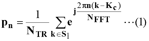
ただし、nは時間に対応したアドレス、Slはリザーブド・トーン用に用意されたアドレスの集合、NTRはリザーブド・トーンの数、Kcはサブキャリアの中央のアドレスである。この演算によって得られたカーネル信号列は、アドレス“0”において振幅の最大ピーク値“1”を取る。
ピーク検出部301は、NFFT個の値を持つデータ信号列のうち、振幅値の最大を取るアドレスと、そのアドレスにおけるデータ値を検出して出力する。そのアドレスをm(1)とした時、信号xm(1)の振幅|xm(1)|が閾値Vclipを超えていた場合、下記の数式(2)~(4)の通り、シフト・スケーリング部302で、時間シフト{(n-m(1)) mod NFFT}と振幅スケーリングα(1)と位相スケーリングu(1)とを行ったカーネル信号列α(1)u(1)p(n-m(1)) mod NFFT)を出力する。減算部303において、データ信号列xnから減算することにより、アドレスm(1)での振幅ピークを抑制したデータ信号列xn(1)が得られる。


この演算によって得られたデータ信号列xn(1)は、元のデータ信号列x_nからシフトとスケーリングされたカーネル信号列の減算によって得られるので、周波数成分はリザーブド・トーン以外変化しない特徴を持つ。
さらに、上記のピーク検出および抑制演算を、下記のとおり繰り返し行うことにより、i反復後にi個のピークが抑制されたデータ信号列xn(i)が得られて、PAPRの大幅な抑制が実現される。


この反復演算は、反復回数iがあらかじめ定められた反復限界回数に達するまで実行されて、反復演算終了後に、PAPRが抑制された1シンボル分のデータ信号列が出力される。
ただ、GBAの欠点としては、反復回数の増加に伴い、リザーブド・トーンの値が増加することが挙げられる。TR後のリザーブド・トーンの値には上限があり、例えば、地上デジタル放送の変調規格DVB-T2においては、非特許文献4に記載される通り、リザーブド・トーンのパワーがリザーブド・トーン以外のサブキャリアのパワーと比べて10倍以内に抑えるように制限されている。よって、上記アルゴリズムをそのまま適用した場合、規格を満たさなくなるケースがある。
(TRアルゴリズムの概要)
この問題に対して、ETSI記載のガイドラインでは、GBAを改良したアルゴリズムが提案されている。このアルゴリズムは、基本的にはGBAをベースとしており、数式(5)および数式(7)に基づいて、データ信号列の更新が行われている。ただし、振幅スケーリング値α(i)の決定方法が数式(6)と異なっており、データ信号列の値を更新する度に、対応するリザーブド・トーンの値を更新した上で、その値はカーネル信号列の振幅スケーリング値α(i)の決定に反映される。以下にその動作説明を行う。
この問題に対して、ETSI記載のガイドラインでは、GBAを改良したアルゴリズムが提案されている。このアルゴリズムは、基本的にはGBAをベースとしており、数式(5)および数式(7)に基づいて、データ信号列の更新が行われている。ただし、振幅スケーリング値α(i)の決定方法が数式(6)と異なっており、データ信号列の値を更新する度に、対応するリザーブド・トーンの値を更新した上で、その値はカーネル信号列の振幅スケーリング値α(i)の決定に反映される。以下にその動作説明を行う。
図4Aは、前提技術のTR400の構成を示す図である。
反復演算の初めに、1シンボル分のカーネル信号列はカーネルキャッシュ401に、1シンボル分のデータ信号列はシンボルキャッシュ402に蓄積される。リザーブド・トーン・キャッシュ(図中は、reserved toneキャッシュ)405には、データ信号列のリザーブド・トーンの周波数成分が蓄積されており、初期状態は全て“0”と設定されている。
シンボルキャッシュ402は、GBAの反復が実行されるごとに、各々更新されたデータ信号列が上書きされる。それに対応して、リザーブド・トーン・キャッシュ405の値は、シフト・スケーリング部404で反復に使用されたシフト量とスケーリング量とを元に、リザーブド・トーン更新演算部(図中は、reserved tone更新演算部)406で算出されたリザーブド・トーン成分の更新値を減算した上で、上書きされる。
以下、i反復目の演算の流れについて、詳細に説明する。
ピーク検出部403は、入力されたデータ信号列xn(i-1)のピーク値を取るアドレスm(i)とそのアドレスにおけるデータ値xm(i)(i-1)を算出して、シフト・スケーリング部404にその値を入力する。
シフト・スケーリング部404は、リザーブド・トーン・キャッシュ405の値rk(i-1)と、ピークを取るデータ信号列のアドレスm(i)とそのアドレスにおけるデータ値xm(i)(i-1)を元に、振幅スケーリング値α(i)と位相スケーリング値u(i)とを算出して出力する。同時に、シフト・スケーリング部404は、スケーリング値および時間シフト値をカーネルキャッシュ401から出力されたカーネル信号列pnに作用させた信号列α(i)u(i)p((n-m(i)) mod NFFT)を算出して、ピーク抑制信号列として出力する。
さらに、シンボル減算部407は、数式(5)に従って、シンボルキャッシュ402から読み出されたデータ信号列から、シフト・スケーリング部404より出力された信号列α(i)u(i)p((n-m(i)) mod NFFT)を減算して更新後のデータ信号列xn(i)を算出して出力する。
なお、位相スケーリング値u(i)に関しては数式(7)と同じ演算により算出される。
振幅スケーリング値α(i)は数式(6)とは異なり、反復後にリザーブド・トーンの値が規定値を超えないような値を算出する工夫を行う。具体的には以下の数式(8)~(10)で算出されるスケーリング値α(i)を用いる。
振幅スケーリング値α(i)は数式(6)とは異なり、反復後にリザーブド・トーンの値が規定値を超えないような値を算出する工夫を行う。具体的には以下の数式(8)~(10)で算出されるスケーリング値α(i)を用いる。



これらの演算により、データ信号列がxn(i-1)からxn(i)に更新されて、シンボルキャッシュ402に上書きされると同時に、ピーク検出部403の次の入力としてデータ信号列xn(i)が入力される。
リザーブド・トーン更新演算部406では、シフト・スケーリング部404の演算過程で振幅スケーリング値α(i)と位相スケーリング値u(i)とピークアドレスm(i)とが得られる。これらを元に、リザーブド・トーンの更新値α(i)vk(i)(vk(i)は、数式(8)の演算で算出される値である。リザーブド・トーン更新演算部406は、数式(8)の演算時に値を記憶しておき、再利用することも可能)を算出する。
リザーブド・トーン減算部408は、リザーブド・トーン・キャッシュ405の値から、リザーブド・トーン更新演算部406で得られた値を、数式(11)の通り減算することにより、リザーブド・トーン・キャッシュ405の値をrk(i-1)からrk(i)に更新する。

このような手順によって反復演算を実行することにより、リザーブド・トーンの値を規定値以下に抑えたまま、PAPRの抑制が実現される。
(シフト・スケーリング部)
図4Bは、前提技術のシフト・スケーリング部404の構成を示すブロック図である。
図4Bは、前提技術のシフト・スケーリング部404の構成を示すブロック図である。
シフト・スケーリング部404は、シンボル減算部407への規定値以内のピーク抑制のための減算値を生成する演算部441と、演算部441およびリザーブド・トーン更新演算部406が使用するスケーリング値を算出する演算部442と、を有する。
演算部441は、ピーク検出部403からのアドレス(m(i))に基づくシフト値{(n-m(1)) mod NFFT}と、カーネルキャッシュ401からのカーネル信号列(pn)と、演算部442からのスケーリング値(α(i)、u(i))とから、規定値以内のピーク抑制のための減算値(数式(5)参照)をピーク抑制信号列として算出する。そして、演算部441は、シンボル減算部407に減算値を出力する。
演算部442は、データ信号列xnの振幅を判定する閾値Vclipの記憶部442aを有する。演算部442は、リザーブド・トーン・キャッシュ405からのリザーブド・トーンの周波数成分(rk(i-1))やピーク検出部403からのアドレス(m(i))に基づき、数式(7)~(10)に従って、スケーリング値(α(i)、u(i))を算出する。そして、演算部442は、演算部441およびリザーブド・トーン更新演算部406にスケーリング値(α(i)、u(i))を出力する。
ところで、上述のETSI提案のTR400の方式では、反復途中でリザーブド・トーンを保持するキャッシュ(NTR個のデータ列)の値が1つでも規定値に達してしまった場合、それ以降の反復において、振幅スケーリング値が“0”となってしまう。これにより、以降の反復は実質的には行われなくなってしまい、十分な反復が実行できず、その結果、データ信号列の十分なPAPR抑制量が得られない。
本実施形態は、かかる課題を解決して、トーンリザベーションにおいてリザーブド・トーンの周波数成分を規定値に抑えた上で、データ信号列のPAPR抑制量を最大化する、以下のようなピーク抑制回路およびピーク抑制回路を使用するOFDM変調器を提案する。
《本実施形態のピーク抑制回路の構成》
図2Aは、本実施形態に係るピーク抑制回路200の構成を示すブロック図である。
図2Aは、本実施形態に係るピーク抑制回路200の構成を示すブロック図である。
本実施形態のピーク抑制回路200は、トーンリザベーション実行部(図中は、Tone Reservation実行部)201とリザーブド・トーン抑制部(図中は、reserved Tone抑制部)202とを備える。
(トーンリザベーション実行部)
トーンリザベーション実行部201は、時系列のデータ信号列(xn)とリザーブド・トーンの周波数成分に値を持つ時系列のカーネル信号列(pn)とを入力として、トーンリザベーションを実行することにより、ピーク抑制後のデータ信号列(x'n)を出力する。この時、トーンリザベーション実行部201に入力されるカーネル信号列およびデータ信号列は、それぞれ前段のOFDM変調において逆フーリエ変換して得られた信号を直接用いるのではなく、それらを補間した信号を入力としてもよい。これは、本実施形態には限定されず、以降の実施形態においても、同様に適用される。
トーンリザベーション実行部201は、時系列のデータ信号列(xn)とリザーブド・トーンの周波数成分に値を持つ時系列のカーネル信号列(pn)とを入力として、トーンリザベーションを実行することにより、ピーク抑制後のデータ信号列(x'n)を出力する。この時、トーンリザベーション実行部201に入力されるカーネル信号列およびデータ信号列は、それぞれ前段のOFDM変調において逆フーリエ変換して得られた信号を直接用いるのではなく、それらを補間した信号を入力としてもよい。これは、本実施形態には限定されず、以降の実施形態においても、同様に適用される。
トーンリザベーション実行部201は、カーネルキャッシュ211と、シンボルキャッシュ212と、ピーク検出部213と、シフト・スケーリング部214と、リザーブド・トーン・キャッシュ215と、リザーブド・トーン更新演算部216と、シンボル減算部217と、リザーブド・トーン減算部218と、を備える。
反復演算の開始時点で、カーネル信号列の値はカーネルキャッシュ211に蓄積され、データ信号列の値はシンボルキャッシュ212に蓄積される。また、リザーブド・トーン・キャッシュ215には、データ信号列のリザーブド・トーンの周波数成分が蓄積されており、初期状態は全て“0”と設定されている。
以下,i反復目の動作について説明する。なお,記号の定義等に関しては、背景技術に記された定義を踏襲する。
ピーク検出部213は、入力されたデータ信号列xn(i-1)のピーク値を取るアドレスm(i)と、そのアドレスにおけるデータ値xm(i)(i-1)を算出して、シフト・スケーリング部214に出力する。
(シフト・スケーリング部)
シフト・スケーリング部214は、データ信号列のアドレスm(i)と、そのアドレスにおけるデータ値xm(i)(i-1)と、振幅スケーリング値α(i)と、位相スケーリング値u(i)とを算出して出力する。同時に、シフト・スケーリング部214は、カーネルキャッシュ211から読み出されたカーネル信号列pnに、時間シフト値とスケーリング値とを作用させた信号列α(i)u(i)p((n-m(i)) mod NFFT)をピーク抑制信号列として出力する。なお、振幅スケーリング値α(i)に関しては数式(6)と、位相スケーリング値u(i)に関しては数式(7)と同じ演算により算出される。
シフト・スケーリング部214は、データ信号列のアドレスm(i)と、そのアドレスにおけるデータ値xm(i)(i-1)と、振幅スケーリング値α(i)と、位相スケーリング値u(i)とを算出して出力する。同時に、シフト・スケーリング部214は、カーネルキャッシュ211から読み出されたカーネル信号列pnに、時間シフト値とスケーリング値とを作用させた信号列α(i)u(i)p((n-m(i)) mod NFFT)をピーク抑制信号列として出力する。なお、振幅スケーリング値α(i)に関しては数式(6)と、位相スケーリング値u(i)に関しては数式(7)と同じ演算により算出される。
すなわち、トーンリザベーション実行部201のシフト・スケーリング部214は、リザーブド・トーン・キャッシュ215に記憶されたリザーブド・トーンの値による抑制を受けない。したがって、反復途中でリザーブド・トーンを保持するキャッシュ(NTR個のデータ列)の値が規定値に達したとしても、それ以降の反復は継続され、その結果、データ信号列の十分なPAPR抑制量が得られる。
図2Bは、本実施形態に係るシフト・スケーリング部214の構成を示すブロック図である。
シフト・スケーリング部214は、シンボル減算部217へのリザーブド・トーンに応じた抑制なしにピーク抑制のための減算値を生成する演算部241と、演算部241およびリザーブド・トーン更新演算部216が使用するスケーリング値を算出する演算部242と、を有する。
演算部241には、ピーク検出部213からアドレス(m(i))に基づくシフト値{(n-m(1)) mod NFFT}が入力され、カーネルキャッシュ211からカーネル信号列(pn)が入力され、演算部242からスケーリング値(α(i)、u(i))が入力される。演算部241はこれらから、リザーブド・トーンに応じた抑制なしにピーク抑制のための減算値(数式(5)参照)をピーク抑制信号列として算出する。そして、演算部241は、シンボル減算部217に減算値を出力する。
演算部242は、データ信号列xnの振幅を判定する閾値Vclipの記憶部242aを有する。なお、閾値Vclipは外部から入力されてもよい。演算部242は、ピーク検出部213からのアドレス(m(i))に基づき、数式(6)および(7)に従って、スケーリング値(α(i)、u(i))を算出する。そして、演算部242は、演算部241およびリザーブド・トーン更新演算部216にスケーリング値(α(i)、u(i))を出力する。
なお、シフト・スケーリング部214のうち、時間シフトに関しては、カーネルキャッシュ211からデータの読み出しを開始するアドレスを調整することによって実現できる。この場合、ピーク検出部213から出力されるピークアドレスm(i)がカーネルキャッシュ211に入力されて、それに基づいて読み出し開始位置を調整する。具体的には、通常読み出し開始位置をアドレス“0”とするところを、{NFFT-m(i)}からスタートして逐次読み出しを行い、読み出しアドレスが{NFFT-1}に到達したら“0”に戻ってまた逐次読み出しを続ければ、時間シフトp((n-m(i)) mod NFFT)が実現される。こういった構成も本実施形態に含まれる。
シンボル減算部217は、シンボルキャッシュ212から読み出されたデータ信号列xn(i-1)から、シフト・スケーリング部214で時間シフトとスケーリングとを行ったカーネル信号列α(i)u(i)p((n-m(i)) mod NFFT)を減算(数式(5)参照)することにより、データ信号列の更新(xn(i-1)⇒xn(i))を行う。
リザーブド・トーン更新演算部216は、シフト・スケーリング部214から出力される振幅スケーリング値α(i)と、位相スケーリング値u(i)と、ピークアドレスm(i)とを入力として、数式(8)の演算を行うことで、リザーブド・トーンの更新値列α(i)vk(i)を出力する。
リザーブド・トーン減算部218は、リザーブド・トーン・キャッシュ215から読み出されるリザーブド・トーンの値列rk(i-1)から、リザーブド・トーン更新演算部216から出力されるリザーブド・トーンの更新値列α(i)vk(i)を減算(数式(8)参照)することにより、リザーブド・トーンの値列をrk(i-1)からrk(i)に更新する。
更新されたデータ信号列xn(i)は、反復回数iが限界反復回数の場合、トーンリザベーション実行部201の出力信号として出力され、そうでない場合は、シンボルキャッシュ212に上書きされると同時に、ピーク検出部213に入力されて、次の反復演算が開始される。
(リザーブド・トーン抑制部)
リザーブド・トーン抑制部202は、トーン処理部(図中は、tone処理部)221と、IDFT部(逆フーリエ変換部)222と、減算部223と、を有する。
リザーブド・トーン抑制部202は、トーン処理部(図中は、tone処理部)221と、IDFT部(逆フーリエ変換部)222と、減算部223と、を有する。
トーン処理部221は、ピーク抑制後のデータ信号列のリザーブド・トーンの周波数成分を入力として、規定値を超えた成分を抑制する周波数データ列を作成する。IDFT部222は、トーン処理部の出力である周波数データ列を逆フーリエ変換することにより、時系列データに変換する。減算部223は、ピーク抑制後のデータ信号列からIDFT部222の出力信号を減算して出力する。
(トーン処理部)
図2Cは、本実施形態に係るトーン処理部221の構成を示すブロック図である。
図2Cは、本実施形態に係るトーン処理部221の構成を示すブロック図である。
トーン処理部221の具体的な処理方法の例としては、ある規定値Amaxを超えた分だけクリップして抽出する方法がある。トーン処理部221は、ピーク抑制後のデータ信号列をxnのリザーブド・トーンの周波数成分をrk(kは、リザーブド・トーン周波数に対応したアドレス)を取得し、リザーブド・トーン周波数の値wkを以下の数式(12)により算出する。

この値wkを、IDFT部222で、数式(13)により時系列データcnに変換した上で、減算部223で、数式(14)のように、ピーク抑制後のデータ信号列xnから減算することにより、リザーブド・トーンの値が規定値以内に収まった、ピーク抑制後のデータ信号列ynが得られる。


なお、トーン処理部221の処理方法に関しては、数式(12)に限定されず、以下の数式(15)および(16)のように、スケーリング値を適正に選ぶことで、リザーブド・トーン抑制を行う方法も考えられる。


なお、ここで提案したトーン処理部の処理方法に関しては、本実施形態には限定されず、以降の実施形態においても、同様に適用される。また、IDFT部222においては、逆フーリエ高速変換(IFFT)など、演算を高速化する演算が用いられてもよい。
《OFDM変調器》
図2Dは、本実施形態に係るピーク抑制回路200を使用するOFDM変調器250の構成を示すブロック図である。なお、図2DはOFDM変調器250の一例であってこの構成に限定されない。また、本実施形態に係るピーク抑制回路200はOFDM復調器に適用されることも可能である。
図2Dは、本実施形態に係るピーク抑制回路200を使用するOFDM変調器250の構成を示すブロック図である。なお、図2DはOFDM変調器250の一例であってこの構成に限定されない。また、本実施形態に係るピーク抑制回路200はOFDM復調器に適用されることも可能である。
OFDM変調器250は、データ信号列マッピング部251と、直並変換部252と、サブキャリアマッピング部253と、IFFT部254と、本実施形態のピーク抑制回路200と、ガードインターバル挿入部256と、並直変換部257と、を備える。
データ信号列マッピング部251は、変調方式に従って、入力ビット列をベクトルで表わされるシンボルにマッピングする。直並変換部252は、直列のシンボルを並列に変換し、サブキャリアマッピング部253は、並列のシンボルの種類に応じて位相や振幅が設定された複数のサブキャリアによりシンボルを並列に伝送する。そして、IFFT部254により並列のシンボルが合成されてOFDM信号が生成される。しかしながら、IFFT部254におけるシンボルの組み合わせによっては非常に大きなピークが発生する。
本実施形態のピーク抑制回路200は、トーンリザベーションによりかかるピークを確実に抑制すると共に、リザーブド・トーンの規定値以下への抑制を実現する。ガードインターバル挿入部256は、複数の多重伝送データが前後の時間のデータとお互いに干渉しないように、ガードインターバル用符号を挿入する。並直変換部257は、並列の多重伝送データを直列に変換して出力ビット列を生成する。
《ピーク抑制処理の手順》
本実施形態のピーク抑制回路は、以下の手順に従ったプロセッサによるピーク抑制処理によっても実現が可能である。
本実施形態のピーク抑制回路は、以下の手順に従ったプロセッサによるピーク抑制処理によっても実現が可能である。
図5Aは、本実施形態に係るピーク抑制回路200の処理手順を示すフローチャートである。
ピーク抑制回路200は、ステップS501において、更新されるリザーブド・トーンに応じた抑制なしのトーンリザベーション処理を実行する。そして、ピーク抑制回路200は、ステップS503において、トーンリザベーション結果に対応するリザーブド・トーンの周波数成分を用いてリザーブド・トーン抑制処理を実行する。
(トーンリザベーション処理)
図5Bは、本実施形態に係るトーンリザベーション処理(S501)の手順を示すフローチャートである。
図5Bは、本実施形態に係るトーンリザベーション処理(S501)の手順を示すフローチャートである。
ピーク抑制回路200は、ステップS511において、データ信号列xnとカーネル信号列pnとを取得して保持する。ピーク抑制回路200は、ステップS513において、データ信号列のピークを検出する。なお、ピークを検出する対象は、1反復目はステップS511において取得したデータ信号列であり、ステップS523からの反復中は更新したデータ信号列である。
ピーク抑制回路200は、ステップS515において、ピーク検出結果(アドレス,そのアドレスにおけるデータ値)と、振幅値の閾値Vclipとに基づいて、時間シフト値、振幅スケーリング値および位相スケーリング値を算出する。ピーク抑制回路200は、ステップS517において、カーネル信号列pnに対して、時間シフト、振幅スケーリングおよび位相スケーリングを行ない、ピーク抑制信号列を生成する。ピーク抑制回路200は、ステップS519において、データ信号列xn(i-1)から、シフトおよびスケーリングしたカーネル信号列を減算して、振幅ピークを抑制したデータ信号列xn(i)に更新する。ピーク抑制回路200は、ステップS521において、アドレス、振幅スケーリング値および位相スケーリング値に基づいてリザーブド・トーン値を更新してキャッシュに記憶する。
ピーク抑制回路200は、ステップS523において、反復回数が限界回数に到達したか否かを判定する。反復回数が限界回数に到達してなければ、ピーク抑制回路200は、ステップS513に戻って、振幅ピークを抑制したデータ信号列xn(i)の更新を反復する。反復回数が限界回数に到達すれば、ピーク抑制回路200は、ステップS525において、ピークを抑制したデータ信号列x'nを出力してリターンする。
(リザーブド・トーン抑制処理)
図5Cは、本実施形態に係るリザーブド・トーン抑制処理(S503)の手順を示すフローチャートである。
図5Cは、本実施形態に係るリザーブド・トーン抑制処理(S503)の手順を示すフローチャートである。
ピーク抑制回路200は、ステップS531において、ピークを抑制したデータ信号列x'nと、データ信号列x'nに対応するリザーブド・トーンの周波数成分rkとを取得する。ピーク抑制回路200は、ステップS533において、規定値Amaxを超えた成分を抑制する周波数データ列wkを生成する。ピーク抑制回路200は、ステップS535において、周波数データ列wkを逆フーリエ変換して、時系列データcnを生成する。そして、ピーク抑制回路200は、ステップS537において、ピークを抑制したデータ信号列x'nから時系列データcnを減算して、リザーブド・トーンの値が規定値Amax以内に収まった、ピーク抑圧後のデータ信号列ynを出力する。
以上のように、本実施形態によれば、リザーブド・トーンの値が規定値以内に収まり、かつ、ピークが抑制されたOFDMのデータ信号列が得られる。
[第3実施形態]
次に、本発明の第3実施形態に係るピーク抑制回路について説明する。本実施形態に係るピーク抑制回路は、上記第2実施形態と比べると、トーンリザベーション部が複数ピーク検出部と複数のシフト・スケーリング部とを有する点で異なる。その他の構成および動作は、第2実施形態と同様であるため、同じ構成および動作については同じ符号を付してその詳しい説明を省略する。
次に、本発明の第3実施形態に係るピーク抑制回路について説明する。本実施形態に係るピーク抑制回路は、上記第2実施形態と比べると、トーンリザベーション部が複数ピーク検出部と複数のシフト・スケーリング部とを有する点で異なる。その他の構成および動作は、第2実施形態と同様であるため、同じ構成および動作については同じ符号を付してその詳しい説明を省略する。
《本実施形態のピーク抑制回路の構成》
図6は、本実施形態に係るピーク抑制回路600の構成を示すブロック図である。なお、図6において、図2Aと同様の構成要素には同じ参照番号を付して、説明は省略する。
図6は、本実施形態に係るピーク抑制回路600の構成を示すブロック図である。なお、図6において、図2Aと同様の構成要素には同じ参照番号を付して、説明は省略する。
本実施形態のピーク抑制回路600は、トーンリザベーション実行部601とリザーブド・トーン抑制部202とを備える。トーンリザベーション実行部601は、カーネルキャッシュ211と、シンボルキャッシュ212と、複数ピーク検出部613と、第1から第qのシフト・スケーリング部6141~614qと、リザーブド・トーン・キャッシュ215を備える。またトーンリザベーション実行部601は、リザーブド・トーン更新演算部616と、シンボル減算部617と、リザーブド・トーン減算部618と、を有する。リザーブド・トーン抑制部202は、トーン処理部221と、IDFT部222と、減算部223と、を有する。
以下、トーンリザベーション実行部601のi反復目の動作について説明する。なお、以下に記される記号の定義等に関しては、背景技術に記された定義を踏襲する。
複数ピーク検出部613は、入力されたデータ信号列xn(i-1)の中からq個の振幅ピーク値を取るアドレスms(i)(1≦s≦q)と、そのアドレスにおけるデータ値xms(i)(i-1)を算出して、第sのシフト・スケーリング部614s(1≦s≦q)に、アドレスとそのアドレスにおけるデータ値とを対として出力する。ここで、qはあらかじめ指定された数である。
第sのシフト・スケーリング部614s(1≦s≦q)は、データ信号列のアドレスms(i)とそのアドレスにおけるデータ値xms(i)(i-1)とを入力として、振幅スケーリング値αs(i)と位相スケーリング値us(i)を算出して出力する。同時に、第sのシフト・スケーリング部614s(1≦s≦q)は、カーネルキャッシュ211から読み出されたカーネル信号列pnに時間シフト値とスケーリング値とを作用させた信号列αs(i)us(i)p((n-ms(i)) mod NFFT)をピーク抑制信号列として出力する。なお、振幅スケーリング値αs(i)は下記数式(17)の演算で、位相スケーリング値us(i)に関しては数式(18)の演算によって得られる。


複数ピーク検出部613における具体的なピーク検出方法としては、例えば、NFFT個のデータ信号列xn(i-1)をq分割して、それぞれの領域において、最大ピーク値となるアドレスとそのアドレスにおけるデータ値とを検出する方法がある。また、振幅の極大値(|x(j-1)
(i-1)|<|xj
(i-1)|、かつ、|xj
(i-1)|>|x(j+1)
(i-1)|)を取るアドレスを列挙した上で、その中で振幅値が大きいものから順にq個選び、それらのアドレスとそのアドレスにおけるデータ値とを出力とする方法などがある。なお、複数ピーク検出方法は、これら2種類に限定されない。
シンボル減算部617は、シンボルキャッシュ212から読み出されたデータ信号列xn(i-1)から、第sのシフト・スケーリング部614sの出力である、時間シフトとスケーリングとを行ったカーネル信号列αs(i)us(i)p((n-ms(i)) mod NFFT)のq個分を下記数式(19)の通り減算して、データ信号列の更新(xn(i-1)⇒xn(i))を行う。

リザーブド・トーン更新演算部616は、シフト・スケーリング部614sから出力される振幅スケーリング値αs(i)と、位相スケーリング値us(i)と、ピークアドレスms(i)を入力として、下記数式(20)の演算を行うことでリザーブド・トーンの更新値列αs(i)v(k,s)(i)を出力する。

さらに、リザーブド・トーン減算部618は、リザーブド・トーン・キャッシュ215から出力されるリザーブド・トーンの値列rk(i-1)から、リザーブド・トーン更新演算部616の出力であるαs(i)v(k,s)(i)のq個分を減算することにより、下記数式(21)の通りリザーブド・トーンの値列をrk(i-1)からrk(i)に更新する。

更新されたデータ信号列xn(i)は、反復回数iが限界反復回数の場合、トーンリザベーション実行部601の出力信号として出力され、そうでない場合は、シンボルキャッシュ212に上書きされると同時に、複数ピーク検出部613に入力されて、次の反復演算が開始される。
なお、第sのシフト・スケーリング部614sのうち、時間シフトに関してはカーネルキャッシュ211からデータの読み出しを開始するアドレスを調整することによって実現できる。この場合、複数ピーク検出部613から第sのシフト・スケーリング部614sに出力されるピークアドレスms(i)がカーネルキャッシュ211に入力されて、それに基づいて読み出し開始位置を調整する。具体的には、通常読み出し開始位置をアドレス“0”とするところを、{NFFT-ms(i)}からスタートして逐次読み出しを行い、アドレスが{NFFT-1}に到達したら“0”に戻ってそこからまた逐次読み出しつづければ、時間シフトp((n-ms(i)) mod NFFT)が実現される。こういった構成も本実施形態に含まれる。
本実施形態によれば、複数ピークを検出して複数のシフト・スケーリング部によりピーク抑制を行なうので、より少ない反復回数により確実なピーク抑制ができる。したがって、OFDM変調が高速にできる。
[第4実施形態]
次に、本発明の第4実施形態に係るピーク抑制回路について説明する。本実施形態に係るピーク抑制回路は、上記第2実施形態および第3実施形態と比べると、リザーブド・トーン抑制部が使用するリザーブド・トーンの周波数成分を、ピーク抑制後のデータ信号列をフーリエ変換することにより生成する点で異なる。その他の構成および動作は、第2実施形態や第3実施形態と同様であるため、同じ構成および動作については同じ符号を付してその詳しい説明を省略する。
次に、本発明の第4実施形態に係るピーク抑制回路について説明する。本実施形態に係るピーク抑制回路は、上記第2実施形態および第3実施形態と比べると、リザーブド・トーン抑制部が使用するリザーブド・トーンの周波数成分を、ピーク抑制後のデータ信号列をフーリエ変換することにより生成する点で異なる。その他の構成および動作は、第2実施形態や第3実施形態と同様であるため、同じ構成および動作については同じ符号を付してその詳しい説明を省略する。
《本実施形態のピーク抑制回路の構成》
図7は、本実施形態に係るピーク抑制回路700の構成を示すブロック図である。図7において、図2Aと同様の構成要素には同じ参照番号を付して、説明を省略する。
図7は、本実施形態に係るピーク抑制回路700の構成を示すブロック図である。図7において、図2Aと同様の構成要素には同じ参照番号を付して、説明を省略する。
図7において、リザーブド・トーン抑制部202のトーン処理部221に入力される、リザーブド・トーンの周波数成分は、ピーク抑制後のデータ信号列x'nをDFT部703でフーリエ変換することにより生成される。この構成は、ピーク抑制後のデータ信号列のリザーブド・トーンの周波数成分がトーンリザベーション実行部201において算出されない場合の構成である。
なお、DFT部703においては高速フーリエ変換(FFT)など、演算を高速化する演算が用いられてもよい。また、トーンリザベーション実行部201はトーンリザベーション実行部601に置き換えられてもよい。また、トーンリザベーション実行部で生成されたリザーブド・トーンの周波数成分と、ピーク抑制されたデータ信号列に対してDFT部703においてフーリエ変換した結果とを、切り替えて使用する構成も、本実施形態に含まれる。
本実施形態によれば、トーンリザベーション実行部がリザーブド・トーンの周波数成分を算出しない場合においても、リザーブド・トーンの周波数成分を規定値に抑えた上で、データ信号列のPAPR抑制量を最大化することができる。そのため、本発明を無線送信機に適用することにより、電力効率が高い送信機を提供することができる。
[第5実施形態]
次に、本発明の第5実施形態に係るピーク抑制回路について説明する。本実施形態に係るピーク抑制回路は、上記第2実施形態乃至第4実施形態と比べると、トーンリザベーション実行部の構成が異なる。その他の構成および動作は、第2実施形態から第4実施形態と同様であるため、同じ構成および動作については同じ符号を付してその詳しい説明を省略する。
次に、本発明の第5実施形態に係るピーク抑制回路について説明する。本実施形態に係るピーク抑制回路は、上記第2実施形態乃至第4実施形態と比べると、トーンリザベーション実行部の構成が異なる。その他の構成および動作は、第2実施形態から第4実施形態と同様であるため、同じ構成および動作については同じ符号を付してその詳しい説明を省略する。
《本実施形態のピーク抑制回路の構成》
図8Aは、本実施形態に係るピーク抑制回路800の構成を示すブロック図である。なお、図8Aにおいて、図2Aと同様の構成要素には同じ参照番号を付して、説明を省略する。
図8Aは、本実施形態に係るピーク抑制回路800の構成を示すブロック図である。なお、図8Aにおいて、図2Aと同様の構成要素には同じ参照番号を付して、説明を省略する。
本実施形態のピーク抑制回路800は、トーンリザベーション実行部(図中は、Tone Reservation実行部)801とリザーブド・トーン抑制部(図中は、reserved Tone抑制部)202とを備える。
(トーンリザベーション実行部)
本実施形態のトーンリザベーション実行部801は、複数カーネルキャッシュ811と、シンボルキャッシュ212と、ピーク検出部213と、スケーリング部814と、リザーブド・トーン・キャッシュ215と、リザーブド・トーン更新演算部216と、シンボル減算部217と、リザーブド・トーン減算部218と、を備える。
本実施形態のトーンリザベーション実行部801は、複数カーネルキャッシュ811と、シンボルキャッシュ212と、ピーク検出部213と、スケーリング部814と、リザーブド・トーン・キャッシュ215と、リザーブド・トーン更新演算部216と、シンボル減算部217と、リザーブド・トーン減算部218と、を備える。
反復演算の開始時点で、複数のカーネル信号列の値は、複数カーネルキャッシュ811に蓄積され、データ信号列の値はシンボルキャッシュ212に蓄積される。この複数のカーネル信号列は、例えば、リザーブド・トーンの値があるアドレスにおいて“1”の値を持ち、それ以外では“0”の値を持つ周波数成分を逆フーリエ変換して得られる信号列によって構成されており、式で表すと数式(22)の通りになる。

なお、これ以外にも、カーネル信号列の組を生成する方法は存在しており、カーネル信号列の組を生成する方法は上記に限定しない。また、リザーブド・トーン・キャッシュ215には、データ信号列のリザーブド・トーンの周波数成分が蓄積されており、初期状態は全て“0”と設定されている。
以下,i反復目の動作について説明する。なお,記号の定義等に関しては、背景技術に記された定義を踏襲する。
ピーク検出部213は、入力されたデータ信号列xn(i-1)のピーク値を取るアドレスm(i)と、そのアドレスにおける値xm(i)(i-1)を算出して、スケーリング部814に出力する。
スケーリング部814は、データ信号列のアドレスm(i)と、そのアドレスにおける値xm(i)(i-1)から、振幅スケーリング値α(i)と、位相スケーリング値u(i)とを算出して出力する。同時に、スケーリング部814は、複数カーネルキャッシュ811から読み出されたカーネル信号列pnk(i)に、スケーリング値を作用させた信号列α(i)u(i)pnk(i)をピーク抑制信号列として出力する。なお、振幅スケーリング値α(i)に関しては数式(6)と、位相スケーリング値u(i)に関しては数式(7)と同じ演算により算出される。
なお、複数カーネルキャッシュ811から読み出されるカーネル信号列pnk(i)の列番k(i)は、データ信号列のアドレスm(i)と、そのアドレスにおける値xm(i)(i-1)を用いて決定される。例えば、各カーネル信号列のアドレスm(i)における振幅値を比べて、最大値を取る列番が選択される。それ以外にも、後述のスケーリング部814において位相スケーリングの演算を省くために、アドレスm(i)における位相値がxm(i)(i-1)の位相値に一番近い列番を選択する方法などもある。また、上記2種類の決定方法を組み合わせた方法や、m(i)とxm(i)(i-1)を用いずに、反復ごとに順番に列番を選択する方法なども含まれる。
すなわち、トーンリザベーション実行部801のスケーリング部814は、リザーブド・トーン・キャッシュ215に記憶されたリザーブド・トーンの値による抑制を受けない。したがって、反復途中でリザーブド・トーンを保持するキャッシュ(NTR個のデータ列)の値が規定値に達したとしても、それ以降の反復は継続され、その結果、データ信号列の十分なPAPR抑制量が得られる。
(スケーリング部)
図8Bは、本実施形態に係るスケーリング部814の構成を示すブロック図である。なお、図8Bにおいて、図2Bと同様の構成要素には同じ参照番号を付して、説明を省略する。
図8Bは、本実施形態に係るスケーリング部814の構成を示すブロック図である。なお、図8Bにおいて、図2Bと同様の構成要素には同じ参照番号を付して、説明を省略する。
スケーリング部814は、シンボル減算部217へのリザーブド・トーンに応じた抑制なしにピーク抑制のための減算値を生成する演算部841と、演算部841およびリザーブド・トーン更新演算部216が使用するスケーリング値を算出する演算部242と、を有する。
演算部841は、複数カーネルキャッシュ811からのカーネル信号列(pnk(i))と、演算部242からのスケーリング値(α(i)、u(i))とから、リザーブド・トーンに応じた抑制なしにピーク抑制のための減算値であるα(i)u(i)pnk(i)(なお、このケースではm(i)=0)をピーク抑制信号列として算出する。そして、演算部841は、シンボル減算部217に減算値を出力する。
シンボル減算部217は、シンボルキャッシュ212から読み出されたデータ信号列xn(i-1)から、スケーリング部814でスケーリングを行ったカーネル信号列α(i)u(i)pnk(i)を減算(数式(5)参照)することにより、データ信号列の更新(xn(i-1)⇒xn(i))を行う。
リザーブド・トーン更新演算部216は、スケーリング部814から出力される振幅スケーリング値α(i)と、位相スケーリング値u(i)と、ピークアドレスm(i)とを入力として、数式(8)(このケースではm(i)=0)の演算を行うことで、リザーブド・トーンの更新値列α(i)vk(i)を出力する
更新されたデータ信号列xn(i)は、反復回数iが限界反復回数の場合、トーンリザベーション実行部801の出力信号として出力され、そうでない場合は、シンボルキャッシュ212に上書きされると同時に、ピーク検出部213に入力されて、次の反復演算が開始される。
(リザーブド・トーン抑制部)
リザーブド・トーン抑制部202は、図2Aと同様に、トーン処理部(図中は、tone処理部)221と、IDFT部(逆フーリエ変換部)222と、減算部223と、を有し、ピーク抑制後のデータ信号列のリザーブド・トーンの周波数成分を入力として、ピーク抑制後のデータ信号列における規定値を超えた成分を抑制する。
リザーブド・トーン抑制部202は、図2Aと同様に、トーン処理部(図中は、tone処理部)221と、IDFT部(逆フーリエ変換部)222と、減算部223と、を有し、ピーク抑制後のデータ信号列のリザーブド・トーンの周波数成分を入力として、ピーク抑制後のデータ信号列における規定値を超えた成分を抑制する。
なお、図8Aにおいては、図2Aのように、リザーブド・トーン抑制部202に対してピーク抑制後のデータ信号列のリザーブド・トーンの周波数成分を入力したが、図7のように、リザーブド・トーンの周波数成分を、ピーク抑制後のデータ信号列をフーリエ変換することにより生成してもよい。
本実施形態によれば、異なるトーンリザベーション実行部を用いても、リザーブド・トーンの周波数成分を規定値に抑えた上で、データ信号列のPAPR抑制量を最大化することができる。そのため、本発明を無線送信機に適用することにより、電力効率が高い送信機を提供することができる。
[他の実施形態]
以上、実施形態を参照して本発明を説明したが、本発明は上記実施形態に限定されるものではない。本願発明の構成や詳細には、本発明のスコープ内で当業者が理解し得る様々な変更をすることができる。また、それぞれの実施形態に含まれる別々の特徴を如何様に組み合わせたシステムまたは装置も、本発明の範疇に含まれる。
以上、実施形態を参照して本発明を説明したが、本発明は上記実施形態に限定されるものではない。本願発明の構成や詳細には、本発明のスコープ内で当業者が理解し得る様々な変更をすることができる。また、それぞれの実施形態に含まれる別々の特徴を如何様に組み合わせたシステムまたは装置も、本発明の範疇に含まれる。
また、本発明は、複数の機器から構成されるシステムに適用されてもよいし、単体の装置に適用されてもよい。さらに、本発明は、実施形態の機能を実現する情報処理プログラムが、システムあるいは装置に直接あるいは遠隔から供給される場合にも適用可能である。したがって、本発明の機能をコンピュータで実現するために、コンピュータにインストールされるプログラム、あるいはそのプログラムを格納した媒体、そのプログラムをダウンロードさせるWWW(World Wide Web)サーバも、本発明の範疇に含まれる。特に、少なくとも、上述した実施形態に含まれる処理ステップをコンピュータに実行させるプログラムを格納した非一時的コンピュータ可読媒体(non-transitory computer readable medium)は本発明の範疇に含まれる。
[実施形態の他の表現]
上記の実施形態の一部または全部は、以下の付記のようにも記載されうるが、以下には限られない。
(付記1)
あらかじめ用意されたリザーブド・トーンを用いて生成されたカーネル信号列と、直交周波数分割多重方式のデータ信号列とを入力して、更新されるリザーブド・トーンに応じた抑制なしに前記データ信号列に対してトーンリザベーションを実行して、ピーク抑制後のデータ信号列を出力するトーンリザベーション実行手段と、
前記ピーク抑制後のデータ信号列と、前記ピーク抑制後のデータ信号列に対応する前記リザーブド・トーンの周波数成分とを入力して、前記周波数成分から生成した、規定値を超えた成分を抑制する周波数データ列に対し逆フーリエ変換を施した値を、前記ピーク抑制後のデータ信号列から減算して、前記リザーブド・トーンが前記規定値以内に収まったデータ信号列を出力するリザーブド・トーン抑制手段と、
を備えるピーク抑制回路。
(付記2)
前記リザーブド・トーン抑制手段は、
前記周波数成分を入力して、前記周波数データ列を出力するトーン処理部と、
前記周波数データ列を逆フーリエ変換して出力する逆フーリエ変換部と、
前記ピーク抑制後のデータ信号列から前記逆フーリエ変換部の出力を減算して、前記リザーブド・トーンが前記規定値以内に収まったデータ信号列を出力する減算部と、
を有する付記1に記載のピーク抑制回路。
(付記3)
前記トーン処理部は、前記周波数成分が前記規定値を超えた場合に、前記周波数成分の値と前記規定値との差を振幅値として、位相を前記周波数成分と同じ値とし、前記周波数成分が前記規定値を超えない場合は、前記周波数成分の値をゼロとする、前記周波数データ列を出力する、付記2に記載のピーク抑制回路。
(付記4)
前記トーン処理部は、前記周波数成分に対してスケーリングを行った前記周波数データ列を出力する、付記2に記載のピーク抑制回路。
(付記5)
前記周波数成分は、前記トーンリザベーション実行手段において前記ピーク抑制後のデータ信号列と並列して算出される、または、前記トーンリザベーション実行手段から出力された前記ピーク抑制後のデータ信号列をフーリエ変換することによって算出される、付記1乃至4のいずれか1項に記載のピーク抑制回路。
(付記6)
前記トーンリザベーション実行手段は、
前記カーネル信号列の値を蓄積し、その値の読み出しを行うカーネルキャッシュと、
前記直交周波数分割多重方式のデータ信号列の値を蓄積し、その値の読み出しを行うシンボルキャッシュと、
前記直交周波数分割多重方式のデータ信号列に対応したリザーブド・トーンの値列を蓄積し、その値列の読み出しを行うトーン・キャッシュと、
前記直交周波数分割多重方式のデータ信号列の振幅値がピークとなるアドレスとそのアドレスにおけるデータ値とを出力するピーク検出部と、
前記ピーク検出部の出力を元に、時間シフト値とスケーリング値とを算出して出力すると共に、前記カーネルキャッシュから読み出された前記カーネル信号列に前記時間シフト値と前記スケーリング値とを作用させたピーク抑制信号列を出力するシフト・スケーリング部と、
前記シフト・スケーリング部から出力された前記時間シフト値と前記スケーリング値とを基に、前記リザーブド・トーンの値の更新値を演算して出力するトーン更新演算部と、
前記シンボルキャッシュから読み出された前記データ信号列から、前記ピーク抑制信号列を減算して、前記データ信号列の更新を行うシンボル減算部と、
前記トーン・キャッシュから読み出されたリザーブド・トーンの値から、前記トーン更新演算部の出力を減算することにより、前記リザーブド・トーンの値の更新を行うトーン減算部と、
を有する、付記1乃至5記載のいずれか1項に記載のピーク抑制回路。
(付記7)
前記トーンリザベーション実行手段は、
前記カーネル信号列の値を蓄積し、その値の読み出しを行うカーネルキャッシュと、
前記直交周波数分割多重方式のデータ信号列の値を蓄積し、その値の読み出しを行うシンボルキャッシュと、
前記直交周波数分割多重方式のデータ信号列に対応したリザーブド・トーンの値を蓄積し、その値の読み出しを行うトーン・キャッシュと、
前記直交周波数分割多重方式のデータ信号列の振幅値がピークとなるアドレスとそのアドレスにおけるデータ値とを複数組出力する複数ピーク検出部と、
前記複数ピーク検出部の出力を元に、時間シフト値とスケーリング値とを算出して出力すると共に、前記カーネルキャッシュから読み出されたカーネル信号列に前記時間シフト値と前記スケーリング値とを作用させたピーク抑制信号列を出力する複数のシフト・スケーリング部と、
前記複数のシフト・スケーリング部から出力された前記時間シフト値と前記スケーリング値とに基づいて、前記リザーブド・トーンの値列の更新値列を演算して出力するトーン更新演算部と、
前記シンボルキャッシュから読み出されたデータ信号列から、前記ピーク抑制信号列を減算して、前記データ信号列の更新を行うシンボル減算部と、
前記トーン・キャッシュから読み出されたリザーブド・トーンの値から、前記トーン更新演算部の出力を減算することにより、前記リザーブド・トーンの値の更新を行うトーン減算部と、
を有する、付記1乃至4のいずれか1項に記載のピーク抑制回路。
(付記8)
前記複数ピーク検出部は、前記直交周波数分割多重方式のデータ信号列の振幅値がピークとなるアドレスとそのアドレスにおけるデータ値との組を、その振幅値が大きい方から順に指定された数だけ出力する、または、前記直交周波数分割多重方式のデータ信号列をあらかじめ指定された領域に分割した上で、領域ごとに振幅値がピークとなるアドレスとそのアドレスにおけるデータ値との組を出力する、付記7に記載のピーク抑制回路。
(付記9)
前記トーンリザベーション実行手段は、
前記カーネル信号列の複数の値を蓄積し、その値の読み出しを行う複数カーネルキャッシュと、
前記直交周波数分割多重方式のデータ信号列の値を蓄積し、その値の読み出しを行うシンボルキャッシュと、
前記直交周波数分割多重方式のデータ信号列に対応したリザーブド・トーンの値を蓄積し、その値の読み出しを行うトーン・キャッシュと、
前記直交周波数分割多重方式のデータ信号列の振幅値がピークとなるアドレスとそのアドレスにおけるデータ値との組を出力するピーク検出部と、
前記ピーク検出部の出力を元に、スケーリング値を算出して出力すると共に、前記複数カーネルキャッシュから読み出されたカーネル信号列に前記スケーリング値を作用させたピーク抑制信号列を出力するスケーリング部と、
前記スケーリング部から出力されたスケーリング値を基に、前記リザーブド・トーンの値の更新値を演算して出力するトーン更新演算部と、
前記シンボルキャッシュから読み出された前記データ信号列から、前記スケーリング部から出力されるスケーリングを行った前記ピーク抑制信号列を減算して、前記データ信号列の更新を行うシンボル減算部と、
前記トーン・キャッシュから読み出されたリザーブド・トーンの値から、前記トーン更新演算部の出力を減算することにより、前記リザーブド・トーンの値の更新を行うトーン減算部と、
を有する、付記1乃至4のいずれか1項に記載のピーク抑制回路。
(付記10)
前記複数カーネルキャッシュは、リザーブド・トーンの値があるアドレスにおいて1の値を持ち、それ以外では0の値を持つ周波数成分を逆フーリエ変換して得られる複数のカーネル信号列の値を蓄積する、付記9に記載のピーク抑制回路。
(付記11)
付記1乃至10のいずれか1項に記載のピーク抑制回路を備える直交周波数分割多重方式変調器。
(付記12)
あらかじめ用意されたリザーブド・トーンを用いて生成されたカーネル信号列と、直交周波数分割多重方式のデータ信号列とを入力として、更新されるリザーブド・トーンに応じた抑制なしに前記データ信号列に対してトーンリザベーションを実行して、ピーク抑制後のデータ信号列を出力するトーンリザベーション実行ステップと、
前記ピーク抑制後のデータ信号列と、前記ピーク抑制後のデータ信号列に対応する前記リザーブド・トーンの周波数成分とを入力として、前記周波数成分から生成した、規定値を超えた成分を抑制する周波数データ列に対し逆フーリエ変換を施した値を、前記ピーク抑制後のデータ信号列から減算して、前記リザーブド・トーンが前記規定値以内に収まったデータ信号列を出力するリザーブド・トーン抑制ステップと、
を含むピーク抑制方法。
(付記13)
あらかじめ用意されたリザーブド・トーンを用いて生成されたカーネル信号列と、直交周波数分割多重方式のデータ信号列とを入力として、更新されるリザーブド・トーンに応じた抑制なしに前記データ信号列に対してトーンリザベーションを実行して、ピーク抑制後のデータ信号列を出力するトーンリザベーション実行ステップと、
前記ピーク抑制後のデータ信号列と、前記ピーク抑制後のデータ信号列に対応する前記リザーブド・トーンの周波数成分とを入力として、前記周波数成分から生成した、規定値を超えた成分を抑制する周波数データ列に対し逆フーリエ変換を施した値を、前記ピーク抑制後のデータ信号列から減算して、前記リザーブド・トーンが前記規定値以内に収まったデータ信号列を出力するリザーブド・トーン抑制ステップと、
をコンピュータに実行させるピーク抑制プログラム。
上記の実施形態の一部または全部は、以下の付記のようにも記載されうるが、以下には限られない。
(付記1)
あらかじめ用意されたリザーブド・トーンを用いて生成されたカーネル信号列と、直交周波数分割多重方式のデータ信号列とを入力して、更新されるリザーブド・トーンに応じた抑制なしに前記データ信号列に対してトーンリザベーションを実行して、ピーク抑制後のデータ信号列を出力するトーンリザベーション実行手段と、
前記ピーク抑制後のデータ信号列と、前記ピーク抑制後のデータ信号列に対応する前記リザーブド・トーンの周波数成分とを入力して、前記周波数成分から生成した、規定値を超えた成分を抑制する周波数データ列に対し逆フーリエ変換を施した値を、前記ピーク抑制後のデータ信号列から減算して、前記リザーブド・トーンが前記規定値以内に収まったデータ信号列を出力するリザーブド・トーン抑制手段と、
を備えるピーク抑制回路。
(付記2)
前記リザーブド・トーン抑制手段は、
前記周波数成分を入力して、前記周波数データ列を出力するトーン処理部と、
前記周波数データ列を逆フーリエ変換して出力する逆フーリエ変換部と、
前記ピーク抑制後のデータ信号列から前記逆フーリエ変換部の出力を減算して、前記リザーブド・トーンが前記規定値以内に収まったデータ信号列を出力する減算部と、
を有する付記1に記載のピーク抑制回路。
(付記3)
前記トーン処理部は、前記周波数成分が前記規定値を超えた場合に、前記周波数成分の値と前記規定値との差を振幅値として、位相を前記周波数成分と同じ値とし、前記周波数成分が前記規定値を超えない場合は、前記周波数成分の値をゼロとする、前記周波数データ列を出力する、付記2に記載のピーク抑制回路。
(付記4)
前記トーン処理部は、前記周波数成分に対してスケーリングを行った前記周波数データ列を出力する、付記2に記載のピーク抑制回路。
(付記5)
前記周波数成分は、前記トーンリザベーション実行手段において前記ピーク抑制後のデータ信号列と並列して算出される、または、前記トーンリザベーション実行手段から出力された前記ピーク抑制後のデータ信号列をフーリエ変換することによって算出される、付記1乃至4のいずれか1項に記載のピーク抑制回路。
(付記6)
前記トーンリザベーション実行手段は、
前記カーネル信号列の値を蓄積し、その値の読み出しを行うカーネルキャッシュと、
前記直交周波数分割多重方式のデータ信号列の値を蓄積し、その値の読み出しを行うシンボルキャッシュと、
前記直交周波数分割多重方式のデータ信号列に対応したリザーブド・トーンの値列を蓄積し、その値列の読み出しを行うトーン・キャッシュと、
前記直交周波数分割多重方式のデータ信号列の振幅値がピークとなるアドレスとそのアドレスにおけるデータ値とを出力するピーク検出部と、
前記ピーク検出部の出力を元に、時間シフト値とスケーリング値とを算出して出力すると共に、前記カーネルキャッシュから読み出された前記カーネル信号列に前記時間シフト値と前記スケーリング値とを作用させたピーク抑制信号列を出力するシフト・スケーリング部と、
前記シフト・スケーリング部から出力された前記時間シフト値と前記スケーリング値とを基に、前記リザーブド・トーンの値の更新値を演算して出力するトーン更新演算部と、
前記シンボルキャッシュから読み出された前記データ信号列から、前記ピーク抑制信号列を減算して、前記データ信号列の更新を行うシンボル減算部と、
前記トーン・キャッシュから読み出されたリザーブド・トーンの値から、前記トーン更新演算部の出力を減算することにより、前記リザーブド・トーンの値の更新を行うトーン減算部と、
を有する、付記1乃至5記載のいずれか1項に記載のピーク抑制回路。
(付記7)
前記トーンリザベーション実行手段は、
前記カーネル信号列の値を蓄積し、その値の読み出しを行うカーネルキャッシュと、
前記直交周波数分割多重方式のデータ信号列の値を蓄積し、その値の読み出しを行うシンボルキャッシュと、
前記直交周波数分割多重方式のデータ信号列に対応したリザーブド・トーンの値を蓄積し、その値の読み出しを行うトーン・キャッシュと、
前記直交周波数分割多重方式のデータ信号列の振幅値がピークとなるアドレスとそのアドレスにおけるデータ値とを複数組出力する複数ピーク検出部と、
前記複数ピーク検出部の出力を元に、時間シフト値とスケーリング値とを算出して出力すると共に、前記カーネルキャッシュから読み出されたカーネル信号列に前記時間シフト値と前記スケーリング値とを作用させたピーク抑制信号列を出力する複数のシフト・スケーリング部と、
前記複数のシフト・スケーリング部から出力された前記時間シフト値と前記スケーリング値とに基づいて、前記リザーブド・トーンの値列の更新値列を演算して出力するトーン更新演算部と、
前記シンボルキャッシュから読み出されたデータ信号列から、前記ピーク抑制信号列を減算して、前記データ信号列の更新を行うシンボル減算部と、
前記トーン・キャッシュから読み出されたリザーブド・トーンの値から、前記トーン更新演算部の出力を減算することにより、前記リザーブド・トーンの値の更新を行うトーン減算部と、
を有する、付記1乃至4のいずれか1項に記載のピーク抑制回路。
(付記8)
前記複数ピーク検出部は、前記直交周波数分割多重方式のデータ信号列の振幅値がピークとなるアドレスとそのアドレスにおけるデータ値との組を、その振幅値が大きい方から順に指定された数だけ出力する、または、前記直交周波数分割多重方式のデータ信号列をあらかじめ指定された領域に分割した上で、領域ごとに振幅値がピークとなるアドレスとそのアドレスにおけるデータ値との組を出力する、付記7に記載のピーク抑制回路。
(付記9)
前記トーンリザベーション実行手段は、
前記カーネル信号列の複数の値を蓄積し、その値の読み出しを行う複数カーネルキャッシュと、
前記直交周波数分割多重方式のデータ信号列の値を蓄積し、その値の読み出しを行うシンボルキャッシュと、
前記直交周波数分割多重方式のデータ信号列に対応したリザーブド・トーンの値を蓄積し、その値の読み出しを行うトーン・キャッシュと、
前記直交周波数分割多重方式のデータ信号列の振幅値がピークとなるアドレスとそのアドレスにおけるデータ値との組を出力するピーク検出部と、
前記ピーク検出部の出力を元に、スケーリング値を算出して出力すると共に、前記複数カーネルキャッシュから読み出されたカーネル信号列に前記スケーリング値を作用させたピーク抑制信号列を出力するスケーリング部と、
前記スケーリング部から出力されたスケーリング値を基に、前記リザーブド・トーンの値の更新値を演算して出力するトーン更新演算部と、
前記シンボルキャッシュから読み出された前記データ信号列から、前記スケーリング部から出力されるスケーリングを行った前記ピーク抑制信号列を減算して、前記データ信号列の更新を行うシンボル減算部と、
前記トーン・キャッシュから読み出されたリザーブド・トーンの値から、前記トーン更新演算部の出力を減算することにより、前記リザーブド・トーンの値の更新を行うトーン減算部と、
を有する、付記1乃至4のいずれか1項に記載のピーク抑制回路。
(付記10)
前記複数カーネルキャッシュは、リザーブド・トーンの値があるアドレスにおいて1の値を持ち、それ以外では0の値を持つ周波数成分を逆フーリエ変換して得られる複数のカーネル信号列の値を蓄積する、付記9に記載のピーク抑制回路。
(付記11)
付記1乃至10のいずれか1項に記載のピーク抑制回路を備える直交周波数分割多重方式変調器。
(付記12)
あらかじめ用意されたリザーブド・トーンを用いて生成されたカーネル信号列と、直交周波数分割多重方式のデータ信号列とを入力として、更新されるリザーブド・トーンに応じた抑制なしに前記データ信号列に対してトーンリザベーションを実行して、ピーク抑制後のデータ信号列を出力するトーンリザベーション実行ステップと、
前記ピーク抑制後のデータ信号列と、前記ピーク抑制後のデータ信号列に対応する前記リザーブド・トーンの周波数成分とを入力として、前記周波数成分から生成した、規定値を超えた成分を抑制する周波数データ列に対し逆フーリエ変換を施した値を、前記ピーク抑制後のデータ信号列から減算して、前記リザーブド・トーンが前記規定値以内に収まったデータ信号列を出力するリザーブド・トーン抑制ステップと、
を含むピーク抑制方法。
(付記13)
あらかじめ用意されたリザーブド・トーンを用いて生成されたカーネル信号列と、直交周波数分割多重方式のデータ信号列とを入力として、更新されるリザーブド・トーンに応じた抑制なしに前記データ信号列に対してトーンリザベーションを実行して、ピーク抑制後のデータ信号列を出力するトーンリザベーション実行ステップと、
前記ピーク抑制後のデータ信号列と、前記ピーク抑制後のデータ信号列に対応する前記リザーブド・トーンの周波数成分とを入力として、前記周波数成分から生成した、規定値を超えた成分を抑制する周波数データ列に対し逆フーリエ変換を施した値を、前記ピーク抑制後のデータ信号列から減算して、前記リザーブド・トーンが前記規定値以内に収まったデータ信号列を出力するリザーブド・トーン抑制ステップと、
をコンピュータに実行させるピーク抑制プログラム。
この出願は、2015年3月6日に出願された日本出願特願2015-045287を基礎とする優先権を主張し、その開示の全てをここに取り込む。
Claims (10)
- あらかじめ用意されたリザーブド・トーンを用いて生成されたカーネル信号列と、直交周波数分割多重方式のデータ信号列とを入力して、更新されるリザーブド・トーンに応じた抑制なしに前記データ信号列に対してトーンリザベーションを実行して、ピーク抑制後のデータ信号列を出力するトーンリザベーション実行手段と、
前記ピーク抑制後のデータ信号列と、前記ピーク抑制後のデータ信号列に対応する前記リザーブド・トーンの周波数成分とを入力して、前記周波数成分から生成した、規定値を超えた成分を抑制する周波数データ列に対し逆フーリエ変換を施した値を、前記ピーク抑制後のデータ信号列から減算して、前記リザーブド・トーンが前記規定値以内に収まったデータ信号列を出力するリザーブド・トーン抑制手段と、
を備えるピーク抑制回路。 - 前記リザーブド・トーン抑制手段は、
前記周波数成分を入力して、前記周波数データ列を出力するトーン処理手段と、
前記周波数データ列を逆フーリエ変換して出力する逆フーリエ変換手段と、
前記ピーク抑制後のデータ信号列から前記逆フーリエ変換部の出力を減算して、前記リザーブド・トーンが前記規定値以内に収まったデータ信号列を出力する減算手段と、
を有する請求項1に記載のピーク抑制回路。 - 前記トーン処理手段は、前記周波数成分が前記規定値を超えた場合に、前記周波数成分の値と前記規定値との差を振幅値として、位相を前記周波数成分と同じ値とし、前記周波数成分が前記規定値を超えない場合は、前記周波数成分の値をゼロとする、前記周波数データ列を出力する、請求項2に記載のピーク抑制回路。
- 前記トーン処理手段は、前記周波数成分に対してスケーリングを行った前記周波数データ列を出力する、請求項2に記載のピーク抑制回路。
- 前記周波数成分は、前記トーンリザベーション実行手段において前記ピーク抑制後のデータ信号列と並列して算出される、または、前記トーンリザベーション実行手段から出力された前記ピーク抑制後のデータ信号列をフーリエ変換することによって算出される、請求項1乃至4のいずれか1項に記載のピーク抑制回路。
- 前記トーンリザベーション実行手段は、
前記カーネル信号列の値を蓄積し、その値の読み出しを行うカーネルキャッシュと、
前記直交周波数分割多重方式のデータ信号列の値を蓄積し、その値の読み出しを行うシンボルキャッシュと、
前記直交周波数分割多重方式のデータ信号列に対応したリザーブド・トーンの値列を蓄積し、その値列の読み出しを行うトーン・キャッシュと、
前記直交周波数分割多重方式のデータ信号列の振幅値がピークとなるアドレスとそのアドレスにおけるデータ値とを出力するピーク検出手段と、
前記ピーク検出手段の出力を元に、時間シフト値とスケーリング値とを算出して出力すると共に、前記カーネルキャッシュから読み出された前記カーネル信号列に前記時間シフト値と前記スケーリング値とを作用させたピーク抑制信号列を出力するシフト・スケーリング手段と、
前記シフト・スケーリング手段から出力された前記時間シフト値と前記スケーリング値とを基に、前記リザーブド・トーンの値の更新値を演算して出力するトーン更新演算手段と、
前記シンボルキャッシュから読み出された前記データ信号列から、前記ピーク抑制信号列を減算して、前記データ信号列の更新を行うシンボル減算手段と、
前記トーン・キャッシュから読み出されたリザーブド・トーンの値から、前記トーン更新演算手段の出力を減算することにより、前記リザーブド・トーンの値の更新を行うトーン減算手段と、
を有する、請求項1乃至5記載のいずれか1項に記載のピーク抑制回路。 - 前記トーンリザベーション実行手段は、
前記カーネル信号列の値を蓄積し、その値の読み出しを行うカーネルキャッシュと、
前記直交周波数分割多重方式のデータ信号列の値を蓄積し、その値の読み出しを行うシンボルキャッシュと、
前記直交周波数分割多重方式のデータ信号列に対応したリザーブド・トーンの値を蓄積し、その値の読み出しを行うトーン・キャッシュと、
前記直交周波数分割多重方式のデータ信号列の振幅値がピークとなるアドレスとそのアドレスにおけるデータ値とを複数組出力する複数ピーク検出手段と、
前記複数ピーク検出手段の出力を元に、時間シフト値とスケーリング値とを算出して出力すると共に、前記カーネルキャッシュから読み出されたカーネル信号列に前記時間シフト値と前記スケーリング値とを作用させたピーク抑制信号列を出力する複数のシフト・スケーリング手段と、
前記複数のシフト・スケーリング手段から出力された前記時間シフト値と前記スケーリング値とに基づいて、前記リザーブド・トーンの値列の更新値列を演算して出力するトーン更新演算手段と、
前記シンボルキャッシュから読み出されたデータ信号列から、前記ピーク抑制信号列を減算して、前記データ信号列の更新を行うシンボル減算手段と、
前記トーン・キャッシュから読み出されたリザーブド・トーンの値から、前記トーン更新演算手段の出力を減算することにより、前記リザーブド・トーンの値の更新を行うトーン減算手段と、
を有する、請求項1乃至5のいずれか1項に記載のピーク抑制回路。 - 前記トーンリザベーション実行手段は、
前記カーネル信号列の複数の値を蓄積し、その値の読み出しを行う複数カーネルキャッシュと、
前記直交周波数分割多重方式のデータ信号列の値を蓄積し、その値の読み出しを行うシンボルキャッシュと、
前記直交周波数分割多重方式のデータ信号列に対応したリザーブド・トーンの値を蓄積し、その値の読み出しを行うトーン・キャッシュと、
前記直交周波数分割多重方式のデータ信号列の振幅値がピークとなるアドレスとそのアドレスにおけるデータ値との組を出力するピーク検出手段と、
前記ピーク検出手段の出力を元に、スケーリング値を算出して出力すると共に、前記複数カーネルキャッシュから読み出されたカーネル信号列に前記スケーリング値を作用させたピーク抑制信号列を出力するスケーリング手段と、
前記スケーリング手段から出力されたスケーリング値を基に、前記リザーブド・トーンの値の更新値を演算して出力するトーン更新演算手段と、
前記シンボルキャッシュから読み出されたデータ信号列から、前記スケーリング手段から出力されるスケーリングを行った前記ピーク抑制信号列を減算して、前記データ信号列の更新を行うシンボル減算手段と、
前記トーン・キャッシュから読み出された前記リザーブド・トーンの値から、前記トーン更新演算手段の出力を減算することにより、前記リザーブド・トーンの値の更新を行うトーン減算手段と、
を有する、請求項1乃至5のいずれか1項に記載のピーク抑制回路。 - 請求項1乃至8のいずれか1項に記載のピーク抑制回路を備える直交周波数分割多重方式変調器。
- あらかじめ用意されたリザーブド・トーンを用いて生成されたカーネル信号列と、直交周波数分割多重方式のデータ信号列とを入力として、更新されるリザーブド・トーンに応じた抑制なしに前記データ信号列に対してトーンリザベーションを実行して、ピーク抑制後のデータ信号列を出力し、
前記ピーク抑制後のデータ信号列と、前記ピーク抑制後のデータ信号列に対応する前記リザーブド・トーンの周波数成分とを入力として、前記周波数成分から生成した、規定値を超えた成分を抑制する周波数データ列に対し逆フーリエ変換を施した値を、前記ピーク抑制後のデータ信号列から減算して、前記リザーブド・トーンが前記規定値以内に収まったデータ信号列を出力する、
ピーク抑制方法。
Priority Applications (1)
| Application Number | Priority Date | Filing Date | Title |
|---|---|---|---|
| JP2017504858A JPWO2016143309A1 (ja) | 2015-03-06 | 2016-03-03 | ピーク抑制回路、ピーク抑制方法および直交周波数分割多重方式変調器 |
Applications Claiming Priority (2)
| Application Number | Priority Date | Filing Date | Title |
|---|---|---|---|
| JP2015045287 | 2015-03-06 | ||
| JP2015-045287 | 2015-03-06 |
Publications (1)
| Publication Number | Publication Date |
|---|---|
| WO2016143309A1 true WO2016143309A1 (ja) | 2016-09-15 |
Family
ID=56880041
Family Applications (1)
| Application Number | Title | Priority Date | Filing Date |
|---|---|---|---|
| PCT/JP2016/001147 Ceased WO2016143309A1 (ja) | 2015-03-06 | 2016-03-03 | ピーク抑制回路、ピーク抑制方法および直交周波数分割多重方式変調器 |
Country Status (2)
| Country | Link |
|---|---|
| JP (1) | JPWO2016143309A1 (ja) |
| WO (1) | WO2016143309A1 (ja) |
Cited By (3)
| Publication number | Priority date | Publication date | Assignee | Title |
|---|---|---|---|---|
| JP2017085241A (ja) * | 2015-10-23 | 2017-05-18 | 日本放送協会 | ピーク低減回路、ofdm信号送信装置及びチップ |
| US11424897B2 (en) * | 2020-04-15 | 2022-08-23 | Qualcomm Incorporated | Peak suppression information multiplexing on uplink shared channel |
| WO2025107903A1 (zh) * | 2023-11-21 | 2025-05-30 | 深圳市中兴微电子技术有限公司 | 信号处理方法及装置、电子设备和计算机可读存储介质 |
Citations (2)
| Publication number | Priority date | Publication date | Assignee | Title |
|---|---|---|---|---|
| US7986738B2 (en) * | 2007-10-19 | 2011-07-26 | Redpine Signals, Inc | Peak to average power ratio reduction apparatus and method for a wireless OFDM transmitter |
| JP2014192648A (ja) * | 2013-03-27 | 2014-10-06 | Nec Corp | ピーク低減回路及びピーク低減方法 |
-
2016
- 2016-03-03 WO PCT/JP2016/001147 patent/WO2016143309A1/ja not_active Ceased
- 2016-03-03 JP JP2017504858A patent/JPWO2016143309A1/ja active Pending
Patent Citations (2)
| Publication number | Priority date | Publication date | Assignee | Title |
|---|---|---|---|---|
| US7986738B2 (en) * | 2007-10-19 | 2011-07-26 | Redpine Signals, Inc | Peak to average power ratio reduction apparatus and method for a wireless OFDM transmitter |
| JP2014192648A (ja) * | 2013-03-27 | 2014-10-06 | Nec Corp | ピーク低減回路及びピーク低減方法 |
Non-Patent Citations (1)
| Title |
|---|
| MOUNZER, RALPH ET AL.: "Power control optimization for tone reservation based PAPR reduction algorithms, Personal, Indoor, and Mobile Radio Communication (PIMRC", 2014 IEEE 25TH ANNUAL INTERNATIONAL SYMPOSIUM ON, 2014, pages 97 - 102, XP032789614 * |
Cited By (3)
| Publication number | Priority date | Publication date | Assignee | Title |
|---|---|---|---|---|
| JP2017085241A (ja) * | 2015-10-23 | 2017-05-18 | 日本放送協会 | ピーク低減回路、ofdm信号送信装置及びチップ |
| US11424897B2 (en) * | 2020-04-15 | 2022-08-23 | Qualcomm Incorporated | Peak suppression information multiplexing on uplink shared channel |
| WO2025107903A1 (zh) * | 2023-11-21 | 2025-05-30 | 深圳市中兴微电子技术有限公司 | 信号处理方法及装置、电子设备和计算机可读存储介质 |
Also Published As
| Publication number | Publication date |
|---|---|
| JPWO2016143309A1 (ja) | 2017-12-14 |
Similar Documents
| Publication | Publication Date | Title |
|---|---|---|
| CN100539566C (zh) | 发送装置和接收装置 | |
| DK2685692T3 (en) | Fermentation apparatus and method for reducing Peak to Average Power Ratio in an Orthogonal Frequency Division Multiplexing system | |
| US7649950B2 (en) | OFDM transmitter that performs a peak reduction process on a transmission signal sequence | |
| US8102927B2 (en) | Method and apparatus for generating and receiving OFDM symbol | |
| CN100488185C (zh) | 无线通信系统、无线发送机、以及无线接收机 | |
| US7720175B2 (en) | Apparatus and method for reducing peak-to-average power ratio in an OFDM communication system | |
| Lee et al. | An adaptive clipping and filtering technique for PAPR reduction of OFDM signals | |
| CN104618290B (zh) | 基于限幅噪声比预留子载波的宽带ofdm信号峰均比抑制方法 | |
| WO2008036727A1 (en) | Calculating peak-to-average power ratio reduction symbols for multi-carrier modulated signals using a gradient-descent approach | |
| WO2009089733A1 (fr) | Procédé et dispositif de limitation du rapport valeur de crête sur valeur moyenne dans un système de multiplexage par répartition orthogonale de la fréquence multiporteuses | |
| JP2005117658A (ja) | Ofdm信号シンボルの共通位相エラーを除去するofdmデモジュレータ及びそのcpe除去方法 | |
| KR20060110447A (ko) | 광대역 무선통신시스템에서 피크 전력 대 평균 전력비를감소하기 위한 장치 및 방법 | |
| CN102932289A (zh) | Ofdm系统中基于循环移位估计移位个数及信道响应的方法 | |
| CN101771652A (zh) | 基于幅值比例因子的限幅预留子载波降低papr的方法及系统 | |
| CN106685885A (zh) | 前导符号的接收装置 | |
| CN104823421B (zh) | 用于多载波信号传输的方法、及对应传输设备 | |
| WO2016143309A1 (ja) | ピーク抑制回路、ピーク抑制方法および直交周波数分割多重方式変調器 | |
| CN102739595A (zh) | 一种降低ofdm信号峰均比的方法和装置 | |
| JP5862362B2 (ja) | 通信機および通信方法 | |
| Mondal et al. | Approach to reduce PAPR in orthogonal frequency division multiplexing technique | |
| JP5958115B2 (ja) | 通信機および通信方法 | |
| JP4125729B2 (ja) | 直交周波数分割多重化に基づく通信システムのための時間同期化方法 | |
| JP4772911B2 (ja) | 送信装置及び受信装置 | |
| JP5704102B2 (ja) | 通信機および通信方法 | |
| JP6720595B2 (ja) | マルチキャリア信号のクリッピング歪みの推定装置、補償装置及び受信機 |
Legal Events
| Date | Code | Title | Description |
|---|---|---|---|
| 121 | Ep: the epo has been informed by wipo that ep was designated in this application |
Ref document number: 16761284 Country of ref document: EP Kind code of ref document: A1 |
|
| ENP | Entry into the national phase |
Ref document number: 2017504858 Country of ref document: JP Kind code of ref document: A |
|
| NENP | Non-entry into the national phase |
Ref country code: DE |
|
| 122 | Ep: pct application non-entry in european phase |
Ref document number: 16761284 Country of ref document: EP Kind code of ref document: A1 |