WO2016143473A1 - Method of monitoring manufacturing status of electric resistance welded pipe, device for monitoring manufacturing status of electric resistance welded pipe, and method of manufacturing electric resistance welded pipe - Google Patents
Method of monitoring manufacturing status of electric resistance welded pipe, device for monitoring manufacturing status of electric resistance welded pipe, and method of manufacturing electric resistance welded pipe Download PDFInfo
- Publication number
- WO2016143473A1 WO2016143473A1 PCT/JP2016/054533 JP2016054533W WO2016143473A1 WO 2016143473 A1 WO2016143473 A1 WO 2016143473A1 JP 2016054533 W JP2016054533 W JP 2016054533W WO 2016143473 A1 WO2016143473 A1 WO 2016143473A1
- Authority
- WO
- WIPO (PCT)
- Prior art keywords
- steel strip
- welded pipe
- region
- electric resistance
- butt
- Prior art date
- Legal status (The legal status is an assumption and is not a legal conclusion. Google has not performed a legal analysis and makes no representation as to the accuracy of the status listed.)
- Ceased
Links
Images


Classifications
-
- B—PERFORMING OPERATIONS; TRANSPORTING
- B23—MACHINE TOOLS; METAL-WORKING NOT OTHERWISE PROVIDED FOR
- B23K—SOLDERING OR UNSOLDERING; WELDING; CLADDING OR PLATING BY SOLDERING OR WELDING; CUTTING BY APPLYING HEAT LOCALLY, e.g. FLAME CUTTING; WORKING BY LASER BEAM
- B23K13/00—Welding by high-frequency current heating
- B23K13/08—Electric supply or control circuits therefor
-
- B—PERFORMING OPERATIONS; TRANSPORTING
- B23—MACHINE TOOLS; METAL-WORKING NOT OTHERWISE PROVIDED FOR
- B23K—SOLDERING OR UNSOLDERING; WELDING; CLADDING OR PLATING BY SOLDERING OR WELDING; CUTTING BY APPLYING HEAT LOCALLY, e.g. FLAME CUTTING; WORKING BY LASER BEAM
- B23K13/00—Welding by high-frequency current heating
-
- B—PERFORMING OPERATIONS; TRANSPORTING
- B23—MACHINE TOOLS; METAL-WORKING NOT OTHERWISE PROVIDED FOR
- B23K—SOLDERING OR UNSOLDERING; WELDING; CLADDING OR PLATING BY SOLDERING OR WELDING; CUTTING BY APPLYING HEAT LOCALLY, e.g. FLAME CUTTING; WORKING BY LASER BEAM
- B23K11/00—Resistance welding; Severing by resistance heating
- B23K11/0006—Resistance welding; Severing by resistance heating the welding zone being shielded against the influence of the surrounding atmosphere
-
- B—PERFORMING OPERATIONS; TRANSPORTING
- B21—MECHANICAL METAL-WORKING WITHOUT ESSENTIALLY REMOVING MATERIAL; PUNCHING METAL
- B21C—MANUFACTURE OF METAL SHEETS, WIRE, RODS, TUBES, PROFILES OR LIKE SEMI-MANUFACTURED PRODUCTS OTHERWISE THAN BY ROLLING; AUXILIARY OPERATIONS USED IN CONNECTION WITH METAL-WORKING WITHOUT ESSENTIALLY REMOVING MATERIAL
- B21C37/00—Manufacture of metal sheets, rods, wire, tubes, profiles or like semi-manufactured products, not otherwise provided for; Manufacture of tubes of special shape
- B21C37/06—Manufacture of metal sheets, rods, wire, tubes, profiles or like semi-manufactured products, not otherwise provided for; Manufacture of tubes of special shape of tubes or metal hoses; Combined procedures for making tubes, e.g. for making multi-wall tubes
- B21C37/08—Making tubes with welded or soldered seams
-
- B—PERFORMING OPERATIONS; TRANSPORTING
- B21—MECHANICAL METAL-WORKING WITHOUT ESSENTIALLY REMOVING MATERIAL; PUNCHING METAL
- B21C—MANUFACTURE OF METAL SHEETS, WIRE, RODS, TUBES, PROFILES OR LIKE SEMI-MANUFACTURED PRODUCTS OTHERWISE THAN BY ROLLING; AUXILIARY OPERATIONS USED IN CONNECTION WITH METAL-WORKING WITHOUT ESSENTIALLY REMOVING MATERIAL
- B21C51/00—Measuring, gauging, indicating, counting, or marking devices specially adapted for use in the production or manipulation of material in accordance with subclasses B21B - B21F
-
- B—PERFORMING OPERATIONS; TRANSPORTING
- B23—MACHINE TOOLS; METAL-WORKING NOT OTHERWISE PROVIDED FOR
- B23K—SOLDERING OR UNSOLDERING; WELDING; CLADDING OR PLATING BY SOLDERING OR WELDING; CUTTING BY APPLYING HEAT LOCALLY, e.g. FLAME CUTTING; WORKING BY LASER BEAM
- B23K11/00—Resistance welding; Severing by resistance heating
- B23K11/06—Resistance welding; Severing by resistance heating using roller electrodes
- B23K11/061—Resistance welding; Severing by resistance heating using roller electrodes for welding rectilinear seams
- B23K11/062—Resistance welding; Severing by resistance heating using roller electrodes for welding rectilinear seams for welding longitudinal seams of tubes
-
- B—PERFORMING OPERATIONS; TRANSPORTING
- B23—MACHINE TOOLS; METAL-WORKING NOT OTHERWISE PROVIDED FOR
- B23K—SOLDERING OR UNSOLDERING; WELDING; CLADDING OR PLATING BY SOLDERING OR WELDING; CUTTING BY APPLYING HEAT LOCALLY, e.g. FLAME CUTTING; WORKING BY LASER BEAM
- B23K11/00—Resistance welding; Severing by resistance heating
- B23K11/08—Seam welding not restricted to one of the preceding subgroups
- B23K11/087—Seam welding not restricted to one of the preceding subgroups for rectilinear seams
- B23K11/0873—Seam welding not restricted to one of the preceding subgroups for rectilinear seams of the longitudinal seam of tubes
-
- B—PERFORMING OPERATIONS; TRANSPORTING
- B23—MACHINE TOOLS; METAL-WORKING NOT OTHERWISE PROVIDED FOR
- B23K—SOLDERING OR UNSOLDERING; WELDING; CLADDING OR PLATING BY SOLDERING OR WELDING; CUTTING BY APPLYING HEAT LOCALLY, e.g. FLAME CUTTING; WORKING BY LASER BEAM
- B23K11/00—Resistance welding; Severing by resistance heating
- B23K11/16—Resistance welding; Severing by resistance heating taking account of the properties of the material to be welded
-
- B—PERFORMING OPERATIONS; TRANSPORTING
- B23—MACHINE TOOLS; METAL-WORKING NOT OTHERWISE PROVIDED FOR
- B23K—SOLDERING OR UNSOLDERING; WELDING; CLADDING OR PLATING BY SOLDERING OR WELDING; CUTTING BY APPLYING HEAT LOCALLY, e.g. FLAME CUTTING; WORKING BY LASER BEAM
- B23K11/00—Resistance welding; Severing by resistance heating
- B23K11/24—Electric supply or control circuits therefor
- B23K11/25—Monitoring devices
- B23K11/252—Monitoring devices using digital means
-
- B—PERFORMING OPERATIONS; TRANSPORTING
- B23—MACHINE TOOLS; METAL-WORKING NOT OTHERWISE PROVIDED FOR
- B23K—SOLDERING OR UNSOLDERING; WELDING; CLADDING OR PLATING BY SOLDERING OR WELDING; CUTTING BY APPLYING HEAT LOCALLY, e.g. FLAME CUTTING; WORKING BY LASER BEAM
- B23K13/00—Welding by high-frequency current heating
- B23K13/01—Welding by high-frequency current heating by induction heating
- B23K13/02—Seam welding
- B23K13/025—Seam welding for tubes
-
- B—PERFORMING OPERATIONS; TRANSPORTING
- B23—MACHINE TOOLS; METAL-WORKING NOT OTHERWISE PROVIDED FOR
- B23K—SOLDERING OR UNSOLDERING; WELDING; CLADDING OR PLATING BY SOLDERING OR WELDING; CUTTING BY APPLYING HEAT LOCALLY, e.g. FLAME CUTTING; WORKING BY LASER BEAM
- B23K13/00—Welding by high-frequency current heating
- B23K13/06—Welding by high-frequency current heating characterised by the shielding of the welding zone against influence of the surrounding atmosphere
-
- B—PERFORMING OPERATIONS; TRANSPORTING
- B23—MACHINE TOOLS; METAL-WORKING NOT OTHERWISE PROVIDED FOR
- B23K—SOLDERING OR UNSOLDERING; WELDING; CLADDING OR PLATING BY SOLDERING OR WELDING; CUTTING BY APPLYING HEAT LOCALLY, e.g. FLAME CUTTING; WORKING BY LASER BEAM
- B23K31/00—Processes relevant to this subclass, specially adapted for particular articles or purposes, but not covered by any single one of main groups B23K1/00 - B23K28/00
- B23K31/12—Processes relevant to this subclass, specially adapted for particular articles or purposes, but not covered by any single one of main groups B23K1/00 - B23K28/00 relating to investigating the properties, e.g. the weldability, of materials
- B23K31/125—Weld quality monitoring
-
- B—PERFORMING OPERATIONS; TRANSPORTING
- B23—MACHINE TOOLS; METAL-WORKING NOT OTHERWISE PROVIDED FOR
- B23K—SOLDERING OR UNSOLDERING; WELDING; CLADDING OR PLATING BY SOLDERING OR WELDING; CUTTING BY APPLYING HEAT LOCALLY, e.g. FLAME CUTTING; WORKING BY LASER BEAM
- B23K2101/00—Articles made by soldering, welding or cutting
- B23K2101/04—Tubular or hollow articles
-
- B—PERFORMING OPERATIONS; TRANSPORTING
- B23—MACHINE TOOLS; METAL-WORKING NOT OTHERWISE PROVIDED FOR
- B23K—SOLDERING OR UNSOLDERING; WELDING; CLADDING OR PLATING BY SOLDERING OR WELDING; CUTTING BY APPLYING HEAT LOCALLY, e.g. FLAME CUTTING; WORKING BY LASER BEAM
- B23K2103/00—Materials to be soldered, welded or cut
- B23K2103/02—Iron or ferrous alloys
- B23K2103/04—Steel or steel alloys
Definitions
- the present invention relates to a manufacturing status monitoring method for an ERW welded pipe, a manufacturing status monitoring device for an ERW welded pipe, and a manufacturing method for an ERW welded pipe.
- ERW welded pipe (hereinafter abbreviated as ERW steel pipe) is transported in the longitudinal direction while forming a metal strip (including metal plate) such as a steel strip into a tubular shape, and is subjected to high-frequency induction heating pressure welding or resistance heating pressure welding.
- a metal strip including metal plate
- both end portions in the width direction of the metal strip are continuously butt welded along the longitudinal direction.
- quality control such as the strength of the butt weld
- a technique for flaw detection inside ERW steel pipes centering on a butt weld using an ultrasonic inspection device as disclosed in Non-Patent Document 1 has become widespread. ing.
- the shape of the weld bead part is measured by using an optical cutting method as disclosed in Patent Document 1, and the feature amount of the weld bead part is determined from the measurement result.
- Techniques for calculating and using for quality control have been proposed. In this technique, since the feature quantity having a correlation with the metal flow of the cross section is calculated online, it is possible to omit the step of suspending the welding process, collecting the weld butt portion, and observing the cross section.
- a planar shape feature amount is calculated from an image of a welding butt portion photographed by an imaging device as disclosed in Patent Document 2, and the planar shape feature amount is managed. There is a technique for determining whether or not the value is within a range.
- Non-Patent Document 1 is effective for quality assurance of an electric resistance welded steel pipe, it is difficult to reflect the flaw detection result in the manufacturing condition because the flaw detection result and the manufacturing condition are not uniquely linked.
- the ultrasonic inspection apparatus is installed in the final inspection process, the product loss is large when a welding defect is found because the lead time from manufacture to inspection is large.
- the welding power (heat input), the level difference of the butt weld, and the like can be accurately determined, but it is difficult to obtain a correlation between the butt state more closely related to the inclusion discharge and the manufacturing conditions. .
- Patent Document 2 since the technique described in Patent Document 2 detects the planar shape of the butt weld, the above-described problem does not occur.
- the nozzle for injecting the inert gas is disposed immediately above the butt weld.
- the field of view of the imaging device arranged above the steel pipe cannot be secured, and it is difficult to determine whether the butt weld is good or bad.
- the present invention has been made in view of the above, and is capable of determining the quality of a butt-welded portion of an electric resistance welded pipe without being affected by cooling water or lubricating water even in the case of gas shield combined welding. It is an object of the present invention to provide a manufacturing status monitoring method for welded pipes and a manufacturing status monitoring device for ERW welded pipes.
- Another object of the present invention is to determine the quality of the butt welded portion of the ERW weld pipe without being affected by cooling water or lubricating water even in the case of gas shield combined welding, and weld failure based on the determination result
- An object of the present invention is to provide a method for manufacturing an electric resistance welded pipe capable of suppressing the occurrence of the above.
- the method for monitoring the production status of an electric resistance welded pipe is a method for producing an electric sewing machine by forming a strip-shaped steel strip into a cylindrical shape and butt-welding both ends in the width direction of the steel strip along the longitudinal direction.
- a method for monitoring the production status of an electric resistance welded pipe for monitoring the production status of a welded pipe comprising an opening facing a region where both end portions in the width direction of the steel strip are butt welded, and from the opening to the region
- An image pickup means including the area in the field of view is disposed inside a gas shield nozzle that shields the area with the inert gas by ejecting an inert gas, and butt welding is performed based on an image taken by the image pickup means.
- the method includes a step of determining pass / fail of the part.
- the opening of the gas shield nozzle abuts the position where the steel strip starts to melt and both ends in the length direction of the steel strip. And in a predetermined section between the induction heating start points of the steel strip, an inert gas is blown to both ends in the width direction of the steel strip from a nozzle different from the gas shield nozzle. To do.
- An apparatus for monitoring the production status of an electro-welded pipe is an electro-sewing manufactured by forming a strip-shaped steel strip into a cylindrical shape and butt-welding both ends of the steel strip in the longitudinal direction.
- An apparatus for monitoring the production status of an electric resistance welded pipe for monitoring the production status of a welded pipe, having an opening facing a region where both ends in the width direction of the steel strip are butt welded, and from the opening to the region Based on the image taken by the imaging means, the imaging means disposed in the gas shield nozzle that shields the area with the inert gas by ejecting the inert gas and including the area in the field of view Analyzing means for determining whether the welded portion is good or bad.
- the method for producing an electric resistance welded pipe according to the present invention is an electric resistance welded pipe manufactured by forming a strip-shaped steel strip into a cylindrical shape and butt-welding both end portions in the width direction of the steel strip along the longitudinal direction.
- the steel strip has an opening facing a region where both ends in the width direction of the steel strip are butt welded, and the region is made inert by ejecting an inert gas from the opening to the region.
- the electric resistance welded pipe is not affected by cooling water or lubricating water even when welding with a gas shield is used.
- the quality of the butt welds can be determined.
- the quality of the butt welded portion of the electric resistance welded pipe is determined without being affected by cooling water or lubricating water even in the case of gas shield combined welding, and the determination result It is possible to suppress the occurrence of poor welding based on the above.
- FIG. 1 is a schematic diagram showing the configuration of an electro-welded pipe manufacturing status monitoring apparatus according to an embodiment of the present invention.
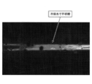
- FIG. 2 is a diagram illustrating an example of an image of a butt-welded portion captured by the imaging unit illustrated in FIG. 1.
- FIG. 3 is a diagram illustrating an example of an image of a butt-welded part taken without removing the imaging unit shown in FIG. 1 from the nozzle and re-installing the imaging conditions while maintaining the same imaging conditions, and without applying shielding gas or purge gas. is there.
- FIG. 4 is a schematic diagram showing a configuration of a modified example of the production status monitoring device for an ERW weld pipe according to an embodiment of the present invention.
- FIG. 1 is a schematic diagram showing the configuration of an electric resistance welded pipe manufacturing status monitoring apparatus according to an embodiment of the present invention.
- the manufacturing status monitoring apparatus 1 for an electric resistance welded pipe which is an embodiment of the present invention, forms a steel strip into a cylindrical shape and butts both ends in the width direction of the steel strip along the longitudinal direction.
- It is a device for monitoring the butt welding state of an electric resistance welded pipe (hereinafter abbreviated as an electric resistance steel pipe) P manufactured by welding, and includes a nozzle 2, an imaging unit 3, and an analysis unit 4 as main components. ing.
- the nozzle 2, the imaging unit 3, and the analysis unit 4 function as a gas shield nozzle, an imaging unit, and an analysis unit according to the present invention, respectively.
- the nozzle 2 has an opening 2a disposed opposite to a two-dimensional region of the electric resistance welded steel pipe P including a butt weld, and ejects a shielding gas (inert gas) from the opening 2a toward the two-dimensional region.
- a shielding gas inert gas
- the dimension of the opening 2a in the longitudinal direction of the steel strip is designed to be approximately 30 mm before and after the butt weld or larger than the size of the longitudinal field of view of the imaging unit 3.
- the dimension of the opening 2a in the width direction of the steel strip is designed to be about 10 mm or a size that does not interfere with the pair of squeeze top rolls R disposed above the ERW steel pipe P.
- the suitable butt angle of the steel strip changes according to the welding power related to the plate thickness of the steel strip and the transport speed of the steel strip, and as a result, the butt welding position on the transport line varies in the longitudinal direction of the steel strip.
- the size of the opening 2a in the longitudinal direction of the steel strip is made to take into account the variation width of the butt welding position, or the variation of the butt welding position can be covered by making the nozzle 2 movable in the longitudinal direction. It is desirable to do so.
- the shield gas may be supplied to the nozzle 2 using a gas supply source and a piping path (not shown).
- the gas supply source and the piping path may be configured using cylinders, tanks, and piping materials that are commercially available according to the type of shielding gas, and a mechanism for adjusting the pressure and flow rate of the shielding gas as necessary. May be provided.
- the imaging unit 3 is configured by an imaging device fixed inside the nozzle 2 by a fixing member 2 b provided on the inner wall surface of the nozzle 2.
- the imaging unit 3 captures an image of the butt weld of the ERW steel pipe P and outputs data of the captured image to the analysis unit 4.
- the field of view F of the imaging unit 3 preferably includes a range of 20 mm upstream in the transport direction of the butt weld. Further, it is desirable that the field of view of the imaging unit 3 on the downstream side in the transport direction includes the weld bead forming unit.
- FIG. 2 is a diagram illustrating an example of an image of the butt welded portion photographed by the imaging unit 3.
- FIG. 3 shows the butt welding in which the imaging unit 3 is detached from the nozzle 2 and installed without applying shield gas or purge gas while keeping the same imaging conditions (imaging distance, exposure time, lens aperture). It is a figure which shows an example of the image of a part.
- an image of the butt weld can be clearly captured. Yes.
- the image pickup unit 3 is removed from the nozzle 2 and installed without taking shield gas or purge gas, the cooling water of the squeeze top roll R stays in the butt weld and a clear image is obtained.
- the imaging unit 3 in the production status monitoring device for an electric resistance welded pipe which is an embodiment of the present invention, even if welding with a gas shield is used, the electric power is not affected by cooling water or lubricating water. It was confirmed that the image of the butt welded portion of the sewn steel pipe P was clearly taken and the quality of the butt welded portion could be determined based on the taken image.
- the exposure time of the imaging unit 3 is 1/100000 seconds or less, and the imaging unit 3 has a lens aperture and imaging sensitivity that do not saturate with this exposure time.
- the imaging unit 3 is configured as small as possible so that the tube cross-sectional area of the nozzle 2 having the imaging unit 3 therein is as small as possible.
- the analysis unit 4 is configured by an information processing device such as a personal computer.
- the analysis unit 4 uses the well-known edge extraction process and straight line approximation means, and the end portion in the width direction of the steel strip on the upstream side and the downstream side in the transport direction of the butt weld portion from the image of the butt weld portion taken by the imaging unit 3
- the position is extracted, and the geometric feature amount of the butt weld is calculated based on the extracted end position in the width direction.
- the analysis part 4 determines the quality of a butt-weld part based on the calculated geometric feature quantity, and outputs a determination result to the display means and warning means which are not shown in figure. Thereby, the operator can suppress the occurrence of poor welding by adjusting the manufacturing conditions of the ERW steel pipe based on the determination result.
- FIG. 4 is a schematic diagram showing a configuration of a modification of the production status monitoring device for an ERW weld pipe according to an embodiment of the present invention.
- the auxiliary nozzle 5 is arrange
- the range of the steel strip to which the inert gas is blown from the auxiliary nozzle 5 and the visual field range of the nozzle 2 are such that the temperature of the edge or end surface of the steel strip is raised by the induction heating device 6 and the oxygen concentration is 20.1%.
- a method for monitoring the production status of an electric resistance welded pipe and an electric power supply capable of determining the quality of a butt weld of an electric resistance welded pipe without being affected by cooling water or lubricating water even in the case of gas shield combined welding.
- a manufacturing status monitoring device for a sewn welded pipe can be provided.
Landscapes
- Engineering & Computer Science (AREA)
- Mechanical Engineering (AREA)
- Quality & Reliability (AREA)
Abstract
Description
本発明は、電縫溶接管の製造状況監視方法、電縫溶接管の製造状況監視装置、及び電縫溶接管の製造方法に関する。 The present invention relates to a manufacturing status monitoring method for an ERW welded pipe, a manufacturing status monitoring device for an ERW welded pipe, and a manufacturing method for an ERW welded pipe.
一般に、電縫溶接管(以下、電縫鋼管と略記)は、鋼帯等の金属帯(金属板を含む)を管状に成型しながら長手方向に搬送し、高周波誘導加熱圧接や抵抗加熱圧接等の手段を利用して金属帯の幅方向両端部を長手方向に沿って連続的に突き合わせ溶接することによって製造される。電縫鋼管の製造工程では、突き合わせ溶接部に酸化物等の異物を残存させないようにすることが突き合わせ溶接部の強度といった品質管理上重要である。このため、電縫鋼管の品質管理については、非特許文献1に開示されているような、超音波検査装置を利用して突き合わせ溶接部を中心に電縫鋼管内部の探傷を行う技術が普及している。
In general, ERW welded pipe (hereinafter abbreviated as ERW steel pipe) is transported in the longitudinal direction while forming a metal strip (including metal plate) such as a steel strip into a tubular shape, and is subjected to high-frequency induction heating pressure welding or resistance heating pressure welding. By using this means, both end portions in the width direction of the metal strip are continuously butt welded along the longitudinal direction. In the manufacturing process of the ERW steel pipe, it is important for quality control, such as the strength of the butt weld, to prevent foreign matters such as oxides from remaining in the butt weld. For this reason, regarding quality control of ERW steel pipes, a technique for flaw detection inside ERW steel pipes centering on a butt weld using an ultrasonic inspection device as disclosed in Non-Patent
一方、電縫鋼管の製造時の品質管理については、特許文献1に開示されているような、光切断法を利用して溶接ビード部の形状を測定し、測定結果から溶接ビード部の特徴量を算出して品質管理に用いる技術が提案されている。この技術では、断面のメタルフローとの間に相関関係を有する特徴量がオンラインで算出されるため、溶接工程を一旦中断して溶接突き合わせ部を採取して断面観察を行う工程を省略できる。また、品質管理に関する別の技術としては、特許文献2に開示されているような、撮像装置によって撮影された溶接突き合わせ部の画像から平面形状の特徴量を算出し、平面形状の特徴量が管理範囲内にあるか否かを判定する技術がある。
On the other hand, for quality control at the time of manufacturing the electric resistance welded steel pipe, the shape of the weld bead part is measured by using an optical cutting method as disclosed in
しかしながら、非特許文献1記載の技術は、電縫鋼管の品質保証には有効であるが、探傷結果と製造条件とが一意に結びつかないために探傷結果を製造条件に反映させることが難しい。また、超音波検査装置が最終検査工程に設置されている場合には、製造から検査までのリードタイムが大きいために溶接不良が発見された場合に製品のロスが大きい。また、特許文献1記載の技術では、溶接電力(入熱)や突き合わせ溶接部の段差等は的確に判別できるが、介在物排出により密接に関係する突き合わせ状態と製造条件との相関は得られにくい。一方、特許文献2記載の技術は、突き合わせ溶接部の平面形状を検出するので上記のような問題は発生しない。
However, although the technique described in Non-Patent
ところが、一般に、ラインパイプや自動車足回り材等の高級品向けの電縫鋼管の製造ラインには、一対のスクイズサイドロールに加えて、一対のスクイズトップロールが電縫鋼管の上方に設けられている。このため、特許文献2記載の技術を高級品向けの電縫鋼管の製造ラインに適用した場合、突き合わせ溶接部がスクイズトップロールの間に位置することによってスクイズトップロールの冷却や潤滑のために用いられる水が突き合わせ溶接部に滞留し、電縫鋼管の上方から突き合わせ溶接部の明瞭な画像が得られにくくなるために、突き合わせ溶接部の良否判定が困難になる。さらに、近年、抵抗溶接でも用いられ始めたガスシールド併用溶接においては、不活性ガスを噴出するノズルが突き合わせ溶接部の直上に配置されるために、特許文献2記載の技術によれば、電縫鋼管の上方に配置される撮像装置の視野を確保することができなくなり、突き合わせ溶接部の良否判定が困難になる。
However, in general, in a production line for high-grade products such as line pipes and automobile undercarriage materials, in addition to a pair of squeeze side rolls, a pair of squeeze top rolls is provided above the ERW steel pipe. Yes. For this reason, when the technology described in
他方、特許文献3記載の発明に倣って、電縫鋼管の加熱開始位置から溶接点に至る部分全体をシールドボックスで覆い、シールドボックス内に所定流量のガスを供給するシールド溶接装置を導入し、このシールド溶接装置に観察装置を設ける方法を用いることが考えられる。しかしながら、このような方法によれば、装置構造が大規模、且つ、複雑となり、鋼管の製造サイズを変更する度毎に鋼管の供給・排出部のシールド治具を交換、調整する必要が生じる等、能率面でのデメリットが大きい。
On the other hand, following the invention described in
本発明は、上記に鑑みてなされたものであって、ガスシールド併用溶接であっても冷却水や潤滑水の影響を受けることなく電縫溶接管の突き合わせ溶接部の良否を判定可能な電縫溶接管の製造状況監視方法及び電縫溶接管の製造状況監視装置を提供することを目的とする。 The present invention has been made in view of the above, and is capable of determining the quality of a butt-welded portion of an electric resistance welded pipe without being affected by cooling water or lubricating water even in the case of gas shield combined welding. It is an object of the present invention to provide a manufacturing status monitoring method for welded pipes and a manufacturing status monitoring device for ERW welded pipes.
また、本発明の他の目的は、ガスシールド併用溶接であっても冷却水や潤滑水の影響を受けることなく電縫溶接管の突き合わせ溶接部の良否を判定し、判定結果に基づいて溶接不良が発生することを抑制可能な電縫溶接管の製造方法を提供することを目的とする。 Another object of the present invention is to determine the quality of the butt welded portion of the ERW weld pipe without being affected by cooling water or lubricating water even in the case of gas shield combined welding, and weld failure based on the determination result An object of the present invention is to provide a method for manufacturing an electric resistance welded pipe capable of suppressing the occurrence of the above.
本発明に係る電縫溶接管の製造状況監視方法は、帯状の鋼帯を円筒状に成形し、該鋼帯の幅方向両端部を長手方向に沿って突き合わせ溶接することによって製造される電縫溶接管の製造状況を監視する電縫溶接管の製造状況監視方法であって、鋼帯の幅方向両端部が突き合わせ溶接される領域に対向する開口部を有し、前記開口部から前記領域に不活性ガスを噴出することによって前記領域を前記不活性ガスでシールドするガスシールドノズルの内部に、前記領域を視野に含む撮像手段を配置し、前記撮像手段によって撮影された画像に基づいて突き合わせ溶接部の良否を判定するステップを含むことを特徴とする。 The method for monitoring the production status of an electric resistance welded pipe according to the present invention is a method for producing an electric sewing machine by forming a strip-shaped steel strip into a cylindrical shape and butt-welding both ends in the width direction of the steel strip along the longitudinal direction. A method for monitoring the production status of an electric resistance welded pipe for monitoring the production status of a welded pipe, comprising an opening facing a region where both end portions in the width direction of the steel strip are butt welded, and from the opening to the region An image pickup means including the area in the field of view is disposed inside a gas shield nozzle that shields the area with the inert gas by ejecting an inert gas, and butt welding is performed based on an image taken by the image pickup means. The method includes a step of determining pass / fail of the part.
本発明に係る電縫溶接管の製造状況監視方法は、上記発明において、前記ガスシールドノズルの開口部は、前記鋼帯が溶融を開始する位置と鋼帯の長さ方向両端部が突き合わされる位置との間に位置し、鋼帯の誘導加熱開始点の間の所定の区間において、前記ガスシールドノズルとは別のノズルから鋼帯の幅方向両端部に不活性ガスを吹き付けることを特徴とする。 In the manufacturing method monitoring method for an electric resistance welded pipe according to the present invention, in the above invention, the opening of the gas shield nozzle abuts the position where the steel strip starts to melt and both ends in the length direction of the steel strip. And in a predetermined section between the induction heating start points of the steel strip, an inert gas is blown to both ends in the width direction of the steel strip from a nozzle different from the gas shield nozzle. To do.
本発明に係る電縫溶接管の製造状況監視装置は、帯状の鋼帯を円筒状に成形し、該鋼帯の幅方向両端部を長手方向に沿って突き合わせ溶接することによって製造される電縫溶接管の製造状況を監視する電縫溶接管の製造状況監視装置であって、鋼帯の幅方向両端部が突き合わせ溶接される領域に対向する開口部を有し、前記開口部から前記領域に不活性ガスを噴出することによって前記領域を前記不活性ガスでシールドするガスシールドノズルの内部に配置された、前記領域を視野に含む撮像手段と、前記撮像手段によって撮影された画像に基づいて突き合わせ溶接部の良否を判定する解析手段と、を備えることを特徴とする。 An apparatus for monitoring the production status of an electro-welded pipe according to the present invention is an electro-sewing manufactured by forming a strip-shaped steel strip into a cylindrical shape and butt-welding both ends of the steel strip in the longitudinal direction. An apparatus for monitoring the production status of an electric resistance welded pipe for monitoring the production status of a welded pipe, having an opening facing a region where both ends in the width direction of the steel strip are butt welded, and from the opening to the region Based on the image taken by the imaging means, the imaging means disposed in the gas shield nozzle that shields the area with the inert gas by ejecting the inert gas and including the area in the field of view Analyzing means for determining whether the welded portion is good or bad.
本発明に係る電縫溶接管の製造方法は、帯状の鋼帯を円筒状に成形し、該鋼帯の幅方向両端部を長手方向に沿って突き合わせ溶接することによって製造される電縫溶接管の製造方法であって、鋼帯の幅方向両端部が突き合わせ溶接される領域に対向する開口部を有し、前記開口部から前記領域に不活性ガスを噴出することによって前記領域を前記不活性ガスでシールドするガスシールドノズルの内部に、前記領域を視野に含む撮像手段を配置し、前記撮像手段によって撮影された画像に基づいて突き合わせ溶接部の良否を判定する判定ステップと、前記判定ステップの結果に基づいて前記電縫溶接管を製造するステップと、を含むことを特徴とする。 The method for producing an electric resistance welded pipe according to the present invention is an electric resistance welded pipe manufactured by forming a strip-shaped steel strip into a cylindrical shape and butt-welding both end portions in the width direction of the steel strip along the longitudinal direction. The steel strip has an opening facing a region where both ends in the width direction of the steel strip are butt welded, and the region is made inert by ejecting an inert gas from the opening to the region. A determination step of disposing an imaging unit including the region in the field of view inside a gas shield nozzle that shields with gas, and determining the quality of the butt weld based on an image captured by the imaging unit; and And manufacturing the electric resistance welded pipe based on the result.
本発明に係る電縫溶接管の製造状況監視方法及び電縫溶接管の製造状況監視装置によれば、ガスシールド併用溶接であっても冷却水や潤滑水の影響を受けることなく電縫溶接管の突き合わせ溶接部の良否を判定することができる。 According to the method for monitoring the production status of an electric resistance welded pipe and the device for monitoring the production status of an electric resistance welded pipe according to the present invention, the electric resistance welded pipe is not affected by cooling water or lubricating water even when welding with a gas shield is used. The quality of the butt welds can be determined.
本発明に係る電縫溶接管の製造方法によれば、ガスシールド併用溶接であっても冷却水や潤滑水の影響を受けることなく電縫溶接管の突き合わせ溶接部の良否を判定し、判別結果に基づいて溶接不良が発生することを抑制できる。 According to the method for manufacturing an electric resistance welded pipe according to the present invention, the quality of the butt welded portion of the electric resistance welded pipe is determined without being affected by cooling water or lubricating water even in the case of gas shield combined welding, and the determination result It is possible to suppress the occurrence of poor welding based on the above.
以下、図面を参照して、本発明の一実施形態である電縫溶接管の製造状況監視装置について詳細に説明する。 Hereinafter, with reference to the drawings, a manufacturing status monitoring device for an electric resistance welded pipe according to an embodiment of the present invention will be described in detail.
図1は、本発明の一実施形態である電縫溶接管の製造状況監視装置の構成を示す模式図である。図1に示すように、本発明の一実施形態である電縫溶接管の製造状況監視装置1は、鋼帯を円筒状に成形し、鋼帯の幅方向両端部を長手方向に沿って突き合わせ溶接することによって製造される電縫溶接管(以下、電縫鋼管と略記)Pの突き合わせ溶接状態を監視する装置であり、ノズル2、撮像部3、及び解析部4を主な構成要素として備えている。ノズル2、撮像部3、及び解析部4はそれぞれ、本発明に係るガスシールドノズル、撮像手段、及び解析手段として機能する。
FIG. 1 is a schematic diagram showing the configuration of an electric resistance welded pipe manufacturing status monitoring apparatus according to an embodiment of the present invention. As shown in FIG. 1, the manufacturing
ノズル2は、突き合わせ溶接部を含む電縫鋼管Pの2次元領域に対向配置された開口部2aを有し、開口部2aから2次元領域に向けてシールドガス(不活性ガス)を噴出することによって2次元領域をシールドガスでシールドするホーン状のノズルによって構成されている。
The
鋼帯の長手方向における開口部2aの寸法は、突き合わせ溶接部の前後30mm程度又は撮像部3の長手視野の大きさより大きく設計されている。一方、鋼帯の幅方向における開口部2aの寸法は、10mm程度又は電縫鋼管Pの上方に配置された一対のスクイズトップロールRに干渉しないだけの大きさに設計されている。
The dimension of the opening 2a in the longitudinal direction of the steel strip is designed to be approximately 30 mm before and after the butt weld or larger than the size of the longitudinal field of view of the
なお、鋼帯の板厚に関係する溶接電力や鋼帯の搬送速度に応じて鋼帯の好適な突き合わせ角が変化し、結果として搬送ライン上における突き合わせ溶接位置が鋼帯の長手方向に変動することがある。このため、鋼帯の長手方向における開口部2aの寸法を突き合わせ溶接位置の変動幅を考慮した大きさにするか、ノズル2を長手方向に移動可能にすることによって突き合わせ溶接位置の変動をカバーできるようにすることが望ましい。
The suitable butt angle of the steel strip changes according to the welding power related to the plate thickness of the steel strip and the transport speed of the steel strip, and as a result, the butt welding position on the transport line varies in the longitudinal direction of the steel strip. Sometimes. For this reason, the size of the opening 2a in the longitudinal direction of the steel strip is made to take into account the variation width of the butt welding position, or the variation of the butt welding position can be covered by making the
また、ノズル2へのシールドガスの供給は図示しないガス供給源及び配管経路を用いて行えばよい。また、ガス供給源及び配管経路はシールドガスの種別に応じて市販されているボンベ、タンク、及び配管材を用いて構成すればよく、また必要に応じてシールドガスの圧力や流量を調整する機構を設けてもよい。
Further, the shield gas may be supplied to the
撮像部3は、ノズル2の内壁面に設けられた固定部材2bによってノズル2の内部に固定された撮像装置によって構成されている。撮像部3は、電縫鋼管Pの突き合わせ溶接部の画像を撮影し、撮影された画像のデータを解析部4に出力する。撮像部3の視野Fは、好適には突き合わせ溶接部の搬送方向上流側20mmの範囲を含むことが望ましい。また、搬送方向下流側における撮像部3の視野は、溶接ビード形成部まで含むことが望ましい。
The
図2は、撮像部3によって撮影された突き合わせ溶接部の画像の一例を示す図である。一方、図3は、撮像条件(撮像距離や露光時間、レンズの絞り)を同一に保ったまま撮像部3をノズル2から取り外して設置し、シールドガスやパージガスも適用せずに撮影した突き合わせ溶接部の画像の一例を示す図である。
FIG. 2 is a diagram illustrating an example of an image of the butt welded portion photographed by the
図2及び図3との比較から明らかなように、本発明の一実施形態である電縫溶接管の製造状況監視装置における撮像部3によれば、突き合わせ溶接部の画像が明瞭に撮影できている。これに対して、撮像部3をノズル2から取り外して設置し、シールドガスやパージガスも適用せずに撮影した場合には、スクイズトップロールRの冷却水が突き合わせ溶接部に滞留して明瞭な画像が撮影できなかった。以上のことから、本発明の一実施形態である電縫溶接管の製造状況監視装置における撮像部3によれば、ガスシールド併用溶接であっても冷却水や潤滑水の影響を受けることなく電縫鋼管Pの突き合わせ溶接部の画像を明瞭に撮影し、撮影された画像に基づいて突き合わせ溶接部の良否を判定できることが確認された。
As is clear from comparison with FIG. 2 and FIG. 3, according to the
なお、解析部4の画像処理能力の関係上、撮像部3の露光時間は1/100000秒以下とし、撮像部3はこの露光時間でサチュレートしないレンズ絞り及び撮像感度を有することが望ましい。また、撮像部3は極力小型に構成し、撮像部3を内部に有するノズル2の管断面積がなるべく小型になるようにすることが望ましい。例えば現時点で市販されている電子露光機能付きの撮像装置で断面積が22mm×22mmであるものがあるのでそれを用いればよい。
Note that, due to the image processing capability of the
解析部4は、パーソナルコンピュータ等の情報処理装置によって構成されている。解析部4は、公知のエッジ抽出処理や直線近似手段を利用して撮像部3によって撮影された突き合わせ溶接部の画像から突き合わせ溶接部の搬送方向上流側及び下流側の鋼帯の幅方向端部位置を抽出し、抽出された幅方向端部位置に基づいて突き合わせ溶接部の幾何的特徴量を算出する。そして、解析部4は、算出された幾何的特徴量に基づいて突き合わせ溶接部の良否を判定し、図示しない表示手段や警報手段に判定結果を出力する。これにより、オペレータは、判定結果に基づいて電縫鋼管の製造条件を調整することによって溶接不良が発生することを抑制できる。
The
図4は、本発明の一実施形態である電縫溶接管の製造状況監視装置の変形例の構成を示す模式図である。図4に示すように、本変形例では、ノズル2の搬送方向上流側に補助ノズル5が配置され、この補助ノズル5から鋼帯のエッジ部に不活性ガスが吹き付けられる。ここで、補助ノズル5から不活性ガスを吹き付ける鋼帯の範囲やノズル2の視野範囲は、鋼帯のエッジ部又は端面の温度が誘導加熱装置6によって昇温し、酸素濃度20.1%で酸化を開始する温度に達する位置より搬送方向下流側とすればよく、ノズル2の視野範囲としては鋼帯のエッジ部が溶融を開始する位置を含む範囲とした。これにより、ガスシールドノズルの効果を保ちつつ、ノズル2の開口部の長手方向の大きさを必要最小源に抑えることができる。なお、本変形例の動作は図1に示す装置と同じであるので、その説明は省略する。
FIG. 4 is a schematic diagram showing a configuration of a modification of the production status monitoring device for an ERW weld pipe according to an embodiment of the present invention. As shown in FIG. 4, in this modification, the
以上、本発明者によってなされた発明を適用した実施の形態について説明したが、本実施形態による本発明の開示の一部をなす記述及び図面により本発明は限定されることはなく、上述した各構成要素を適宜組み合わせて構成したものも本発明に含まれる。すなわち、本実施形態に基づいて当業者等によりなされる他の実施の形態、実施例及び運用技術等は全て本発明の範疇に含まれる。 As mentioned above, although the embodiment to which the invention made by the present inventor is applied has been described, the present invention is not limited by the description and the drawings constituting a part of the disclosure of the present invention according to the present embodiment. What was comprised combining the component suitably is also contained in this invention. That is, other embodiments, examples, operational techniques, and the like made by those skilled in the art based on the present embodiment are all included in the scope of the present invention.
本発明によれば、ガスシールド併用溶接であっても冷却水や潤滑水の影響を受けることなく電縫溶接管の突き合わせ溶接部の良否を判定可能な電縫溶接管の製造状況監視方法及び電縫溶接管の製造状況監視装置を提供することができる。 According to the present invention, there is provided a method for monitoring the production status of an electric resistance welded pipe and an electric power supply capable of determining the quality of a butt weld of an electric resistance welded pipe without being affected by cooling water or lubricating water even in the case of gas shield combined welding. A manufacturing status monitoring device for a sewn welded pipe can be provided.
1 電縫溶接管の製造状況監視装置
2 ノズル
2a 開口部
3 撮像部
4 解析部
5 補助ノズル
6 誘導加熱装置
P 電縫溶接管(電縫鋼管)
DESCRIPTION OF
Claims (4)
鋼帯の幅方向両端部が突き合わせ溶接される領域に対向する開口部を有し、前記開口部から前記領域に不活性ガスを噴出することによって前記領域を前記不活性ガスでシールドするガスシールドノズルの内部に、前記領域を視野に含む撮像手段を配置し、前記撮像手段によって撮影された画像に基づいて突き合わせ溶接部の良否を判定するステップを含むことを特徴とする電縫溶接管の製造状況監視方法。 Manufacturing status of ERW welded pipe that monitors the manufacturing status of ERW welded pipe manufactured by forming a strip-shaped steel strip into a cylindrical shape and butt-welding both ends of the steel strip in the longitudinal direction A monitoring method,
A gas shield nozzle having an opening facing a region where both ends in the width direction of the steel strip are butt welded, and shielding the region with the inert gas by ejecting an inert gas from the opening to the region An image-pickup means including the region in the field of view, and determining the quality of the butt weld based on the image taken by the image-pickup means. Monitoring method.
鋼帯の幅方向両端部が突き合わせ溶接される領域に対向する開口部を有し、前記開口部から前記領域に不活性ガスを噴出することによって前記領域を前記不活性ガスでシールドするガスシールドノズルの内部に配置された、前記領域を視野に含む撮像手段と、
前記撮像手段によって撮影された画像に基づいて突き合わせ溶接部の良否を判定する解析手段と、
を備えることを特徴とする電縫溶接管の製造状況監視装置。 Manufacturing status of ERW welded pipe that monitors the manufacturing status of ERW welded pipe manufactured by forming a strip-shaped steel strip into a cylindrical shape and butt-welding both ends of the steel strip in the longitudinal direction A monitoring device,
A gas shield nozzle having an opening facing a region where both ends in the width direction of the steel strip are butt welded, and shielding the region with the inert gas by ejecting an inert gas from the opening to the region An imaging means arranged inside the field of view and including the region in the field of view;
Analysis means for determining the quality of the butt weld based on the image photographed by the imaging means;
A production status monitoring device for an electric resistance welded pipe, comprising:
鋼帯の幅方向両端部が突き合わせ溶接される領域に対向する開口部を有し、前記開口部から前記領域に不活性ガスを噴出することによって前記領域を前記不活性ガスでシールドするガスシールドノズルの内部に、前記領域を視野に含む撮像手段を配置し、前記撮像手段によって撮影された画像に基づいて突き合わせ溶接部の良否を判定する判定ステップと、
前記判定ステップの結果に基づいて前記電縫溶接管を製造するステップと、
を含むことを特徴とする電縫溶接管の製造方法。 A method of manufacturing an electric resistance welded pipe manufactured by forming a strip-shaped steel strip into a cylindrical shape and butt-welding both ends in the width direction of the steel strip along the longitudinal direction,
A gas shield nozzle having an opening facing a region where both ends in the width direction of the steel strip are butt welded, and shielding the region with the inert gas by ejecting an inert gas from the opening to the region A determination step of disposing an imaging means including the region in the field of view, and determining the quality of the butt weld based on an image taken by the imaging means;
Manufacturing the electric resistance welded pipe based on the result of the determining step;
A method for producing an electric resistance welded pipe, comprising:
Priority Applications (6)
| Application Number | Priority Date | Filing Date | Title |
|---|---|---|---|
| JP2016544485A JP6015883B1 (en) | 2015-03-10 | 2016-02-17 | Manufacturing method monitoring method for ERW welded pipe, manufacturing status monitoring device for ERW welded pipe, and method for manufacturing ERW welded pipe |
| KR1020177026085A KR20170118810A (en) | 2015-03-10 | 2016-02-17 | Method of monitoring manufacturing status of electric resistance welded pipe, device for monitoring manufacturing status of electric resistance welded pipe, and method of manufacturing electric resistance welded pipe |
| US15/555,039 US10744589B2 (en) | 2015-03-10 | 2016-02-17 | Method of monitoring manufacturing status of electric resistance welded pipe, device for monitoring manufacturing status of electric resistance welded pipe, and method of manufacturing electric resistance welded pipe |
| EP16761445.2A EP3269490B1 (en) | 2015-03-10 | 2016-02-17 | Method of monitoring manufacturing status of electric resistance welded pipe, device for monitoring manufacturing status of electric resistance welded pipe, and method of manufacturing electric resistance welded pipe |
| CN201680011286.0A CN107249806B (en) | 2015-03-10 | 2016-02-17 | Method and device for monitoring manufacturing condition of electric resistance welded steel pipe and method for manufacturing the same |
| RU2017134921A RU2682511C1 (en) | 2015-03-10 | 2016-02-17 | Method and device for control over manufacturing mode of pipe manufactured by electric welding by resistance method, and manufacturing method of such pipe |
Applications Claiming Priority (2)
| Application Number | Priority Date | Filing Date | Title |
|---|---|---|---|
| JP2015-047625 | 2015-03-10 | ||
| JP2015047625 | 2015-03-10 |
Publications (1)
| Publication Number | Publication Date |
|---|---|
| WO2016143473A1 true WO2016143473A1 (en) | 2016-09-15 |
Family
ID=56879358
Family Applications (1)
| Application Number | Title | Priority Date | Filing Date |
|---|---|---|---|
| PCT/JP2016/054533 Ceased WO2016143473A1 (en) | 2015-03-10 | 2016-02-17 | Method of monitoring manufacturing status of electric resistance welded pipe, device for monitoring manufacturing status of electric resistance welded pipe, and method of manufacturing electric resistance welded pipe |
Country Status (7)
| Country | Link |
|---|---|
| US (1) | US10744589B2 (en) |
| EP (1) | EP3269490B1 (en) |
| JP (1) | JP6015883B1 (en) |
| KR (1) | KR20170118810A (en) |
| CN (1) | CN107249806B (en) |
| RU (1) | RU2682511C1 (en) |
| WO (1) | WO2016143473A1 (en) |
Families Citing this family (3)
| Publication number | Priority date | Publication date | Assignee | Title |
|---|---|---|---|---|
| EP3542917B1 (en) * | 2016-11-15 | 2023-03-08 | Nippon Steel Corporation | Apparatus,method, and program for monitoring operation of high-frequency resistance welding and induction heating welding of electric resistance welded steel pipe |
| KR20200064128A (en) * | 2018-01-22 | 2020-06-05 | 닛폰세이테츠 가부시키가이샤 | Electrode steel pipe manufacturing apparatus and electrorepeated steel pipe manufacturing method |
| US11828190B2 (en) | 2021-11-18 | 2023-11-28 | General Electric Company | Airfoil joining apparatus and methods |
Citations (2)
| Publication number | Priority date | Publication date | Assignee | Title |
|---|---|---|---|---|
| WO2009057830A1 (en) * | 2007-11-02 | 2009-05-07 | Nippon Steel Corporation | Welded state monitoring device and method |
| JP2014231084A (en) * | 2013-05-30 | 2014-12-11 | Jfeスチール株式会社 | Weld shield system for electroseamed steel pipe |
Family Cites Families (17)
| Publication number | Priority date | Publication date | Assignee | Title |
|---|---|---|---|---|
| US3585351A (en) * | 1969-08-25 | 1971-06-15 | Smith Corp A O | Electron beam welding process and apparatus |
| US5223683A (en) * | 1991-07-23 | 1993-06-29 | Kabushiki Kaisha Meidensha | High frequency electronic welding system |
| US5344062A (en) | 1993-06-24 | 1994-09-06 | The Idod Trust | Method of forming seamed metal tube |
| US5376766A (en) * | 1993-07-08 | 1994-12-27 | Valmont Industries, Inc. | Weld quality monitoring and control system for a tube mill |
| JPH08300172A (en) | 1995-04-28 | 1996-11-19 | Nkk Corp | Manufacturing method of welded steel pipe |
| JP4374845B2 (en) | 2002-11-29 | 2009-12-02 | Jfeスチール株式会社 | Method and apparatus for detecting bead shape of ERW pipe |
| JP4028861B2 (en) | 2004-07-16 | 2007-12-26 | 新日本製鐵株式会社 | Manufacturing method of ERW steel pipe with excellent weld quality |
| JP4777856B2 (en) * | 2006-10-02 | 2011-09-21 | 東急車輛製造株式会社 | Laser welding equipment |
| CN101610869B (en) * | 2007-02-13 | 2011-11-30 | 杰富意钢铁株式会社 | Seam-welded steel pipe manufacturing method and its manufacturing apparatus |
| JP5014837B2 (en) * | 2007-03-01 | 2012-08-29 | 新日本製鐵株式会社 | ERW steel pipe manufacturing method |
| TW200900173A (en) | 2007-03-02 | 2009-01-01 | Nippon Steel Corp | Method for producing steel conduit tube and high Si component or high Cr component steel conduit tube |
| WO2009128231A1 (en) | 2008-04-14 | 2009-10-22 | 株式会社 東芝 | Laser welding device and laser welding method |
| JP5739619B2 (en) | 2010-03-30 | 2015-06-24 | 日新製鋼株式会社 | ERW steel pipe seal box welding equipment |
| EP2777859B1 (en) * | 2011-11-09 | 2016-09-28 | Nippon Steel & Sumitomo Metal Corporation | Monitoring device, method, and program for seam welding, and storage medium |
| KR101484902B1 (en) | 2012-04-18 | 2015-01-20 | 신닛테츠스미킨 카부시키카이샤 | Electric resistance welding operation management device, electric resistance welding operation management method, and computer readable recording medium recording computer program |
| JP2014184469A (en) * | 2013-03-25 | 2014-10-02 | Jfe Steel Corp | Shield device for zone-to-be-welded of tube stock of electric resistance welded steel pipe |
| CN103240515B (en) * | 2013-05-24 | 2015-03-25 | 西安石油大学 | Quality control method for high-frequency resistance welded pipe welding area |
-
2016
- 2016-02-17 RU RU2017134921A patent/RU2682511C1/en active
- 2016-02-17 WO PCT/JP2016/054533 patent/WO2016143473A1/en not_active Ceased
- 2016-02-17 CN CN201680011286.0A patent/CN107249806B/en active Active
- 2016-02-17 JP JP2016544485A patent/JP6015883B1/en active Active
- 2016-02-17 US US15/555,039 patent/US10744589B2/en active Active
- 2016-02-17 KR KR1020177026085A patent/KR20170118810A/en not_active Ceased
- 2016-02-17 EP EP16761445.2A patent/EP3269490B1/en active Active
Patent Citations (2)
| Publication number | Priority date | Publication date | Assignee | Title |
|---|---|---|---|---|
| WO2009057830A1 (en) * | 2007-11-02 | 2009-05-07 | Nippon Steel Corporation | Welded state monitoring device and method |
| JP2014231084A (en) * | 2013-05-30 | 2014-12-11 | Jfeスチール株式会社 | Weld shield system for electroseamed steel pipe |
Non-Patent Citations (1)
| Title |
|---|
| See also references of EP3269490A4 * |
Also Published As
| Publication number | Publication date |
|---|---|
| EP3269490A4 (en) | 2018-11-14 |
| KR20170118810A (en) | 2017-10-25 |
| CN107249806B (en) | 2020-02-18 |
| US20180104763A1 (en) | 2018-04-19 |
| EP3269490A1 (en) | 2018-01-17 |
| EP3269490B1 (en) | 2024-08-21 |
| US10744589B2 (en) | 2020-08-18 |
| CN107249806A (en) | 2017-10-13 |
| RU2682511C1 (en) | 2019-03-19 |
| JP6015883B1 (en) | 2016-10-26 |
| JPWO2016143473A1 (en) | 2017-04-27 |
Similar Documents
| Publication | Publication Date | Title |
|---|---|---|
| JP5967042B2 (en) | Laser welding quality determination device and laser welding quality determination method | |
| JP5182330B2 (en) | Welding state monitoring device and method | |
| CN104245222B (en) | Method and apparatus for carrying out the longitudinal seam welding of profile material tube on pipe welding equipment | |
| JP6015883B1 (en) | Manufacturing method monitoring method for ERW welded pipe, manufacturing status monitoring device for ERW welded pipe, and method for manufacturing ERW welded pipe | |
| JP5332287B2 (en) | ERW welding system | |
| US20080237197A1 (en) | System and method for welding and real time monitoring of seam welded parts | |
| JP5125670B2 (en) | A method for manufacturing ERW welded pipes with excellent welding quality. | |
| JP5014837B2 (en) | ERW steel pipe manufacturing method | |
| JP5909872B2 (en) | WELDING DEFECT DETECTING METHOD AND SYSTEM, ELECTRIC SEWING TUBE MANUFACTURING METHOD, AND WELDED PRODUCT MANUFACTURING METHOD | |
| JP5909874B2 (en) | Welding defect detection system for ERW pipe and method for manufacturing ERW pipe | |
| JP4935703B2 (en) | Method for producing ERW steel pipe with good weld toughness | |
| JP5082746B2 (en) | Manufacturing equipment and manufacturing method of square steel pipe | |
| JP4532977B2 (en) | Welding method for ERW steel pipe with excellent welding quality | |
| JP6094690B2 (en) | Laser irradiation position deviation detection method for laser welded steel pipe, steel pipe manufacturing method, laser irradiation position deviation detection apparatus, steel pipe laser welding apparatus, and steel pipe manufacturing apparatus | |
| JP6142858B2 (en) | Method and apparatus for measuring shape of forged steel pipe | |
| JP7119561B2 (en) | MONITORING METHOD, MONITORING SYSTEM AND MONITORING PROGRAM FOR ERW WELDING | |
| JP5881942B2 (en) | Weld defect detection system, method for manufacturing ERW steel pipe, and method for manufacturing welded product | |
| JP4589898B2 (en) | Steel strip butt welder | |
| JP2000111328A (en) | Method for inspecting welding part of welding pipe | |
| JP2017056472A (en) | ERW welding process monitoring device and monitoring method | |
| JP3071595B2 (en) | Diagnosis method of surface layer inclusion detection device | |
| JP6054618B2 (en) | Welded steel pipe manufacturing equipment | |
| JP2004301611A (en) | Method and apparatus for detecting crack in thermally affected part of plated steel pipe | |
| JP2017087283A (en) | Welded state monitor and welded state monitoring method | |
| JP5797375B2 (en) | ERW steel pipe manufacturing method |
Legal Events
| Date | Code | Title | Description |
|---|---|---|---|
| ENP | Entry into the national phase |
Ref document number: 2016544485 Country of ref document: JP Kind code of ref document: A |
|
| 121 | Ep: the epo has been informed by wipo that ep was designated in this application |
Ref document number: 16761445 Country of ref document: EP Kind code of ref document: A1 |
|
| WWE | Wipo information: entry into national phase |
Ref document number: 15555039 Country of ref document: US |
|
| REEP | Request for entry into the european phase |
Ref document number: 2016761445 Country of ref document: EP |
|
| NENP | Non-entry into the national phase |
Ref country code: DE |
|
| ENP | Entry into the national phase |
Ref document number: 20177026085 Country of ref document: KR Kind code of ref document: A |
|
| WWE | Wipo information: entry into national phase |
Ref document number: 2017134921 Country of ref document: RU |