WO2016143473A1 - Procédé de surveillance d'état de fabrication de tuyau soudé par résistance électrique, dispositif de surveillance d'état de fabrication de tuyau soudé par résistance électrique, et procédé de fabrication de tuyau soudé par résistance électrique - Google Patents
Procédé de surveillance d'état de fabrication de tuyau soudé par résistance électrique, dispositif de surveillance d'état de fabrication de tuyau soudé par résistance électrique, et procédé de fabrication de tuyau soudé par résistance électrique Download PDFInfo
- Publication number
- WO2016143473A1 WO2016143473A1 PCT/JP2016/054533 JP2016054533W WO2016143473A1 WO 2016143473 A1 WO2016143473 A1 WO 2016143473A1 JP 2016054533 W JP2016054533 W JP 2016054533W WO 2016143473 A1 WO2016143473 A1 WO 2016143473A1
- Authority
- WO
- WIPO (PCT)
- Prior art keywords
- steel strip
- welded pipe
- region
- electric resistance
- butt
- Prior art date
- Legal status (The legal status is an assumption and is not a legal conclusion. Google has not performed a legal analysis and makes no representation as to the accuracy of the status listed.)
- Ceased
Links
Images


Classifications
-
- B—PERFORMING OPERATIONS; TRANSPORTING
- B23—MACHINE TOOLS; METAL-WORKING NOT OTHERWISE PROVIDED FOR
- B23K—SOLDERING OR UNSOLDERING; WELDING; CLADDING OR PLATING BY SOLDERING OR WELDING; CUTTING BY APPLYING HEAT LOCALLY, e.g. FLAME CUTTING; WORKING BY LASER BEAM
- B23K13/00—Welding by high-frequency current heating
- B23K13/08—Electric supply or control circuits therefor
-
- B—PERFORMING OPERATIONS; TRANSPORTING
- B23—MACHINE TOOLS; METAL-WORKING NOT OTHERWISE PROVIDED FOR
- B23K—SOLDERING OR UNSOLDERING; WELDING; CLADDING OR PLATING BY SOLDERING OR WELDING; CUTTING BY APPLYING HEAT LOCALLY, e.g. FLAME CUTTING; WORKING BY LASER BEAM
- B23K13/00—Welding by high-frequency current heating
-
- B—PERFORMING OPERATIONS; TRANSPORTING
- B23—MACHINE TOOLS; METAL-WORKING NOT OTHERWISE PROVIDED FOR
- B23K—SOLDERING OR UNSOLDERING; WELDING; CLADDING OR PLATING BY SOLDERING OR WELDING; CUTTING BY APPLYING HEAT LOCALLY, e.g. FLAME CUTTING; WORKING BY LASER BEAM
- B23K11/00—Resistance welding; Severing by resistance heating
- B23K11/0006—Resistance welding; Severing by resistance heating the welding zone being shielded against the influence of the surrounding atmosphere
-
- B—PERFORMING OPERATIONS; TRANSPORTING
- B21—MECHANICAL METAL-WORKING WITHOUT ESSENTIALLY REMOVING MATERIAL; PUNCHING METAL
- B21C—MANUFACTURE OF METAL SHEETS, WIRE, RODS, TUBES, PROFILES OR LIKE SEMI-MANUFACTURED PRODUCTS OTHERWISE THAN BY ROLLING; AUXILIARY OPERATIONS USED IN CONNECTION WITH METAL-WORKING WITHOUT ESSENTIALLY REMOVING MATERIAL
- B21C37/00—Manufacture of metal sheets, rods, wire, tubes, profiles or like semi-manufactured products, not otherwise provided for; Manufacture of tubes of special shape
- B21C37/06—Manufacture of metal sheets, rods, wire, tubes, profiles or like semi-manufactured products, not otherwise provided for; Manufacture of tubes of special shape of tubes or metal hoses; Combined procedures for making tubes, e.g. for making multi-wall tubes
- B21C37/08—Making tubes with welded or soldered seams
-
- B—PERFORMING OPERATIONS; TRANSPORTING
- B21—MECHANICAL METAL-WORKING WITHOUT ESSENTIALLY REMOVING MATERIAL; PUNCHING METAL
- B21C—MANUFACTURE OF METAL SHEETS, WIRE, RODS, TUBES, PROFILES OR LIKE SEMI-MANUFACTURED PRODUCTS OTHERWISE THAN BY ROLLING; AUXILIARY OPERATIONS USED IN CONNECTION WITH METAL-WORKING WITHOUT ESSENTIALLY REMOVING MATERIAL
- B21C51/00—Measuring, gauging, indicating, counting, or marking devices specially adapted for use in the production or manipulation of material in accordance with subclasses B21B - B21F
-
- B—PERFORMING OPERATIONS; TRANSPORTING
- B23—MACHINE TOOLS; METAL-WORKING NOT OTHERWISE PROVIDED FOR
- B23K—SOLDERING OR UNSOLDERING; WELDING; CLADDING OR PLATING BY SOLDERING OR WELDING; CUTTING BY APPLYING HEAT LOCALLY, e.g. FLAME CUTTING; WORKING BY LASER BEAM
- B23K11/00—Resistance welding; Severing by resistance heating
- B23K11/06—Resistance welding; Severing by resistance heating using roller electrodes
- B23K11/061—Resistance welding; Severing by resistance heating using roller electrodes for welding rectilinear seams
- B23K11/062—Resistance welding; Severing by resistance heating using roller electrodes for welding rectilinear seams for welding longitudinal seams of tubes
-
- B—PERFORMING OPERATIONS; TRANSPORTING
- B23—MACHINE TOOLS; METAL-WORKING NOT OTHERWISE PROVIDED FOR
- B23K—SOLDERING OR UNSOLDERING; WELDING; CLADDING OR PLATING BY SOLDERING OR WELDING; CUTTING BY APPLYING HEAT LOCALLY, e.g. FLAME CUTTING; WORKING BY LASER BEAM
- B23K11/00—Resistance welding; Severing by resistance heating
- B23K11/08—Seam welding not restricted to one of the preceding subgroups
- B23K11/087—Seam welding not restricted to one of the preceding subgroups for rectilinear seams
- B23K11/0873—Seam welding not restricted to one of the preceding subgroups for rectilinear seams of the longitudinal seam of tubes
-
- B—PERFORMING OPERATIONS; TRANSPORTING
- B23—MACHINE TOOLS; METAL-WORKING NOT OTHERWISE PROVIDED FOR
- B23K—SOLDERING OR UNSOLDERING; WELDING; CLADDING OR PLATING BY SOLDERING OR WELDING; CUTTING BY APPLYING HEAT LOCALLY, e.g. FLAME CUTTING; WORKING BY LASER BEAM
- B23K11/00—Resistance welding; Severing by resistance heating
- B23K11/16—Resistance welding; Severing by resistance heating taking account of the properties of the material to be welded
-
- B—PERFORMING OPERATIONS; TRANSPORTING
- B23—MACHINE TOOLS; METAL-WORKING NOT OTHERWISE PROVIDED FOR
- B23K—SOLDERING OR UNSOLDERING; WELDING; CLADDING OR PLATING BY SOLDERING OR WELDING; CUTTING BY APPLYING HEAT LOCALLY, e.g. FLAME CUTTING; WORKING BY LASER BEAM
- B23K11/00—Resistance welding; Severing by resistance heating
- B23K11/24—Electric supply or control circuits therefor
- B23K11/25—Monitoring devices
- B23K11/252—Monitoring devices using digital means
-
- B—PERFORMING OPERATIONS; TRANSPORTING
- B23—MACHINE TOOLS; METAL-WORKING NOT OTHERWISE PROVIDED FOR
- B23K—SOLDERING OR UNSOLDERING; WELDING; CLADDING OR PLATING BY SOLDERING OR WELDING; CUTTING BY APPLYING HEAT LOCALLY, e.g. FLAME CUTTING; WORKING BY LASER BEAM
- B23K13/00—Welding by high-frequency current heating
- B23K13/01—Welding by high-frequency current heating by induction heating
- B23K13/02—Seam welding
- B23K13/025—Seam welding for tubes
-
- B—PERFORMING OPERATIONS; TRANSPORTING
- B23—MACHINE TOOLS; METAL-WORKING NOT OTHERWISE PROVIDED FOR
- B23K—SOLDERING OR UNSOLDERING; WELDING; CLADDING OR PLATING BY SOLDERING OR WELDING; CUTTING BY APPLYING HEAT LOCALLY, e.g. FLAME CUTTING; WORKING BY LASER BEAM
- B23K13/00—Welding by high-frequency current heating
- B23K13/06—Welding by high-frequency current heating characterised by the shielding of the welding zone against influence of the surrounding atmosphere
-
- B—PERFORMING OPERATIONS; TRANSPORTING
- B23—MACHINE TOOLS; METAL-WORKING NOT OTHERWISE PROVIDED FOR
- B23K—SOLDERING OR UNSOLDERING; WELDING; CLADDING OR PLATING BY SOLDERING OR WELDING; CUTTING BY APPLYING HEAT LOCALLY, e.g. FLAME CUTTING; WORKING BY LASER BEAM
- B23K31/00—Processes relevant to this subclass, specially adapted for particular articles or purposes, but not covered by any single one of main groups B23K1/00 - B23K28/00
- B23K31/12—Processes relevant to this subclass, specially adapted for particular articles or purposes, but not covered by any single one of main groups B23K1/00 - B23K28/00 relating to investigating the properties, e.g. the weldability, of materials
- B23K31/125—Weld quality monitoring
-
- B—PERFORMING OPERATIONS; TRANSPORTING
- B23—MACHINE TOOLS; METAL-WORKING NOT OTHERWISE PROVIDED FOR
- B23K—SOLDERING OR UNSOLDERING; WELDING; CLADDING OR PLATING BY SOLDERING OR WELDING; CUTTING BY APPLYING HEAT LOCALLY, e.g. FLAME CUTTING; WORKING BY LASER BEAM
- B23K2101/00—Articles made by soldering, welding or cutting
- B23K2101/04—Tubular or hollow articles
-
- B—PERFORMING OPERATIONS; TRANSPORTING
- B23—MACHINE TOOLS; METAL-WORKING NOT OTHERWISE PROVIDED FOR
- B23K—SOLDERING OR UNSOLDERING; WELDING; CLADDING OR PLATING BY SOLDERING OR WELDING; CUTTING BY APPLYING HEAT LOCALLY, e.g. FLAME CUTTING; WORKING BY LASER BEAM
- B23K2103/00—Materials to be soldered, welded or cut
- B23K2103/02—Iron or ferrous alloys
- B23K2103/04—Steel or steel alloys
Definitions
- the present invention relates to a manufacturing status monitoring method for an ERW welded pipe, a manufacturing status monitoring device for an ERW welded pipe, and a manufacturing method for an ERW welded pipe.
- ERW welded pipe (hereinafter abbreviated as ERW steel pipe) is transported in the longitudinal direction while forming a metal strip (including metal plate) such as a steel strip into a tubular shape, and is subjected to high-frequency induction heating pressure welding or resistance heating pressure welding.
- a metal strip including metal plate
- both end portions in the width direction of the metal strip are continuously butt welded along the longitudinal direction.
- quality control such as the strength of the butt weld
- a technique for flaw detection inside ERW steel pipes centering on a butt weld using an ultrasonic inspection device as disclosed in Non-Patent Document 1 has become widespread. ing.
- the shape of the weld bead part is measured by using an optical cutting method as disclosed in Patent Document 1, and the feature amount of the weld bead part is determined from the measurement result.
- Techniques for calculating and using for quality control have been proposed. In this technique, since the feature quantity having a correlation with the metal flow of the cross section is calculated online, it is possible to omit the step of suspending the welding process, collecting the weld butt portion, and observing the cross section.
- a planar shape feature amount is calculated from an image of a welding butt portion photographed by an imaging device as disclosed in Patent Document 2, and the planar shape feature amount is managed. There is a technique for determining whether or not the value is within a range.
- Non-Patent Document 1 is effective for quality assurance of an electric resistance welded steel pipe, it is difficult to reflect the flaw detection result in the manufacturing condition because the flaw detection result and the manufacturing condition are not uniquely linked.
- the ultrasonic inspection apparatus is installed in the final inspection process, the product loss is large when a welding defect is found because the lead time from manufacture to inspection is large.
- the welding power (heat input), the level difference of the butt weld, and the like can be accurately determined, but it is difficult to obtain a correlation between the butt state more closely related to the inclusion discharge and the manufacturing conditions. .
- Patent Document 2 since the technique described in Patent Document 2 detects the planar shape of the butt weld, the above-described problem does not occur.
- the nozzle for injecting the inert gas is disposed immediately above the butt weld.
- the field of view of the imaging device arranged above the steel pipe cannot be secured, and it is difficult to determine whether the butt weld is good or bad.
- the present invention has been made in view of the above, and is capable of determining the quality of a butt-welded portion of an electric resistance welded pipe without being affected by cooling water or lubricating water even in the case of gas shield combined welding. It is an object of the present invention to provide a manufacturing status monitoring method for welded pipes and a manufacturing status monitoring device for ERW welded pipes.
- Another object of the present invention is to determine the quality of the butt welded portion of the ERW weld pipe without being affected by cooling water or lubricating water even in the case of gas shield combined welding, and weld failure based on the determination result
- An object of the present invention is to provide a method for manufacturing an electric resistance welded pipe capable of suppressing the occurrence of the above.
- the method for monitoring the production status of an electric resistance welded pipe is a method for producing an electric sewing machine by forming a strip-shaped steel strip into a cylindrical shape and butt-welding both ends in the width direction of the steel strip along the longitudinal direction.
- a method for monitoring the production status of an electric resistance welded pipe for monitoring the production status of a welded pipe comprising an opening facing a region where both end portions in the width direction of the steel strip are butt welded, and from the opening to the region
- An image pickup means including the area in the field of view is disposed inside a gas shield nozzle that shields the area with the inert gas by ejecting an inert gas, and butt welding is performed based on an image taken by the image pickup means.
- the method includes a step of determining pass / fail of the part.
- the opening of the gas shield nozzle abuts the position where the steel strip starts to melt and both ends in the length direction of the steel strip. And in a predetermined section between the induction heating start points of the steel strip, an inert gas is blown to both ends in the width direction of the steel strip from a nozzle different from the gas shield nozzle. To do.
- An apparatus for monitoring the production status of an electro-welded pipe is an electro-sewing manufactured by forming a strip-shaped steel strip into a cylindrical shape and butt-welding both ends of the steel strip in the longitudinal direction.
- An apparatus for monitoring the production status of an electric resistance welded pipe for monitoring the production status of a welded pipe, having an opening facing a region where both ends in the width direction of the steel strip are butt welded, and from the opening to the region Based on the image taken by the imaging means, the imaging means disposed in the gas shield nozzle that shields the area with the inert gas by ejecting the inert gas and including the area in the field of view Analyzing means for determining whether the welded portion is good or bad.
- the method for producing an electric resistance welded pipe according to the present invention is an electric resistance welded pipe manufactured by forming a strip-shaped steel strip into a cylindrical shape and butt-welding both end portions in the width direction of the steel strip along the longitudinal direction.
- the steel strip has an opening facing a region where both ends in the width direction of the steel strip are butt welded, and the region is made inert by ejecting an inert gas from the opening to the region.
- the electric resistance welded pipe is not affected by cooling water or lubricating water even when welding with a gas shield is used.
- the quality of the butt welds can be determined.
- the quality of the butt welded portion of the electric resistance welded pipe is determined without being affected by cooling water or lubricating water even in the case of gas shield combined welding, and the determination result It is possible to suppress the occurrence of poor welding based on the above.
- FIG. 1 is a schematic diagram showing the configuration of an electro-welded pipe manufacturing status monitoring apparatus according to an embodiment of the present invention.
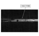
- FIG. 2 is a diagram illustrating an example of an image of a butt-welded portion captured by the imaging unit illustrated in FIG. 1.
- FIG. 3 is a diagram illustrating an example of an image of a butt-welded part taken without removing the imaging unit shown in FIG. 1 from the nozzle and re-installing the imaging conditions while maintaining the same imaging conditions, and without applying shielding gas or purge gas. is there.
- FIG. 4 is a schematic diagram showing a configuration of a modified example of the production status monitoring device for an ERW weld pipe according to an embodiment of the present invention.
- FIG. 1 is a schematic diagram showing the configuration of an electric resistance welded pipe manufacturing status monitoring apparatus according to an embodiment of the present invention.
- the manufacturing status monitoring apparatus 1 for an electric resistance welded pipe which is an embodiment of the present invention, forms a steel strip into a cylindrical shape and butts both ends in the width direction of the steel strip along the longitudinal direction.
- It is a device for monitoring the butt welding state of an electric resistance welded pipe (hereinafter abbreviated as an electric resistance steel pipe) P manufactured by welding, and includes a nozzle 2, an imaging unit 3, and an analysis unit 4 as main components. ing.
- the nozzle 2, the imaging unit 3, and the analysis unit 4 function as a gas shield nozzle, an imaging unit, and an analysis unit according to the present invention, respectively.
- the nozzle 2 has an opening 2a disposed opposite to a two-dimensional region of the electric resistance welded steel pipe P including a butt weld, and ejects a shielding gas (inert gas) from the opening 2a toward the two-dimensional region.
- a shielding gas inert gas
- the dimension of the opening 2a in the longitudinal direction of the steel strip is designed to be approximately 30 mm before and after the butt weld or larger than the size of the longitudinal field of view of the imaging unit 3.
- the dimension of the opening 2a in the width direction of the steel strip is designed to be about 10 mm or a size that does not interfere with the pair of squeeze top rolls R disposed above the ERW steel pipe P.
- the suitable butt angle of the steel strip changes according to the welding power related to the plate thickness of the steel strip and the transport speed of the steel strip, and as a result, the butt welding position on the transport line varies in the longitudinal direction of the steel strip.
- the size of the opening 2a in the longitudinal direction of the steel strip is made to take into account the variation width of the butt welding position, or the variation of the butt welding position can be covered by making the nozzle 2 movable in the longitudinal direction. It is desirable to do so.
- the shield gas may be supplied to the nozzle 2 using a gas supply source and a piping path (not shown).
- the gas supply source and the piping path may be configured using cylinders, tanks, and piping materials that are commercially available according to the type of shielding gas, and a mechanism for adjusting the pressure and flow rate of the shielding gas as necessary. May be provided.
- the imaging unit 3 is configured by an imaging device fixed inside the nozzle 2 by a fixing member 2 b provided on the inner wall surface of the nozzle 2.
- the imaging unit 3 captures an image of the butt weld of the ERW steel pipe P and outputs data of the captured image to the analysis unit 4.
- the field of view F of the imaging unit 3 preferably includes a range of 20 mm upstream in the transport direction of the butt weld. Further, it is desirable that the field of view of the imaging unit 3 on the downstream side in the transport direction includes the weld bead forming unit.
- FIG. 2 is a diagram illustrating an example of an image of the butt welded portion photographed by the imaging unit 3.
- FIG. 3 shows the butt welding in which the imaging unit 3 is detached from the nozzle 2 and installed without applying shield gas or purge gas while keeping the same imaging conditions (imaging distance, exposure time, lens aperture). It is a figure which shows an example of the image of a part.
- an image of the butt weld can be clearly captured. Yes.
- the image pickup unit 3 is removed from the nozzle 2 and installed without taking shield gas or purge gas, the cooling water of the squeeze top roll R stays in the butt weld and a clear image is obtained.
- the imaging unit 3 in the production status monitoring device for an electric resistance welded pipe which is an embodiment of the present invention, even if welding with a gas shield is used, the electric power is not affected by cooling water or lubricating water. It was confirmed that the image of the butt welded portion of the sewn steel pipe P was clearly taken and the quality of the butt welded portion could be determined based on the taken image.
- the exposure time of the imaging unit 3 is 1/100000 seconds or less, and the imaging unit 3 has a lens aperture and imaging sensitivity that do not saturate with this exposure time.
- the imaging unit 3 is configured as small as possible so that the tube cross-sectional area of the nozzle 2 having the imaging unit 3 therein is as small as possible.
- the analysis unit 4 is configured by an information processing device such as a personal computer.
- the analysis unit 4 uses the well-known edge extraction process and straight line approximation means, and the end portion in the width direction of the steel strip on the upstream side and the downstream side in the transport direction of the butt weld portion from the image of the butt weld portion taken by the imaging unit 3
- the position is extracted, and the geometric feature amount of the butt weld is calculated based on the extracted end position in the width direction.
- the analysis part 4 determines the quality of a butt-weld part based on the calculated geometric feature quantity, and outputs a determination result to the display means and warning means which are not shown in figure. Thereby, the operator can suppress the occurrence of poor welding by adjusting the manufacturing conditions of the ERW steel pipe based on the determination result.
- FIG. 4 is a schematic diagram showing a configuration of a modification of the production status monitoring device for an ERW weld pipe according to an embodiment of the present invention.
- the auxiliary nozzle 5 is arrange
- the range of the steel strip to which the inert gas is blown from the auxiliary nozzle 5 and the visual field range of the nozzle 2 are such that the temperature of the edge or end surface of the steel strip is raised by the induction heating device 6 and the oxygen concentration is 20.1%.
- a method for monitoring the production status of an electric resistance welded pipe and an electric power supply capable of determining the quality of a butt weld of an electric resistance welded pipe without being affected by cooling water or lubricating water even in the case of gas shield combined welding.
- a manufacturing status monitoring device for a sewn welded pipe can be provided.
Landscapes
- Engineering & Computer Science (AREA)
- Mechanical Engineering (AREA)
- Quality & Reliability (AREA)
Abstract
Priority Applications (6)
| Application Number | Priority Date | Filing Date | Title |
|---|---|---|---|
| JP2016544485A JP6015883B1 (ja) | 2015-03-10 | 2016-02-17 | 電縫溶接管の製造状況監視方法、電縫溶接管の製造状況監視装置、及び電縫溶接管の製造方法 |
| KR1020177026085A KR20170118810A (ko) | 2015-03-10 | 2016-02-17 | 전봉 용접관의 제조 상황 감시 방법, 전봉 용접관의 제조 상황 감시 장치, 및 전봉 용접관의 제조 방법 |
| US15/555,039 US10744589B2 (en) | 2015-03-10 | 2016-02-17 | Method of monitoring manufacturing status of electric resistance welded pipe, device for monitoring manufacturing status of electric resistance welded pipe, and method of manufacturing electric resistance welded pipe |
| EP16761445.2A EP3269490B1 (fr) | 2015-03-10 | 2016-02-17 | Procédé de surveillance d'état de fabrication de tuyau soudé par résistance électrique, dispositif de surveillance d'état de fabrication de tuyau soudé par résistance électrique, et procédé de fabrication de tuyau soudé par résistance électrique |
| CN201680011286.0A CN107249806B (zh) | 2015-03-10 | 2016-02-17 | 电阻焊接钢管制造状况监控方法和装置及该钢管制造方法 |
| RU2017134921A RU2682511C1 (ru) | 2015-03-10 | 2016-02-17 | Способ и устройство для контроля режима изготовления трубы, изготавливаемой с помощью электросварки методом сопротивления, и способ изготовления такой трубы |
Applications Claiming Priority (2)
| Application Number | Priority Date | Filing Date | Title |
|---|---|---|---|
| JP2015-047625 | 2015-03-10 | ||
| JP2015047625 | 2015-03-10 |
Publications (1)
| Publication Number | Publication Date |
|---|---|
| WO2016143473A1 true WO2016143473A1 (fr) | 2016-09-15 |
Family
ID=56879358
Family Applications (1)
| Application Number | Title | Priority Date | Filing Date |
|---|---|---|---|
| PCT/JP2016/054533 Ceased WO2016143473A1 (fr) | 2015-03-10 | 2016-02-17 | Procédé de surveillance d'état de fabrication de tuyau soudé par résistance électrique, dispositif de surveillance d'état de fabrication de tuyau soudé par résistance électrique, et procédé de fabrication de tuyau soudé par résistance électrique |
Country Status (7)
| Country | Link |
|---|---|
| US (1) | US10744589B2 (fr) |
| EP (1) | EP3269490B1 (fr) |
| JP (1) | JP6015883B1 (fr) |
| KR (1) | KR20170118810A (fr) |
| CN (1) | CN107249806B (fr) |
| RU (1) | RU2682511C1 (fr) |
| WO (1) | WO2016143473A1 (fr) |
Families Citing this family (3)
| Publication number | Priority date | Publication date | Assignee | Title |
|---|---|---|---|---|
| EP3542917B1 (fr) * | 2016-11-15 | 2023-03-08 | Nippon Steel Corporation | Appareil de surveillance d'une opération de soudage par résistance haute fréquence et de soudage à chauffage par induction d'un tuyau en acier soudé par résistance électrique |
| KR20200064128A (ko) * | 2018-01-22 | 2020-06-05 | 닛폰세이테츠 가부시키가이샤 | 전봉강관 제조 장치 및 전봉강관 제조 방법 |
| US11828190B2 (en) | 2021-11-18 | 2023-11-28 | General Electric Company | Airfoil joining apparatus and methods |
Citations (2)
| Publication number | Priority date | Publication date | Assignee | Title |
|---|---|---|---|---|
| WO2009057830A1 (fr) * | 2007-11-02 | 2009-05-07 | Nippon Steel Corporation | Dispositif et procédé de contrôle d'état soudé |
| JP2014231084A (ja) * | 2013-05-30 | 2014-12-11 | Jfeスチール株式会社 | 電縫鋼管の溶接部シールドシステム |
Family Cites Families (17)
| Publication number | Priority date | Publication date | Assignee | Title |
|---|---|---|---|---|
| US3585351A (en) * | 1969-08-25 | 1971-06-15 | Smith Corp A O | Electron beam welding process and apparatus |
| US5223683A (en) * | 1991-07-23 | 1993-06-29 | Kabushiki Kaisha Meidensha | High frequency electronic welding system |
| US5344062A (en) | 1993-06-24 | 1994-09-06 | The Idod Trust | Method of forming seamed metal tube |
| US5376766A (en) * | 1993-07-08 | 1994-12-27 | Valmont Industries, Inc. | Weld quality monitoring and control system for a tube mill |
| JPH08300172A (ja) | 1995-04-28 | 1996-11-19 | Nkk Corp | 溶接鋼管の製造方法 |
| JP4374845B2 (ja) | 2002-11-29 | 2009-12-02 | Jfeスチール株式会社 | 電縫溶接管のビード形状検出方法および装置 |
| JP4028861B2 (ja) | 2004-07-16 | 2007-12-26 | 新日本製鐵株式会社 | 溶接部品質の優れた電縫鋼管の製造方法 |
| JP4777856B2 (ja) * | 2006-10-02 | 2011-09-21 | 東急車輛製造株式会社 | レーザ溶接装置 |
| CN101610869B (zh) * | 2007-02-13 | 2011-11-30 | 杰富意钢铁株式会社 | 电阻焊钢管的制造方法及其制造装置 |
| JP5014837B2 (ja) * | 2007-03-01 | 2012-08-29 | 新日本製鐵株式会社 | 電縫鋼管の製造方法 |
| TW200900173A (en) | 2007-03-02 | 2009-01-01 | Nippon Steel Corp | Method for producing steel conduit tube and high Si component or high Cr component steel conduit tube |
| WO2009128231A1 (fr) | 2008-04-14 | 2009-10-22 | 株式会社 東芝 | Dispositif de soudage au laser et procédé de soudage au laser |
| JP5739619B2 (ja) | 2010-03-30 | 2015-06-24 | 日新製鋼株式会社 | 電縫鋼管のシールボックス溶接装置 |
| EP2777859B1 (fr) * | 2011-11-09 | 2016-09-28 | Nippon Steel & Sumitomo Metal Corporation | Dispositif de surveillance, procédé, et programme permettant un soudage à la molette, et support de stockage |
| KR101484902B1 (ko) | 2012-04-18 | 2015-01-20 | 신닛테츠스미킨 카부시키카이샤 | 전봉 용접 조업 관리 장치, 전봉 용접 조업 관리 방법 및 컴퓨터 프로그램이 기록된 컴퓨터 판독 가능한 기록 매체 |
| JP2014184469A (ja) * | 2013-03-25 | 2014-10-02 | Jfe Steel Corp | 電縫鋼管の素管被溶接部シールド装置 |
| CN103240515B (zh) * | 2013-05-24 | 2015-03-25 | 西安石油大学 | 一种高频电阻焊管焊接区的质量控制方法 |
-
2016
- 2016-02-17 RU RU2017134921A patent/RU2682511C1/ru active
- 2016-02-17 WO PCT/JP2016/054533 patent/WO2016143473A1/fr not_active Ceased
- 2016-02-17 CN CN201680011286.0A patent/CN107249806B/zh active Active
- 2016-02-17 JP JP2016544485A patent/JP6015883B1/ja active Active
- 2016-02-17 US US15/555,039 patent/US10744589B2/en active Active
- 2016-02-17 KR KR1020177026085A patent/KR20170118810A/ko not_active Ceased
- 2016-02-17 EP EP16761445.2A patent/EP3269490B1/fr active Active
Patent Citations (2)
| Publication number | Priority date | Publication date | Assignee | Title |
|---|---|---|---|---|
| WO2009057830A1 (fr) * | 2007-11-02 | 2009-05-07 | Nippon Steel Corporation | Dispositif et procédé de contrôle d'état soudé |
| JP2014231084A (ja) * | 2013-05-30 | 2014-12-11 | Jfeスチール株式会社 | 電縫鋼管の溶接部シールドシステム |
Non-Patent Citations (1)
| Title |
|---|
| See also references of EP3269490A4 * |
Also Published As
| Publication number | Publication date |
|---|---|
| EP3269490A4 (fr) | 2018-11-14 |
| KR20170118810A (ko) | 2017-10-25 |
| CN107249806B (zh) | 2020-02-18 |
| US20180104763A1 (en) | 2018-04-19 |
| EP3269490A1 (fr) | 2018-01-17 |
| EP3269490B1 (fr) | 2024-08-21 |
| US10744589B2 (en) | 2020-08-18 |
| CN107249806A (zh) | 2017-10-13 |
| RU2682511C1 (ru) | 2019-03-19 |
| JP6015883B1 (ja) | 2016-10-26 |
| JPWO2016143473A1 (ja) | 2017-04-27 |
Similar Documents
| Publication | Publication Date | Title |
|---|---|---|
| JP5967042B2 (ja) | レーザ溶接良否判定装置及びレーザ溶接良否判定方法 | |
| JP5182330B2 (ja) | 溶接状態監視装置及び方法 | |
| CN104245222B (zh) | 用于在管焊接设备上进行型材管的纵缝焊接的方法和装置 | |
| JP6015883B1 (ja) | 電縫溶接管の製造状況監視方法、電縫溶接管の製造状況監視装置、及び電縫溶接管の製造方法 | |
| JP5332287B2 (ja) | 電縫溶接システム | |
| US20080237197A1 (en) | System and method for welding and real time monitoring of seam welded parts | |
| JP5125670B2 (ja) | 溶接品質に優れた電縫溶接管の製造方法。 | |
| JP5014837B2 (ja) | 電縫鋼管の製造方法 | |
| JP5909872B2 (ja) | 溶接欠陥検出方法及びシステム及び電縫鋼管の製造方法並びに溶接製品の製造方法 | |
| JP5909874B2 (ja) | 電縫鋼管の溶接欠陥の検出システム及び電縫鋼管の製造方法 | |
| JP4935703B2 (ja) | 溶接部の靭性が良好な電縫鋼管の製造方法 | |
| JP5082746B2 (ja) | 角形鋼管の製造設備および製造方法 | |
| JP4532977B2 (ja) | 溶接品質に優れた電縫鋼管の溶接方法 | |
| JP6094690B2 (ja) | レーザ溶接鋼管のレーザ照射位置ずれ検出方法、鋼管の製造方法、レーザ照射位置ずれ検出装置、鋼管のレーザ溶接装置、および鋼管の製造装置 | |
| JP6142858B2 (ja) | 鍛接鋼管の形状計測方法および装置 | |
| JP7119561B2 (ja) | 電縫溶接の監視方法、監視システム、及び監視プログラム | |
| JP5881942B2 (ja) | 溶接欠陥検出システム及び電縫鋼管の製造方法並びに溶接製品の製造方法 | |
| JP4589898B2 (ja) | 鋼帯の突き合せ溶接機 | |
| JP2000111328A (ja) | 溶接管の溶接部検査方法 | |
| JP2017056472A (ja) | 電縫溶接工程の監視装置及び監視方法 | |
| JP3071595B2 (ja) | 鋼片表層介在物検出装置の診断方法 | |
| JP6054618B2 (ja) | 溶接鋼管の製造装置 | |
| JP2004301611A (ja) | めっき鋼管の熱影響部割れ検出方法およびその装置 | |
| JP2017087283A (ja) | 溶接状態監視装置及び溶接状態監視方法 | |
| JP5797375B2 (ja) | 電縫鋼管の製造方法 |
Legal Events
| Date | Code | Title | Description |
|---|---|---|---|
| ENP | Entry into the national phase |
Ref document number: 2016544485 Country of ref document: JP Kind code of ref document: A |
|
| 121 | Ep: the epo has been informed by wipo that ep was designated in this application |
Ref document number: 16761445 Country of ref document: EP Kind code of ref document: A1 |
|
| WWE | Wipo information: entry into national phase |
Ref document number: 15555039 Country of ref document: US |
|
| REEP | Request for entry into the european phase |
Ref document number: 2016761445 Country of ref document: EP |
|
| NENP | Non-entry into the national phase |
Ref country code: DE |
|
| ENP | Entry into the national phase |
Ref document number: 20177026085 Country of ref document: KR Kind code of ref document: A |
|
| WWE | Wipo information: entry into national phase |
Ref document number: 2017134921 Country of ref document: RU |