WO2016148084A1 - 電池容器用表面処理鋼板の製造方法、及び電池容器用表面処理鋼板 - Google Patents
電池容器用表面処理鋼板の製造方法、及び電池容器用表面処理鋼板 Download PDFInfo
- Publication number
- WO2016148084A1 WO2016148084A1 PCT/JP2016/057846 JP2016057846W WO2016148084A1 WO 2016148084 A1 WO2016148084 A1 WO 2016148084A1 JP 2016057846 W JP2016057846 W JP 2016057846W WO 2016148084 A1 WO2016148084 A1 WO 2016148084A1
- Authority
- WO
- WIPO (PCT)
- Prior art keywords
- plating layer
- steel sheet
- nickel plating
- treated steel
- nickel
- Prior art date
- Legal status (The legal status is an assumption and is not a legal conclusion. Google has not performed a legal analysis and makes no representation as to the accuracy of the status listed.)
- Ceased
Links
Images


Classifications
-
- C—CHEMISTRY; METALLURGY
- C25—ELECTROLYTIC OR ELECTROPHORETIC PROCESSES; APPARATUS THEREFOR
- C25D—PROCESSES FOR THE ELECTROLYTIC OR ELECTROPHORETIC PRODUCTION OF COATINGS; ELECTROFORMING; APPARATUS THEREFOR
- C25D21/00—Processes for servicing or operating cells for electrolytic coating
- C25D21/02—Heating or cooling
-
- C—CHEMISTRY; METALLURGY
- C25—ELECTROLYTIC OR ELECTROPHORETIC PROCESSES; APPARATUS THEREFOR
- C25D—PROCESSES FOR THE ELECTROLYTIC OR ELECTROPHORETIC PRODUCTION OF COATINGS; ELECTROFORMING; APPARATUS THEREFOR
- C25D3/00—Electroplating: Baths therefor
- C25D3/02—Electroplating: Baths therefor from solutions
- C25D3/12—Electroplating: Baths therefor from solutions of nickel or cobalt
-
- B—PERFORMING OPERATIONS; TRANSPORTING
- B21—MECHANICAL METAL-WORKING WITHOUT ESSENTIALLY REMOVING MATERIAL; PUNCHING METAL
- B21D—WORKING OR PROCESSING OF SHEET METAL OR METAL TUBES, RODS OR PROFILES WITHOUT ESSENTIALLY REMOVING MATERIAL; PUNCHING METAL
- B21D22/00—Shaping without cutting, by stamping, spinning, or deep-drawing
- B21D22/20—Deep-drawing
- B21D22/201—Work-pieces; preparation of the work-pieces, e.g. lubricating, coating
-
- C—CHEMISTRY; METALLURGY
- C25—ELECTROLYTIC OR ELECTROPHORETIC PROCESSES; APPARATUS THEREFOR
- C25D—PROCESSES FOR THE ELECTROLYTIC OR ELECTROPHORETIC PRODUCTION OF COATINGS; ELECTROFORMING; APPARATUS THEREFOR
- C25D3/00—Electroplating: Baths therefor
- C25D3/02—Electroplating: Baths therefor from solutions
- C25D3/56—Electroplating: Baths therefor from solutions of alloys
- C25D3/562—Electroplating: Baths therefor from solutions of alloys containing more than 50% by weight of iron or nickel or cobalt
-
- C—CHEMISTRY; METALLURGY
- C25—ELECTROLYTIC OR ELECTROPHORETIC PROCESSES; APPARATUS THEREFOR
- C25D—PROCESSES FOR THE ELECTROLYTIC OR ELECTROPHORETIC PRODUCTION OF COATINGS; ELECTROFORMING; APPARATUS THEREFOR
- C25D5/00—Electroplating characterised by the process; Pretreatment or after-treatment of workpieces
- C25D5/10—Electroplating with more than one layer of the same or of different metals
- C25D5/12—Electroplating with more than one layer of the same or of different metals at least one layer being of nickel or chromium
- C25D5/14—Electroplating with more than one layer of the same or of different metals at least one layer being of nickel or chromium two or more layers being of nickel or chromium, e.g. duplex or triplex layers
-
- C—CHEMISTRY; METALLURGY
- C25—ELECTROLYTIC OR ELECTROPHORETIC PROCESSES; APPARATUS THEREFOR
- C25D—PROCESSES FOR THE ELECTROLYTIC OR ELECTROPHORETIC PRODUCTION OF COATINGS; ELECTROFORMING; APPARATUS THEREFOR
- C25D5/00—Electroplating characterised by the process; Pretreatment or after-treatment of workpieces
- C25D5/48—After-treatment of electroplated surfaces
- C25D5/50—After-treatment of electroplated surfaces by heat-treatment
-
- C—CHEMISTRY; METALLURGY
- C25—ELECTROLYTIC OR ELECTROPHORETIC PROCESSES; APPARATUS THEREFOR
- C25D—PROCESSES FOR THE ELECTROLYTIC OR ELECTROPHORETIC PRODUCTION OF COATINGS; ELECTROFORMING; APPARATUS THEREFOR
- C25D5/00—Electroplating characterised by the process; Pretreatment or after-treatment of workpieces
- C25D5/60—Electroplating characterised by the structure or texture of the layers
- C25D5/605—Surface topography of the layers, e.g. rough, dendritic or nodular layers
- C25D5/611—Smooth layers
-
- C—CHEMISTRY; METALLURGY
- C25—ELECTROLYTIC OR ELECTROPHORETIC PROCESSES; APPARATUS THEREFOR
- C25D—PROCESSES FOR THE ELECTROLYTIC OR ELECTROPHORETIC PRODUCTION OF COATINGS; ELECTROFORMING; APPARATUS THEREFOR
- C25D5/00—Electroplating characterised by the process; Pretreatment or after-treatment of workpieces
- C25D5/60—Electroplating characterised by the structure or texture of the layers
- C25D5/615—Microstructure of the layers, e.g. mixed structure
- C25D5/617—Crystalline layers
-
- C—CHEMISTRY; METALLURGY
- C25—ELECTROLYTIC OR ELECTROPHORETIC PROCESSES; APPARATUS THEREFOR
- C25D—PROCESSES FOR THE ELECTROLYTIC OR ELECTROPHORETIC PRODUCTION OF COATINGS; ELECTROFORMING; APPARATUS THEREFOR
- C25D5/00—Electroplating characterised by the process; Pretreatment or after-treatment of workpieces
- C25D5/627—Electroplating characterised by the visual appearance of the layers, e.g. colour, brightness or mat appearance
-
- C—CHEMISTRY; METALLURGY
- C25—ELECTROLYTIC OR ELECTROPHORETIC PROCESSES; APPARATUS THEREFOR
- C25D—PROCESSES FOR THE ELECTROLYTIC OR ELECTROPHORETIC PRODUCTION OF COATINGS; ELECTROFORMING; APPARATUS THEREFOR
- C25D7/00—Electroplating characterised by the article coated
-
- C—CHEMISTRY; METALLURGY
- C25—ELECTROLYTIC OR ELECTROPHORETIC PROCESSES; APPARATUS THEREFOR
- C25D—PROCESSES FOR THE ELECTROLYTIC OR ELECTROPHORETIC PRODUCTION OF COATINGS; ELECTROFORMING; APPARATUS THEREFOR
- C25D7/00—Electroplating characterised by the article coated
- C25D7/06—Wires; Strips; Foils
- C25D7/0614—Strips or foils
-
- H—ELECTRICITY
- H01—ELECTRIC ELEMENTS
- H01M—PROCESSES OR MEANS, e.g. BATTERIES, FOR THE DIRECT CONVERSION OF CHEMICAL ENERGY INTO ELECTRICAL ENERGY
- H01M50/00—Constructional details or processes of manufacture of the non-active parts of electrochemical cells other than fuel cells, e.g. hybrid cells
- H01M50/10—Primary casings; Jackets or wrappings
- H01M50/116—Primary casings; Jackets or wrappings characterised by the material
- H01M50/124—Primary casings; Jackets or wrappings characterised by the material having a layered structure
- H01M50/1245—Primary casings; Jackets or wrappings characterised by the material having a layered structure characterised by the external coating on the casing
-
- B—PERFORMING OPERATIONS; TRANSPORTING
- B21—MECHANICAL METAL-WORKING WITHOUT ESSENTIALLY REMOVING MATERIAL; PUNCHING METAL
- B21D—WORKING OR PROCESSING OF SHEET METAL OR METAL TUBES, RODS OR PROFILES WITHOUT ESSENTIALLY REMOVING MATERIAL; PUNCHING METAL
- B21D53/00—Making other particular articles
-
- H—ELECTRICITY
- H01—ELECTRIC ELEMENTS
- H01M—PROCESSES OR MEANS, e.g. BATTERIES, FOR THE DIRECT CONVERSION OF CHEMICAL ENERGY INTO ELECTRICAL ENERGY
- H01M50/00—Constructional details or processes of manufacture of the non-active parts of electrochemical cells other than fuel cells, e.g. hybrid cells
- H01M50/10—Primary casings; Jackets or wrappings
- H01M50/102—Primary casings; Jackets or wrappings characterised by their shape or physical structure
- H01M50/107—Primary casings; Jackets or wrappings characterised by their shape or physical structure having curved cross-section, e.g. round or elliptic
-
- H—ELECTRICITY
- H01—ELECTRIC ELEMENTS
- H01M—PROCESSES OR MEANS, e.g. BATTERIES, FOR THE DIRECT CONVERSION OF CHEMICAL ENERGY INTO ELECTRICAL ENERGY
- H01M50/00—Constructional details or processes of manufacture of the non-active parts of electrochemical cells other than fuel cells, e.g. hybrid cells
- H01M50/10—Primary casings; Jackets or wrappings
- H01M50/116—Primary casings; Jackets or wrappings characterised by the material
- H01M50/117—Inorganic material
- H01M50/119—Metals
-
- H—ELECTRICITY
- H01—ELECTRIC ELEMENTS
- H01M—PROCESSES OR MEANS, e.g. BATTERIES, FOR THE DIRECT CONVERSION OF CHEMICAL ENERGY INTO ELECTRICAL ENERGY
- H01M50/00—Constructional details or processes of manufacture of the non-active parts of electrochemical cells other than fuel cells, e.g. hybrid cells
- H01M50/10—Primary casings; Jackets or wrappings
- H01M50/131—Primary casings; Jackets or wrappings characterised by physical properties, e.g. gas permeability, size or heat resistance
-
- Y—GENERAL TAGGING OF NEW TECHNOLOGICAL DEVELOPMENTS; GENERAL TAGGING OF CROSS-SECTIONAL TECHNOLOGIES SPANNING OVER SEVERAL SECTIONS OF THE IPC; TECHNICAL SUBJECTS COVERED BY FORMER USPC CROSS-REFERENCE ART COLLECTIONS [XRACs] AND DIGESTS
- Y02—TECHNOLOGIES OR APPLICATIONS FOR MITIGATION OR ADAPTATION AGAINST CLIMATE CHANGE
- Y02E—REDUCTION OF GREENHOUSE GAS [GHG] EMISSIONS, RELATED TO ENERGY GENERATION, TRANSMISSION OR DISTRIBUTION
- Y02E60/00—Enabling technologies; Technologies with a potential or indirect contribution to GHG emissions mitigation
- Y02E60/10—Energy storage using batteries
-
- Y—GENERAL TAGGING OF NEW TECHNOLOGICAL DEVELOPMENTS; GENERAL TAGGING OF CROSS-SECTIONAL TECHNOLOGIES SPANNING OVER SEVERAL SECTIONS OF THE IPC; TECHNICAL SUBJECTS COVERED BY FORMER USPC CROSS-REFERENCE ART COLLECTIONS [XRACs] AND DIGESTS
- Y10—TECHNICAL SUBJECTS COVERED BY FORMER USPC
- Y10T—TECHNICAL SUBJECTS COVERED BY FORMER US CLASSIFICATION
- Y10T428/00—Stock material or miscellaneous articles
- Y10T428/12—All metal or with adjacent metals
- Y10T428/12493—Composite; i.e., plural, adjacent, spatially distinct metal components [e.g., layers, joint, etc.]
- Y10T428/12771—Transition metal-base component
- Y10T428/12861—Group VIII or IB metal-base component
- Y10T428/12937—Co- or Ni-base component next to Fe-base component
Definitions
- the present invention relates to a method for producing a surface-treated steel sheet for battery containers and a surface-treated steel sheet for battery containers.
- alkaline batteries that are primary batteries, nickel-hydrogen batteries that are secondary batteries, lithium ion batteries, and the like are frequently used as operating power sources.
- a battery is required to have a long life and high performance as the performance of the mounted device increases, and a battery container filled with a power generation element made of a positive electrode active material or a negative electrode active material is also a battery.
- a power generation element made of a positive electrode active material or a negative electrode active material is also a battery.
- Patent Document 1 discloses a battery container obtained by pressing a surface-treated steel sheet formed by forming a nickel plating layer and an iron-nickel alloy plating layer on a steel sheet.
- An object of the present invention is to provide a method for producing a surface-treated steel sheet for battery containers, which is excellent in press workability even when a matte or semi-glossy nickel plating layer is formed on a surface in contact with a press die. .
- the bath temperature is 70 ° C. or higher.
- the manufacturing method of the surface-treated steel sheet for battery containers which forms the said nickel plating layer by performing a plating process is provided.
- the production method of the present invention it is preferable to use a plating bath to which no organic sulfur compound is added for the plating treatment.
- HV micro Vickers hardness
- the manufacturing method of this invention it is preferable to form the said nickel plating layer whose thickness is 2.0 micrometers or more by the said plating process. In the manufacturing method of this invention, it is preferable to form the said nickel plating layer on both surfaces of the surface used as the outer surface side and inner surface side of a battery container by the said plating process. In the production method of the present invention, it is preferable that a nickel-cobalt alloy plating layer is further formed on the nickel plating layer formed on the inner surface of the battery container. In the production method of the present invention, the nickel-cobalt alloy plating layer having a thickness of 0.03 ⁇ m or less is preferably formed.
- molding the surface-treated steel sheet for battery containers obtained by the manufacturing method mentioned above is provided.
- the manufacturing method of the battery which uses the battery container obtained by the manufacturing method mentioned above is provided.
- a surface-treated steel sheet for a battery container in which a matte or semi-glossy nickel plating layer is formed on at least the outer surface side of the battery container in the steel sheet, the nickel plating layer having a thickness Is a surface-treated steel sheet for a battery container having a surface dynamic friction coefficient of 0.4 or less when measured at a load of 100 gf.
- a base layer made of an iron-nickel diffusion layer and a matte or semi-glossy nickel plating layer are formed in this order on at least the outer surface side of the battery container in the steel plate.
- a surface-treated steel sheet for a battery container wherein the nickel plating layer has a thickness of 0.5 to 3.5 ⁇ m, and a surface dynamic friction coefficient when measured at a load of 100 gf is 0.4 or less.
- a surface-treated steel sheet for a battery container is provided.
- the nickel plating layer is formed by performing the plating process under a bath temperature of 70 ° C. or more, the hardness of the nickel plating layer is increased and the dynamic friction coefficient on the surface of the nickel plating layer is reduced. As a result, it is possible to provide a surface-treated steel sheet for a battery container that is suppressed in frictional heat generated during contact with a press mold and is excellent in press workability.
- FIG. 6 It is a perspective view which shows one Embodiment of the battery to which the surface treatment steel plate for battery containers which concerns on this invention is applied. It is sectional drawing which follows the II-II line of FIG. It is one Embodiment of the surface treatment steel plate for battery containers which concerns on this invention, Comprising: It is an expanded sectional view of the III section of FIG. 6 is a graph showing the results of measuring the surface hardness of the surface-treated steel sheets for battery containers of Examples 1 and 2 and Comparative Examples 1 to 6. 6 is a graph showing the results of measuring the surface hardness of the surface-treated steel sheets for battery containers of Examples 3 to 8 and Comparative Examples 7 to 10.
- 6 is a graph showing the results of measuring the dynamic friction coefficients of the surface-treated steel sheets for battery containers of Examples 3 to 8 and Comparative Examples 7 to 10.
- 6 is a graph showing the results of measuring the surface hardness and coefficient of dynamic friction of the surface-treated steel sheets for battery containers of Examples 9 to 12 and Comparative Examples 11 to 15.
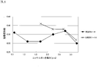
- 6 is a graph showing the results of measuring the surface hardness of the surface-treated steel sheets for battery containers of Examples 14 to 18 and Comparative Examples 16 to 20.
- the surface-treated steel sheet for battery containers according to the present invention is processed into an outer shape corresponding to a desired battery shape.
- the alkaline battery which is a primary battery, the nickel hydride battery which is a secondary battery, a lithium ion battery etc. can be illustrated, and it is based on this invention as a member of the battery container of these batteries.
- a surface-treated steel sheet for battery containers can be used.
- the present invention will be described in an embodiment in which the surface-treated steel sheet for a battery container according to the present invention is used for a positive electrode can constituting a battery container of an alkaline battery.
- FIG. 1 is a perspective view showing an embodiment of an alkaline battery 2 to which a surface-treated steel sheet for battery containers according to the present invention is applied
- FIG. 2 is a sectional view taken along the line II-II in FIG.
- the alkaline battery 2 of the present example is filled with a positive electrode mixture 23 and a negative electrode mixture 24 through a separator 25 in a bottomed cylindrical positive electrode can 21, and on the inner surface side of the opening of the positive electrode can 21, a negative electrode
- a sealing body composed of the terminal 22, the current collector 26 and the gasket 27 is caulked.
- a convex positive electrode terminal 211 is formed at the center of the bottom of the positive electrode can 21.
- the positive electrode can 21 is provided with an exterior 29 via an insulating ring 28 in order to impart insulation and improve design.
- the positive electrode can 21 of the alkaline battery 2 shown in FIG. 1 is obtained by subjecting the surface-treated steel sheet for battery containers according to the present invention to a deep drawing method, a drawing and ironing method (DI processing method), a drawing stretch processing method (DTR processing method), Alternatively, it can be obtained by forming by a processing method that uses stretching and ironing together after drawing.
- DI processing method drawing and ironing method
- DTR processing method drawing stretch processing method
- FIG. 3 is an enlarged cross-sectional view of a portion III in FIG. 2.
- the lower side is the inner surface of the alkaline battery 2 in FIG. 1 (the surface in contact with the positive electrode mixture 23 of the alkaline battery 2), and the upper side is the alkali. This corresponds to the outer surface of the battery 2.
- the surface-treated steel sheet 1 of this example shown in FIG. 3 has a matte or semi-glossy nickel plating layer 12 formed on both principal surfaces of the steel sheet 11 with respect to the steel sheet 11 constituting the base material of the surface-treated steel sheet 1. Further, a nickel-cobalt alloy plating layer 13 is formed on the nickel plating layer 12 on the surface which becomes the inner surface of the alkaline battery 2. Note that either one of the nickel plating layer 12 and the nickel-cobalt alloy plating layer 13 on the inner surface of the alkaline battery 2 may be omitted.
- the steel plate 11 of the present embodiment is not particularly limited as long as it has excellent formability, but, for example, a low carbon aluminum killed steel (carbon content 0.01 to 0.15 wt%), the carbon content is 0. 0.003 wt% or less of ultra-low carbon steel, or non-aging ultra-low carbon steel obtained by adding Ti, Nb or the like to ultra-low carbon steel can be used.
- a low carbon aluminum killed steel carbon content 0.01 to 0.15 wt%)
- the carbon content is 0. 0.003 wt% or less of ultra-low carbon steel
- non-aging ultra-low carbon steel obtained by adding Ti, Nb or the like can be used.
- these steel hot-rolled plates are pickled to remove the scale (oxide film) on the surface, then cold-rolled, and then subjected to electrolytic cleaning, followed by annealing and temper rolling.
- the annealing may be either continuous annealing or box annealing, and is not particularly limited.
- the nickel plating layer 12 is a matte or semi-gloss plating layer formed on at least the outer surface side of the steel plate 11 or both main surfaces by applying nickel plating to the steel plate 11 described above.
- nickel plating bath for forming the nickel plating layer 12
- nickel plating bath for forming the nickel plating layer 12
- the nickel plating layer 12 is formed by electroplating using a bath composition of 200 to 350 g / L nickel sulfate, 20 to 60 g / L nickel chloride, and 10 to 50 g / L boric acid as a watt bath. Can do.
- the nickel plating layer 12 may be matte or semi-glossy as described above.
- Examples of the method for forming the semi-bright nickel plating layer 12 include a method in which a semi-brightening agent is added to a nickel plating bath and the nickel plating layer is formed using the nickel plating bath to which the semi-brightening agent is added. .
- the glossiness is higher than when the matte nickel plating layer 12 is formed without using a semi-brightening agent.
- a semi-bright nickel plating with a nickel plating layer formed on the steel sheet so that the plating thickness is the same on a steel sheet having the same surface roughness Layer 12 plating conditions are current density 20 A / dm 2 , bath temperature 70 ° C.
- matte nickel plating layer 12 note that plating conditions are current density 20 A / dm 2 , bath temperature 60 ° C.
- the glossiness of the samples on which the semi-glossy nickel plating layer 12 was formed was measured as a glossiness using a gloss meter (VG-2000 manufactured by Nippon Denshoku Industries Co., Ltd.).
- the glossiness of the sample formed with 223.2 and the matte nickel plating layer 12 is 96.0, and a clear difference appears between them.
- the glossiness varies depending on the film thickness and surface roughness, but the semi-glossy nickel plating layer in this embodiment is measured by a gloss meter when the surface roughness Ra is 0.1 to 0.8 ⁇ m.
- the glossiness is usually 150 or more.
- the semi-brightening agent is not particularly limited as long as it does not contain sulfur, and examples thereof include aliphatic unsaturated alcohols such as polyoxy-ethylene adducts of unsaturated alcohols, unsaturated carboxylic acids, formaldehyde, and coumarins. Can be mentioned.
- a nickel plating layer is formed using a nickel plating bath to which substantially no brightener or semi-brightener is added. The method of doing is mentioned.
- the nickel plating layer 12 formed using such a nickel plating bath is measured by a glow discharge emission spectroscopic analyzer, the intensity of sulfur is below the noise level (or the intensity of the amount of impurities). In this case, the nickel plating layer 12 can be regarded as substantially free of sulfur.
- the ratio of S intensity obtained in the nickel plating layer 12 to Ni intensity (S intensity) / Ni strength) is, for example, about 0.00057 and less than 0.001 when matte and semi-gloss agents are used, while when using a gloss agent containing sulfur, for example, 0.00723.
- the ratio (S strength / Ni strength) is less than 0.001
- the nickel plating layer 12 It can be considered that substantially no sulfur is contained, and when the nickel plating layer 12 is glossy, the ratio (S strength / Ni strength) is 0.001 or more, and contains sulfur. It is possible to determine as.
- the HV for each element was nickel 700, iron 850, carbon 900, oxygen 700, and sulfur 999.
- the plating bath used for nickel plating includes a brightener (having an effect of refining the crystals constituting the nickel plating layer 12 and, as a result, increasing the surface hardness), in particular, an organic sulfur compound. It is preferable not to add an agent (for example, a brightener such as saccharin or sodium naphthalene sulfonate).
- a brightener such as saccharin or sodium naphthalene sulfonate.
- the additive made of an organic sulfur compound from being added to the plating bath, a problem caused by excessive sulfur in the nickel plating layer 12, that is, the obtained alkaline battery 2 is obtained.
- the contact resistance value of the nickel plating layer 12 constituting the battery container increases, and the battery performance of the alkaline battery 2 can be prevented from being deteriorated.
- an additive for example, a pit inhibitor
- a pit inhibitor having a small effect of increasing the surface hardness of the nickel plating layer 12 may be appropriately added to the plating bath.
- the bath temperature when forming the nickel plating layer 12 using the plating bath described above may be 70 ° C. or higher, preferably 70 to 80 ° C., more preferably 70 ° C. to 75 ° C.
- the bath temperature of the plating bath in the above range, the obtained nickel plating layer 12 has a higher surface hardness due to a smaller crystal grain size, and as a result, the press workability of the surface-treated steel sheet 1 is improved.
- the surface-treated steel plate 1 that is the outer surface of the alkaline battery 2 is matte or semi-glossy and has poor slidability
- the surface-treated steel plate The surface to which the surface-treated steel sheet 1 is pressed without being removed from the press die due to thermal expansion of the press die due to friction with the press die when the press 1 is pressed.
- a defect figging
- the nickel plating layer 12 In order to increase the hardness of the nickel plating layer 12 in a plating bath for forming the nickel plating layer 12 in order to prevent fogging of the surface-treated steel sheet 1 and seizure and wrinkling of the press mold. There is also a method in which the nickel plating layer 12 is formed on both principal surfaces of the steel plate 11 using this plating bath, but in this method, it is formed by the influence of sulfur or the like contained in the additive.
- the nickel plating layer 12 has an increased contact resistance value after long-term storage, and the alkaline battery 2 obtained using the nickel plated layer 12 has a decreased battery performance.
- the nickel plating layer 12 in order to prevent fogging of the surface-treated steel sheet 1 and seizure and wrinkling of the press mold, only the surface that is the outer surface of the alkaline battery 2 in the steel sheet 11 (the surface that is in contact with the press mold at the time of pressing), There is also a method of forming the nickel plating layer 12 using a plating bath to which an additive for increasing the hardness of the nickel plating layer 12 is added.
- the outer surface side and the inner surface side of the steel plate 11 are separately provided. Since it is necessary to use a plating bath, a bathtub for managing the plating bath must be added, and the nickel plating layer 12 must be individually formed on the outer surface side and the inner surface side of the steel plate 11. It is significantly reduced and disadvantageous in terms of cost.
- the bath temperature of the plating bath is set in the above range, so that the nickel plating layer 12 is formed as described above.
- the surface hardness of the surface-treated steel sheet 1 is reduced, so that the coefficient of dynamic friction between the nickel-plated layer 12 and the press die is reduced.
- the fogging of 1 and seizing and wrinkling of the press mold are effectively prevented, and the press workability of the surface-treated steel sheet 1 is improved.
- nickel plating is performed in one step (one pass) using a plating bath having the same composition on the surface of the steel plate 11 that is the outer surface of the alkaline battery 2 and the surface that is the inner surface of the alkaline battery 2. Since the plating layer 12 can be formed, the production efficiency of the surface-treated steel sheet 1 is improved, which is advantageous in terms of cost.
- the thickness of the nickel plating layer 12 on the outer surface and the inner surface may be the same, or may be different by changing the current density, and at least the outer surface is the nickel plating of this embodiment. Any layer 12 may be used.
- the surface-treated steel sheet 1 is obtained by incorporating sulfur into the nickel plating layer 12. The increase in the contact resistance value can be prevented. Furthermore, since it is not necessary to add an additive such as a brightener containing sulfur to the plating bath, the plating bath for other nickel plating products (nickel plating products that do not require the surface quality to be bright) The bathtub can be shared, and the production efficiency of the surface-treated steel sheet 1 and other nickel-plated products is improved.
- an additive such as a brightener
- the pH of the plating bath when forming the nickel plating layer 12 is preferably 2.0 to 5.3, more preferably 3.3 to 5.0, and even more preferably 3.8 to 4. .9.
- the pH of the plating bath is preferably 2.0 to 5.3, more preferably 3.3 to 5.0, and even more preferably 3.8 to 4. .9.
- the Vickers hardness (HV) measured with the load of 10 gf becomes like this.
- HV Vickers hardness
- the nickel plating layer 12 on the surface serving as the outer surface of the alkaline battery 2 in the surface-treated steel sheet 1 has a dynamic friction coefficient measured with a vertical load of 1 N / mm 2 , preferably 0.40 or less, more preferably 0.20 or less. is there.
- the pH of the plating bath is preferably 2.0 to 5.3, more preferably 3.3 to 5.0, It is preferably 3.8 to 4.9. is there.
- the current density when the nickel plating layer 12 is formed by electroplating is 12 A / dm 2 or more, preferably 12 to 40 A / dm 2 , more preferably 12 to 20 A / dm 2 , and particularly preferably 15 to 20 A / dm 2 .
- the hardness of the nickel plating layer 12 can be made high by making pH and current density of a plating bath into the said range.
- the nickel plating layer 12 can be formed in a shorter time, and the surface-treated steel sheet The production efficiency of 1 is improved.
- the inventors have increased the current density at the time of electroplating, while the hardness of the resulting nickel plating layer 12 tends to decrease, while the bath temperature at which the nickel plating layer 12 is formed, It has been found that by controlling to the above-described range, the hardness of the obtained nickel plating layer 12 can be increased even when the current density is set to a relatively high value as in the above range.
- the present inventors balance the bath temperature condition and the current density condition during electroplating within the above range, thereby producing the production efficiency of the surface-treated steel sheet 1. It has been found that the hardness of the nickel plating layer 12 constituting the surface-treated steel sheet 1 is increased while improving the hardness. As a result, the coefficient of dynamic friction between the surface-treated steel sheet 1 and the press die is reduced, heat generation when the surface-treated steel sheet 1 is pressed is suppressed, fogging of the surface-treated steel sheet 1, seizure of the press mold, and wrinkles. Can be effectively prevented.
- the nickel plating layer 12 of the present embodiment is matte or semi-glossy nickel plating.
- the arithmetic average roughness (Ra) of the surface of the nickel plating layer 12 is preferably 0.20 ⁇ m or more, more preferably 0.30 ⁇ m or more.
- the bath temperature and current density of the plating bath when forming the nickel plating layer 12 are as follows.
- the hardness of the nickel plating layer 12 is increased, whereby the coefficient of dynamic friction between the surface-treated steel sheet 1 and the press die is reduced, and heat generation when the surface-treated steel sheet 1 is pressed is suppressed. In addition, fogging of the surface-treated steel sheet 1 and seizing and wrinkling of the press mold can be effectively prevented.
- the presence ratio of the 200 planes among the 111 plane, the 200 plane, the 220 plane, and the 311 plane is preferably more than 40%. More preferably, it is 50% or more, More preferably, it is 70% or more.
- the present inventors when the present ratio of the above-mentioned 200 surface is high about the nickel plating layer 12, the present inventors become higher in the surface hardness of the nickel plating layer 12, and thereby the surface-treated steel sheet 1 obtained and the press We obtained knowledge that the coefficient of dynamic friction with the mold is lower. Therefore, the present inventors based on such knowledge, the nickel plating layer 12 formed on the outer surface side of the battery container has a higher surface hardness than the characteristics such as corrosion resistance, and press workability. As an example of a method for increasing the surface hardness of the nickel plating layer 12, the present inventors have found that the ratio of the 200 surfaces of the surface of the nickel plating layer 12 is preferably within the above range. .
- the method of setting the ratio of the 200 planes in the nickel plating layer 12 in the above range is not particularly limited.
- the bath temperature and current density of the plating bath when the nickel plating layer 12 is formed by electroplating are the above.
- the method of making it into a range is mentioned.
- the nickel plating layer 12 is formed on the steel plate 11 as described above.
- the nickel plating layer 12 may be formed directly on the steel plate 11, or a base layer is previously formed on the steel plate 11, and the nickel plating layer 12 is formed on the base layer. You may do it.
- the underlayer is not particularly limited, and examples thereof include an iron-nickel diffusion layer.
- the iron-nickel diffusion layer can be formed by heat-treating the steel plate 11 on which a nickel plating layer has been previously formed. That is, before the above-described nickel plating layer 12 is formed on the steel plate 11, a nickel plating layer for the base layer is formed on the steel plate 11, and the steel plate 11 on which the nickel plating layer for the base layer is formed is formed. By performing the heat treatment, the nickel plating layer for the underlayer can be thermally diffused, whereby an iron-nickel diffusion layer can be formed.
- it may be an iron-nickel diffusion layer in which iron is diffused to the surface of the nickel plating for the underlayer, or a part of the nickel plating layer for the underlayer remains softened by heat treatment without diffusing to the surface. Also good.
- the nickel plating layer 12 is formed on the steel plate 11 via the iron-nickel diffusion layer. The adhesion of the layer 12 to the steel plate 11 is improved. Further, by forming the iron-nickel diffusion layer as the base of the nickel plating layer 12, even when the thickness of the nickel plating layer 12 is thin, the hardness of the nickel plating layer 12 can be increased.
- the thickness of the nickel plating layer 12 is preferably 0.5 ⁇ m or more, more preferably 1.5 ⁇ m or more, and further preferably 2.0 ⁇ m. That's it.
- the upper limit of the thickness of the nickel plating layer 12 is not particularly limited, but is preferably 3.5 ⁇ m or less, more preferably 3.0 ⁇ m or less from the viewpoint of being advantageous in terms of cost.
- the hardness of the nickel plating layer 12 can be made high by making the thickness of the nickel plating layer 12 directly formed on the steel plate 11 into the above range.
- the thickness of the nickel plating layer 12 is preferably 0.5 ⁇ m or more, more preferably 1.0 ⁇ m. That's it.
- the upper limit of the thickness of the nickel plating layer 12 is not particularly limited, but is preferably 3.5 ⁇ m or less, more preferably 3.0 ⁇ m or less, and still more preferably 2. 5 ⁇ m or less.
- the hardness of the nickel plating layer 12 can be made high by making the thickness of the nickel plating layer 12 formed on the steel plate 11 through the base layer into the above range.
- the nickel-cobalt alloy plating layer 13 is a plating layer formed on the nickel plating layer 12 on the surface serving as the inner surface of the alkaline battery 2 by electroplating using a nickel-cobalt alloy plating bath.
- the conductivity of the obtained surface-treated steel sheet 1 is improved, and the alkaline battery 2 obtained by processing this is processed. Battery performance is improved.
- the nickel-cobalt alloy plating bath for forming the nickel-cobalt alloy plating layer 13 is not particularly limited. For example, it is based on a watt bath containing nickel sulfate, nickel chloride, cobalt sulfate and boric acid. A plating bath can be used.
- the cobalt / nickel ratio in the plating bath is preferably 0.10 to 0.29, more preferably 0.10 to 0.24 in terms of a cobalt / nickel molar ratio.
- the conditions for forming the nickel-cobalt alloy plating layer 13 are preferably a bath temperature of 40 to 80 ° C., a pH of 2.0 to 5.0, and a current density of 1 to 40 A / dm 2 .
- an edge mask is applied to the steel plate 11, and the nickel-cobalt alloy plating layer is formed on the nickel plating layer 12 on the outer surface of the alkaline battery 2. It is preferable that 13 is not formed.
- the thickness of the nickel-cobalt alloy plating layer 13 formed on the inner surface is preferably 0.1 to 0.4 ⁇ m, more preferably 0.15 to 0.2 ⁇ m.
- the effect of the present invention is not inhibited if it is preferably 0.03 ⁇ m or less, more preferably 0.01 ⁇ m or less, and most preferably not formed.
- the surface-treated steel sheet 1 of the present embodiment is configured as described above.
- the surface-treated steel sheet 1 of this embodiment is a deep drawing method, a drawing ironing method (DI processing method), a drawing stretch processing method (DTR processing method), or a processing method that uses ironing together with drawing after stretching.
- DI processing method drawing ironing method
- DTR processing method drawing stretch processing method
- the positive electrode can 21 of the alkaline battery 2 shown in FIGS. 1 and 2 and the battery container of other batteries are molded and used.
- the surface-treated steel sheet 1 of the present embodiment is excellent in press workability as described above, it is possible to use a low-viscosity press oil having excellent degreasing properties when being molded into a battery container, It is possible to easily degrease the press oil after the molding process. That is, when the press oil has a high viscosity, it tends to be easy to prevent the press mold from being wrinkled, but it becomes difficult to degrease the press oil after press working. In the steel plate 1, even when a low-viscosity press oil is used, the press mold can be prevented from being wrinkled, so that the press oil after the press working can be easily degreased and washed.
- a steel plate for constituting the steel plate 11 is prepared, and the nickel plating layer 12 is formed on both main surfaces of the steel plate 11 by applying nickel plating to the steel plate 11 as described above.
- the nickel plating layer 12 from which a composition, surface roughness, etc. differ, using the plating bath of a different composition on the surface used as the outer surface of the alkaline battery 2 in the steel plate 11, and the surface used as the inner surface of the alkaline battery 2, respectively.
- the bath temperature at the time of plating shall be 70 degreeC or more.
- the steel plate 11 and the nickel plating layer 12 are not thermally diffused after the nickel plating layer 12 is formed. That is, since the iron constituting the steel plate 11 is lower in hardness than nickel, when the iron of the steel plate 11 is thermally diffused into the nickel plating layer 12, the hardness of the nickel plating layer 12 is lowered, and the press workability of the surface-treated steel plate 1 obtained is reduced. May decrease. Therefore, in this embodiment, the hardness of the nickel plating layer 12 can be made high by not performing the thermal diffusion process of the steel plate 11 or the nickel plating layer 12, and the press workability of the surface-treated steel plate 1 can be increased. Will improve.
- a nickel-cobalt alloy plating layer 13 is formed on the nickel plating layer 12 on the surface serving as the inner surface of the alkaline battery 2 by electroplating using a nickel-cobalt alloy plating bath.
- the surface-treated steel sheet 1 shown in 3 is obtained.
- the surface-treated steel sheet 1 of this embodiment is manufactured.
- the bath temperature of the plating bath is set to 70 ° C. or higher so that the nickel plating layer 12
- the surface hardness is increased, and thereby the dynamic friction coefficient between the nickel plating layer 12 and the press die is lowered.
- frictional heat generated when the surface-treated steel sheet 1 is pressed is suppressed, and fogging of the surface-treated steel sheet 1 and seizure and wrinkling of the press mold are effectively prevented.
- 1 press workability improves.
- the surface-treated steel sheet 1 of the present embodiment is suitably used as a battery container formed by pressing, for example, a battery using an alkaline electrolyte such as an alkaline battery or a nickel metal hydride battery, or a battery container such as a lithium ion battery. Can be used.
- a battery container formed by pressing for example, a battery using an alkaline electrolyte such as an alkaline battery or a nickel metal hydride battery, or a battery container such as a lithium ion battery. Can be used.
- the surface-treated steel sheet 1 of the present embodiment is a battery that is scheduled to be stored or mounted for a long period of time, in particular, a storage battery for use in an emergency such as an earthquake disaster, a remote control of an electrical product, a flashlight, etc. It can use suitably as a battery container of the battery used for.
- the Vickers hardness (HV) is measured by a micro hardness tester (manufactured by Akashi Seisakusho Co., Ltd., model number: MVK-G2) using a diamond indenter under conditions of load: 10 gf and holding time: 10 seconds
- HV Vickers hardness
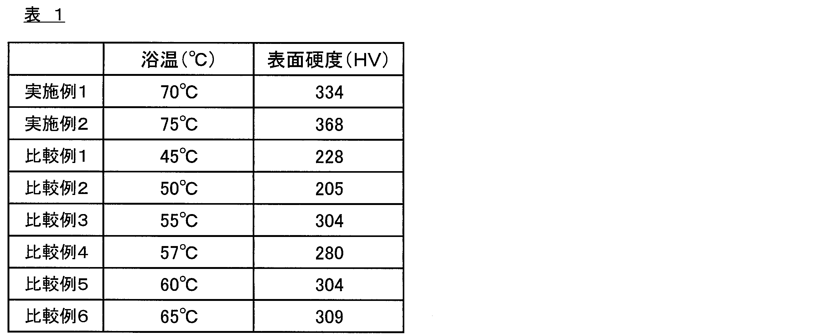
- Example 1 A steel plate 11 obtained by annealing a cold rolled plate (thickness 0.25 mm) of low carbon aluminum killed steel was prepared as a substrate.
- Example 2 A surface-treated steel sheet 1 was produced in the same manner as in Example 1 except that the bath temperature when forming the nickel plating layer 12 was 75 ° C., and the surface hardness was measured in the same manner. The results are shown in Table 1 and FIG.
- Comparative Examples 1 to 6 The bath temperature when forming the nickel plating layer 12 is 45 ° C. (Comparative Example 1), 50 ° C. (Comparative Example 2), 55 ° C. (Comparative Example 3), 57 ° C. (Comparative Example 4), 60 ° C. (Comparative Example 5).
- the surface-treated steel sheet 1 was produced in the same manner as in Example 1 except that the temperature was 65 ° C. (Comparative Example 6), and the surface hardness was measured in the same manner. The results are shown in Table 1 and FIG.
- Examples 3 to 8 Surface-treated steel sheet in the same manner as in Example 1 except that the thickness of the nickel plating layer 12 is shown in Table 2 by adjusting the current density and energization time of the electrolytic plating when forming the nickel plating layer 12. 1 was produced. And about the obtained surface-treated steel plate 1, according to the method mentioned above, the surface hardness and the dynamic friction coefficient were measured. The results are shown in Table 2 and FIGS.
- Example 1 except that the bath temperature at the time of forming the nickel plating layer 12 is 60 ° C., and the thickness of the nickel plating layer 12 is as shown in Table 2 by adjusting the current density and energization time of electrolytic plating.
- a surface-treated steel sheet 1 was produced in the same manner as described above. And about the obtained surface-treated steel plate 1, according to the method mentioned above, the surface hardness and the dynamic friction coefficient were measured. The results are shown in Table 2 and FIGS.
- Examples 3 to 8 in which the bath temperature when forming the nickel plating layer 12 was set to 70 ° C. or more and the thickness of the nickel plating layer 12 was changed are comparative examples. Compared with 7 to 10, the measured value of the dynamic friction coefficient of the nickel plating layer 12 was relatively low.
- the surface-treated steel sheet 1 of Examples 1 to 8 effectively prevents fogging of the surface-treated steel sheet 1 during press working, seizure and wrinkling of the press mold, and has excellent press workability. It is believed that there is.
- Example 9 As an original plate, a steel plate 11 obtained by annealing a cold rolled plate (thickness 0.30 mm) of low carbon aluminum killed steel having the chemical composition shown below was prepared.
- a surface-treated steel sheet 1 having nickel plating layers 12 formed on both main surfaces of the steel sheet 11 was obtained.
- the surface-treated steel sheet 1 obtained was measured for surface hardness and dynamic friction coefficient according to the above-described method.
- the results are shown in Table 3 and FIG.
- the horizontal axis is the bath temperature of the plating bath
- the surface hardness value (left vertical axis) is a line graph
- the dynamic friction coefficient value (right vertical axis) is a bar graph.
- the abundance ratio (111 plane, 200 plane, 220 plane, 200 plane crystal orientation) of the surface of the nickel plating layer 12 And the presence ratio of 200 planes among the 311 planes) was 75.2%.
- the glossiness of the surface of the nickel plating layer 12 measured using a gloss meter Nippon Denshoku Industries Co., Ltd., VG-2000
- Examples 10 to 12 By changing the bath temperature and current density of the plating bath when forming the nickel plating layer 12 as shown in Table 3 and adjusting the energization time, the thickness of the nickel plating layer 12 becomes 2.0 ⁇ m.
- the surface-treated steel sheet 1 was produced in the same manner as in Example 9 except that the control was performed and evaluated in the same manner. The results are shown in Table 3 and FIG.
- the existence ratios of the crystal orientation 200 plane on the surface of the nickel plating layer 12 were 86.3% (Example 10) and 58.2% (Examples), respectively. 11) and 59.9% (Example 12).
- the glossiness of the surface of the nickel plating layer 12 was 223.2.
- Comparative Examples 11-15 By changing the bath temperature and current density of the plating bath when forming the nickel plating layer 12 as shown in Table 3 and adjusting the energization time, the thickness of the nickel plating layer 12 becomes 2.0 ⁇ m.
- the surface-treated steel sheet 1 was produced in the same manner as in Example 9 except that the control was performed and evaluated in the same manner. The results are shown in Table 3 and FIG. In the surface-treated steel sheets 1 of Comparative Examples 11 to 15, the existence ratios of the crystal orientation 200 plane on the surface of the nickel plating layer 12 were 46.6% (Comparative Example 11) and 81.2% (Comparative Example), respectively.
- the surface-treated steel sheets 1 of Comparative Examples 11 to 15 in which the bath temperature when forming the nickel plating layer 12 is less than 70 ° C. have the same nickel plating layer 12 thickness.
- the surface hardness is low and the dynamic friction coefficient is high, so it is considered that the press workability is inferior.
- Example 13 As an original plate, a steel plate 11 obtained by annealing a cold rolled plate (thickness 0.25 mm) of low carbon aluminum killed steel having the chemical composition shown below was prepared.
- the steel plate 11 on which the nickel plating layer is formed is subjected to a thermal diffusion treatment under the conditions of a heat treatment temperature of 720 ° C., a heat treatment time of 1 minute, and a reducing atmosphere by continuous annealing, thereby providing an iron-nickel diffusion layer as an underlayer. Formed.
- HV surface hardness
- the surface-treated steel sheet 1 obtained was measured for surface hardness and dynamic friction coefficient according to the above-described method.
- the results are shown in Table 4 and FIG.
- the horizontal axis represents the bath temperature of the plating bath, and the vertical axis represents the surface hardness value.
- the existence ratio of the crystal orientation 200 plane on the surface of the nickel plating layer 12 was 61.88%.
- the glossiness of the surface of the nickel plating layer 12 was 163.7.
- Examples 14 to 18 The surface-treated steel sheet 1 was prepared in the same manner as in Example 13 except that the thickness of the nickel plating layer 12 was shown in Table 4 by adjusting the energization time when forming the nickel plating layer 12. Evaluated. The results are shown in Table 4 and FIG. In the surface-treated steel sheets 1 of Examples 14 to 18, the presence ratios of the crystal orientation 200 plane on the surface of the nickel plating layer 12 were 72.53% (Example 14) and 75.83% (Examples), respectively. 15), 82.27% (Example 16), 86.00% (Example 17), and 87.81% (Example 18). Moreover, in the surface treatment steel plate 1 of Example 16, the glossiness of the surface of the nickel plating layer 12 was 229.9.
- Table 4 shows the thickness of the nickel plating layer 12 by changing the bath temperature of the plating bath when forming the nickel plating layer 12 to 60 ° C. and adjusting the energization time when forming the nickel plating layer 12.
- a surface-treated steel sheet 1 was produced in the same manner as in Example 13 except that it was shown, and was similarly evaluated. The results are shown in Table 4 and FIG.
- the presence ratios of the crystal orientation 200 plane on the surface of the nickel plating layer 12 were 72.61% (Comparative Example 16) and 74.76% (Comparative Example), respectively.
- Example 14 and Comparative Example 16 in which the thickness of the nickel plating layer 12 was 1.0 ⁇ m were compared, Example 14 had a higher surface hardness than Comparative Example 16.
- Example 15 and Comparative Example 17 in which the thickness of the nickel plating layer 12 is 1.5 ⁇ m
- Example 16 and Comparative Example 18 in which the thickness is 2.0 ⁇ m
- Example 17 and Comparative Examples 19 and 3 in which the thickness is 2.5 ⁇ m.
- Example 18 and Comparative Example 20 which are 0.0 ⁇ m
- the surface hardness of each Example was higher than that of the Comparative Example.
- the surface-treated steel sheets 1 of Examples 13 to 18 were considered to have a low dynamic friction coefficient because the surface hardness was a high value.
Landscapes
- Chemical & Material Sciences (AREA)
- Chemical Kinetics & Catalysis (AREA)
- Electrochemistry (AREA)
- Engineering & Computer Science (AREA)
- Organic Chemistry (AREA)
- Metallurgy (AREA)
- Materials Engineering (AREA)
- Crystallography & Structural Chemistry (AREA)
- General Chemical & Material Sciences (AREA)
- Mechanical Engineering (AREA)
- Electroplating Methods And Accessories (AREA)
- Sealing Battery Cases Or Jackets (AREA)
- Electroplating And Plating Baths Therefor (AREA)
Abstract
Description
本発明の製造方法において、前記めっき処理の後には、前記ニッケルめっき層の熱拡散処理を行わないことが好ましい。
本発明の製造方法において、前記めっき処理により、10g荷重におけるマイクロビッカース硬さ(HV)が280以上である前記ニッケルめっき層を形成することが好ましい。
本発明の製造方法において、前記めっき処理により、垂直荷重1N/mm2で測定した動摩擦係数が0.40以下である前記ニッケルめっき層を形成することが好ましい。
本発明の製造方法において、前記めっき処理により、厚みが2.0μm以上の前記ニッケルめっき層を形成することが好ましい。
本発明の製造方法において、前記めっき処理により、電池容器の外面側となる面及び内面側となる面の両面に前記ニッケルめっき層を形成することが好ましい。
本発明の製造方法において、電池容器の内面側となる面に形成した前記ニッケルめっき層上に、ニッケル-コバルト合金めっき層をさらに形成することが好ましい。
本発明の製造方法において、厚みが0.03μm以下である前記ニッケル-コバルト合金めっき層を形成することが好ましい。
また、本発明によれば、上述した製造方法により得られた電池容器を用いてなる電池の製造方法が提供される。
また、本発明によれば、鋼板における少なくとも電池容器の外面側となる面に、鉄-ニッケル拡散層からなる下地層と、無光沢又は半光沢のニッケルめっき層とが、この順で形成されてなる電池容器用表面処理鋼板であって、前記ニッケルめっき層は、厚みが0.5~3.5μmであり、かつ、負荷荷重100gfで測定した場合における表面の動摩擦係数が、0.4以下である電池容器用表面処理鋼板が提供される。
本実施形態の鋼板11としては、成形加工性に優れているものであればよく特に限定されないが、例えば、低炭素アルミキルド鋼(炭素量0.01~0.15重量%)、炭素量が0.003重量%以下の極低炭素鋼、又は極低炭素鋼にTiやNbなどを添加してなる非時効性極低炭素鋼を用いることができる。
ニッケルめっき層12は、上述した鋼板11にニッケルめっきを施すことにより鋼板11の少なくとも外面側となる面、または両主面に形成され、無光沢又は半光沢のめっき層である。
特に、本発明者等は、電気めっきを行う際の電流密度を高くすると、得られるニッケルめっき層12の硬度が低下する傾向にある一方で、ニッケルめっき層12を形成する際の浴温を、上述した範囲に制御することにより、電流密度を上記範囲のように比較的高い値とした場合においても、得られるニッケルめっき層12の硬度を高くすることができるとの知見を得た。そして、本発明者等は、このような知見に基づき、電気めっきを行う際の浴温の条件と、電流密度の条件とを、上記範囲内でバランスさせることにより、表面処理鋼板1の生産効率を向上させながら、表面処理鋼板1を構成するニッケルめっき層12の硬度を高くすることを見出した。これにより、表面処理鋼板1とプレス金型との動摩擦係数が低下し、表面処理鋼板1をプレス加工する際の発熱が抑制され、表面処理鋼板1のカブリや、プレス金型の焼き付き及び疵付きを有効に防止できる。
ニッケル-コバルト合金めっき層13は、ニッケル-コバルト合金めっき浴を用いた電気めっきにより、アルカリ電池2の内面となる面のニッケルめっき層12に形成されるめっき層である。本実施形態では、アルカリ電池2の内面となる面にニッケル-コバルト合金めっき層13を形成することにより、得られる表面処理鋼板1の導電性が向上し、これを加工して得られるアルカリ電池2の電池性能が向上する。
次いで、本実施形態の表面処理鋼板1の製造方法について、説明する。
なお、各特性の評価方法は、以下のとおりである。
表面処理鋼板1について、微小硬度計(株式会社明石製作所製、型番:MVK-G2)により、ダイヤモンド圧子を用いて、荷重:10gf、保持時間:10秒の条件でビッカース硬度(HV)を測定することにより、ニッケルめっき層12の表面硬度の測定を行った。
表面処理鋼板1について、トライボメータ(CSEM社製、接触子:SUJ-2(クロムスチール鋼))を用いて、負荷荷重:100gf、10回転後の記録チャートから読み取り、垂直荷重1N/mm2の条件で動摩擦係数を測定した。
基体として、低炭素アルミキルド鋼の冷間圧延板(厚さ0.25mm)を焼鈍して得られた鋼板11を準備した。
浴組成:硫酸ニッケル250g/L、塩化ニッケル45g/L、ホウ酸45g/L
pH:4.3
浴温:70℃
電流密度:20A/dm2
通電時間:35秒
ニッケルめっき層12を形成する際の浴温を75℃にした以外は、実施例1と同様にして表面処理鋼板1を作製し、同様に表面硬度の測定を行った。結果を表1及び図4に示す。
ニッケルめっき層12を形成する際の浴温を45℃(比較例1)、50℃(比較例2)、55℃(比較例3)、57℃(比較例4)、60℃(比較例5)、65℃(比較例6)にした以外は、実施例1と同様にして表面処理鋼板1を作製し、同様に表面硬度の測定を行った。結果を表1及び図4に示す。
ニッケルめっき層12を形成する際の電解めっきの電流密度及び通電時間を調整することで、ニッケルめっき層12の厚みを表2に示すようにした以外は、実施例1と同様にして表面処理鋼板1を作製した。そして、得られた表面処理鋼板1について、上述した方法にしたがって表面硬度及び動摩擦係数の測定を行った。結果を表2及び図5,6に示す。
ニッケルめっき層12を形成する際の浴温を60℃とし、電解めっきの電流密度及び通電時間を調整することで、ニッケルめっき層12の厚みを表2に示すようにした以外は、実施例1と同様にして表面処理鋼板1を作製した。そして、得られた表面処理鋼板1について、上述した方法にしたがって表面硬度及び動摩擦係数の測定を行った。結果を表2及び図5,6に示す。

原板として、下記に示す化学組成を有する低炭素アルミキルド鋼の冷間圧延板(厚さ0.30mm)を焼鈍して得られた鋼板11を準備した。
C:0.001重量%、Mn:0.160重量%、Si:0.010重量%、P:0.011重量%、S:0.007重量%、Al:0.036重量%、N:0.00021重量%、残部:Feおよび不可避的不純物
浴組成:硫酸ニッケル250g/L、塩化ニッケル45g/L、ホウ酸45g/L
pH:3.9~4.9
浴温:70℃
電流密度:15A/dm2
ニッケルめっき層12を形成する際のめっき浴の浴温及び電流密度を、それぞれ表3に示すように変更し、さらに通電時間を調整することでニッケルめっき層12の厚みが2.0μmとなるように制御した以外は、実施例9と同様にして表面処理鋼板1を作製し、同様に評価した。結果を表3及び図7に示す。なお、実施例10~12の表面処理鋼板1においては、ニッケルめっき層12の表面の結晶方位200面の存在割合は、それぞれ、86.3%(実施例10)、58.2%(実施例11)、59.9%(実施例12)であった。また、実施例10の表面処理鋼板1においては、ニッケルめっき層12の表面の光沢度は223.2であった。
ニッケルめっき層12を形成する際のめっき浴の浴温及び電流密度を、それぞれ表3に示すように変更し、さらに通電時間を調整することでニッケルめっき層12の厚みが2.0μmとなるように制御した以外は、実施例9と同様にして表面処理鋼板1を作製し、同様に評価した。結果を表3及び図7に示す。なお、比較例11~15の表面処理鋼板1においては、ニッケルめっき層12の表面の結晶方位200面の存在割合は、それぞれ、46.6%(比較例11)、81.2%(比較例12)、72.4%(比較例13)、88.4%(比較例14)、85.8%(比較例15)であった。また、比較例14,15の表面処理鋼板1においては、ニッケルめっき層12の表面の光沢度は、219.8(比較例14)、225.8(比較例15)であった。

原板として、下記に示す化学組成を有する低炭素アルミキルド鋼の冷間圧延板(厚さ0.25mm)を焼鈍して得られた鋼板11を準備した。
C:0.03重量%、Mn:0.18重量%、Si:Trace重量%、P:0.013重量%、S:0.005重量%、Al:0.049重量%、N:0.00017重量%、残部:Feおよび不可避的不純物
次いで、準備した鋼板11について、アルカリ電解脱脂、硫酸浸漬の酸洗を行った後、下記条件にて電解めっきを行い、鋼板11上に厚さ0.25μmのニッケルめっき層を形成した。
浴組成:硫酸ニッケル250g/L、塩化ニッケル45g/L、ホウ酸45g/L
pH:3.9~4.9
浴温:60℃
電流密度:15A/dm2
次いで、下地層(鉄-ニッケル拡散層)を形成した鋼板11に対して、下記条件にて電解めっきを行い、鋼板11上に厚さ0.5μmのニッケルめっき層12を形成することで、鋼板11の両主面にニッケルめっき層12が形成されてなる表面処理鋼板1を得た。
浴組成:硫酸ニッケル250g/L、塩化ニッケル45g/L、ホウ酸45g/L、半光沢剤(リーベライトSB-71およびリーベライトSB-72)4ml/L
pH:3.9~4.9
浴温:70℃
電流密度:15A/dm2
ニッケルめっき層12を形成する際の通電時間を調整することで、ニッケルめっき層12の厚みを表4に示すようにした以外は、実施例13と同様にして表面処理鋼板1を作製し、同様に評価した。結果を表4及び図8に示す。なお、実施例14~18の表面処理鋼板1においては、ニッケルめっき層12の表面の結晶方位200面の存在割合は、それぞれ、72.53%(実施例14)、75.83%(実施例15)、82.27%(実施例16)、86.00%(実施例17)、87.81%(実施例18)であった。また、実施例16の表面処理鋼板1においては、ニッケルめっき層12の表面の光沢度は229.9であった。
ニッケルめっき層12を形成する際のめっき浴の浴温を60℃に変更し、さらに、ニッケルめっき層12を形成する際の通電時間を調整することで、ニッケルめっき層12の厚みを表4に示すようにした以外は、実施例13と同様にして表面処理鋼板1を作製し、同様に評価した。結果を表4及び図8に示す。なお、比較例16~20の表面処理鋼板1においては、ニッケルめっき層12の表面の結晶方位200面の存在割合は、それぞれ、72.61%(比較例16)、74.76%(比較例17)、82.88%(比較例18)、85.04%(比較例19)、88.56%(比較例20)であった。また、実施例18の表面処理鋼板1においては、ニッケルめっき層12の表面の光沢度は271.8であった。
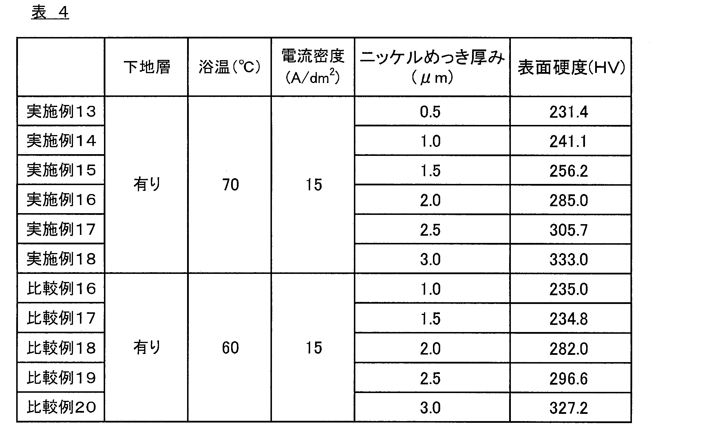
また、表4及び図8に示すように、ニッケルめっき層12を形成する際の浴温を70℃以上とし、めっきを行う際の電流密度を12A/dm2以上とした実施例14~18の表面処理鋼板1は、ニッケルめっき層12の厚みが同じである比較例11~15と比較して、表面硬度が高い値であった。すなわち、ニッケルめっき層12の厚みが1.0μmである実施例14と比較例16とを比較した場合に、実施例14の方が、比較例16より表面硬度が高い値であった。同様に、ニッケルめっき層12の厚みが1.5μmである実施例15及び比較例17、2.0μmである実施例16及び比較例18、2.5μmである実施例17及び比較例19、3.0μmである実施例18及び比較例20についても、それぞれ実施例のほうが比較例より表面硬度が高い値であった。
これにより、実施例13~18の表面処理鋼板1は、表面硬度が高い値であったことから、動摩擦係数が低い値になると考えられる。
11…鋼板
12…ニッケルめっき層
13…ニッケル-コバルト合金めっき層
2…アルカリ電池
21…正極缶
211…正極端子
22…負極端子
23…正極合剤
24…負極合剤
25…セパレータ
26…集電体
27…ガスケット
28…絶縁リング
29…外装
Claims (13)
- 鋼板における少なくとも電池容器の外面側となる面に、無光沢又は半光沢のニッケルめっき層を形成する電池容器用表面処理鋼板の製造方法において、
浴温70℃以上の条件でめっき処理を行うことで前記ニッケルめっき層を形成する電池容器用表面処理鋼板の製造方法。 - 前記めっき処理には、有機硫黄化合物が添加されていないめっき浴を用いる請求項1に記載の電池容器用表面処理鋼板の製造方法。
- 前記めっき処理の後には、前記ニッケルめっき層の熱拡散処理を行わない請求項1又は2に記載の電池容器用表面処理鋼板の製造方法。
- 前記めっき処理により、10g荷重におけるマイクロビッカース硬さ(HV)が280以上である前記ニッケルめっき層を形成する請求項1~3の何れか一項に記載の電池容器用表面処理鋼板の製造方法。
- 前記めっき処理により、垂直荷重1N/mm2で測定した動摩擦係数が0.40以下である前記ニッケルめっき層を形成する請求項1~4の何れか一項に記載の電池容器用表面処理鋼板の製造方法。
- 前記めっき処理により、厚みが2.0μm以上の前記ニッケルめっき層を形成する請求項1~5の何れか一項に記載の電池容器用表面処理鋼板の製造方法。
- 前記めっき処理により、電池容器の外面側となる面及び内面側となる面の両面に前記ニッケルめっき層を形成する請求項1~6の何れか一項に記載の電池容器用表面処理鋼板の製造方法。
- 電池容器の内面側となる面に形成した前記ニッケルめっき層上に、ニッケル-コバルト合金めっき層をさらに形成する請求項7に記載の電池容器用表面処理鋼板の製造方法。
- 厚みが0.03μm以下である前記ニッケル-コバルト合金めっき層を形成する請求項8に記載の電池容器用表面処理鋼板の製造方法。
- 請求項1~9の何れかに記載の製造方法により得られた電池容器用表面処理鋼板を成形加工してなる電池容器の製造方法。
- 請求項10に記載の製造方法により得られた電池容器を用いてなる電池の製造方法。
- 鋼板における少なくとも電池容器の外面側となる面に、無光沢又は半光沢のニッケルめっき層が形成されてなる電池容器用表面処理鋼板であって、
前記ニッケルめっき層は、厚みが0.5~3.5μmであり、かつ、負荷荷重100gfで測定した場合における表面の動摩擦係数が、0.4以下である電池容器用表面処理鋼板。 - 鋼板における少なくとも電池容器の外面側となる面に、鉄-ニッケル拡散層からなる下地層と、無光沢又は半光沢のニッケルめっき層とが、この順で形成されてなる電池容器用表面処理鋼板であって、
前記ニッケルめっき層は、厚みが0.5~3.5μmであり、かつ、負荷荷重100gfで測定した場合における表面の動摩擦係数が、0.4以下である電池容器用表面処理鋼板。
Priority Applications (5)
| Application Number | Priority Date | Filing Date | Title |
|---|---|---|---|
| KR1020177026440A KR102513977B1 (ko) | 2015-03-13 | 2016-03-11 | 전지 용기용 표면 처리 강판의 제조 방법 및 전지 용기용 표면 처리 강판 |
| CN201680014529.6A CN107407000B (zh) | 2015-03-13 | 2016-03-11 | 电池容器用表面处理钢板的制造方法和电池容器用表面处理钢板 |
| US15/557,937 US10910607B2 (en) | 2015-03-13 | 2016-03-11 | Method for producing surface-treated steel sheet for battery containers and surface-treated steel sheet for battery containers |
| EP16764914.4A EP3269847A4 (en) | 2015-03-13 | 2016-03-11 | Method for producing surface-treated steel sheet for battery containers, and surface-treated steel sheet for battery containers |
| JP2017506535A JP6798979B2 (ja) | 2015-03-13 | 2016-03-11 | 電池容器用表面処理鋼板の製造方法、及び電池容器用表面処理鋼板 |
Applications Claiming Priority (2)
| Application Number | Priority Date | Filing Date | Title |
|---|---|---|---|
| JP2015050543 | 2015-03-13 | ||
| JP2015-050543 | 2015-03-13 |
Publications (1)
| Publication Number | Publication Date |
|---|---|
| WO2016148084A1 true WO2016148084A1 (ja) | 2016-09-22 |
Family
ID=56919955
Family Applications (1)
| Application Number | Title | Priority Date | Filing Date |
|---|---|---|---|
| PCT/JP2016/057846 Ceased WO2016148084A1 (ja) | 2015-03-13 | 2016-03-11 | 電池容器用表面処理鋼板の製造方法、及び電池容器用表面処理鋼板 |
Country Status (6)
| Country | Link |
|---|---|
| US (1) | US10910607B2 (ja) |
| EP (1) | EP3269847A4 (ja) |
| JP (1) | JP6798979B2 (ja) |
| KR (1) | KR102513977B1 (ja) |
| CN (1) | CN107407000B (ja) |
| WO (1) | WO2016148084A1 (ja) |
Cited By (1)
| Publication number | Priority date | Publication date | Assignee | Title |
|---|---|---|---|---|
| JP2018168396A (ja) * | 2017-03-29 | 2018-11-01 | 日本軽金属株式会社 | アルミニウム合金製車載用バスバー及びその製造方法 |
Families Citing this family (2)
| Publication number | Priority date | Publication date | Assignee | Title |
|---|---|---|---|---|
| CN116325265A (zh) * | 2020-10-15 | 2023-06-23 | 株式会社村田制作所 | 二次电池 |
| KR102477435B1 (ko) * | 2020-12-09 | 2022-12-15 | 주식회사 티씨씨스틸 | 가공성이 우수한 니켈 도금 열처리 강판 및 이의 제조방법 |
Citations (3)
| Publication number | Priority date | Publication date | Assignee | Title |
|---|---|---|---|---|
| JP2000082446A (ja) * | 1998-07-10 | 2000-03-21 | Toshiba Battery Co Ltd | アルカリ乾電池 |
| WO2012147843A1 (ja) * | 2011-04-28 | 2012-11-01 | 東洋鋼鈑株式会社 | 電池容器用表面処理鋼板、電池容器および電池 |
| JP2014047359A (ja) * | 2012-08-29 | 2014-03-17 | Toyo Kohan Co Ltd | 電池容器用表面処理鋼板、電池容器および電池 |
Family Cites Families (10)
| Publication number | Priority date | Publication date | Assignee | Title |
|---|---|---|---|---|
| BE789793A (fr) * | 1971-10-06 | 1973-04-06 | Hoesch Ag | Procede de pretraitement de bandes et de toles en acier en vue d'un emaillage en une seule couche |
| JP4130989B2 (ja) | 1998-08-10 | 2008-08-13 | 東芝電池株式会社 | アルカリ乾電池 |
| JP4808834B2 (ja) * | 2000-08-04 | 2011-11-02 | 東洋鋼鈑株式会社 | 電池ケース用表面処理鋼板 |
| KR100696929B1 (ko) * | 2002-04-22 | 2007-03-20 | 도요 고한 가부시키가이샤 | 전지 케이스용 표면 처리 강판, 전지 케이스 및 그것을사용한 전지 |
| JP4216611B2 (ja) * | 2003-01-17 | 2009-01-28 | 新日本製鐵株式会社 | 電池缶用Niメッキ鋼板 |
| JP5128900B2 (ja) * | 2007-10-25 | 2013-01-23 | 日立ビークルエナジー株式会社 | リチウム二次電池、および、その製造方法 |
| CN102458701A (zh) * | 2009-06-09 | 2012-05-16 | 东洋钢钣株式会社 | 镀Ni钢板及使用该镀Ni钢板的电池壳的制造方法 |
| KR101821659B1 (ko) * | 2010-01-08 | 2018-01-25 | 도요 고한 가부시키가이샤 | 표면처리금속판 및 그 표면처리금속판을 이용한 성형품의 제조방법 |
| WO2011083562A1 (ja) * | 2010-01-08 | 2011-07-14 | 東洋鋼鈑株式会社 | プレス性に優れた電池缶用Niめっき鋼板 |
| JP2014009401A (ja) * | 2012-07-03 | 2014-01-20 | Toyo Kohan Co Ltd | 電池容器用表面処理鋼板およびその製造方法、電池容器および電池 |
-
2016
- 2016-03-11 EP EP16764914.4A patent/EP3269847A4/en not_active Withdrawn
- 2016-03-11 US US15/557,937 patent/US10910607B2/en active Active
- 2016-03-11 KR KR1020177026440A patent/KR102513977B1/ko active Active
- 2016-03-11 JP JP2017506535A patent/JP6798979B2/ja active Active
- 2016-03-11 CN CN201680014529.6A patent/CN107407000B/zh active Active
- 2016-03-11 WO PCT/JP2016/057846 patent/WO2016148084A1/ja not_active Ceased
Patent Citations (3)
| Publication number | Priority date | Publication date | Assignee | Title |
|---|---|---|---|---|
| JP2000082446A (ja) * | 1998-07-10 | 2000-03-21 | Toshiba Battery Co Ltd | アルカリ乾電池 |
| WO2012147843A1 (ja) * | 2011-04-28 | 2012-11-01 | 東洋鋼鈑株式会社 | 電池容器用表面処理鋼板、電池容器および電池 |
| JP2014047359A (ja) * | 2012-08-29 | 2014-03-17 | Toyo Kohan Co Ltd | 電池容器用表面処理鋼板、電池容器および電池 |
Non-Patent Citations (1)
| Title |
|---|
| See also references of EP3269847A4 * |
Cited By (2)
| Publication number | Priority date | Publication date | Assignee | Title |
|---|---|---|---|---|
| JP2018168396A (ja) * | 2017-03-29 | 2018-11-01 | 日本軽金属株式会社 | アルミニウム合金製車載用バスバー及びその製造方法 |
| JP7162413B2 (ja) | 2017-03-29 | 2022-10-28 | 日本軽金属株式会社 | アルミニウム合金製車載用バスバー及びその製造方法 |
Also Published As
| Publication number | Publication date |
|---|---|
| US20180062121A1 (en) | 2018-03-01 |
| JPWO2016148084A1 (ja) | 2018-02-01 |
| CN107407000A (zh) | 2017-11-28 |
| EP3269847A1 (en) | 2018-01-17 |
| CN107407000B (zh) | 2019-09-13 |
| EP3269847A4 (en) | 2018-11-07 |
| JP6798979B2 (ja) | 2020-12-09 |
| US10910607B2 (en) | 2021-02-02 |
| KR20170128343A (ko) | 2017-11-22 |
| KR102513977B1 (ko) | 2023-03-23 |
Similar Documents
| Publication | Publication Date | Title |
|---|---|---|
| US11699824B2 (en) | Nickel-plated, heat-treated steel sheet for battery cans | |
| KR102479919B1 (ko) | 전지 용기용 표면 처리 강판의 제조 방법 | |
| JP5570078B2 (ja) | Niめっき鋼板及びそのNiめっき鋼板を用いた電池缶の製造方法 | |
| KR100436326B1 (ko) | 전지케이스및전지케이스용표면처리강판 | |
| KR20030020437A (ko) | 전지 케이스용 표면처리강판 및 전지 케이스 | |
| WO2016148084A1 (ja) | 電池容器用表面処理鋼板の製造方法、及び電池容器用表面処理鋼板 | |
| JP3272866B2 (ja) | アルカリ電池ケース用表面処理鋼板、アルカリ電池ケースおよびアルカリ電池 | |
| JP2534604B2 (ja) | 電池ケ―ス用高加工性ニッケル−錫めっき鋼帯 | |
| JP3678347B2 (ja) | 電池ケース及び電池ケース用表面処理鋼板 | |
| JP7836474B2 (ja) | Niめっき表面処理鋼板および電池容器 | |
| JP2007302935A (ja) | アルカリ電池正極缶用Niメッキ鋼板およびその製造方法 | |
| JPH08260191A (ja) | 電池ケース |
Legal Events
| Date | Code | Title | Description |
|---|---|---|---|
| 121 | Ep: the epo has been informed by wipo that ep was designated in this application |
Ref document number: 16764914 Country of ref document: EP Kind code of ref document: A1 |
|
| ENP | Entry into the national phase |
Ref document number: 2017506535 Country of ref document: JP Kind code of ref document: A |
|
| WWE | Wipo information: entry into national phase |
Ref document number: 15557937 Country of ref document: US |
|
| NENP | Non-entry into the national phase |
Ref country code: DE |
|
| REEP | Request for entry into the european phase |
Ref document number: 2016764914 Country of ref document: EP |
|
| ENP | Entry into the national phase |
Ref document number: 20177026440 Country of ref document: KR Kind code of ref document: A |