WO2016148237A1 - Dispositif de traitement d'informations, et procédé de détection de position de véhicule - Google Patents
Dispositif de traitement d'informations, et procédé de détection de position de véhicule Download PDFInfo
- Publication number
- WO2016148237A1 WO2016148237A1 PCT/JP2016/058501 JP2016058501W WO2016148237A1 WO 2016148237 A1 WO2016148237 A1 WO 2016148237A1 JP 2016058501 W JP2016058501 W JP 2016058501W WO 2016148237 A1 WO2016148237 A1 WO 2016148237A1
- Authority
- WO
- WIPO (PCT)
- Prior art keywords
- vehicle
- image data
- road
- information
- calculated
- Prior art date
- Legal status (The legal status is an assumption and is not a legal conclusion. Google has not performed a legal analysis and makes no representation as to the accuracy of the status listed.)
- Ceased
Links
Images





Classifications
-
- G—PHYSICS
- G01—MEASURING; TESTING
- G01C—MEASURING DISTANCES, LEVELS OR BEARINGS; SURVEYING; NAVIGATION; GYROSCOPIC INSTRUMENTS; PHOTOGRAMMETRY OR VIDEOGRAMMETRY
- G01C21/00—Navigation; Navigational instruments not provided for in groups G01C1/00 - G01C19/00
- G01C21/26—Navigation; Navigational instruments not provided for in groups G01C1/00 - G01C19/00 specially adapted for navigation in a road network
- G01C21/28—Navigation; Navigational instruments not provided for in groups G01C1/00 - G01C19/00 specially adapted for navigation in a road network with correlation of data from several navigational instruments
-
- G—PHYSICS
- G01—MEASURING; TESTING
- G01C—MEASURING DISTANCES, LEVELS OR BEARINGS; SURVEYING; NAVIGATION; GYROSCOPIC INSTRUMENTS; PHOTOGRAMMETRY OR VIDEOGRAMMETRY
- G01C21/00—Navigation; Navigational instruments not provided for in groups G01C1/00 - G01C19/00
- G01C21/005—Navigation; Navigational instruments not provided for in groups G01C1/00 - G01C19/00 with correlation of navigation data from several sources, e.g. map or contour matching
-
- G—PHYSICS
- G01—MEASURING; TESTING
- G01C—MEASURING DISTANCES, LEVELS OR BEARINGS; SURVEYING; NAVIGATION; GYROSCOPIC INSTRUMENTS; PHOTOGRAMMETRY OR VIDEOGRAMMETRY
- G01C21/00—Navigation; Navigational instruments not provided for in groups G01C1/00 - G01C19/00
- G01C21/26—Navigation; Navigational instruments not provided for in groups G01C1/00 - G01C19/00 specially adapted for navigation in a road network
- G01C21/34—Route searching; Route guidance
- G01C21/36—Input/output arrangements for on-board computers
- G01C21/3602—Input other than that of destination using image analysis, e.g. detection of road signs, lanes, buildings, real preceding vehicles using a camera
-
- G—PHYSICS
- G01—MEASURING; TESTING
- G01C—MEASURING DISTANCES, LEVELS OR BEARINGS; SURVEYING; NAVIGATION; GYROSCOPIC INSTRUMENTS; PHOTOGRAMMETRY OR VIDEOGRAMMETRY
- G01C21/00—Navigation; Navigational instruments not provided for in groups G01C1/00 - G01C19/00
- G01C21/26—Navigation; Navigational instruments not provided for in groups G01C1/00 - G01C19/00 specially adapted for navigation in a road network
- G01C21/34—Route searching; Route guidance
- G01C21/36—Input/output arrangements for on-board computers
- G01C21/3667—Display of a road map
- G01C21/367—Details, e.g. road map scale, orientation, zooming, illumination, level of detail, scrolling of road map or positioning of current position marker
-
- G—PHYSICS
- G01—MEASURING; TESTING
- G01S—RADIO DIRECTION-FINDING; RADIO NAVIGATION; DETERMINING DISTANCE OR VELOCITY BY USE OF RADIO WAVES; LOCATING OR PRESENCE-DETECTING BY USE OF THE REFLECTION OR RERADIATION OF RADIO WAVES; ANALOGOUS ARRANGEMENTS USING OTHER WAVES
- G01S19/00—Satellite radio beacon positioning systems; Determining position, velocity or attitude using signals transmitted by such systems
- G01S19/38—Determining a navigation solution using signals transmitted by a satellite radio beacon positioning system
- G01S19/39—Determining a navigation solution using signals transmitted by a satellite radio beacon positioning system the satellite radio beacon positioning system transmitting time-stamped messages, e.g. GPS [Global Positioning System], GLONASS [Global Orbiting Navigation Satellite System] or GALILEO
- G01S19/42—Determining position
- G01S19/45—Determining position by combining measurements of signals from the satellite radio beacon positioning system with a supplementary measurement
-
- G—PHYSICS
- G06—COMPUTING OR CALCULATING; COUNTING
- G06T—IMAGE DATA PROCESSING OR GENERATION, IN GENERAL
- G06T7/00—Image analysis
- G06T7/70—Determining position or orientation of objects or cameras
- G06T7/73—Determining position or orientation of objects or cameras using feature-based methods
- G06T7/74—Determining position or orientation of objects or cameras using feature-based methods involving reference images or patches
-
- G—PHYSICS
- G06—COMPUTING OR CALCULATING; COUNTING
- G06V—IMAGE OR VIDEO RECOGNITION OR UNDERSTANDING
- G06V20/00—Scenes; Scene-specific elements
- G06V20/50—Context or environment of the image
- G06V20/56—Context or environment of the image exterior to a vehicle by using sensors mounted on the vehicle
- G06V20/58—Recognition of moving objects or obstacles, e.g. vehicles or pedestrians; Recognition of traffic objects, e.g. traffic signs, traffic lights or roads
- G06V20/582—Recognition of moving objects or obstacles, e.g. vehicles or pedestrians; Recognition of traffic objects, e.g. traffic signs, traffic lights or roads of traffic signs
-
- G—PHYSICS
- G06—COMPUTING OR CALCULATING; COUNTING
- G06V—IMAGE OR VIDEO RECOGNITION OR UNDERSTANDING
- G06V20/00—Scenes; Scene-specific elements
- G06V20/50—Context or environment of the image
- G06V20/56—Context or environment of the image exterior to a vehicle by using sensors mounted on the vehicle
- G06V20/588—Recognition of the road, e.g. of lane markings; Recognition of the vehicle driving pattern in relation to the road
-
- G—PHYSICS
- G08—SIGNALLING
- G08G—TRAFFIC CONTROL SYSTEMS
- G08G1/00—Traffic control systems for road vehicles
- G08G1/09—Arrangements for giving variable traffic instructions
- G08G1/0962—Arrangements for giving variable traffic instructions having an indicator mounted inside the vehicle, e.g. giving voice messages
- G08G1/0968—Systems involving transmission of navigation instructions to the vehicle
- G08G1/0969—Systems involving transmission of navigation instructions to the vehicle having a display in the form of a map
-
- G—PHYSICS
- G01—MEASURING; TESTING
- G01C—MEASURING DISTANCES, LEVELS OR BEARINGS; SURVEYING; NAVIGATION; GYROSCOPIC INSTRUMENTS; PHOTOGRAMMETRY OR VIDEOGRAMMETRY
- G01C21/00—Navigation; Navigational instruments not provided for in groups G01C1/00 - G01C19/00
- G01C21/26—Navigation; Navigational instruments not provided for in groups G01C1/00 - G01C19/00 specially adapted for navigation in a road network
- G01C21/34—Route searching; Route guidance
- G01C21/36—Input/output arrangements for on-board computers
- G01C21/3664—Details of the user input interface, e.g. buttons, knobs or sliders, including those provided on a touch screen; remote controllers; input using gestures
-
- G—PHYSICS
- G06—COMPUTING OR CALCULATING; COUNTING
- G06T—IMAGE DATA PROCESSING OR GENERATION, IN GENERAL
- G06T2207/00—Indexing scheme for image analysis or image enhancement
- G06T2207/10—Image acquisition modality
- G06T2207/10016—Video; Image sequence
-
- G—PHYSICS
- G06—COMPUTING OR CALCULATING; COUNTING
- G06T—IMAGE DATA PROCESSING OR GENERATION, IN GENERAL
- G06T2207/00—Indexing scheme for image analysis or image enhancement
- G06T2207/30—Subject of image; Context of image processing
- G06T2207/30248—Vehicle exterior or interior
- G06T2207/30252—Vehicle exterior; Vicinity of vehicle
- G06T2207/30256—Lane; Road marking
Definitions
- the present invention relates to a technique for detecting the position of a vehicle.
- Patent Document 1 describes that “the current location of a vehicle is detected using dead reckoning, the current location information of the vehicle is managed, and the amount of movement in the left-right direction is determined using the dead reckoning navigation.
- the current position detection means detects the current position of the vehicle using dead reckoning, and the lane movement detection means "The movement is detected, and the current location information of the vehicle including the lane position is managed by the current location information management means.”
- Patent Document 1 since the technique described in Patent Document 1 detects the current position of the vehicle by using the accumulated amount of movement of the vehicle, if the travel distance of the vehicle increases, the detected position of the vehicle and the actual vehicle There is a problem that an error from the position becomes large.
- the present invention has been made in view of the above-described circumstances, and an object thereof is to calculate the position of a vehicle on a road with higher accuracy.
- an information processing apparatus mounted on a vehicle acquires captured image data obtained by capturing the outside of the vehicle, and the captured image data includes a predetermined object.
- target image data that is image data is included, the relative position of the vehicle with respect to the target is calculated based on the target image data, and the position of the vehicle on the road is calculated based on the calculated relative position.
- a control unit for detection is provided.
- control unit may include the target image data in the captured image data based on a comparison result between the image data corresponding to the stored target image data and the captured image data. It is characterized by determining whether it is included.
- the information processing apparatus of the present invention includes a storage unit that stores road information including information indicating a position of the object and information indicating a relationship between the object and the road, and the control unit calculates The position of the vehicle on the road is calculated based on the relative position and the road information stored in the storage unit.
- control unit calculates, as the relative position, a perpendicular separation distance that is a separation distance between the vehicle and the object in a direction intersecting the traveling direction of the vehicle.
- the position of the vehicle on the road is calculated based on the perpendicular separation distance and the road information stored in the storage unit.
- the road information includes information on a width of a lane that the road has, and information on a separation distance between the object and the road
- the control unit calculates the perpendicular direction Based on the separation distance and the road information stored in the storage unit, a lane in which the vehicle is traveling is specified.
- the information processing apparatus of the present invention is characterized in that the object includes a road sign.
- the information processing apparatus of the present invention includes an interface to which a photographing apparatus having a photographing function can be connected, and the control unit receives and acquires the photographed image data from the photographing apparatus via the interface.
- the control unit acquires photographed image data obtained by photographing the outside of the vehicle, and the photographed image data includes a predetermined object. If the target image data is included, the relative position of the vehicle with respect to the target is calculated based on the target image data, and the position of the vehicle on the road is calculated based on the calculated relative position. Is detected.
- the vehicle position detection method of the present invention stores image data corresponding to the target image data, and based on a comparison result between the image data corresponding to the stored target image data and the captured image data, It is determined whether or not the target image data is included in the image data.
- the vehicle position detection method of the present invention is based on road information including the calculated relative position, information indicating the position of the object, and information indicating a relationship between the object and the road. The position on the road is calculated.
- the vehicle position detection method of the present invention calculates, as the relative position, a perpendicular separation distance that is a separation distance between the vehicle and the object in a direction intersecting the traveling direction of the vehicle, and the computed perpendicular direction The position of the vehicle on the road is calculated based on the separation distance and the road information stored in the storage unit.
- the vehicle position detection method of the present invention is based on the road information including the calculated perpendicular separation distance, information on the width of the lane of the road and information on the separation distance between the object and the road.
- a lane in which the vehicle is traveling is specified.
- the present invention provides an information processing apparatus that is communicably connected to a vehicle-mounted device mounted on a vehicle via a network, and images the outside of the vehicle from the vehicle-mounted device.
- the captured image data includes target image data that is image data of a predetermined target, the relative position of the vehicle with respect to the target based on the target image data
- a control unit that detects the position of the vehicle on the road based on the calculated relative position and notifies the in-vehicle device of the detection result.
- the position of the vehicle on the road can be calculated with higher accuracy.
- FIG. 1 is a block diagram showing a functional configuration of the in-vehicle navigation device according to the first embodiment.
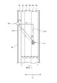
- FIG. 2 is a diagram illustrating a relationship among a driving lane, a vehicle, and a road sign.
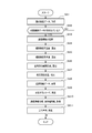
- FIG. 3 is a flowchart showing the operation of the in-vehicle navigation device.
- FIG. 4 is a diagram illustrating an example of captured image data.
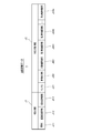
- FIG. 5 is a diagram illustrating a data structure of road information data.
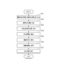
- FIG. 6 is a flowchart showing the operation of the in-vehicle navigation device according to the second embodiment.
- FIG. 7 is a diagram illustrating a relationship among a driving lane, a vehicle, and a road sign.
- FIG. 1 is a block diagram showing a functional configuration of the in-vehicle navigation device according to the first embodiment.
- FIG. 2 is a diagram illustrating a relationship among a driving lane, a vehicle, and a road sign.
- FIG. 3 is a
- FIG. 8 is a flowchart showing the operation of the in-vehicle navigation device according to the third embodiment.
- FIG. 9 is a diagram illustrating a relationship between a driving lane, a vehicle, and a road sign.
- FIG. 10 is a diagram illustrating a configuration of a vehicle position detection system according to the fourth embodiment.
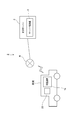
- FIG. 1 is a block diagram showing a functional configuration of an in-vehicle navigation device 1 (information processing device) according to the first embodiment.
- the in-vehicle navigation device 1 is a device mounted on a vehicle, and displays a map for displaying the current position of the vehicle on the displayed map by displaying a map for displaying the vehicle position detection function for detecting the current position of the vehicle.
- a route search function that searches for a route to the destination, and a route display that displays a map, displays a route to the destination on the map, and guides the route to the destination It has a function.
- a vehicle equipped with the in-vehicle navigation device 1 is expressed as “own vehicle”.
- the in-vehicle navigation device 1 includes a control unit 10, a touch panel 11, a storage unit 12, a GPS unit 13, a relative orientation detection unit 14, an interface 15, and a vehicle speed acquisition unit 16. Prepare.
- the control unit 10 includes a CPU, a ROM, a RAM, other peripheral circuits, and the like, and controls each unit of the in-vehicle navigation device 1.
- the CPU 10 controls each unit of the in-vehicle navigation device 1 in cooperation with hardware and software such that the CPU reads and executes a control program stored in the ROM.
- the touch panel 11 includes a display panel 111 and a touch sensor 112.
- the display panel 111 includes a display device such as a liquid crystal display panel or an organic EL panel, and displays various images according to the control of the control unit 10.
- the touch sensor 112 is disposed so as to overlap the display panel 111, detects a user's touch operation, and outputs a signal indicating the touch operation to the control unit 10. Based on the signal input from the touch sensor 112, the control unit 10 executes a process corresponding to the user's touch operation.
- the storage unit 12 includes a nonvolatile memory and stores various data.
- the storage unit 12 stores map data 121.
- the map data 121 includes parcel data.
- Parcel data is data used in the above-described map display and route guidance, road drawing data related to the drawing of road shapes, background drawing data related to drawing of backgrounds such as topography, character strings such as administrative divisions Drawing data relating to the display of the map, such as character string drawing data relating to the drawing.
- the road drawing data includes node information having information on nodes corresponding to connection points in a road network such as intersections, and link information having information on links corresponding to roads formed between the nodes, It also contains information necessary for route guidance.
- the map data 121 includes region data.
- Region data is data used in the route search described above, and corresponds to node information having information on nodes corresponding to connection points in a road network such as intersections and roads formed between nodes. It includes information necessary for route search, such as link information having information about links.
- the map data 121 includes road information data 1211. The road information data 1211 will be described later.
- the GPS unit 13 receives GPS radio waves from GPS satellites via a GPS antenna (not shown), and acquires the current position and traveling direction of the host vehicle from the GPS signals superimposed on the GPS radio waves by calculation.
- the GPS unit 13 outputs the acquisition result to the control unit 10.
- the relative orientation detection unit 14 includes a gyro sensor and an acceleration sensor.
- the gyro sensor is constituted by, for example, a vibrating gyroscope and detects a relative direction (for example, a turning amount in the yaw axis direction) of the host vehicle.
- the acceleration sensor detects acceleration acting on the host vehicle (for example, tilt of the host vehicle with respect to the traveling direction).
- the relative orientation detection unit 14 outputs the detection results of the gyro sensor and the acceleration sensor to the control unit 10.
- the vehicle speed acquisition unit 16 is connected to, for example, a sensor that detects a vehicle speed pulse, detects the vehicle speed of the host vehicle based on the vehicle speed pulse input from the sensor, and communicates with, for example, an ECU (Engine ControltorUnit).
- the vehicle speed of the host vehicle is detected by acquiring information about the vehicle speed from the ECU.
- the vehicle speed acquisition unit 16 outputs the detection result to the control unit 10.
- the control unit 10 detects the vehicle speed of the host vehicle based on the input from the vehicle speed acquisition unit 16.
- the control unit 10 When detecting the position of the host vehicle, the control unit 10 detects the state of the host vehicle such as the vehicle speed detected based on the input from the GPS unit 13 and the relative bearing detection unit 14, the input from the vehicle speed acquisition unit 16, and Then, the current position of the host vehicle is estimated based on the map data 121, and the current position estimated by a method to be described later is appropriately corrected to detect the current position of the host vehicle.
- control unit 10 displays the detected current position of the host vehicle on the map displayed on the touch panel 11.
- control unit 10 searches for a route from the detected current position to the destination set by the user based on the map data 121.
- route guidance the control unit 10 displays the current position of the displayed vehicle on the map while guiding the route while showing the route to the destination on the map.
- the interface 15 is connected to an external device, and communicates with the connected external device according to a predetermined protocol under the control of the control unit 10.
- an in-vehicle camera 20 imaging device
- an external device is connected to the interface 15 as an external device.
- the in-vehicle camera 20 is a stereo camera having two photographing units that photograph the front of the host vehicle.
- the lens mechanisms of the two photographing units are arranged inside the windshield of the host vehicle and spaced apart in the left-right direction, which is a direction orthogonal to the front-rear direction of the host vehicle.
- Each of the two photographing units performs photographing in synchronization with a predetermined cycle.
- the in-vehicle camera 20 generates two captured image data based on the imaging results of the two imaging units, and outputs the generated two captured image data to the control unit 10 via the interface 15.
- the vehicle-mounted navigation apparatus 1 which concerns on this embodiment has a function which performs the own vehicle position detection which detects the present position of the own vehicle. And about the own vehicle position detection, there is a need to detect the current position of the own vehicle on the traveling road with the highest possible accuracy. In particular, with regard to detecting the position of the host vehicle, there is a need to detect which lane the host vehicle is traveling among the plurality of lanes with as high accuracy as possible when the running road has a plurality of lanes. By detecting the lane in which the host vehicle is traveling (hereinafter referred to as “traveling lane”) with high accuracy, the user can be more accurately notified of the lane in which the host vehicle is traveling when displaying a map. In route guidance, it is possible to accurately notify a change in lane for smoothly traveling the searched route, and the convenience for the user is improved. Based on the above, the vehicle-mounted navigation device 1 detects the lane in which the host vehicle is traveling by the following method.
- FIG. 2 shows a road used to detect the position of the host vehicle in a process P1, which is the current position of the host vehicle, and the current position of the host vehicle when the host vehicle is traveling in a predetermined travel lane. It is a figure which shows an example of the relationship with the position P2 which is the position of a sign (hereinafter, simply referred to as “road sign”).
- FIG. 3 is a flowchart showing the operation of the in-vehicle navigation device 1 when detecting the lane in which the host vehicle is traveling.
- the shape of the travel lane is the same as the travel lane illustrated in FIG. 2, and the travel lane, the current position of the host vehicle, and the road sign It is assumed that the relationship with the position conforms to the relationship illustrated in FIG. That is, it is assumed that the travel lane has a plurality of lanes (in the example of FIG. 2, five lanes of the first lane S1 to the fifth lane S5). Further, the travel lane is not bent from the current position of the host vehicle (position P1 in the example of FIG. 2) to at least the position of the road sign (position P2 in the example of FIG. 2) in the traveling direction. It is assumed that the number of lanes does not change and the width of each lane does not change substantially.
- the leftmost lane in the traveling direction (the first lane S1 in the example of FIG. 2) has a roadside zone (in the example of FIG. 2) along the lane. It is assumed that the roadside band R1) extends.
- the position of the road sign (position P2 in the example of FIG. 2) is diagonally left frontward in the traveling direction from the position of the own vehicle (position P1 in the example of FIG. 2), and is mounted on the own vehicle. It is assumed that the position can be taken by the in-vehicle camera 20.
- the direction intersecting with the traveling direction of the host vehicle is referred to as “right angle direction” (in the example of FIG. 2, the right angle direction Y1).
- the control unit 10 of the in-vehicle navigation device 1 acquires captured image data output from the in-vehicle camera 20 (step SA1).
- the in-vehicle camera 20 captures the front of the host vehicle at a predetermined cycle in synchronization with the two capturing units, and outputs captured image data based on the capturing result to the control unit 10. Therefore, the control unit 10 executes the process of step SA1 in a cycle corresponding to the cycle in which the in-vehicle camera 20 outputs the captured image data, and triggers the execution of the process of step SA1 (acquisition of captured image data). The following processing is executed.
- step SA2 the control unit 10 analyzes the captured image data acquired in step SA1 and adds a road sign (hereinafter referred to as “maximum speed road sign”) indicating the maximum speed (restricted speed, regulated speed) in the captured image data. It is determined whether or not target image data that is image data of the image is included (step SA2).
- step SA2 the process of step SA2 will be described in detail. Note that the control unit 10 executes the process of step SA2 using any one of the captured image data input in synchronization with the two stereo cameras.
- FIG. 4 is a diagram schematically illustrating an example of photographed image data in a mode suitable for explanation.
- the captured image data includes dots having information relating to colors (for example, information representing the color components of each RGB color by gradation values of a predetermined gradation) in a dot matrix corresponding to a predetermined resolution. It is the arranged image data.
- the map data 121 includes image data (hereinafter referred to as “template image data”) used as a template in pattern matching for each of the maximum speed road signs for each maximum speed.
- the template image data corresponds to “image data corresponding to the stored target image data”.
- the control unit 10 performs pattern matching using the template image data included in the map data 121, and determines whether or not the captured image data includes target image data.
- the area A1 is image data of an image of a maximum speed road sign indicating that the maximum speed is 50 km / h, and the image data corresponding to the area A1 corresponds to target image data. Therefore, when acquiring the captured image data of FIG.
- the control unit 10 uses the template image data related to the template of the image of the maximum speed road sign indicating that the maximum speed is 50 km / h in step SA2. Based on the pattern matching, it is determined that the target image data is included in the captured image data.
- step SA2 in order to improve the accuracy of determining whether or not the target image data is included in the captured image data and the accuracy of calculating the distance between the marked vehicles described later, the controller 10 captures the captured image data.
- the size of the target image data included in the image data is equal to or larger than a predetermined threshold, it may be determined that the target image data is included in the captured image data.
- the method for determining whether or not the target image data is included in the captured image data is not limited to the method using pattern matching, and any method may be used.
- step SA2 If it is determined in step SA2 that the target image data is not included in the captured image data (step SA2: NO), the control unit 10 ends the process.
- step SA2 When it is determined in step SA2 that the target image data is included in the captured image data (step SA2: YES), the control unit 10 captures a captured road sign (maximum speed road sign) based on the target image data. Is recognized (step SA3).
- a captured road sign maximum speed road sign
- the control unit 10 analyzes the target image data and acquires the type of road sign corresponding to the target image data.
- the control unit 10 specifies a character string or a figure included in a road sign corresponding to the target image data by a method such as pattern matching.
- the map data 121 includes information for associating a character string or a figure included in the road sign with the type of road sign for each type of road sign. Based on the information, the control unit 10 acquires the specified character string and the type of road sign corresponding to the figure.
- the method for identifying the type of road sign is not limited to a method based on a character string or a graphic included in the road sign, and any method may be used.
- the method of specifying the type of road sign may be a method of specifying the type of road sign reflecting the shape, color, etc. of the road sign.
- the control unit 10 sets the distance between the road sign corresponding to the target image data and the own vehicle (hereinafter referred to as “the distance between the marked vehicles. In the example of FIG. 2, the distance A between the marked vehicles)”. calculate.
- the control unit 10 calculates the distance between the marked vehicles by the existing image processing using the difference (parallax) of the target image data in the two captured image data of the two imaging units input from the in-vehicle camera 20. To do.
- the method for calculating the distance between the marked vehicles is not limited to the exemplified method, and any method may be used.
- the control unit 10 may calculate the distance between the marked vehicles by a predetermined means based on the size of the target image data in the captured image data.
- step SA5 the control unit 10 makes a virtual straight line extending in the traveling direction of the host vehicle (virtual straight line KT1 in the example of FIG. 2) and a virtual straight line connecting the host vehicle and the road sign (in the example of FIG. 2).
- a virtual straight line KT2 (hereinafter referred to as “an angle between the marked vehicles.
- an angle ⁇ ) is calculated.
- the control unit 10 determines the distance between the marked vehicles calculated in step SA4, the position of the target image data in the two captured image data of the two imaging units input from the in-vehicle camera 20, and the boundary of the lane in the captured image data.
- the angle between the marked vehicles is calculated by the existing image processing based on the direction of the white line indicating. Note that the method for calculating the angle between the marked vehicles is not limited to the exemplified method, and any method may be used.
- step SA6 the control unit 10 performs a perpendicular direction (in FIG. 4) between the current position of the host vehicle (position P1 in the example of FIG. 2) and the position of the road sign (position P2 in the example of FIG. 2).
- a distance in the right angle direction Y1) (hereinafter referred to as “right angle direction separation distance”.
- the right angle direction separation distance B) is calculated.
- the control unit 10 calculates the perpendicular separation distance by the following formula M1.
- the control unit 10 detects the current position of the host vehicle based on inputs from the GPS unit 13, the relative direction detection unit 14, and the vehicle speed acquisition unit 16 (step SA7).
- the current position of the host vehicle detected based on inputs from the GPS unit 13 and the relative direction detection unit 14 is expressed as “estimated current position”. Since the estimated current position is calculated using the input from the GPS unit 13, an error derived from GPS may occur, and it is not appropriate to detect the traveling lane based on the estimated current position.
- the estimated current position represents the current position of the host vehicle with longitude and latitude.
- the control unit 10 refers to the road information data 1211 (step SA8).
- the road information data 1211 is a database having a record for each of the road signs (road signs managed by the map data 121) displayed on the map based on the map data 121.
- FIG. 5 is a diagram showing the data structure of one record of the road information data 1211. As shown in FIG. 5, one record of the road information data 1211 includes sign information J1 and corresponding road information J2.
- the sign information J1 is information related to the road sign, and is represented by a sign ID J11 for uniquely identifying the road sign, a sign type information J12 indicating the type of the road sign, and a position (longitude and latitude) of the road sign. Label position information J13 indicating the position).
- Corresponding road information J2 is information relating to a road on which a road sign is provided.
- the road provided with the road sign means a road on one side where traveling according to the rules indicated by the road sign is required.
- Corresponding road information J2 includes road link IDJ21 (identification information allocated for each link in the above-described region data or parcel data link information), lane number information J22 indicating the number of lanes of the road, and road signs.
- Road separation information J23 indicating a separation distance between the left end of the leftmost lane in the traveling direction and the position of the road sign (hereinafter referred to as a “sign road separation distance”);
- Corresponding road information J2 includes first lane width information J241 to nth lane width information J24n indicating the width of the lane for each of n (where n is an integer equal to or greater than “1”) lanes on the road.
- n lanes are expressed as a first lane, a second lane,..., An nth lane in order from the leftmost lane in the traveling direction.
- the road separation information J23 corresponds to “information about the separation distance between the object and the road”.
- step SA9 the control unit 10 specifies a road sign record corresponding to the target image data from the records of the road information data 1211.
- step SA9 the process of step SA9 will be described in detail.
- step SA9 the control unit 10 records that the position indicated by the sign position information J13 in the road information data 1211 and the estimated current position detected in step SA7 have a predetermined relationship among the records included in the road information data 1211.
- the position indicated by the sign position information J13 in the road information data 1211 and the estimated current position detected in step SA7 have a predetermined relationship
- the position indicated by the sign position information J13 is a vehicle-mounted camera starting from the estimated current position. It means being within 20 shooting ranges.
- the control unit 10 identifies the extracted record as a road sign record corresponding to the target image data. On the other hand, there may be a case where there are a plurality of records to be extracted.
- the control unit 10 selects a record in which the type of road sign indicated by the sign type information J12 matches the type of road sign corresponding to the target image data acquired in step SA3 among the plurality of extracted records. It is specified as a road sign record corresponding to the image data.
- the same kind of road signs are arranged apart from each other by a predetermined distance or more. Therefore, by identifying the corresponding record by the above method, the road sign record corresponding to the target image data can be appropriately identified.
- step SA10 the control unit 10 acquires the road separation information J23 and the first lane width information J241 to the nth lane width information J24n based on the record specified in step SA9.
- control unit 10 determines whether the host vehicle is based on the separation distance in the perpendicular direction calculated in step SA6, the road separation information J23 acquired in step SA10, and the first lane width information J241 to the nth lane width information J24n.
- a traveling lane (traveling lane) is specified (step SA11).
- the process of step SA11 will be described in detail.
- the lane in which the host vehicle is traveling can be specified by the relationship between the separation distance in the perpendicular direction, the separation distance of the sign road, and the width of each lane that the road has. That is, the separation distance in the perpendicular direction, the separation distance of the sign road, and the widths of the first lane to the nth lane of the road (travel lane) have the following relationship.
- “Signal road separation distance + width of first lane + ... + (m-1) lane width ⁇ right-angle direction separation distance ⁇ sign road separation distance + first lane width + ... + m-th lane Width (where m is an integer greater than or equal to" 1 ").
- the lane (traveling lane) in which the host vehicle is traveling is the mth lane.
- the perpendicular distance C, the sign road separation distance H1, and the widths L1 to L5 of the first lane S1 to the fifth lane S5 of the road (travel lane) are as follows: It is in. “Signal road separation distance H1 + width L1 + width L2 ⁇ right-angle direction separation distance C ⁇ sign road separation distance H1 + width L1 + width L2 + width L3”.
- the lane in which the host vehicle is traveling is the third lane S3.
- step SA11 the control unit 10 determines the lane (travel) in which the host vehicle is traveling based on the relationship between the separation distance in the perpendicular direction, the separation distance between the sign road, and the width of each lane that the road has. Lane).
- the control unit 10 calculates the angle between the marked vehicles, the distance between the marked vehicles, and the separation distance in the perpendicular direction. Then, if the angle between the marked vehicles and the distance between the marked vehicles are determined, the position of the own vehicle with respect to the road sign is determined. Therefore, the angle between the marked vehicles and the distance between the marked vehicles are determined according to “the road sign (object)”. This corresponds to the “relative position of the host vehicle (vehicle)”.
- the right-angle direction separation distance is set to “relative position of the own vehicle (vehicle) with respect to the road sign (object)”. Equivalent to.
- the control unit 10 detects the lane in which the host vehicle travels using the calculated inter-signed vehicle angle, the inter-signed vehicle distance, and the perpendicular separation distance.
- these relative positions can be used in other ways when detecting the host vehicle.
- the control part 10 can detect the relative position of the own vehicle with respect to a road sign based on the angle between labeled vehicles and the distance between labeled vehicles. Therefore, the control unit 10 can detect the position of the host vehicle on the map by acquiring the position of the road sign on the map. And if the estimated current position detected by input from the GPS unit 13 or the like is corrected by the position on the map of the own vehicle detected based on the angle between the marked vehicles and the distance between the marked vehicles, higher accuracy is obtained.
- the position of the host vehicle can be detected.
- an automatic driving system including not only a system related to complete automatic driving but also a system that supports automatic driving in a predetermined case
- the position of the host vehicle can be detected with higher accuracy by using the calculated angle between the marked vehicles, the distance between the marked vehicles, and the separation distance in the perpendicular direction.
- the in-vehicle navigation device 1 acquires captured image data obtained by capturing the outside of the host vehicle (vehicle), and includes road signs in the captured image data.
- target image data that is image data of (predetermined target) is included, based on the target image data, the relative position of the vehicle with respect to the road sign (a combination of the angle between the marked vehicles and the distance between the marked vehicles, or a right angle)
- a control unit 10 that detects the position of the vehicle on the road based on the calculated relative position.
- the relative position of the host vehicle with respect to the road sign is calculated based on the target image data included in the captured image data, and the position of the host vehicle on the road is detected based on the calculated relative position. Therefore, for example, compared to the case where the current position of the vehicle is detected using the accumulated movement amount of the vehicle, the position detection error associated with the increase in the travel distance of the vehicle does not occur, and the vehicle is detected with high accuracy.
- the position on the road can be calculated.
- the vehicle-mounted navigation apparatus 1 includes a storage unit 12 that stores road information data 1211 having road information including information indicating the position of the road sign and information indicating the relationship between the road sign and the road. .
- road information data 1211 having road information including information indicating the position of the road sign and information indicating the relationship between the road sign and the road.
- the control unit 10 can detect the position of the host vehicle on the road with high accuracy based on the calculated relative position using the road information included in the road information data 1211.
- the control unit 10 calculates and calculates, as a relative position, a perpendicular separation distance that is a separation distance between the own vehicle and the road sign in a perpendicular direction (a direction intersecting the traveling direction of the own vehicle). Based on the perpendicular separation distance and the road information data 1211, the position of the host vehicle on the road is calculated. According to this configuration, the control unit 10 uses the road information included in the road information data 1211 to detect the position of the host vehicle on the road with high accuracy based on the calculated perpendicular separation distance.
- the road information of the road information data 1211 includes the first lane width information J241 to the nth lane width information J24n (information on the width of the lane that the road has), and the road separation information J23 (object and object). Information on the distance from the road). Then, the control unit 10 identifies the lane in which the host vehicle is traveling based on the calculated perpendicular separation distance and the road information data 1211. According to this configuration, using the road information included in the road information data 1211, the position of the host vehicle on the road is detected with high accuracy based on the calculated perpendicular separation distance.
- FIG. 6 is a flowchart showing an operation when the in-vehicle navigation device 1 according to the present embodiment detects a lane in which the host vehicle is traveling.
- FIG. 7 is a diagram illustrating the relationship among the travel lane, the position of the road sign, and the position of the host vehicle in order to explain the processing of the in-vehicle navigation device 1 according to the present embodiment.
- the in-vehicle device executes different processes for the processes of Step SA4 to Step SA6 among the processes described using the flowchart of FIG. 3 in the first embodiment. Based on this, in the flowchart of FIG. 6, steps in which the same processing as that in FIG. 3 is performed are assigned the same reference numerals and description thereof is omitted. In the following, the process of steps SB1 to SB5 performed in place of the process of steps SA4 to SA6 in FIG. 3 will be described.
- step SB ⁇ b> 1 the control unit 10 calculates the angle between the marked vehicles by a method similar to the method described in the first embodiment.
- the position of the own vehicle at the timing of executing the process of step SB1 is the position Q1
- the position of the road sign is the position Q2
- the control unit 10 The angle ⁇ 1 is calculated as the angle.
- step SB2 the control unit 10 monitors whether or not the host vehicle has traveled a predetermined distance or more from the timing at which the process of step SB1 is executed (step SB2).
- the detection that the vehicle has traveled over a certain distance in step SB2 does not need to be a strict detection. For example, if there is a high possibility that the vehicle has traveled over a certain distance due to the relationship between the vehicle speed and the travel time, the vehicle travels a certain distance. As described above, it may be determined that the vehicle has traveled.
- step SB3 the second inter-vehicle angle is calculated based on the position Q3) (step SB3).
- the angle between the second marked vehicles is a virtual straight line extending in the traveling direction of the host vehicle (virtual straight line KT3 in the example of FIG. 7), and a second current position of the host vehicle (position Q3 in the example of FIG. 7). This is an angle with a virtual straight line (virtual straight line KT4 in the example of FIG.
- step SB3 the control unit 10 calculates the second labeled vehicle angle in the same manner as the method for calculating the labeled vehicle angle described in the first embodiment.
- the control unit 10 determines the position of the host vehicle at the timing when the process of step SB1 is executed (position Q1 in the example of FIG. 7) and the position of the host vehicle at the timing when the process of step SB3 is executed (see FIG. In the example of FIG. 7, the distance (hereinafter referred to as “vehicle travel distance”. In the example of FIG. 7, the vehicle travel distance E) is calculated (step SB4).
- the control unit 10 is based on the input from the GPS unit 13 and the relative bearing detection unit 14, and the estimated current position of the host vehicle at the time when the process of step SB1 is executed, and the step SB3.
- the estimated current position of the host vehicle at the time when the process is executed is detected, and the vehicle travel distance is calculated by appropriately correcting the vehicle speed and the like during travel.
- the control unit 10 includes an image of a predetermined object (may be a road sign) in the captured image data based on the shooting performed by the in-vehicle camera 20 at the timing when the process of step SB1 is executed, and step SB3.
- the vehicle travel distance is calculated based on the mode of change of the image of the predetermined object in the photographed image data based on the photographing performed by the in-vehicle camera 20 at the timing when the above process is executed.
- the method for calculating the vehicle travel distance is not limited to the exemplified method, and any method may be used.
- control unit 10 determines the angle between the marked vehicles calculated in Step SB1 (the angle ⁇ 1 in the example of FIG. 7), the second angle between the marked vehicles calculated in the step SB3 (the angle ⁇ 2 in the example of FIG. 7), and Based on the vehicle travel distance calculated in step SB4 (vehicle travel distance E in the example of FIG. 7), a perpendicular separation distance (in the example of FIG. 7, perpendicular separation distance C) is calculated (step SB5).
- a second current position position Q3 in the example of FIG. 7
- a virtual straight line virtual straight line KT3 in the example of FIG. 7
- a road that passes through the second current position and extends in the traveling direction of the host vehicle.
- the distance from the intersection of a virtual straight line (virtual straight line KT5 in the example of FIG. 7) that passes through the position of the sign (position Q2 in the example of FIG. 7) and extends in the right-angle direction is the “corresponding distance” (example of FIG. 7). Then, if the corresponding distance x.), The following equation holds.
- tan ⁇ 1 right-angle direction separation distance C / (vehicle travel distance E + corresponding distance x)
- tan ⁇ 2 separation distance C in the right-angle direction / corresponding distance x
- the perpendicular distance C can be calculated by the following equation M4 ′.
- Right-angle direction separation distance C (vehicle travel distance E ⁇ tan ⁇ 1 ⁇ tan ⁇ 2) / (tan ⁇ 2 ⁇ tan ⁇ 1)
- Step SB5 the control unit 10 calculates the perpendicular separation distance using the above-described equation M4.
- the control unit 10 of the in-vehicle navigation device 1 detects the position of the host vehicle (the lane in which the vehicle is traveling) has been described. If the processing described in the present embodiment is performed, the position of the host vehicle can be detected with higher accuracy, as in the first embodiment.
- the calculation of the angle (the angle between the marked vehicles and the angle between the second marked vehicles) with the current position of the own vehicle as the apex is performed twice.
- the configuration may be such that the relative position (separation distance in the perpendicular direction) of the host vehicle with respect to the road sign is calculated by a method corresponding to the above-described method based on the calculated and executed angles three or more times.
- the relative position can be calculated with higher accuracy.
- the in-vehicle camera 20 captures the front of the host vehicle, and the control unit 10 calculates the relative position of the host vehicle with respect to the road sign based on the captured image data based on the capturing result in front of the host vehicle. did.
- the control unit 10 is based on the side of the host vehicle or the result of photographing the rear side by the method described above. Based on the captured image data, it is possible to calculate the relative position of the vehicle with respect to the road sign.
- FIG. 8 is a flowchart showing the operation of the in-vehicle navigation device 1 according to this embodiment.
- FIG. 9 shows the position of a road sign used for detecting the travel lane, the current position of the host vehicle Z1, and the position of the host vehicle when the host vehicle is traveling in a predetermined travel lane. It is a figure which shows an example of the relationship with a certain position Z2.
- the in-vehicle navigation device 1 executes the process of the flowchart shown in FIG. 8 in the following case. That is, when the captured image data includes target image data related to the road sign image, the control unit 10 of the in-vehicle navigation device 1 uses a predetermined means to start from the current position of the host vehicle to the road sign. To determine whether the road is bent. For example, the control unit 10 acquires link information of a road (travel lane) on which the host vehicle travels, and based on the relationship between the link information, the position of the host vehicle, and the position of the road sign, It is determined whether the road is bent between the position and the road sign. The method for determining whether the road is bent is not limited to the exemplified method, and any method may be used. When the control unit 10 determines that the road is bent between the current position of the host vehicle and the road sign, the control unit 10 performs the process of the flowchart of FIG.
- control unit 10 is executing processing corresponding to step SA1 and step SA3 of the flowchart of FIG.
- the control unit 10 of the in-vehicle navigation device 1 is a method similar to the method described in the first embodiment, and based on the target image data related to the road sign image included in the captured image data.
- a distance between the marked vehicles in the example of FIG. 9, a distance F between the marked vehicles
- an angle between the marked vehicles angle ⁇ 3 in the example of FIG. 9 are calculated (step SC1).
- the control unit 10 refers to the road information data 1211 and identifies a road sign record corresponding to the aspect image data in the same method as described in the first embodiment, and the identified record has
- the marker position information J13 is acquired (step SC2).
- the sign position information J13 is the position of the road sign (position expressed by longitude and latitude.
- the coordinates based on the map data 121 may be coordinates in a predetermined coordinate system). It is information which shows.
- the control unit 10 determines the position of the road sign (position Z2 in the example of FIG. 9) indicated by the sign position information J13 acquired in step SC2 and the distance between the marked vehicles calculated in step SC1 (in the example of FIG. 9, Based on the distance between the marked vehicles F.) and the angle between the marked vehicles (in the example of FIG. 9, the angle ⁇ 3), the current position of the host vehicle (the position Z1 in the example of FIG. 9) is calculated (step SC3). .
- the distance between the marked vehicles and the angle between the marked vehicles the relative position of the own vehicle with respect to the road sign is determined. Therefore, the current position of the own vehicle is determined by determining the position of the road sign.
- the control unit 10 refers to the map data 121 and acquires information about the center line of the road (travel lane) on which the host vehicle travels (hereinafter referred to as “center line information”) (step SC4).
- the center line of the road is a line that follows the center in the direction perpendicular to the entire road width including the traveling lane with which the traveling direction is opposite on the roadway.
- Line TS In the example of FIG. Line TS.
- the center line on the map is managed as a collection of straight lines (hereinafter referred to as “unit straight lines”) along the center line.
- the center line TS is managed as a unit straight line TS1 and a unit straight line TS2.
- the map data 121 includes unit line information including a position on the map at one end and a position on the map at the other end for each unit line.
- the control unit 10 acquires unit straight line information of a unit straight line (in the example of FIG. 9, a unit straight line TS1) located on the side of the position of the host vehicle as center line information.
- control unit 10 determines the current position of the own vehicle, the perpendicular line, and the unit straight line when the perpendicular line is dropped from the current position of the own vehicle with respect to the unit straight line indicated by the unit straight line information acquired in step SC4.
- the length with the intersection (length N2 in the example of FIG. 9) is calculated (step SC5).
- control unit 10 refers to the road information data 1211 and acquires the first lane width information J241 to the nth lane width information J24n of the road that is running (step SC6).
- the control unit 10 determines the center line information (unit straight line information) acquired in step SC4, the length of the perpendicular calculated in step SC5, and the first lane width information J241 to the nth lane width information acquired in step SC6. Based on J24n, the lane in which the host vehicle is traveling is specified (step SC7).
- the lane in which the host vehicle is traveling is specified (step SC7).
- the width of each lane provided on the road and the distance between the center line and the current position of the host vehicle are determined, the lane in which the host vehicle is positioned is determined.
- step SC7 the control unit 10 calculates the position of the intersection of the perpendicular and the center line on the map, and based on the relationship between the position, the length of the perpendicular, and the width of the lane. Identify the lane in which the vehicle is traveling.
- control unit 10 of the in-vehicle navigation device 1 detects the position of the host vehicle (the lane in which the vehicle is traveling) has been described above. If the process described in this embodiment is performed, the position of the host vehicle can be detected with higher accuracy, as in the first embodiment and the second embodiment.
- FIG. 10 is a diagram illustrating a vehicle position detection system 2 according to the fourth embodiment.
- the device mounted on the vehicle executes the process related to the detection of the current location of the host vehicle.
- the processing is executed by the control server 3 that can communicate with the device mounted on the vehicle via the network N.
- the control server 3 functions as an “information processing apparatus”.
- the vehicle-mounted device 1 b As shown in FIG. 10, the vehicle-mounted device 1 b according to the present embodiment is mounted on the vehicle.
- the in-vehicle camera 20 is connected to the in-vehicle device 1b according to the present embodiment.
- the in-vehicle device 1b is communicably connected to the control server 3 via a network N configured including the Internet.
- the in-vehicle device 1b may have a function of accessing the network N so that the in-vehicle device 1b directly accesses the network N.
- a terminal having a function of accessing the in-vehicle device 1b and the network N (for example, a vehicle occupant It may be configured such that the in-vehicle device 1b accesses the network N via a terminal by connecting to a mobile phone) possessed by short-range wireless communication, wired communication, or other communication method.
- the in-vehicle device 1b has a function of transmitting captured image data input from the in-vehicle camera 20 to the in-vehicle navigation device 1 via the network N.
- the control server 5 includes a CPU, a ROM, a RAM, other peripheral circuits, and the like.
- the server control unit 6 controls each unit of the control server 5 by cooperation of hardware and software such as reading and executing a program. Is provided.
- the server control unit 6 functions as a “control unit”.
- the server control unit 6 receives the captured image data from the in-vehicle device 1b, performs a process corresponding to the flowchart of FIG. 3, FIG. 6, or FIG. Detect the relative position of the vehicle.
- the control server 5 stores the information necessary for the processing related to the detection (for example, the information corresponding to the estimated current position described above or the information included in the road information data 1211), or as necessary. Obtained from the in-vehicle device 1b at an appropriate timing.
- the server control unit 6 appropriately notifies the in-vehicle device 1b of the detection result of information indicating the relative position of the host vehicle with respect to the detected road sign.
- the in-vehicle device 1b executes a corresponding process based on the notification from the control server 5.
- the vehicle-mounted apparatus 1b mounted in the vehicle can acquire the relative position of the own vehicle with respect to a road sign, and acquired relative position.
- the corresponding processing can be executed based on the above.
- the in-vehicle navigation device 1 and the control server 5 detect the relative position of the host vehicle with respect to a road sign as an object.
- the object is not limited to a road sign and may be anything as long as it can be photographed by the in-vehicle camera 20.
- the object may be a signal, a building, a signboard, or the like.
- the road sign has a characteristic that the position where it is provided is determined to some extent in relation to the road, a characteristic that it is managed by the map data 121, and a characteristic that the types are limited and there is a standard of shape for each type. Yes, it is suitable as an object.
- FIGS. 1 and 10 are schematic diagrams showing the functional configurations of the in-vehicle navigation device 1 and the control server 5 classified according to main processing contents in order to facilitate understanding of the present invention.
- the configurations of these devices can be classified into more components depending on the processing contents. Moreover, it can also classify
- the present invention is not limited by the way of dividing the processing unit or the name.
- the processing of each device can be divided into more processing units according to the processing content. Moreover, it can also divide
- the in-vehicle navigation device 1 is configured to acquire captured image data from the in-vehicle camera 20 that is an external device, but the in-vehicle navigation device 1 may have a configuration having an imaging function.
- SYMBOLS 1 Car-mounted navigation apparatus (information processing apparatus), 5 ... Control server (information processing apparatus), 6 ... Server control part (control part), 10 ... Control part, 12 ... Memory
Landscapes
- Engineering & Computer Science (AREA)
- Radar, Positioning & Navigation (AREA)
- Remote Sensing (AREA)
- Physics & Mathematics (AREA)
- General Physics & Mathematics (AREA)
- Automation & Control Theory (AREA)
- Computer Vision & Pattern Recognition (AREA)
- Theoretical Computer Science (AREA)
- Computer Networks & Wireless Communication (AREA)
- Multimedia (AREA)
- Navigation (AREA)
- Traffic Control Systems (AREA)
- Image Processing (AREA)
- Image Analysis (AREA)
Abstract
L'objectif de l'invention est de calculer la position d'un véhicule sur une route avec une précision accrue. Un dispositif de navigation monté sur véhicule (1) est muni d'une unité de commande (10) qui acquiert des données d'image capturée obtenues par la capture d'images à l'extérieur d'un véhicule. Si les données d'image capturée comprennent des données d'image cible, qui sont des données d'image d'un panneau de signalisation, l'unité de commande (10) calcule une position relative du véhicule par rapport au panneau de signalisation, en fonction des données d'image cible, et détecte la position du véhicule sur la route en fonction de la position relative calculée.
Priority Applications (2)
| Application Number | Priority Date | Filing Date | Title |
|---|---|---|---|
| US15/556,116 US20180045516A1 (en) | 2015-03-19 | 2016-03-17 | Information processing device and vehicle position detecting method |
| EP16765066.2A EP3279611A4 (fr) | 2015-03-19 | 2016-03-17 | Dispositif de traitement d'informations, et procédé de détection de position de véhicule |
Applications Claiming Priority (2)
| Application Number | Priority Date | Filing Date | Title |
|---|---|---|---|
| JP2015-056157 | 2015-03-19 | ||
| JP2015056157A JP2016176769A (ja) | 2015-03-19 | 2015-03-19 | 情報処理装置、及び、車両位置検出方法 |
Publications (1)
| Publication Number | Publication Date |
|---|---|
| WO2016148237A1 true WO2016148237A1 (fr) | 2016-09-22 |
Family
ID=56919246
Family Applications (1)
| Application Number | Title | Priority Date | Filing Date |
|---|---|---|---|
| PCT/JP2016/058501 Ceased WO2016148237A1 (fr) | 2015-03-19 | 2016-03-17 | Dispositif de traitement d'informations, et procédé de détection de position de véhicule |
Country Status (4)
| Country | Link |
|---|---|
| US (1) | US20180045516A1 (fr) |
| EP (1) | EP3279611A4 (fr) |
| JP (1) | JP2016176769A (fr) |
| WO (1) | WO2016148237A1 (fr) |
Cited By (4)
| Publication number | Priority date | Publication date | Assignee | Title |
|---|---|---|---|---|
| CN108051836A (zh) * | 2017-11-02 | 2018-05-18 | 中兴通讯股份有限公司 | 一种定位方法、装置、服务器及系统 |
| CN110018503A (zh) * | 2018-01-10 | 2019-07-16 | 上海汽车集团股份有限公司 | 车辆的定位方法及定位系统 |
| CN110287803A (zh) * | 2019-05-29 | 2019-09-27 | 广州小鹏汽车科技有限公司 | 一种轨迹路标的识别方法及系统 |
| JP2021169989A (ja) * | 2020-04-17 | 2021-10-28 | 株式会社Nichijo | 自己位置測定システム、車両、及び、自己位置測定方法 |
Families Citing this family (30)
| Publication number | Priority date | Publication date | Assignee | Title |
|---|---|---|---|---|
| WO2017009923A1 (fr) * | 2015-07-13 | 2017-01-19 | 日産自動車株式会社 | Dispositif et procédé d'estimation d'une position propre |
| JP6602683B2 (ja) * | 2016-02-05 | 2019-11-06 | 株式会社東芝 | 充電装置および位置ずれ検出方法 |
| EP3239660B1 (fr) * | 2016-04-26 | 2019-06-19 | Volvo Car Corporation | Procédé et système permettant d'activer de façon sélective un dispositif utilisateur en mouvement pour utiliser un contenu numérique associé à des entités en avant |
| WO2017199369A1 (fr) * | 2016-05-18 | 2017-11-23 | パイオニア株式会社 | Dispositif de reconnaissance d'objet physique, procédé de reconnaissance d'objet et programme |
| WO2018020588A1 (fr) * | 2016-07-26 | 2018-02-01 | 日産自動車株式会社 | Procédé d'estimation de position automatique et dispositif d'estimation de position automatique |
| KR102406498B1 (ko) * | 2016-12-07 | 2022-06-10 | 현대자동차주식회사 | 차량의 자율주행모드와 운전보조모드 간의 변환방법 |
| KR102695518B1 (ko) * | 2017-01-26 | 2024-08-14 | 삼성전자주식회사 | 차량 경로 가이드 방법 및 장치 |
| DE102017001707A1 (de) * | 2017-02-22 | 2018-08-23 | GM Global Technology Operations LLC (n. d. Ges. d. Staates Delaware) | Benachrichtigung über einen geschätzten Bewegungspfad eines Fahrzeugs |
| JP6733582B2 (ja) * | 2017-03-08 | 2020-08-05 | 株式会社デンソー | 標識認識システム |
| JP7079070B2 (ja) * | 2017-04-27 | 2022-06-01 | 株式会社ゼンリン | 走行支援装置及びプログラム |
| JP6946044B2 (ja) * | 2017-04-27 | 2021-10-06 | 株式会社ゼンリン | 走行支援装置及びプログラム |
| EP3637055A4 (fr) * | 2017-05-19 | 2021-03-03 | Pioneer Corporation | Dispositif de mesure, procédé de mesure et programme |
| JP6838522B2 (ja) * | 2017-08-10 | 2021-03-03 | トヨタ自動車株式会社 | 画像収集システム、画像収集方法、画像収集装置、および記録媒体 |
| JP6941677B2 (ja) * | 2017-08-25 | 2021-09-29 | 日立Astemo株式会社 | 画像認識装置 |
| FR3072182A1 (fr) * | 2018-03-05 | 2019-04-12 | Continental Automotive France | Calculateur, systeme et procede de geolocalisation d'un vehicule |
| US10558872B2 (en) * | 2018-03-23 | 2020-02-11 | Veoneer Us Inc. | Localization by vision |
| CN111936820A (zh) * | 2018-03-30 | 2020-11-13 | 丰田自动车欧洲公司 | 用于调整车辆外部位置信息的系统和方法 |
| JP7025293B2 (ja) * | 2018-07-10 | 2022-02-24 | トヨタ自動車株式会社 | 自車位置推定装置 |
| CN109029458B (zh) * | 2018-07-19 | 2020-06-30 | 东莞信大融合创新研究院 | 一种双目视觉定位的方法 |
| WO2020021596A1 (fr) * | 2018-07-23 | 2020-01-30 | 三菱電機株式会社 | Dispositif d'estimation de position de véhicule et procédé d'estimation de position de véhicule |
| GB201818357D0 (en) * | 2018-11-12 | 2018-12-26 | Forsberg Services Ltd | Locating system |
| US11003190B2 (en) | 2018-12-13 | 2021-05-11 | Here Global B.V. | Methods and systems for determining positional offset associated with a road sign |
| TWI696144B (zh) | 2018-12-19 | 2020-06-11 | 財團法人工業技術研究院 | 影像生成器的訓練方法 |
| CN112149659B (zh) * | 2019-06-27 | 2021-11-09 | 浙江商汤科技开发有限公司 | 定位方法及装置、电子设备和存储介质 |
| CN110727269B (zh) * | 2019-10-09 | 2023-06-23 | 陈浩能 | 车辆控制方法及相关产品 |
| US11125575B2 (en) | 2019-11-20 | 2021-09-21 | Here Global B.V. | Method and apparatus for estimating a location of a vehicle |
| JP2022178701A (ja) * | 2021-05-20 | 2022-12-02 | フォルシアクラリオン・エレクトロニクス株式会社 | ナビゲーション装置 |
| JP7726226B2 (ja) * | 2023-01-27 | 2025-08-20 | トヨタ自動車株式会社 | 情報処理装置 |
| CN116380107B (zh) * | 2023-05-29 | 2023-08-22 | 速度科技股份有限公司 | 一种基于高精地图对车辆进行定位的系统 |
| CN118230001B (zh) * | 2024-03-19 | 2025-09-19 | 华南理工大学 | 一种sdf向量高精地图变化检测方法 |
Citations (6)
| Publication number | Priority date | Publication date | Assignee | Title |
|---|---|---|---|---|
| JPH04163251A (ja) * | 1990-10-29 | 1992-06-08 | Oki Electric Ind Co Ltd | 走行車線認識システム |
| JP2009033743A (ja) * | 2007-07-30 | 2009-02-12 | Delphi Technologies Inc | 物体を認識するための方法 |
| JP2010519550A (ja) * | 2007-02-21 | 2010-06-03 | テレ アトラス ノース アメリカ インコーポレイテッド | 絶対座標及び相対座標を含む車両ナビゲーション及び案内のためのシステム及び方法 |
| US20130261838A1 (en) * | 2012-03-28 | 2013-10-03 | Gentex Corporation | Vehicular imaging system and method for determining roadway width |
| WO2014166532A1 (fr) * | 2013-04-10 | 2014-10-16 | Harman Becker Automotive Systems Gmbh | Système de navigation et procédé de détermination de la position d'un véhicule |
| JP2014203115A (ja) * | 2013-04-01 | 2014-10-27 | パイオニア株式会社 | 検出装置、制御方法、プログラム及び記憶媒体 |
Family Cites Families (7)
| Publication number | Priority date | Publication date | Assignee | Title |
|---|---|---|---|---|
| JP2007232690A (ja) * | 2006-03-03 | 2007-09-13 | Denso Corp | 現在地検出装置、地図表示装置、および現在地検出方法 |
| JP2011013039A (ja) * | 2009-06-30 | 2011-01-20 | Clarion Co Ltd | 車線判定装置及びナビゲーションシステム |
| EP2491344B1 (fr) * | 2009-10-22 | 2016-11-30 | TomTom Global Content B.V. | Système et procédé de navigation pour véhicule au moyen de décalages latéraux |
| DE102011112404B4 (de) * | 2011-09-03 | 2014-03-20 | Audi Ag | Verfahren zum Bestimmen der Position eines Kraftfahrzeugs |
| EP2950291A4 (fr) * | 2013-01-25 | 2016-10-12 | Toyota Motor Co Ltd | Système de reconnaissance d'environnement routier |
| JP2015003566A (ja) * | 2013-06-19 | 2015-01-08 | トヨタ自動車株式会社 | 逸脱防止装置 |
| WO2015116950A1 (fr) * | 2014-01-30 | 2015-08-06 | Anna Clarke | Systèmes et procédés de reconnaissance de fin de voie |
-
2015
- 2015-03-19 JP JP2015056157A patent/JP2016176769A/ja active Pending
-
2016
- 2016-03-17 US US15/556,116 patent/US20180045516A1/en not_active Abandoned
- 2016-03-17 EP EP16765066.2A patent/EP3279611A4/fr not_active Withdrawn
- 2016-03-17 WO PCT/JP2016/058501 patent/WO2016148237A1/fr not_active Ceased
Patent Citations (6)
| Publication number | Priority date | Publication date | Assignee | Title |
|---|---|---|---|---|
| JPH04163251A (ja) * | 1990-10-29 | 1992-06-08 | Oki Electric Ind Co Ltd | 走行車線認識システム |
| JP2010519550A (ja) * | 2007-02-21 | 2010-06-03 | テレ アトラス ノース アメリカ インコーポレイテッド | 絶対座標及び相対座標を含む車両ナビゲーション及び案内のためのシステム及び方法 |
| JP2009033743A (ja) * | 2007-07-30 | 2009-02-12 | Delphi Technologies Inc | 物体を認識するための方法 |
| US20130261838A1 (en) * | 2012-03-28 | 2013-10-03 | Gentex Corporation | Vehicular imaging system and method for determining roadway width |
| JP2014203115A (ja) * | 2013-04-01 | 2014-10-27 | パイオニア株式会社 | 検出装置、制御方法、プログラム及び記憶媒体 |
| WO2014166532A1 (fr) * | 2013-04-10 | 2014-10-16 | Harman Becker Automotive Systems Gmbh | Système de navigation et procédé de détermination de la position d'un véhicule |
Non-Patent Citations (1)
| Title |
|---|
| See also references of EP3279611A4 * |
Cited By (7)
| Publication number | Priority date | Publication date | Assignee | Title |
|---|---|---|---|---|
| CN108051836A (zh) * | 2017-11-02 | 2018-05-18 | 中兴通讯股份有限公司 | 一种定位方法、装置、服务器及系统 |
| CN108051836B (zh) * | 2017-11-02 | 2022-06-10 | 中兴通讯股份有限公司 | 一种定位方法、装置、服务器及系统 |
| US12117541B2 (en) | 2017-11-02 | 2024-10-15 | Zte Corporation | Positioning method and device, and server and system |
| CN110018503A (zh) * | 2018-01-10 | 2019-07-16 | 上海汽车集团股份有限公司 | 车辆的定位方法及定位系统 |
| CN110287803A (zh) * | 2019-05-29 | 2019-09-27 | 广州小鹏汽车科技有限公司 | 一种轨迹路标的识别方法及系统 |
| CN110287803B (zh) * | 2019-05-29 | 2021-07-13 | 广州小鹏自动驾驶科技有限公司 | 一种轨迹路标的识别方法及系统 |
| JP2021169989A (ja) * | 2020-04-17 | 2021-10-28 | 株式会社Nichijo | 自己位置測定システム、車両、及び、自己位置測定方法 |
Also Published As
| Publication number | Publication date |
|---|---|
| EP3279611A1 (fr) | 2018-02-07 |
| JP2016176769A (ja) | 2016-10-06 |
| US20180045516A1 (en) | 2018-02-15 |
| EP3279611A4 (fr) | 2018-11-21 |
Similar Documents
| Publication | Publication Date | Title |
|---|---|---|
| WO2016148237A1 (fr) | Dispositif de traitement d'informations, et procédé de détection de position de véhicule | |
| JP7785858B2 (ja) | 自動運転支援装置、制御方法、プログラム及び記憶媒体 | |
| JP6424761B2 (ja) | 運転支援システム及びセンタ | |
| CN111351502B (zh) | 用于从透视图生成环境的俯视图的方法,装置和计算机程序产品 | |
| JP4847090B2 (ja) | 位置測位装置、および位置測位方法 | |
| CN113748447B (zh) | 幽灵交通拥堵检测和避免 | |
| US8275542B2 (en) | Navigation device, navigation method, and navigation program | |
| US8504293B2 (en) | Travel guiding apparatus for vehicle, travel guiding method for vehicle, and computer-readable storage medium | |
| JP6775188B2 (ja) | ヘッドアップディスプレイ装置および表示制御方法 | |
| JP5058243B2 (ja) | 車両案内装置、車両案内方法、及び車両案内プログラム | |
| EP2598842B1 (fr) | Dispositif, procédé et programme de guidage | |
| JP2010271155A (ja) | 現在位置特定装置とその現在位置特定方法 | |
| JP2008309529A (ja) | ナビゲーション装置、ナビゲーション方法、及びナビゲーション用プログラム | |
| JP2002243469A (ja) | ナビゲーション装置および地図データベース更新システム | |
| US20170323566A1 (en) | Electronic apparatus, guide method, and guide system | |
| CN110998684B (zh) | 图像收集系统、图像收集方法、图像收集装置、记录介质 | |
| WO2015087502A1 (fr) | Dispositif d'autolocalisation de véhicule | |
| JP6875057B2 (ja) | 電子装置、走行レーン検出プログラムおよび走行レーン検出方法 | |
| JP2019100924A (ja) | 車両軌跡補正装置 | |
| JP4936070B2 (ja) | ナビゲーション装置及びナビゲーションプログラム | |
| US11959767B2 (en) | Map information assessment device, storage medium storing computer program for map information assessment, and map information assessment method | |
| JP2013036930A (ja) | ナビゲーション装置およびこれを備えたナビゲーションシステム | |
| JP4953015B2 (ja) | 自車位置認識装置と自車位置認識プログラム、及びこれを用いたナビゲーション装置 | |
| CN115808179B (zh) | 一种交通信息获取方法、装置及存储介质 | |
| JP2011232271A (ja) | ナビゲーション装置、車載センサの精度推定方法、および、プログラム |
Legal Events
| Date | Code | Title | Description |
|---|---|---|---|
| 121 | Ep: the epo has been informed by wipo that ep was designated in this application |
Ref document number: 16765066 Country of ref document: EP Kind code of ref document: A1 |
|
| WWE | Wipo information: entry into national phase |
Ref document number: 15556116 Country of ref document: US |
|
| NENP | Non-entry into the national phase |
Ref country code: DE |
|
| REEP | Request for entry into the european phase |
Ref document number: 2016765066 Country of ref document: EP |