WO2016151938A1 - レーザレーダ装置及び走行体 - Google Patents
レーザレーダ装置及び走行体 Download PDFInfo
- Publication number
- WO2016151938A1 WO2016151938A1 PCT/JP2015/082562 JP2015082562W WO2016151938A1 WO 2016151938 A1 WO2016151938 A1 WO 2016151938A1 JP 2015082562 W JP2015082562 W JP 2015082562W WO 2016151938 A1 WO2016151938 A1 WO 2016151938A1
- Authority
- WO
- WIPO (PCT)
- Prior art keywords
- light
- light receiving
- laser
- target area
- radar device
- Prior art date
- Legal status (The legal status is an assumption and is not a legal conclusion. Google has not performed a legal analysis and makes no representation as to the accuracy of the status listed.)
- Ceased
Links
Images


Classifications
-
- G—PHYSICS
- G01—MEASURING; TESTING
- G01S—RADIO DIRECTION-FINDING; RADIO NAVIGATION; DETERMINING DISTANCE OR VELOCITY BY USE OF RADIO WAVES; LOCATING OR PRESENCE-DETECTING BY USE OF THE REFLECTION OR RERADIATION OF RADIO WAVES; ANALOGOUS ARRANGEMENTS USING OTHER WAVES
- G01S17/00—Systems using the reflection or reradiation of electromagnetic waves other than radio waves, e.g. lidar systems
- G01S17/02—Systems using the reflection of electromagnetic waves other than radio waves
- G01S17/06—Systems determining position data of a target
- G01S17/42—Simultaneous measurement of distance and other co-ordinates
-
- B—PERFORMING OPERATIONS; TRANSPORTING
- B61—RAILWAYS
- B61L—GUIDING RAILWAY TRAFFIC; ENSURING THE SAFETY OF RAILWAY TRAFFIC
- B61L15/00—Indicators provided on the vehicle or train for signalling purposes
- B61L15/0081—On-board diagnosis or maintenance
-
- B—PERFORMING OPERATIONS; TRANSPORTING
- B61—RAILWAYS
- B61L—GUIDING RAILWAY TRAFFIC; ENSURING THE SAFETY OF RAILWAY TRAFFIC
- B61L23/00—Control, warning or like safety means along the route or between vehicles or trains
-
- G—PHYSICS
- G01—MEASURING; TESTING
- G01B—MEASURING LENGTH, THICKNESS OR SIMILAR LINEAR DIMENSIONS; MEASURING ANGLES; MEASURING AREAS; MEASURING IRREGULARITIES OF SURFACES OR CONTOURS
- G01B11/00—Measuring arrangements characterised by the use of optical techniques
- G01B11/24—Measuring arrangements characterised by the use of optical techniques for measuring contours or curvatures
-
- G—PHYSICS
- G01—MEASURING; TESTING
- G01C—MEASURING DISTANCES, LEVELS OR BEARINGS; SURVEYING; NAVIGATION; GYROSCOPIC INSTRUMENTS; PHOTOGRAMMETRY OR VIDEOGRAMMETRY
- G01C3/00—Measuring distances in line of sight; Optical rangefinders
- G01C3/02—Details
- G01C3/06—Use of electric means to obtain final indication
-
- G—PHYSICS
- G01—MEASURING; TESTING
- G01S—RADIO DIRECTION-FINDING; RADIO NAVIGATION; DETERMINING DISTANCE OR VELOCITY BY USE OF RADIO WAVES; LOCATING OR PRESENCE-DETECTING BY USE OF THE REFLECTION OR RERADIATION OF RADIO WAVES; ANALOGOUS ARRANGEMENTS USING OTHER WAVES
- G01S17/00—Systems using the reflection or reradiation of electromagnetic waves other than radio waves, e.g. lidar systems
- G01S17/88—Lidar systems specially adapted for specific applications
- G01S17/93—Lidar systems specially adapted for specific applications for anti-collision purposes
- G01S17/931—Lidar systems specially adapted for specific applications for anti-collision purposes of land vehicles
-
- G—PHYSICS
- G01—MEASURING; TESTING
- G01S—RADIO DIRECTION-FINDING; RADIO NAVIGATION; DETERMINING DISTANCE OR VELOCITY BY USE OF RADIO WAVES; LOCATING OR PRESENCE-DETECTING BY USE OF THE REFLECTION OR RERADIATION OF RADIO WAVES; ANALOGOUS ARRANGEMENTS USING OTHER WAVES
- G01S7/00—Details of systems according to groups G01S13/00, G01S15/00, G01S17/00
- G01S7/48—Details of systems according to groups G01S13/00, G01S15/00, G01S17/00 of systems according to group G01S17/00
- G01S7/481—Constructional features, e.g. arrangements of optical elements
- G01S7/4816—Constructional features, e.g. arrangements of optical elements of receivers alone
-
- G—PHYSICS
- G01—MEASURING; TESTING
- G01S—RADIO DIRECTION-FINDING; RADIO NAVIGATION; DETERMINING DISTANCE OR VELOCITY BY USE OF RADIO WAVES; LOCATING OR PRESENCE-DETECTING BY USE OF THE REFLECTION OR RERADIATION OF RADIO WAVES; ANALOGOUS ARRANGEMENTS USING OTHER WAVES
- G01S7/00—Details of systems according to groups G01S13/00, G01S15/00, G01S17/00
- G01S7/48—Details of systems according to groups G01S13/00, G01S15/00, G01S17/00 of systems according to group G01S17/00
- G01S7/481—Constructional features, e.g. arrangements of optical elements
- G01S7/4817—Constructional features, e.g. arrangements of optical elements relating to scanning
-
- G—PHYSICS
- G01—MEASURING; TESTING
- G01S—RADIO DIRECTION-FINDING; RADIO NAVIGATION; DETERMINING DISTANCE OR VELOCITY BY USE OF RADIO WAVES; LOCATING OR PRESENCE-DETECTING BY USE OF THE REFLECTION OR RERADIATION OF RADIO WAVES; ANALOGOUS ARRANGEMENTS USING OTHER WAVES
- G01S7/00—Details of systems according to groups G01S13/00, G01S15/00, G01S17/00
- G01S7/48—Details of systems according to groups G01S13/00, G01S15/00, G01S17/00 of systems according to group G01S17/00
- G01S7/483—Details of pulse systems
- G01S7/486—Receivers
- G01S7/4865—Time delay measurement, e.g. time-of-flight measurement, time of arrival measurement or determining the exact position of a peak
-
- G—PHYSICS
- G02—OPTICS
- G02B—OPTICAL ELEMENTS, SYSTEMS OR APPARATUS
- G02B19/00—Condensers, e.g. light collectors or similar non-imaging optics
- G02B19/0004—Condensers, e.g. light collectors or similar non-imaging optics characterised by the optical means employed
- G02B19/0009—Condensers, e.g. light collectors or similar non-imaging optics characterised by the optical means employed having refractive surfaces only
- G02B19/0014—Condensers, e.g. light collectors or similar non-imaging optics characterised by the optical means employed having refractive surfaces only at least one surface having optical power
-
- G—PHYSICS
- G02—OPTICS
- G02B—OPTICAL ELEMENTS, SYSTEMS OR APPARATUS
- G02B26/00—Optical devices or arrangements for the control of light using movable or deformable optical elements
- G02B26/08—Optical devices or arrangements for the control of light using movable or deformable optical elements for controlling the direction of light
- G02B26/10—Scanning systems
- G02B26/101—Scanning systems with both horizontal and vertical deflecting means, e.g. raster or XY scanners
-
- G—PHYSICS
- G08—SIGNALLING
- G08G—TRAFFIC CONTROL SYSTEMS
- G08G1/00—Traffic control systems for road vehicles
- G08G1/16—Anti-collision systems
-
- G—PHYSICS
- G02—OPTICS
- G02B—OPTICAL ELEMENTS, SYSTEMS OR APPARATUS
- G02B27/00—Optical systems or apparatus not provided for by any of the groups G02B1/00 - G02B26/00, G02B30/00
- G02B27/09—Beam shaping, e.g. changing the cross-sectional area, not otherwise provided for
- G02B27/0938—Using specific optical elements
- G02B27/095—Refractive optical elements
- G02B27/0955—Lenses
Definitions
- the present invention relates to a laser radar device that generates three-dimensional information of a measurement target area by scanning a laser beam, and a traveling body.
- three-dimensional information of the measurement target area is obtained from the distribution of light reception signals obtained by irradiating laser light while scanning the measurement target area and receiving reflected light from an object or the like present in the measurement target area by the light receiving element.
- Laser radar devices are known to generate.
- a scanner is provided on each of the transmitting side of the laser beam and the receiving side of the reflected light, and is adjusted to the mirror angle (transmission angle of the laser beam) of the scanner on the transmitting side during scanning. Reflected light is made to enter the light receiving element by adjusting the mirror angle (light receiving angle of the reflected light) of the scanner on the light receiving side as needed.
- the scanners are provided on both the light transmission side and the light reception side, there is a problem that the size of the entire laser radar apparatus is increased.
- the laser radar device includes a long light receiving element array in which long light receiving elements are arranged in an array in a direction orthogonal to the long direction of the light receiving element, a transimpedance amplifier array for amplifying a received signal, and a transimpedance amplifier array.
- Patent No. 5602225 gazette
- the entire long light receiving element array becomes large. there were.
- an addition circuit for adding the reception signals received by the respective long light receiving elements arranged in an array is required, and there is a problem that the device configuration and the signal processing become complicated.
- the present invention has been made in view of the above, and it is an object of the present invention to provide a laser radar device capable of realizing scanless on the light receiving side with a simple configuration while achieving downsizing of the light receiving element, and a running body. I assume.
- the present invention provides a laser light source, a light transmitting side lens for forming laser light emitted from the laser light source into a point shape, and a laser light formed into a point shape
- a scanner that irradiates while scanning in a first direction of a measurement target area and a second direction orthogonal to the first direction, a light receiving side lens that receives reflected light reflected from the measurement target area, and a light receiving side lens
- a light receiving side optical system for collecting the reflected light received in the first direction and the second direction, and a reflected light collected by the light receiving side optical system are received, and laser light included in the received reflected light
- a light receiving unit that outputs a received signal based on the information processing unit is provided, and an information generating unit that generates three-dimensional information of a measurement target area based on the received signal output from the light receiving unit.
- the light receiving side optical system condenses the reflected light received by the light receiving side lens in the first direction and the second direction, and the reflected light collected by the light receiving side optical system, Since the light receiving portion for outputting a reception signal based on the laser light contained in the received reflected light is provided, the light receiving element of the light receiving portion can be miniaturized, and the entire measurement target area can be used as a sensor field of view of the light receiving element. It can be accommodated and scanless on the light receiving side can be realized with a simple configuration.
- a single light receiving element may be provided. According to this configuration, since the entire area to be measured can be contained in the sensor field of view of a single light receiving element, an addition circuit for adding received signals of the light receiving element is not necessary, and simplification of the circuit configuration can be realized.
- the light receiving side optical system includes a relay lens disposed near or at the back of the image forming position of the light receiving side lens, and a focusing lens for focusing the substantially parallel light flux transmitted from the relay lens toward the light receiving portion. You may have. According to this configuration, the imaging information of the light receiving side lens can be focused on the light receiving section with a simple configuration in which two types of lenses are combined.
- the information generation unit controls the light transmission of the scanner when the laser light is irradiated and the distance information to the measurement target area acquired from the light round trip time from the irradiation of the laser light to the reception by the light reception unit.
- Three-dimensional information of the area to be measured may be generated from each position information of the first direction and the second direction acquired based on the angle. According to this configuration, it is not necessary to acquire spatial position coordinates of the received signal due to the field-of-view scan on the light receiving side, so the load of signal processing for generating three-dimensional information can be reduced.
- the above-described laser radar device may be mounted on a traveling body. According to this configuration, three-dimensional information of the traveling route of the traveling body can be constantly acquired, and driving support of the traveling body can be performed.
- the light receiving side optical system for collecting the reflected light received by the light receiving side lens in the first direction and the second direction and the reflected light collected by the light receiving side optical system are received. Since the light receiving portion for outputting a reception signal based on the laser light contained in the received reflected light is provided, the light receiving element of the light receiving portion can be miniaturized, and the entire measurement target area can be used as a sensor field of view of the light receiving element. It can be accommodated and scanless on the light receiving side can be realized with a simple configuration.
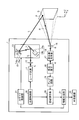
- FIG. 1 is a schematic configuration diagram of a laser radar device according to the present embodiment.
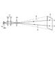
- FIG. 2 is a schematic view showing a peripheral configuration including the light receiving side optical system.
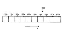
- FIG. 3A is a view showing a modified example of the light receiving element.
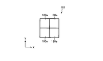
- FIG. 3B is a view showing a modified example of the light receiving element.
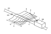
- FIG. 4A is a perspective view showing a configuration in which a laser radar device is mounted on a train traveling on a track.
- FIG. 4B is a side view showing a configuration in which a laser radar device is mounted on a train traveling on a track.
- FIG. 5 is a perspective view showing a configuration in which a laser radar device is mounted on a vehicle.
- FIG. 1 is a schematic configuration diagram of a laser radar device according to the present embodiment.
- the laser radar device 1 is configured to emit laser light in a horizontal direction (first direction) X of a predetermined measurement target area A set in advance and a vertical direction (second direction) Y orthogonal to the horizontal direction X.
- the light L is irradiated while being scanned, and the reflected light R of the laser light L is received to generate three-dimensional information of the measurement target area A.
- the laser radar device 1 is mounted forward of the traveling direction of a vehicle (traveling body) such as a train traveling on a track, for example, and generates three-dimensional information of the measurement target area A set in the traveling direction of the vehicle.
- a vehicle traveling body
- the laser radar device 1 includes a laser light source 11, a light emitting side lens 12, a scanner 13, a light receiving side lens 16, a light receiving side optical system 17, a light receiving element 18, and an amplifier circuit 19. , A distance calculation unit 20, an information generation unit 21, a light source control unit 30, and a scanner control unit 31.
- the light source control unit 30 controls the operation of the laser light source 11.
- the scanner control unit 31 controls the operation of the scanner 13.
- the light source control unit 30 has a master clock of the laser radar device 1 and transmits a pulse-like light emission synchronization signal to the distance calculation unit 20 simultaneously with the light emission of the laser light L.
- the laser radar device 1 irradiates the laser light L while scanning in the horizontal direction X and the vertical direction Y of the measurement target area A.
- the measurement target area A is an area set at a position away from the laser radar device 1 by a predetermined distance.
- the measurement target area A is updated as needed according to the travel of the vehicle.
- the laser light source 11 emits a laser beam L.
- the laser beam L for example, a laser beam having a wavelength of 200 to 2000 nm is used.
- the laser light source 11 includes, for example, a laser diode, and emits the laser light L in a pulse shape based on a light emission command of the light source control unit 30.
- the light transmission side lens 12 is configured by a single convex lens or a combination of a convex lens and a concave lens, and shapes the laser light L emitted from the laser light source 11 into a point shape (beam shape).
- the scanner 13 scans the laser light L formed in a point shape in the horizontal direction X and the vertical direction Y of the measurement target area A, respectively.
- the scanner 13 has a function of two-dimensionally scanning the measurement target area A, and a horizontal scanning unit 14 which scans the laser light L in the horizontal direction X and a vertical scanning unit 15 which scans the laser light L in the vertical direction Y
- the horizontal scanning unit 14 and the vertical scanning unit 15 are, for example, galvano scanners, and include galvano mirrors 14a and 15a that are plane mirrors, and drive motors 14b and 15b that swing mirror surfaces of the galvano mirrors 14a and 15a. There is.
- the horizontal scanning unit 14 drives the drive motor 14 b under the control of the scanner control unit 31 to swing the galvano mirror 14 a.
- the laser light L collected by the light transmission side lens 12 is deflected at an angle in the horizontal direction by the galvano mirror 14 a and scanned in the horizontal direction X of the measurement target area A.
- the vertical scanning unit 15 drives the drive motor 15b to swing the galvano mirror 15a.
- the angle in the vertical direction of the laser beam L reflected by the galvano mirror 14a is changed, and scanning is performed in the vertical direction Y of the area A to be measured.
- a configuration using a galvano scanner has been described as an example of the horizontal scanning unit 14 and the vertical scanning unit 15.
- the present invention is not limited to this configuration. For example, using a polygon scanner having a polygon mirror Also good.
- the scanner control unit 31 controls the operation of the drive motors 14 b and 15 b based on a predetermined scanning pattern. Thereby, the point-like laser light L is irradiated to the measurement target area A according to the scanning pattern, and the points (areas) in the irradiated measurement target area A become the measurement points S sequentially. In this case, the scanner control unit 31 acquires the mirror angles (transmission control angles) of the galvano mirrors 14 a and 15 a corresponding to the measurement points S, and transmits the mirror angles to the information generation unit 21. In the present embodiment, the scanner 13 irradiates the measurement target area A while scanning a point-like (beam-like) laser beam L.
- the irradiation power density of the laser beam L irradiated to the measurement object area A can be increased, and the signal intensity can be improved.
- measurement performance can be secured even under environmental conditions (for example, fog environment or rain environment) where the transmittance of the laser light L is low.
- the light receiving side lens 16 receives the reflected light R reflected from each measurement point S of the measurement target area A.
- the light receiving side optical system 17 focuses the reflected light R received by the light receiving side lens 16 in the horizontal direction X and the vertical direction Y, respectively.
- FIG. 2 is a schematic view showing a peripheral configuration including the light receiving side optical system. As shown in FIG. 2, the reflected light R reflected at each measurement point S in the measurement target area A is received by the light receiving side lens 16. The light receiving side lens 16 forms an image of each measurement point S at a predetermined position (image forming position) on the downstream side of the light receiving side lens 16.
- the light receiving side optical system 17 includes a relay lens 35 disposed at an image forming position of the light receiving side lens 16 and a condensing lens 36 disposed downstream of the relay lens 35.
- the relay lens 35 and the condensing lens 36 are provided one by one, but it goes without saying that a lens unit in which a plurality of lenses are combined may be used.
- the relay lens 35 is formed of a convex lens, and holds the image forming information of the light receiving side lens 16 at the image forming position, and substantially collimates the light flux thereafter. Have a function to transmit to In the present embodiment, the relay lens 35 is disposed at the imaging position of the light receiving side lens 16. However, the present invention is not limited to this. It may be arranged behind.
- the condenser lens 36 is a convex lens, and has the function of condensing all parallel light beams transmitted from the relay lens 35, that is, the imaging information in the horizontal direction X and the vertical direction Y toward the light receiving element 18. For this reason, the light receiving side optical system 17 can condense the imaging information of the light receiving side lens 16 on the light receiving surface 18A of the light receiving element 18 with a simple configuration in which two types of lenses are combined. It is possible to realize The light receiving element 18 is formed by a photoelectric conversion element (for example, a photodiode) that receives the reflected light R and converts it into a current, and is formed by a single element having a single pixel. Therefore, it is possible to respond to the short pulse laser beam L.
- a photoelectric conversion element for example, a photodiode
- the light receiving element 18 receives the reflected light R collected by the light receiving side optical system 17 and outputs a reception signal based on the laser light L contained in the received reflected light R.
- the amplifier circuit 19 amplifies the reception signal output from the light receiving element 18 as a voltage signal. Since the reception signal output from the light receiving element 18 is a weak current signal, the amplifier circuit 19 converts the current signal into a voltage signal and outputs the voltage signal to the distance calculation unit 20.
- the light receiving element 18 and the amplifier circuit 19 are provided to constitute a light receiving unit.
- the distance calculation unit 20 calculates distance information of the measurement point S of the measurement target area A based on the reception signal amplified by the amplifier circuit 19.
- the distance calculation unit 20 receives the pulse-like light emission synchronization signal transmitted from the light source control unit 30 and the reception signal transmitted from the amplifier circuit 19, and the measurement point S of the measurement target area A where the laser light L is irradiated. The distance to the point is calculated, and the distance information is transmitted to the information generation unit 21.
- the distance calculation unit 20 measures the time from the emission of the laser light L to the reception of the reflected light R based on the light emission synchronization signal and the reception signal, and the laser based on the measurement time. The distance to the measurement point S which reflected the light L is calculated.
- the distance calculation unit 20 may transmit the light reception intensity included in the reception signal to the information generation unit 21 in association with the distance information as well as the distance information.
- the information generation unit 21 generates three-dimensional information of the measurement target area A based on the distance information calculated by the distance calculation unit 20 and the position information of the measurement point S.
- the information generation unit 21 acquires coordinate information at the measurement point S based on distance information to the measurement point S and position information of the measurement point S in the horizontal direction X and vertical direction Y, and exists in the measurement target area A.
- Three-dimensional information of the measurement target area A is generated from the coordinate information distribution of the plurality of measurement points S.
- the information generation unit 21 acquires the mirror angles (light transmission control angles) of the galvano mirrors 14a and 15a related to the measurement point S transmitted from the scanner control unit 31, and the horizontal direction X of the measurement point S is acquired based on this mirror angle. And calculate position information in the vertical direction Y.
- the three-dimensional information of the measurement target area A generated by the information generation unit 21 is transmitted to an external device 25 (for example, a computer of a vehicle or the like) in a wired or wireless manner, and is used by the external device 25.
- an external device 25 for example, a computer of a vehicle or the like
- the condensing lens 36 combines all the image forming information of the light receiving side lens 16 transmitted from the relay lens 35 on the light receiving surface 18 A of the light receiving element 18 formed of a single element. Collect light. Therefore, the reflected light R from any measurement point S of the measurement target area A is focused on the light receiving surface 18A of the light receiving element 18, so that the light receiving element 18 constantly detects the entire measurement target area A It can be put into view. Therefore, the reflected light from the measurement target area A can be treated as single information.
- a plurality of light receiving elements are arranged and arranged, and an addition circuit for adding received signals from these light receiving elements is not necessary, and simplification of the circuit configuration can be realized.
- the light receiving element 18 is formed of a single element composed of a single pixel, the miniaturization of the light receiving element 18 can be realized, and hence the miniaturization of the laser radar device 1 can be realized.
- a long light receiving element array in which long light receiving elements described in Japanese Patent No. 5602225 are arranged in an array in a direction orthogonal to the long direction of the light receiving element and the reception signal of each long light receiving element are added
- an adding circuit By providing an adding circuit, a scanless on the light receiving side is realized while securing a wide two-dimensional field of view.
- the elongated light receiving elements in an array in the direction orthogonal to the longitudinal direction of the light receiving elements, the elongated light receiving element array is enlarged, which goes against the purpose of downsizing the laser radar device. There is a fear.
- the laser radar device 1 is provided with the light receiving side optical system 17 so that the reflected light from any measurement point S of the measurement target area A is provided on the light receiving surface 18A of the light receiving element 18
- the light receiving element 18 can always keep the entire area A to be measured within the sensor field of view. Therefore, the reflected light from the measurement target area A can be treated as single information, and miniaturization can be realized.
- the light receiving element 18 having a single pixel is disposed at the image forming position of the light receiving side lens 16.
- the area of the light receiving surface 18A of the light receiving element 18 is extremely small compared to the area of the image forming information at the image forming position of the light receiving side lens 16. I can not do it.
- a light receiving element consisting of a single element having a light receiving surface equal to or greater than the imaging information at the imaging position of the light receiving side lens 16 is required.
- the pixel size is increased, there is a problem that the responsiveness as a light receiving element (photodiode) is reduced.
- the light receiving side optical system 17 includes a relay lens 35 disposed at an image forming position of the light receiving side lens 16 and a condenser lens 36 disposed downstream of the relay lens 35.
- the condensing lens 36 responds to the light receiving surface 18 A of the light receiving element 18 formed of a single element, by focusing all the image forming information of the light receiving side lens 16 transmitted from the relay lens 35. It is possible to cover information of the entire field of view of the light receiving side lens 16 regardless of the pixel shape of the light receiving element 18 without deterioration. For this reason, the light receiving element 18 can be configured as a sensor of a rectangular, square or circular single element, and the selection range of the light receiving element can be widened.
- FIGS. 3A and 3B show a modification of the light receiving element.
- the light receiving element 18 is formed by a single element having a single pixel, but as shown in FIG. 3-1, for example, a single pixel 180a may be in a predetermined direction (for example, a horizontal direction). It is also possible to use a line-shaped light receiving element (line sensor) 180 formed in line with X).
- the pixels 180a for collecting the reflected light can be used as the light receiving elements. According to this, the reflected light can be reliably received by the light receiving element, and the measurement quality can be secured.
- the linear light receiving element (line sensor) 180 as shown in FIG. 3-2, a plurality of (for example, two) single pixels 180a are formed in the horizontal direction X and the vertical direction Y, respectively.
- the light receiving element group 181 may be used.
- Fig. 4-1 is a perspective view showing a configuration in which a laser radar device is mounted on a train traveling on a track
- Fig. 4-2 is a side showing a configuration in which a laser radar device is mounted on a train traveling on a track FIG.
- the laser radar device 1 is mounted on a train (running body) 100.
- the train 100 travels on the track 101, and may be configured to be driven by a driver's operation or to be automatically driven by a computer.
- the laser radar device 1 is provided on the upper front side of the train 100, and monitors a measurement target area A set forward in the traveling direction of the train 100. As described above, the laser radar device 1 does not have the scanner on the reception side, and therefore, the laser radar device 1 can be miniaturized. Therefore, in the train 100 on which the laser radar device 1 is mounted, the influence of the reduction of free space in the train 100 or the protrusion to the outside of the train 100 due to the layout of the laser radar device 1 is minimized. Can.
- the measurement target area A is set as a traveling road surface ahead in the traveling direction including the track 101 over a predetermined distance D (for example, 300 to 500 m) from the train 100, and the measurement target area A is It is updated at any time as the train 100 travels.
- the laser radar device 1 scans and irradiates the laser light L toward the measurement target area A, and generates three-dimensional information of the measurement target area A based on distance information and position information of each measurement point S.
- the train 100 is not shown, but a computer for acquiring three-dimensional information of the measurement area A output from the laser radar device 1 as the external device 25 (FIG. 1), and this computer based on the three-dimensional information And a display for displaying the shape of the drawn measurement target area A.
- These computers and displays are disposed in the cab of the train 100.
- the three-dimensional information generated by the laser radar device 1 is output to the computer of the train 100 at any time and displayed on the display via the computer. Therefore, for example, even when there is an obstacle 102 on the line 101, the display of the area to be measured A including the obstacle 102 is displayed on the display, thus providing driving assistance to the driver. can do.
- the shape change in the direction of movement in the measurement target area A exceeds a predetermined threshold, a warning alert is issued on the assumption that the obstacle 102 is likely to be present. It may be configured to inform.
- FIG. 5 is a perspective view showing a configuration in which a laser radar device is mounted on a vehicle.
- the laser radar device 1 is mounted on a vehicle (running body) 150.
- the vehicle 150 travels freely on the road surface, and may be configured to be driven by the driver's steering or to be automatically driven by a computer.
- the laser radar device 1 is provided on the front upper portion of the vehicle 150, and monitors the measurement target area A set on the terrain 200 in front of the traveling direction of the vehicle 150. As described above, the laser radar device 1 does not have the scanner on the reception side, and therefore, the laser radar device 1 can be miniaturized. For this reason, the vehicle 150 mounted with the laser radar device 1 minimizes the reduction of free space in the vehicle 150 or the influence of the protruding portion to the outside of the vehicle 150 due to the layout of the laser radar device 1. Can.
- the measurement target area A is set on the surface of the topography 200 ahead in the traveling direction over a predetermined distance D (for example, 100 m) from the vehicle 150. Updated accordingly.
- the laser radar device 1 scans and irradiates the laser light L toward the measurement target area A, and based on the distance information and position information of each measurement point S, three-dimensional information of the measurement target area A (terrain 200) Generate In FIG. 5, the topography 200 is described as including a large raised portion 200A and a small flat portion 200B.
- the vehicle 150 is provided with the navigation apparatus which performs the route guidance of this vehicle 150 as the external apparatus 25 (FIG. 1).
- the navigation device includes a control unit that controls the entire navigation device, and a display that displays a route (map information), and three-dimensional information of the measurement target area A is output to the control unit.
- the navigation apparatus sets a path 201 passing through the flat portion 200B having a small relief, based on the three-dimensional information of the measurement target area A, avoiding the crest portion 200A having a large relief. According to this configuration, even when traveling on a landform 200 with severe undulations, it is possible to travel on the route 201 including the flat portion 200B as much as possible, and driving assistance to the driver can be realized.
- safe automatic driving can be realized by traveling on the route 201 including the flat portion 200B as much as possible based on the three-dimensional information generated by the laser radar device 1.
- the composition which carries laser radar device 1 in the run object of train 100 or vehicles 150 if it is the run object which carries out self-propelled, it will not restrict to these.
- the laser radar device 1 is mounted on the traveling body, but, for example, the measurement target area A is installed on a pillar standing by the side of intersections or crossings where the measurement target area A is set.
- the configuration may be such that three-dimensional information of the measurement target area A is generated by receiving the reflected light R of a guardrail, a stationary object such as a tree, etc.).
- the laser radar device 1 includes the laser light source 11, the light transmitting side lens 12 for forming the laser light L emitted from the laser light source 11 into a point, and the point
- the scanner 13 irradiates the laser beam L while scanning in the horizontal direction X and the vertical direction Y of the measurement target area A, the light receiving side lens 16 receives the reflected light R reflected from the measurement target area A, and the light receiving A light receiving side optical system 17 for collecting the reflected light R received by the side lens 16 in the horizontal direction X and a vertical direction Y, and a light receiving element 18 for receiving the reflected light R collected by the light receiving side optical system 17
- the information generation unit 21 that generates three-dimensional information of the measurement target area A based on the reception signal output from the light reception element 18, thereby achieving downsizing of the light reception element 18 and receiving the entire measurement target area A.
- Can be accommodated in the sensor field of view of the device 18 can be realized scanless the light-receiving side with a simple
- the light receiving element 18 is configured of a single element having a single pixel, the entire measurement target area A can be included in the sensor field of view of the single element. For this reason, the addition circuit which adds the reception signal of the light receiving element 18 becomes unnecessary, and simplification of a circuit structure can be implement
- the light receiving side optical system 17 is disposed at the image forming position of the light receiving side lens 16, and relay lens 35 for transmitting while holding the image forming information at the image forming position, and the relay lens Since the collimated light beam transmitted from the light source 35 is provided with a condenser lens 36 for condensing the collimated light flux transmitted from the light source 35 toward the light receiving element 18, the imaging information of the light receiving side lens 16 is received by the light receiving element The light can be collected on the light receiving surface 18A.
- the information generation unit 21 determines the distance to the measurement point S of the measurement target area A acquired from the light round trip time from the irradiation of the laser light L to the light reception by the light receiving element 18. To generate three-dimensional information of the measurement area A from the information and each position information of the measurement point S in the horizontal direction X and the vertical direction Y acquired based on the mirror angle of the scanner 13 at the time of irradiating the laser light L With the field-of-view scanning on the light receiving side, acquisition of spatial position coordinates of the received signal becomes unnecessary, and the load of signal processing for generating three-dimensional information can be reduced.
- the above-described laser radar device 1 is mounted on the train 100 or the vehicle 150, three-dimensional information of the traveling route of the train 100 or the vehicle 150 can always be acquired. It can be carried out.
Landscapes
- Physics & Mathematics (AREA)
- Engineering & Computer Science (AREA)
- General Physics & Mathematics (AREA)
- Radar, Positioning & Navigation (AREA)
- Remote Sensing (AREA)
- Computer Networks & Wireless Communication (AREA)
- Electromagnetism (AREA)
- Optics & Photonics (AREA)
- Mechanical Engineering (AREA)
- Health & Medical Sciences (AREA)
- Biomedical Technology (AREA)
- General Health & Medical Sciences (AREA)
- Optical Radar Systems And Details Thereof (AREA)
- Length Measuring Devices By Optical Means (AREA)
- Measurement Of Optical Distance (AREA)
- Mechanical Optical Scanning Systems (AREA)
Abstract
レーザ光源11と、レーザ光源11から発光されるレーザ光Lを点状に成形する送光側レンズ12と、点状に成形されたレーザ光Lを、計測対象エリアAの水平方向X及び垂直方向Yに走査させながら照射するスキャナ13と、計測対象エリアAから反射される反射光Rを受光する受光側レンズ16と、受光側レンズ16で受光された反射光Rを、水平方向X及び垂直方向Yにそれぞれ集光する受光側光学系17と、受光側光学系17で集光された反射光Rを受光する受光素子18と、受光素子18が出力した受信信号に基づき、計測対象エリアAの3次元情報を生成する情報生成部21と、を備える。
Description
本発明は、レーザ光を走査させることで計測対象エリアの3次元情報を生成するレーザレーダ装置、及び、走行体に関する。
一般に、レーザ光を計測対象エリアに走査させながら照射し、この計測対象エリアに存在する物体などからの反射光を受光素子で受光することによって得られる受光信号の分布から計測対象エリアの3次元情報を生成するレーザレーダ装置が知られている。この種のレーザレーダ装置では、レーザ光の送光側、及び、反射光の受光側の各々にスキャナを設け、走査時における送光側のスキャナのミラー角(レーザ光の送光角)に合せて受光側のスキャナのミラー角(反射光の受光角)を随時調整することで反射光を受光素子に入射させている。この構成では、送光側及び受光側の両方にスキャナを設けるため、レーザレーダ装置全体が大型化する問題があった。
上記した問題を解決するために、従来、受光側にスキャナを設けないレーザレーダ装置が提案されている(特許文献1参照)。このレーザレーダ装置は、長尺受光素子を受光素子の長尺方向と直交する方向にアレイ状に並べた長尺受光素子アレイと、受信信号を増幅するトランスインピーダンスアンプアレイと、トランスインピーダンスアンプアレイの各素子からの受信信号を加算する加算回路と、を備えることで、広い2次元視野を確保しつつ受光側のスキャンレスを実現している。
しかしながら、従来の構成では、長尺受光素子を受光素子の長尺方向と直交する方向にアレイ状に並べた長尺受光素子アレイを備えるため、長尺受光素子アレイ全体が大型化してしまう問題があった。また、アレイ状に並べられた各長尺受光素子が受信した受信信号を加算する加算回路が必要となり、装置構成及び信号処理が煩雑になる問題があった。
本発明は、上記に鑑みてなされたものであって、受光素子の小型化を図りつつ、受光側のスキャンレスを簡単な構成で実現できるレーザレーダ装置、及び、走行体を提供することを目的とする。
上述した課題を解決し、目的を達成するために、本発明は、レーザ光源と、レーザ光源から照射されるレーザ光を点状に成形する送光側レンズと、点状に成形されたレーザ光を、計測対象エリアの第1方向及び該第1方向に直交する第2方向に走査させながら照射するスキャナと、計測対象エリアから反射される反射光を受光する受光側レンズと、受光側レンズで受光された反射光を、第1方向及び第2方向にそれぞれ集光する受光側光学系と、受光側光学系で集光された反射光を受光し、受光した反射光に含まれるレーザ光に基づいた受信信号を出力する受光部と、受光部が出力した受信信号に基づき、計測対象エリアの3次元情報を生成する情報生成部と、を備えることを特徴とする。
この構成によれば、受光側レンズで受光された反射光を、第1方向及び第2方向にそれぞれ集光する受光側光学系と、受光側光学系で集光された反射光を受光し、受光した反射光に含まれるレーザ光に基づいた受信信号を出力する受光部とを備えるため、この受光部の受光素子を小型化することができるとともに、計測対象エリア全体を受光素子のセンサ視野に収めることができ、受光側のスキャンレスを簡単な構成で実現できる。
この構成において、単一の受光素子を有する構成としても良い。この構成によれば、計測対象エリア全体を単一の受光素子のセンサ視野に収めることができるため、受光素子の受信信号を加算する加算回路が不要となり、回路構成の簡素化を実現できる。
また、受光側光学系は、受光側レンズの結像位置付近、または後方に配置されたリレーレンズと、リレーレンズから伝送された略平行光束を受光部に向けて集光させる集光レンズとを備えても良い。この構成によれば、2種類のレンズを組み合わせた簡単な構成で、受光側レンズの結像情報を受光部に集光させることができる。
また、情報生成部は、レーザ光が照射されてから受光部で受光されるまでの光往復時間から取得された計測対象エリアまでの距離情報と、レーザ光を照射した際のスキャナの送光制御角度に基づき取得された第1方向及び第2方向の各位置情報とから計測対象エリアの3次元情報を生成しても良い。この構成によれば、受光側の視野スキャンにより受信信号の空間位置座標取得が不要となるため、3次元情報を生成するための信号処理の負荷を軽減できる。
また、上記したレーザレーダ装置を走行体に搭載しても良い。この構成によれば、走行体の走行経路の3次元情報を常に取得することができ、走行体の運転支援を行うことができる。
本発明によれば、受光側レンズで受光された反射光を、第1方向及び第2方向にそれぞれ集光する受光側光学系と、受光側光学系で集光された反射光を受光し、受光した反射光に含まれるレーザ光に基づいた受信信号を出力する受光部とを備えるため、この受光部の受光素子を小型化することができるとともに、計測対象エリア全体を受光素子のセンサ視野に収めることができ、受光側のスキャンレスを簡単な構成で実現できる。
以下に、本発明に係る実施形態を図面に基づいて詳細に説明する。なお、この実施形態によりこの発明が限定されるものではない。また、実施形態における構成要素には、当業者が置換可能かつ容易なもの、あるいは実質的に同一のものが含まれる。さらに、以下に記載した構成要素は適宜組み合わせることが可能である。
図1は、本実施形態に係るレーザレーダ装置の概略構成図である。レーザレーダ装置1は、図1に示すように、予め設定された所定の計測対象エリアAの水平方向(第1方向)X及びこの水平方向Xに直交する垂直方向(第2方向)Yにレーザ光Lを走査しながら照射し、このレーザ光Lの反射光Rを受光して計測対象エリアAの3次元情報を生成する。このレーザレーダ装置1は、例えば、線路上を走行する列車などの車両(走行体)の進行方向前方に搭載され、車両の進行方向に設定された計測対象エリアAの3次元情報を生成する。これにより、生成された3次元情報を利用して、車両の進行方向に障害物が存在するか否かを判別できる。
レーザレーダ装置1は、図1に示すように、レーザ光源11と、送光側レンズ12と、スキャナ13と、受光側レンズ16と、受光側光学系17と、受光素子18と、アンプ回路19と、距離演算部20と、情報生成部21と、光源制御部30と、スキャナ制御部31と、を有する。光源制御部30は、レーザ光源11の動作を制御する。スキャナ制御部31は、スキャナ13の動作を制御する。光源制御部30は、レーザレーダ装置1のマスタークロックを有し、レーザ光Lの発光と同時にパルス状の発光同期信号を距離演算部20に発信する。
レーザレーダ装置1は、レーザ光Lを、計測対象エリアAの水平方向X及び垂直方向Yに走査しながら照射する。計測対象エリアAは、レーザレーダ装置1から所定距離離れた位置に設定されたエリアである。レーザレーダ装置1が、例えば、列車などの車両に搭載された場合には、計測対象エリアAは車両の走行に応じて随時更新される。
レーザ光源11は、レーザ光Lを発光する。レーザ光Lは、例えば、200~2000nmの波長のレーザ光が用いられる。特に、レーザレーダ装置1を屋外の広い空間で使用する場合には、800~2000nmの波長のレーザ光を用いることで、安定した計測を実現できる。レーザ光源11は、例えば、レーザダイオードなどから構成され、光源制御部30の発光指令に基づきレーザ光Lをパルス状に発光する。送光側レンズ12は、凸レンズ単体、もしくは凸レンズと凹レンズとの組み合わせで構成され、レーザ光源11から発光されるレーザ光Lを点状(ビーム状)に成形する。スキャナ13は、点状に成形されたレーザ光Lを、計測対象エリアAの水平方向X及び垂直方向Yにそれぞれ走査する。
スキャナ13は、計測対象エリアAを2次元的に走査する機能を有し、レーザ光Lを水平方向Xに走査させる水平走査部14と、レーザ光Lを垂直方向Yに走査させる垂直走査部15とを備える。水平走査部14及び垂直走査部15は、例えば、ガルバノスキャナにより構成され、平面鏡であるガルバノミラー14a,15aと、ガルバノミラー14a,15aの鏡面を揺動させる駆動モータ14b,15bと、を備えている。水平走査部14は、スキャナ制御部31の制御の下、駆動モータ14bを駆動させてガルバノミラー14aを揺動させる。これにより、送光側レンズ12で集光されたレーザ光Lは、ガルバノミラー14aによって水平方向の角度が偏向され、計測対象エリアAの水平方向Xに走査される。また、垂直走査部15は、スキャナ制御部31の制御の下、駆動モータ15bを駆動させてガルバノミラー15aを揺動させる。これにより、ガルバノミラー14aを反射したレーザ光Lの垂直方向の角度が変更され、計測対象エリアAの垂直方向Yに走査される。なお、本実施形態では、水平走査部14及び垂直走査部15の一例として、ガルバノスキャナを用いた構成を説明したが、この構成に限るものではなく、例えば、ポリゴンミラーを有するポリゴンスキャナを用いても良い。
スキャナ制御部31は、所定の走査パターンに基づき、駆動モータ14b,15bの動作を制御する。これにより、点状のレーザ光Lは、走査パターンに則して計測対象エリアAに照射され、この照射された計測対象エリアA内の点(領域)が順次、計測点Sとなる。この場合、スキャナ制御部31は、各計測点Sに対応するガルバノミラー14a,15aのミラー角(送光制御角度)を取得し、このミラー角を情報生成部21に発信する。本実施形態では、スキャナ13は、点状(ビーム状)のレーザ光Lを走査しながら計測対象エリアAに照射する。このため、計測対象エリアAに照射されるレーザ光Lの照射パワー密度が増加し、信号強度を向上させることができる。これにより、レーザ光Lの透過率が低い環境条件(例えば、霧環境や雨環境)下でも計測性能を確保することができる。
また、受光側レンズ16は、計測対象エリアAの各計測点Sから反射される反射光Rを受光する。受光側光学系17は、受光側レンズ16で受光された反射光Rを水平方向X及び垂直方向Yにそれぞれ集光する。
図2は、受光側光学系を含む周辺構成を示す模式図である。図2に示すように、計測対象エリアAの各計測点Sで反射される反射光Rは、それぞれ受光側レンズ16で受光される。この受光側レンズ16は、各計測点Sの像を受光側レンズ16の下流側の所定位置(結像位置)で結像する。
受光側光学系17は、受光側レンズ16の結像位置に配置されるリレーレンズ35と、このリレーレンズ35の下流側に配置される集光レンズ36とを備える。この図2では、リレーレンズ35と集光レンズ36とを1枚ずつ備えた構成としているが、各レンズを複数組み合わせたレンズユニットとしても良いことは勿論である。リレーレンズ35は、凸レンズで構成され、結像位置における受光側レンズ16の結像情報を保持したまま、それ以降の光束を略平行化するレンズであり、この結像情報をそのまま集光レンズ36に伝送する機能を有する。また、本実施形態では、リレーレンズ35は、受光側レンズ16の結像位置に配置する構成としたが、これに限るものではなく、受光側レンズ16の結像位置付近、または結像位置の後方に配置しても良い。集光レンズ36は凸レンズで構成され、リレーレンズ35から伝送された平行光束、すなわち結像情報のすべてを受光素子18に向けて水平方向X及び垂直方向Yに集光させる機能を有する。このため、受光側光学系17は、2種類のレンズを組み合わせた簡単な構成で、受光側レンズ16の結像情報を受光素子18の受光面18Aに集光させることができ、受光側のスキャンレスを実現できる。受光素子18は、反射光Rを受光して電流に変換する光電変換素子(例えば、フォトダイオード)で形成されており、単一のピクセルを有する単一素子で形成されている。このため、短いパルスのレーザ光Lに応答することができる。
受光素子18は、受光側光学系17で集光された反射光Rを受光し、受光した反射光Rに含まれるレーザ光Lに基づいた受信信号を出力する。アンプ回路19は、受光素子18が出力した受信信号を電圧信号として増幅する。受光素子18が出力する受信信号は、微弱な電流信号であるため、アンプ回路19は、電流信号を電圧信号に変換して距離演算部20に出力する。本実施形態では、受光素子18とアンプ回路19とを備えて受光部を構成する。
距離演算部20は、アンプ回路19にて増幅された受信信号に基づき、計測対象エリアAの計測点Sの距離情報を演算する。距離演算部20は、光源制御部30から発信されたパルス状の発光同期信号とアンプ回路19から発信された受信信号とを受信し、レーザ光Lが照射された計測対象エリアAの計測点Sまでの距離を演算し、距離情報を情報生成部21に発信する。具体的には、距離演算部20は、発光同期信号と受信信号とに基づいてレーザ光Lを発光してから反射光Rを受光するまでの時間を計測するとともに、この計測時間に基づいてレーザ光Lを反射した計測点Sまでの距離を演算する。また、距離演算部20は、距離情報とともに、受信信号に含まれる受光強度を距離情報と関連づけて情報生成部21に発信しても良い。
情報生成部21は、この距離演算部20が演算した距離情報、及び、計測点Sの位置情報に基づき、計測対象エリアAの3次元情報を生成する。情報生成部21は、計測点Sまでの距離情報と、該計測点Sの水平方向X及び垂直方向Yの位置情報とに基づき、計測点Sにおける座標情報を取得し、計測対象エリアAに存在する複数の計測点Sの座標情報分布から計測対象エリアAの3次元情報を生成する。情報生成部21は、スキャナ制御部31から発信された計測点Sに関するガルバノミラー14a,15aのミラー角(送光制御角度)を取得し、このミラー角に基づき、該計測点Sの水平方向X及び垂直方向Yの位置情報を演算する。この構成では、受光側の視野スキャンによる受信信号の空間位置座標取得が不要となるため、3次元情報を生成するための信号処理の負荷を軽減できる。情報生成部21で生成された計測対象エリアAの3次元情報は、外部機器25(例えば、車両のコンピュータ等)に有線または無線にて送信され、この外部機器25で利用される。
本実施形態のレーザレーダ装置1は、集光レンズ36は、リレーレンズ35から伝送された受光側レンズ16の結像情報のすべてを、単一素子で形成された受光素子18の受光面18Aに集光する。このため、受光素子18の受光面18Aには、計測対象エリアAのいずれの計測点Sからの反射光Rも集光されることにより、受光素子18は、常時、計測対象エリアA全体をセンサ視野に収めることができる。従って、計測対象エリアAからの反射光を単一の情報として取り扱うことができる。これにより、従来のように、複数の受光素子を並べて配置するとともに、これら受光素子の受信信号を加算する加算回路が不要となり、回路構成の簡素化を実現できる。さらに、本実施形態では、受光素子18を単一ピクセルからなる単一素子で形成したため、受光素子18の小型化を実現し、ひいては、レーザレーダ装置1の小型化を実現できる。
例えば、特許第5602225号公報に記載されている長尺受光素子を受光素子の長尺方向と直交する方向にアレイ状に並べた長尺受光素子アレイと、各長尺受光素子の受信信号を加算する加算回路とを備えることで、広い2次元視野を確保しつつ受光側のスキャンレスを実現している。しかし、従来技術では、長尺受光素子を受光素子の長尺方向と直交する方向にアレイ状に並べることで、長尺受光素子アレイが大型化してしまい、レーザレーダ装置の小型化という目的に反する恐れがある。また、アレイ状に並べられた各長尺受光素子が受信した受信信号を加算する加算回路が必要となり、装置構成が煩雑になる恐れがあった。これに対して、レーザレーダ装置1は、上述したように、受光側光学系17を設けたことにより、受光素子18の受光面18Aには、計測対象エリアAのどの計測点Sからの反射光Rも集光されることにより、受光素子18は、常時、計測対象エリアA全体をセンサ視野に収めることができる。従って、計測対象エリアAからの反射光を単一の情報として取り扱うことができ、小型化を実現できる。
ここで、単一ピクセルを有する受光素子18を受光側レンズ16の結像位置に配置する構成が想定される。しかし、この構成では、受光素子18の受光面18Aの面積が、受光側レンズ16の結像位置での結像情報の面積に比べて極めて小さいため、計測対象エリアAの一部分しかセンサ視野に収めることができない。また、計測対象エリアA全体のセンサ視野を確保するためには、受光側レンズ16の結像位置での結像情報と同等以上の受光面を有する単一素子からなる受光素子が必要となるが、ピクセルサイズが大きくなると、受光素子(フォトダイオード)としての応答性が低下する問題がある。
これに対して、本実施形態では、受光側光学系17は、受光側レンズ16の結像位置に配置されるリレーレンズ35と、このリレーレンズ35の下流側に配置される集光レンズ36とを備え、集光レンズ36は、リレーレンズ35から伝送された受光側レンズ16の結像情報のすべてを単一素子で形成された受光素子18の受光面18Aに集光するため、応答性を低下することなく、受光側レンズ16の有する視野全体の情報を受光素子18の画素形状に関係なくカバーすることを可能としている。このため、受光素子18は、長方形、正方形や円形の単一素子のセンサでも構成可能となり、受光素子の選択幅を広くすることができる。
次に、受光素子の変形例について説明する。図3-1及び図3-2は、受光素子の変形例を示す図である。上記した実施形態では、受光素子18は、単一ピクセルを有する単一素子で形成された構成としたが、図3-1に示すように、例えば、単一ピクセル180aを所定方向(例えば水平方向X)に連ねて形成されたライン状受光素子(ラインセンサ)180を用いることもできる。この構成では、レーザレーダ装置1の運用中に受光側レンズ16-リレーレンズ35-集光レンズ36による受光素子への集光位置がずれたり、集光サイズが最適点からずれて拡大した場合でも、ライン状受光素子180のうち、反射光が集光されるピクセル180aを受光素子として使用することができる。これによれば、反射光を確実に受光素子で受光することができ、計測品質を確保することができる。また、ライン状受光素子(ラインセンサ)180だけでなく、図3-2に示すように、単一ピクセル180aを水平方向X及び垂直方向Yにそれぞれ複数(例えば、2つ)連ねて形成された受光素子群181を用いてもよい。
次に、本実施形態のレーザレーダ装置1の適用例について説明する。図4-1は、線路上を走行する列車にレーザレーダ装置を搭載した構成を示す斜視図であり、図4-2は、線路上を走行する列車にレーザレーダ装置を搭載した構成を示す側方視図である。この適用例では、レーザレーダ装置1を列車(走行体)100に搭載している。列車100は、線路101上を走行するものであり、運転士の操縦によって運転される構成や、コンピュータによって自動運転される構成であっても良い。
レーザレーダ装置1は、列車100の前側上部に設けられ、この列車100の進行方向前方に設定される計測対象エリアAを監視するようになっている。このレーザレーダ装置1は、上述のように、受信側のスキャナを設けない構成であるため、レーザレーダ装置1の小型化を実現している。このため、このレーザレーダ装置1を搭載した列車100は、該レーザレーダ装置1の配置レイアウトによる列車100内の自由空間の減少、もしくは列車100外への突出部などの影響を最小限に抑えることができる。
計測対象エリアAは、具体的には、列車100から所定距離D(例えば300~500m)に亘って、線路101を含んだ進行方向前方の走行路面に設定されており、この計測対象エリアAは列車100の走行に応じて随時更新される。レーザレーダ装置1は、この計測対象エリアAに向けて、レーザ光Lを走査しながら照射し、各計測点Sの距離情報及び位置情報に基づき、計測対象エリアAの3次元情報を生成する。
列車100は、図示は省略するが、外部機器25(図1)として、レーザレーダ装置1から出力された計測対象エリアAの3次元情報を取得するコンピュータと、このコンピュータが3次元情報に基づいて描画した計測対象エリアAの形状を表示するディスプレイとを備える。これらコンピュータ及びディスプレイは、列車100の運転室に配置される。
この構成では、レーザレーダ装置1が生成した3次元情報は、随時、列車100のコンピュータに出力され、このコンピュータを介して、ディスプレイに表示される。このため、例えば、線路101上に障害物102が存在する場合であっても、この障害物102を含んだ計測対象エリアAの形状がディスプレイに表示されるため、運転士への運転支援を実現することができる。また、ディスプレイに形状を表示するだけでなく、計測対象エリアAにおける進行方向への形状変化が所定の閾値を超えた場合には、障害物102が存在する可能性が高いとして、注意警報を発報する構成としてもよい。
また、列車100がコンピュータによって自動運転される構成において、レーザレーダ装置1が生成した3次元情報に基づき、線路101上に障害物102が存在する場合には、列車100を停止することで安全な自動運転を実現できる。
図5は、車両にレーザレーダ装置を搭載した構成を示す斜視図である。この適用例では、レーザレーダ装置1を車両(走行体)150に搭載している。車両150は、路面上を自在に走行するものであり、運転手の操縦によって運転される構成や、コンピュータによって自動運転される構成であっても良い。
レーザレーダ装置1は、車両150の前側上部に設けられ、この車両150の進行方向前方の地形200上に設定される計測対象エリアAを監視するようになっている。このレーザレーダ装置1は、上述のように、受信側のスキャナを設けない構成であるため、レーザレーダ装置1の小型化を実現している。このため、このレーザレーダ装置1を搭載した車両150は、該レーザレーダ装置1の配置レイアウトによる車両150内の自由空間の減少、もしくは車両150外への突出部などの影響を最小限に抑えることができる。
計測対象エリアAは、具体的には、車両150から所定距離D(例えば100m)に亘って、進行方向前方の地形200の表面に設定されており、この計測対象エリアAは車両150の走行に応じて随時更新される。レーザレーダ装置1は、この計測対象エリアAに向けて、レーザ光Lを走査しながら照射し、各計測点Sの距離情報及び位置情報に基づき、計測対象エリアA(地形200)の3次元情報を生成する。この図5では、地形200は、起伏の大きな頂き部200Aと、起伏の小さな平坦部200Bとを備えるものとして説明する。
車両150は、図示は省略するが、外部機器25(図1)として、この車両150の経路案内を行うナビゲーション装置を備える。このナビゲーション装置は、ナビゲーション装置全体を制御する制御部と、経路(地図情報)を表示するディスプレイとを備え、計測対象エリアAの3次元情報は制御部に出力される。ナビゲーション装置は、計測対象エリアAの3次元情報に基づき、起伏の大きな頂き部200Aを避けて、起伏の小さな平坦部200Bを通る経路201を設定する。この構成によれば、起伏の激しい地形200を走行する場合であっても、なるべく平坦部200Bを含む経路201を走行することができ、運転手への運転支援を実現することができる。
また、車両150がコンピュータによって自動運転される構成において、レーザレーダ装置1が生成した3次元情報に基づき、なるべく平坦部200Bを含む経路201を走行することで安全な自動運転を実現できる。
上記した適用例では、レーザレーダ装置1を列車100や車両150の走行体に搭載する構成を説明したが、自走する走行体であればこれらに限るものではない。また、上記した適用例では、レーザレーダ装置1を走行体に搭載したが、例えば、計測対象エリアAが設定される交差点や踏切等の脇に立設された支柱上に計測対象エリアAを俯瞰するように配置され、レーザ光Lを水平方向X及び垂直方向Yにスキャンしながら照射し、計測対象エリアA内の物体(例えば、歩行者、自転車、二輪自動車、自動車等の移動物体や建物、ガードレール、樹木等の静止物体等)の反射光Rを受光することで、計測対象エリアAの3次元情報を生成する構成としても良い。
以上、説明したように、本実施形態に係るレーザレーダ装置1は、レーザ光源11と、レーザ光源11から発光されるレーザ光Lを点状に成形する送光側レンズ12と、点状に成形されたレーザ光Lを、計測対象エリアAの水平方向X及び垂直方向Yに走査させながら照射するスキャナ13と、計測対象エリアAから反射される反射光Rを受光する受光側レンズ16と、受光側レンズ16で受光された反射光Rを、水平方向X及び垂直方向Yにそれぞれ集光する受光側光学系17と、受光側光学系17で集光された反射光Rを受光する受光素子18と、受光素子18が出力した受信信号に基づき、計測対象エリアAの3次元情報を生成する情報生成部21とを備えるため、受光素子18の小型化を図るとともに、計測対象エリアA全体を受光素子18のセンサ視野に収めることができ、受光側のスキャンレスを簡単な構成で実現できる。
また、本実施形態によれば、受光素子18は、単一ピクセルを有する単一素子からなる構成としたため、計測対象エリアA全体を単一素子のセンサ視野に収めることができる。このため、受光素子18の受信信号を加算する加算回路が不要となり、回路構成の簡素化を実現できる。
また、本実施形態によれば、受光側光学系17は、受光側レンズ16の結像位置に配置され、該結像位置での結像情報を保持したまま伝送するリレーレンズ35と、リレーレンズ35から伝送された平行光束を受光素子18に向けて集光させる集光レンズ36とを備えるため、2種類のレンズを組み合わせた簡単な構成で、受光側レンズ16の結像情報を受光素子18の受光面18Aに集光させることができる。
また、本実施形態によれば、情報生成部21は、レーザ光Lが照射されてから受光素子18で受光されるまでの光往復時間から取得された計測対象エリアAの計測点Sまでの距離情報と、レーザ光Lを照射した際のスキャナ13のミラー角に基づき取得された計測点Sの水平方向X及び垂直方向Yの各位置情報とから計測対象エリアAの3次元情報を生成するため、受光側の視野スキャンにより受信信号の空間位置座標取得が不要となり、3次元情報を生成するための信号処理の負荷を軽減できる。
また、上記したレーザレーダ装置1は、列車100や車両150に搭載されるため、列車100または車両150の走行経路の3次元情報を常に取得することができ、列車100または車両150の運転支援を行うことができる。
1 レーザレーダ装置
11 レーザ光源
12 送光側レンズ
13 スキャナ
14 水平走査部
15 垂直走査部
16 受光側レンズ
17 受光側光学系
18 受光素子
18A 受光面
21 情報生成部
30 光源制御部
31 スキャナ制御部
35 リレーレンズ
36 集光レンズ
100 列車(走行体)
150 車両(走行体)
180 ライン状受光素子
180a 単一ピクセル
181 受光素子群
A 計測対象エリア
L レーザ光
R 反射光
S 計測点
X 水平方向(第1方向)
Y 垂直方向(第2方向)
11 レーザ光源
12 送光側レンズ
13 スキャナ
14 水平走査部
15 垂直走査部
16 受光側レンズ
17 受光側光学系
18 受光素子
18A 受光面
21 情報生成部
30 光源制御部
31 スキャナ制御部
35 リレーレンズ
36 集光レンズ
100 列車(走行体)
150 車両(走行体)
180 ライン状受光素子
180a 単一ピクセル
181 受光素子群
A 計測対象エリア
L レーザ光
R 反射光
S 計測点
X 水平方向(第1方向)
Y 垂直方向(第2方向)
Claims (5)
- レーザ光源と、
前記レーザ光源から発光されるレーザ光を点状に成形する送光側レンズと、
前記点状に成形された前記レーザ光を、計測対象エリアの第1方向及び該第1方向に直交する第2方向に走査させながら照射するスキャナと、
前記計測対象エリアから反射される反射光を受光する受光側レンズと、
前記受光側レンズで受光された前記反射光を、前記第1方向及び前記第2方向にそれぞれ集光する受光側光学系と、
前記受光側光学系で集光された前記反射光を受光し、受光した前記反射光に含まれるレーザ光に基づいた受信信号を出力する受光部と、
前記受光部が出力した前記受信信号に基づき、前記計測対象エリアの3次元情報を生成する情報生成部と、を備えることを特徴とするレーザレーダ装置。 - 前記受光部は、単一の受光素子を有することを特徴とする請求項1に記載のレーザレーダ装置。
- 前記受光側光学系は、前記受光側レンズの結像位置付近、または後方に配置されたリレーレンズと、前記リレーレンズから伝送された平行光束を前記受光部に向けて集光させる集光レンズと、を備えたことを特徴とする請求項1または2に記載のレーザレーダ装置。
- 前記情報生成部は、前記レーザ光が照射されてから前記受光部で受光されるまでの光往復時間から取得された計測対象エリアまでの距離情報と、前記レーザ光を照射した際の前記スキャナの送光制御角度に基づき取得された前記第1方向及び前記第2方向の各位置情報とから前記計測対象エリアの3次元情報を生成することを特徴とする請求項1から3のいずれか一項に記載のレーザレーダ装置。
- 請求項1から4のいずれか一項に記載のレーザレーダ装置を備えることを特徴とする走行体。
Priority Applications (4)
| Application Number | Priority Date | Filing Date | Title |
|---|---|---|---|
| EP15886490.0A EP3252497A4 (en) | 2015-03-23 | 2015-11-19 | Laser radar device and traveling body |
| SG11201706757WA SG11201706757WA (en) | 2015-03-23 | 2015-11-19 | Laser radar device and traveling body |
| CN201580076971.7A CN107407722B (zh) | 2015-03-23 | 2015-11-19 | 激光雷达装置以及行驶体 |
| US15/553,247 US10534085B2 (en) | 2015-03-23 | 2015-11-19 | Laser radar device and traveling body |
Applications Claiming Priority (2)
| Application Number | Priority Date | Filing Date | Title |
|---|---|---|---|
| JP2015060070A JP6522383B2 (ja) | 2015-03-23 | 2015-03-23 | レーザレーダ装置及び走行体 |
| JP2015-060070 | 2015-03-23 |
Publications (1)
| Publication Number | Publication Date |
|---|---|
| WO2016151938A1 true WO2016151938A1 (ja) | 2016-09-29 |
Family
ID=56977945
Family Applications (1)
| Application Number | Title | Priority Date | Filing Date |
|---|---|---|---|
| PCT/JP2015/082562 Ceased WO2016151938A1 (ja) | 2015-03-23 | 2015-11-19 | レーザレーダ装置及び走行体 |
Country Status (6)
| Country | Link |
|---|---|
| US (1) | US10534085B2 (ja) |
| EP (1) | EP3252497A4 (ja) |
| JP (1) | JP6522383B2 (ja) |
| CN (1) | CN107407722B (ja) |
| SG (1) | SG11201706757WA (ja) |
| WO (1) | WO2016151938A1 (ja) |
Cited By (1)
| Publication number | Priority date | Publication date | Assignee | Title |
|---|---|---|---|---|
| CN111562587A (zh) * | 2019-02-14 | 2020-08-21 | 宁波舜宇车载光学技术有限公司 | 雷达装置及其发射端 |
Families Citing this family (21)
| Publication number | Priority date | Publication date | Assignee | Title |
|---|---|---|---|---|
| US9849894B2 (en) | 2015-01-19 | 2017-12-26 | Tetra Tech, Inc. | Protective shroud for enveloping light from a light emitter for mapping of a railway track |
| US10349491B2 (en) | 2015-01-19 | 2019-07-09 | Tetra Tech, Inc. | Light emission power control apparatus and method |
| US9849895B2 (en) | 2015-01-19 | 2017-12-26 | Tetra Tech, Inc. | Sensor synchronization apparatus and method |
| CA2892885C (en) | 2015-02-20 | 2020-07-28 | Tetra Tech, Inc. | 3d track assessment system and method |
| KR101877388B1 (ko) * | 2016-07-21 | 2018-07-11 | 엘지전자 주식회사 | 차량용 라이다 장치 |
| JP7043738B2 (ja) * | 2017-04-20 | 2022-03-30 | 株式会社Ihi | 対象物検知システム |
| DE112018007245T5 (de) * | 2018-03-08 | 2020-11-26 | Panasonic Intellectual Property Management Co., Ltd. | Laser-radar |
| CN108427933B (zh) * | 2018-03-23 | 2024-01-05 | 王雪燕 | 一种用于激光清障的识别系统及识别方法 |
| JP2019191126A (ja) * | 2018-04-27 | 2019-10-31 | シャープ株式会社 | 光レーダ装置 |
| CN110456327B (zh) * | 2018-05-08 | 2024-08-02 | 探维科技(北京)有限公司 | 激光雷达接收装置及激光雷达系统 |
| US10730538B2 (en) | 2018-06-01 | 2020-08-04 | Tetra Tech, Inc. | Apparatus and method for calculating plate cut and rail seat abrasion based on measurements only of rail head elevation and crosstie surface elevation |
| US10807623B2 (en) | 2018-06-01 | 2020-10-20 | Tetra Tech, Inc. | Apparatus and method for gathering data from sensors oriented at an oblique angle relative to a railway track |
| US10625760B2 (en) | 2018-06-01 | 2020-04-21 | Tetra Tech, Inc. | Apparatus and method for calculating wooden crosstie plate cut measurements and rail seat abrasion measurements based on rail head height |
| US11377130B2 (en) | 2018-06-01 | 2022-07-05 | Tetra Tech, Inc. | Autonomous track assessment system |
| CN112585492B (zh) | 2018-06-15 | 2024-10-25 | 图达通智能美国有限公司 | 用于聚焦感兴趣的范围的lidar系统和方法 |
| US11604260B2 (en) * | 2018-11-19 | 2023-03-14 | Baidu Usa Llc | LIDAR device with polygon-shape mirror and prism for autonomous driving vehicles |
| AU2020273465C1 (en) | 2019-05-16 | 2026-02-05 | Tetra Tech, Inc. | System and method for generating and interpreting point clouds of a rail corridor along a survey path |
| JP2020187079A (ja) * | 2019-05-17 | 2020-11-19 | 三菱重工業株式会社 | レーザレーダ装置及び走行体 |
| CN112585488B (zh) * | 2019-07-29 | 2023-08-04 | 深圳市速腾聚创科技有限公司 | 接收光学系统、激光接收模组、激光雷达和光调方法 |
| CN110988858B (zh) * | 2019-11-11 | 2021-12-07 | 西安空间无线电技术研究所 | 一种双波束微波着陆雷达高精度测距方法及系统 |
| CN113030912B (zh) * | 2019-12-09 | 2024-05-28 | 觉芯电子(无锡)有限公司 | 一种基于扫描振镜的激光雷达系统 |
Citations (5)
| Publication number | Priority date | Publication date | Assignee | Title |
|---|---|---|---|---|
| JPH05107043A (ja) * | 1991-10-15 | 1993-04-27 | Nec Corp | 外観検査装置 |
| JPH06258040A (ja) * | 1993-03-02 | 1994-09-16 | S K S Kk | レーザー変位計 |
| JPH09113234A (ja) * | 1995-10-19 | 1997-05-02 | Matsushita Electric Ind Co Ltd | 2次元形状計測センサー |
| JP2005055196A (ja) * | 2003-08-05 | 2005-03-03 | Olympus Corp | 基板検査方法及びその装置 |
| JP2008026243A (ja) * | 2006-07-25 | 2008-02-07 | Konica Minolta Sensing Inc | 三次元形状測定システム、三次元形状測定方法 |
Family Cites Families (13)
| Publication number | Priority date | Publication date | Assignee | Title |
|---|---|---|---|---|
| JPH01121782A (ja) * | 1987-11-05 | 1989-05-15 | Mitsubishi Electric Corp | 受光装置 |
| JP2910452B2 (ja) * | 1992-10-26 | 1999-06-23 | 三菱電機株式会社 | レーザ測距装置 |
| US5805275A (en) * | 1993-04-08 | 1998-09-08 | Kollmorgen Corporation | Scanning optical rangefinder |
| JPH1164518A (ja) * | 1997-08-12 | 1999-03-05 | Mitsubishi Electric Corp | 車両用光レーダ装置 |
| JP2002243543A (ja) * | 2001-02-19 | 2002-08-28 | Keyence Corp | 光電センサ |
| JP2003060213A (ja) * | 2001-08-16 | 2003-02-28 | Matsusada Precision Kk | 大口径広角高速受光装置 |
| US6879419B2 (en) * | 2002-12-05 | 2005-04-12 | Northrop Grumman Corporation | Laser scanner with peripheral scanning capability |
| DE102005049471B4 (de) * | 2005-10-13 | 2007-09-13 | Ingenieurbüro Spies GbR (vertretungsberechtigte Gesellschafter: Hans Spies, Martin Spies, 86558 Hohenwart) | Entfernungssensor mit Einzelflächenabtastung |
| JP2009267314A (ja) * | 2008-04-30 | 2009-11-12 | Toyota Central R&D Labs Inc | 受光装置 |
| CN101430377B (zh) * | 2008-11-18 | 2011-06-22 | 北京航空航天大学 | 基于apd阵列的非扫描3d成像激光雷达光学系统 |
| EP2568314B1 (en) | 2010-05-07 | 2021-06-09 | Mitsubishi Electric Corporation | Laser radar device |
| JP2014006110A (ja) * | 2012-06-22 | 2014-01-16 | Konica Minolta Inc | レーザレーダ |
| DE102013215627A1 (de) | 2013-08-08 | 2015-02-12 | Robert Bosch Gmbh | Lichtdetektionsvorrichtung und Steuerverfahren |
-
2015
- 2015-03-23 JP JP2015060070A patent/JP6522383B2/ja not_active Expired - Fee Related
- 2015-11-19 WO PCT/JP2015/082562 patent/WO2016151938A1/ja not_active Ceased
- 2015-11-19 SG SG11201706757WA patent/SG11201706757WA/en unknown
- 2015-11-19 CN CN201580076971.7A patent/CN107407722B/zh not_active Expired - Fee Related
- 2015-11-19 EP EP15886490.0A patent/EP3252497A4/en not_active Withdrawn
- 2015-11-19 US US15/553,247 patent/US10534085B2/en not_active Expired - Fee Related
Patent Citations (5)
| Publication number | Priority date | Publication date | Assignee | Title |
|---|---|---|---|---|
| JPH05107043A (ja) * | 1991-10-15 | 1993-04-27 | Nec Corp | 外観検査装置 |
| JPH06258040A (ja) * | 1993-03-02 | 1994-09-16 | S K S Kk | レーザー変位計 |
| JPH09113234A (ja) * | 1995-10-19 | 1997-05-02 | Matsushita Electric Ind Co Ltd | 2次元形状計測センサー |
| JP2005055196A (ja) * | 2003-08-05 | 2005-03-03 | Olympus Corp | 基板検査方法及びその装置 |
| JP2008026243A (ja) * | 2006-07-25 | 2008-02-07 | Konica Minolta Sensing Inc | 三次元形状測定システム、三次元形状測定方法 |
Non-Patent Citations (1)
| Title |
|---|
| See also references of EP3252497A4 * |
Cited By (2)
| Publication number | Priority date | Publication date | Assignee | Title |
|---|---|---|---|---|
| CN111562587A (zh) * | 2019-02-14 | 2020-08-21 | 宁波舜宇车载光学技术有限公司 | 雷达装置及其发射端 |
| CN111562587B (zh) * | 2019-02-14 | 2023-12-05 | 宁波舜宇车载光学技术有限公司 | 雷达装置及其发射端 |
Also Published As
| Publication number | Publication date |
|---|---|
| JP6522383B2 (ja) | 2019-05-29 |
| CN107407722A (zh) | 2017-11-28 |
| SG11201706757WA (en) | 2017-09-28 |
| US10534085B2 (en) | 2020-01-14 |
| EP3252497A1 (en) | 2017-12-06 |
| CN107407722B (zh) | 2020-07-28 |
| US20180038957A1 (en) | 2018-02-08 |
| EP3252497A4 (en) | 2018-10-10 |
| JP2016180623A (ja) | 2016-10-13 |
Similar Documents
| Publication | Publication Date | Title |
|---|---|---|
| JP6522383B2 (ja) | レーザレーダ装置及び走行体 | |
| JP6522384B2 (ja) | レーザレーダ装置及び走行体 | |
| JP6250080B2 (ja) | レーザレーダ装置及び走行体 | |
| JP6387407B2 (ja) | 周辺検知システム | |
| US20220413102A1 (en) | Lidar systems and methods for vehicle corner mount | |
| US11871130B2 (en) | Compact perception device | |
| US11768294B2 (en) | Compact lidar systems for vehicle contour fitting | |
| US11614521B2 (en) | LiDAR scanner with pivot prism and mirror | |
| JP4960599B2 (ja) | 衝突防止装置及び衝突防止装置搭載車両 | |
| CN110114693A (zh) | 用于光学检测设备的接收装置、检测设备和驾驶员辅助系统 | |
| US20230366984A1 (en) | Dual emitting co-axial lidar system with zero blind zone | |
| US11624806B2 (en) | Systems and apparatuses for mitigating LiDAR noise, vibration, and harshness | |
| CN121219609A (zh) | 薄型轮廓的安装在挡风玻璃上的LiDAR系统 | |
| CN121079619A (zh) | 用于lidar探测器阵列的杂散光滤光器结构 | |
| WO2023220316A1 (en) | Dual emitting co-axial lidar system with zero blind zone | |
| CN117178199A (zh) | 具有高分辨率和超宽视场的紧凑型光检测和测距设计 | |
| CN117813525A (zh) | 用于车辆轮廓拟合的紧凑型LiDAR系统 | |
| WO2023283205A1 (en) | Compact lidar systems for vehicle contour fitting | |
| CN120390889A (zh) | 用于激光雷达生产的探测器对准方法 | |
| WO2026024295A1 (en) | Dynamic biasing of photodetectors in lidar applications | |
| WO2022241060A1 (en) | Systems and apparatuses for mitigating lidar noise, vibration, and harshness | |
| WO2022272144A1 (en) | Lidar systems and methods for vehicle corner mount | |
| CN118235061A (zh) | 用于检测盲点区域中的物体的紧凑型LiDAR系统 |
Legal Events
| Date | Code | Title | Description |
|---|---|---|---|
| 121 | Ep: the epo has been informed by wipo that ep was designated in this application |
Ref document number: 15886490 Country of ref document: EP Kind code of ref document: A1 |
|
| REEP | Request for entry into the european phase |
Ref document number: 2015886490 Country of ref document: EP |
|
| WWE | Wipo information: entry into national phase |
Ref document number: 11201706757W Country of ref document: SG |
|
| WWE | Wipo information: entry into national phase |
Ref document number: 15553247 Country of ref document: US |
|
| NENP | Non-entry into the national phase |
Ref country code: DE |