WO2016152302A1 - Bougie de préchauffage du type à élément chauffant en céramique - Google Patents
Bougie de préchauffage du type à élément chauffant en céramique Download PDFInfo
- Publication number
- WO2016152302A1 WO2016152302A1 PCT/JP2016/054040 JP2016054040W WO2016152302A1 WO 2016152302 A1 WO2016152302 A1 WO 2016152302A1 JP 2016054040 W JP2016054040 W JP 2016054040W WO 2016152302 A1 WO2016152302 A1 WO 2016152302A1
- Authority
- WO
- WIPO (PCT)
- Prior art keywords
- outer cylinder
- ceramic heater
- glow plug
- coating layer
- brazing material
- Prior art date
- Legal status (The legal status is an assumption and is not a legal conclusion. Google has not performed a legal analysis and makes no representation as to the accuracy of the status listed.)
- Ceased
Links
Images

Classifications
-
- F—MECHANICAL ENGINEERING; LIGHTING; HEATING; WEAPONS; BLASTING
- F23—COMBUSTION APPARATUS; COMBUSTION PROCESSES
- F23Q—IGNITION; EXTINGUISHING-DEVICES
- F23Q7/00—Incandescent ignition; Igniters using electrically-produced heat, e.g. lighters for cigarettes; Electrically-heated glowing plugs
Definitions
- the present invention relates to a ceramic heater type glow plug used as a starting aid for a diesel engine.
- the ceramic heater type glow plug used as a starting aid for diesel engines has a structure in which the heat generating part on the front end side of the ceramic heater protrudes outside and the rear end side is held in a metal outer cylinder.
- a ceramic heater type glow plug the rear end side of the outer cylinder is inserted and fixed in the front end portion of a cylindrical housing which is a fitting for mounting on the cylinder head of the engine.
- the manufacturing cost of the ceramic heater type glow plug greatly depends on the length of the ceramic portion.
- one electrode (negative electrode) of the ceramic heater is taken out to the outer surface of the ceramic insulating base and electrically connected to the inner surface of the outer cylinder
- a ceramic heater type glow plug configured to take out the other electrode (positive side electrode) from the rear end portion to the outside of the outer cylinder through an electrode extraction fitting and an electrode extraction rod has been put into practical use.
- electrical connection between one electrode (negative electrode) of the ceramic heater and the inner surface of the outer cylinder is particularly important. Therefore, in many cases, one electrode (negative electrode) of the ceramic heater and the inner surface of the outer cylinder are connected by bonding (brazing) using a brazing material (see, for example, Patent Document 1). .
- Brazing is performed by installing a brazing material in the vicinity of the joint between one electrode (negative electrode) of the ceramic heater and the inner surface of the outer cylinder, and heating the vicinity of the joint to the melting temperature of the brazing material, This is performed by supplying a brazing material to the joint portion by surface tension.
- the inner surface of the outer cylinder in contact with the brazing material is a material excellent in wettability with the brazing material.
- a metal layer made of Ni—B alloy plating having high wettability to the brazing material is formed on the entire surface of the outer cylinder.
- an object of the present invention is to provide a ceramic heater type glow plug in which the manufacturing process is simplified as compared with the conventional one and the manufacturing cost can be reduced.
- the present invention provides a ceramic heater type comprising a ceramic heater, and a metal outer cylinder in which the ceramic heater is joined to one end by a brazing material and the other end is fixed to a housing. It is a glow plug, and the outer cylinder has a metal layer that improves wettability with respect to the brazing material on the surface of the outer cylinder as compared to the material of the outer cylinder, and the surface of the metal layer at one end of the outer cylinder A coating layer that lowers wettability to the brazing material than the metal layer is formed.
- the coating layer is formed on at least an end face of one end portion of the outer cylinder.
- the coating layer is preferably formed on at least the inner surface of one end of the outer cylinder.
- the coating layer is preferably formed on at least the outer surface of one end of the outer cylinder.
- the coating layer is preferably mainly composed of ceramics.
- the metal layer is preferably a Ni plating layer.
- the coating layer has a color different from that of the material of the outer cylinder or the metal layer.
- the brazing material is preferably composed of silver brazing.
- the present invention is a method of manufacturing the ceramic heater type glow plug described above, comprising the step of forming the metal layer on a material surface of the outer cylinder, and the coating layer on the surface of the metal layer at one end of the outer cylinder. Forming the ceramic heater, inserting the ceramic heater into the outer cylinder from the one end side, installing the brazing material inside the outer cylinder, heating and melting the brazing material, And a step of joining the ceramic heater and the outer cylinder by flowing the brazing material between the ceramic heater and the outer cylinder.
- the manufacturing process of the ceramic heater type glow plug is simplified as compared with the conventional one, and the manufacturing cost can be reduced.
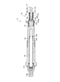
- FIG. 1 is a longitudinal sectional view of a ceramic heater type glow plug 1 for a diesel engine according to an embodiment of the present invention.
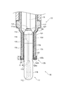
- FIG. 2 is a longitudinal sectional view of a ceramic heater type glow plug in which the vicinity of the ceramic assembly in FIG. 1 is enlarged.
- the glow plug 1 shown in FIGS. 1 and 2 includes a ceramic heater assembly 10, a housing 14, a lead bar 16, and the like.
- the cross section refers to a cut surface perpendicular to the longitudinal axis of the ceramic heater type glow plug 1
- the vertical cross section refers to a cut surface including the longitudinal axis of the ceramic heater type glow plug 1.
- the ceramic heater assembly 10 includes a ceramic heater 11, a metal outer cylinder (sheath) 12, a large-diameter lead portion 13, and the like.
- the ceramic heater 11 is a portion that is heated by energization, and a ceramic heating element 112 formed in a U shape is embedded in the ceramic heater 11 inside the ceramic insulating base 111 that constitutes the main body of the ceramic heater 11. .
- a positive electrode 114 and a negative electrode 115 are provided on both ends of the ceramic heating element 112 via metal leads 113, respectively.
- the negative electrode 115 is taken out on the outer peripheral surface of the ceramic insulating substrate 111, and a negative electrode side metallized portion 116 is formed on the outer peripheral surface of the ceramic insulating substrate 111 including the negative electrode 115.
- the outer cylinder 12 is formed of a conductive metal material.
- the outer cylinder 12 has an inner diameter that is large enough to allow the ceramic heater 11 to be inserted.
- the ceramic heater 11 and the outer cylinder 12 are joined by brazing by supplying a brazing material to the joint in a state where the negative electrode side metallized portion 116 of the ceramic heater 11 is inserted and fixed in the outer cylinder 12. . That is, the negative electrode side metallized portion 116 of the ceramic heater 11 is joined to the inner surface of the outer cylinder 12 by the brazing material and is electrically connected.
- the negative electrode side metallized part 116 is formed of, for example, a silver paste containing 30% by weight or less of copper (Cu) and 10% by weight or less of titanium (Ti) with respect to the total weight of the negative electrode side metallized part 116.
- the positive electrode 114 is taken out to the outer surface of the ceramic insulating base 111 on the rear end side opposite to the front end side where the ceramic heating element 112 is embedded.
- a positive side metallized portion 117 is formed on the rear end surface of the ceramic insulating base 111 including the positive side electrode 114.
- the positive side metallized portion 117 is joined to the tip surface 131 of the large diameter lead portion 13 by brazing or the like, and the positive side electrode 114 and the large diameter lead portion 13 are electrically connected.
- a chamfered portion 111 a is formed on the rear end surface of the ceramic insulating substrate 111.
- the distance between the ceramic insulating base 111 and the outer cylinder 12 can be increased around the joint between the ceramic insulating base 111 and the large-diameter lead portion 13. Therefore, in the case of brazing, the insulation between the brazing material and the outer cylinder 12 is enhanced, and the dielectric breakdown can be reduced.
- the outer cylinder 12 includes an element body 121, a metal layer 122 formed on the entire surface (inner surface and outer surface) of the element body 121, and a tip portion 125 on the ceramic heater side of the outer cylinder 12. And a coating layer 123 formed on the substrate.
- the thicknesses of the metal layer 122 and the coating layer 123 are shown relatively large in order to clearly describe the characteristics of the glow plug.
- the element body 121 is preferably an alloy mainly made of iron because it can withstand the brazing temperature. Particularly, since the heat resistance is high, an alloy mainly made of iron and Ni is more preferable, and stainless steel is more preferable. preferable. Further, among stainless steels, stainless steel alloys mainly composed of iron, Ni, and Cr are particularly preferable because of their high durability. In addition, it is preferable to form the element body 121 in a cylindrical shape from the viewpoint of uniformly brazing the ceramic heater and enhancing durability.
- the element body 121 has an enlarged cross-section in the middle of the axial direction, and a step-shaped enlarged diameter portion 127 is formed therein.
- this enlarged diameter portion 127 is a place where the brazing material is placed, the rear end side of the ceramic heater 11 to be inserted into the outer cylinder 12 than the negative side metallized portion 116 (opposite to the insertion end portion of the ceramic heater 11). In the direction end).
- the metal layer 122 is formed of a material having excellent conductivity and high wettability with the brazing material.
- An example of such a metal layer 122 is a metal plating layer.
- the metal plating layer include Ni (nickel) plating, and boron-based Ni plating is particularly preferable because of excellent durability.
- the thickness t 1 of the metal layer 122 is preferably 5 to 20 ⁇ m. Note that the metal layer 122 is not necessarily formed so as to cover the entire surface of the element body 121 evenly, and at least a portion in contact with the brazing material (installation of the brazing material) from the viewpoint of wettability with the brazing material. Or a connecting portion between the ceramic heater 11 and the outer cylinder 12).
- the coating layer 123 is formed of a material having low wettability with the brazing material (preferably one having lower wettability than the metal layer 122). Further, since the outer cylinder 12 is heated to a high temperature (about 800 to 900 ° C.) at the time of brazing, the coating layer 123 is preferably made of a thermally stable material.
- a thermally stable material is ceramics. Examples of ceramics include oxide-based, carbide-based, and nitride-based ceramics. Among these, oxide-based ceramics are preferable in terms of excellent heat resistance. Examples of oxide ceramics include silica, alumina, zirconia, titania, magnesia, and calcia. The above materials may be used alone or in combination.
- the coating layer 123 may be colored and may contain a pigment or a dye.
- the coating layer 123 is formed on the tip 125 of the outer cylinder 12 on the ceramic heater side. Specifically, the coating layer 123 only needs to be formed on at least one of the inner peripheral surface 125a, the end surface 125b, and the outer peripheral surface 125c in the distal end portion 125 of the outer cylinder 12. In FIG. 2, the coating layer 123 is formed on all surfaces of the inner peripheral surface 125a, the end surface 125b, and the outer peripheral surface 125c at the distal end portion 125 of the outer cylinder 12. For example, the coating layer 123 may be formed on the inner peripheral surface 125a of the distal end portion 125 of the outer cylinder 12 when the purpose is to reduce the amount of brazing material used.
- the length L along the axis of the outer cylinder 12 of the coating layer 123 is 0.5 to 1.0 mm. It is preferable that the coating layer 123 may be formed on the outer peripheral surface 125 c of the distal end portion 125 of the outer cylinder 12 when it is intended to be used as an identification mark of the ceramic heater type glow plug 1.
- the coating layer 123 is formed on the outer peripheral surface 125c of the distal end portion 125 of the outer cylinder 12 when it is intended to be used as an identification mark of the ceramic heater type glow plug 1.
- the length L along the axis of the outer cylinder 12 of the coating layer 123 is 0.5 to 1.0 mm.
- the film thickness t 2 of the coating layer 123 is preferably 2 to 15 ⁇ m.
- the large-diameter lead 13 is electrically connected to the positive electrode 114 of the ceramic heater 11.
- the large-diameter lead portion 13 flows at a high temperature and a large current (for example, 4 to 30 amperes) when the glow plug 1 is operated. Therefore, if the diameter is too small, for example, less than 1 mm, self-heating is added and the time is short. May oxidize. Therefore, the large-diameter lead portion 13 is formed as a lead rod having a relatively large diameter and having a cross-sectional area of 20% or more of the cross-sectional area of the ceramic insulating base 111, for example.
- the cross-sectional area of the large-diameter lead portion 13 is preferably 40% or less of the cross-sectional area of the ceramic insulating base 111, for example. Further, the length of the large-diameter lead portion 13 is preferably set to be twice or more the diameter of the large-diameter lead portion 13.
- the large-diameter lead portion 13 is made of a material having lower rigidity and higher electric conductivity than the lead rod 16 as an external connection terminal. Examples of such a material include copper (Cu), aluminum (Al), and alloys thereof. Alternatively, an iron alloy or cast iron having low rigidity and high electrical conductivity can be used.
- the large-diameter lead portion 13 may be subjected to nickel (Ni) plating or the like in order to improve heat resistance, and may be covered with silver (Ag) in order to improve oxidation resistance.
- the housing 14 is a fitting for attaching to a cylinder head of an engine (not shown), and accommodates the outer cylinder 12 and the large-diameter lead portion 13.
- the housing 14 is formed in a cylindrical shape, for example, and the ceramic heater assembly 10 configured as described above is fixed by brazing or the like.
- the other end of the outer cylinder 12 is fixed to the inside of the housing 14 by brazing or the like.
- the outer cylinder 12 is brazed to the inside of a metal tube or the like (not shown). It is also possible to fix the metal tube and the member constituting the housing main body, and form the housing 14 integrally.
- the lead bar 16 is accommodated in the housing 14 and fixed by a filler 173 and a seal ring 174 made of resin or low melting point glass filled between the housing 14. Further, the lead rod 16 is joined to the rear end portion of the large-diameter lead portion 13 by welding. The lead rod 16 is held by the insulator 171 on the rear end side of the housing 14, and the rear end portion is exposed to the outside of the housing 14 and connected to the round pin 172.
- a ceramic heater 11 and an outer cylinder 12 are prepared.
- the negative electrode side metallized portion 116 is formed on the outer peripheral surface thereof.
- a metal layer 122 and a coating layer 123 are formed on the outer cylinder 12.
- the metal layer 122 can be formed, for example, by performing metal plating or the like on the surface of the element body 121. As a plating method, a known method can be used.
- the coating layer 123 can be formed using, for example, a coating solution.
- a coating solution for example, a paint mainly composed of ceramics can be used.
- the coating material mainly composed of ceramics for example, KB coat, Fuji Gamma manufactured by Gamma Chemical Co., Ltd. are suitable.
- the application method include dip coating, spray coating, brush coating, flow coating, and transfer. Among these, dip coating is preferable from the viewpoint of ease of work.
- the concentration and viscosity of the coating solution are adjusted as appropriate according to the application method and the like. Further, the coating amount, depending on the film thickness t 2, etc. of the coating layer 123 to be formed may be appropriately adjusted, when increasing the thickness t 2 is that for recoating in several preferable. This is because if a large amount of coating solution is applied at once, the coating layer 123 after drying is cracked and easily peeled off.
- the ceramic heater 11 is inserted into the inner hole 120 of the outer cylinder 12.
- the ceramic heater 11 is inserted into the outer cylinder 12 until the enlarged diameter portion 127 of the outer cylinder 12 and the positive side metallized portion 117 of the ceramic heater 11 are in a predetermined positional relationship (see FIG. 3B).
- a brazing material 175 is placed on the enlarged diameter portion 127 of the outer cylinder 12. Further, the front end surface 131 of the large-diameter lead portion 13 is placed on the positive side metallized portion 117 of the ceramic heater 11. At this time, a brazing material 176 different from the brazing material 175 placed on the enlarged diameter portion 127 is placed between the positive electrode side metallized portion 117 and the large diameter lead portion 13. Thereafter, the assembly is heated to 800 to 900 ° C. in a state where the outer cylinder 12, the ceramic heater 11, and the large diameter lead portion 13 are temporarily assembled. Thereby, the ceramic heater 11 and the outer cylinder 12, the ceramic heater 11 and the large diameter lead part 13 are brazed simultaneously, respectively.
- the lead rod 16 and the large-diameter lead portion 13 are joined and fixed by welding (for example, spot welding).
- the housing 14 is lowered until the front end surface 141 of the housing 14 comes into contact with the rear end surface 129 of the protruding portion 128 of the outer cylinder 12. With the contact in this manner, the front end surface 141 of the housing 14 and the rear end surface 129 of the protruding portion 128 of the outer cylinder 12 are welded.
- the housing 14 and the outer cylinder 12 may be fixed by brazing the inner peripheral surface 142 of the housing 14 and the outer peripheral surface 12c of the outer cylinder 12.
- a seal ring 174 is inserted between the housing 14 and the lead bar 16.
- a filler 173 made of resin or low-melting glass is filled between the lead bar 16 and the housing 14.
- the brazing material can easily move on the inner peripheral surface 12a of the outer cylinder 12 during brazing.
- the brazing material can be satisfactorily supplied to the joint portion of the heater 11 with the negative electrode side metallized portion 116.
- the flow of the brazing material can be improved by using Ni (nickel) -B (boron) alloy plating as the metal layer 122. As a result, the durability and conductivity of the joint are improved.
- the brazing material can be prevented from spreading to the outer peripheral surface 12c of the outer cylinder 12 during brazing, and the outer cylinder 12 and the ceramic heater can be prevented.
- the brazing material can be stably supplied to the negative electrode side metallized portion 116 and the joint portion.
- the usage amount of the brazing material which is an expensive material can be controlled to an appropriate amount, an increase in manufacturing cost can be prevented.
- the coating layer 123 can be formed by a simple method while keeping the metal layer 122 once formed, and the spreading of the brazing material can be prevented by the coating layer 123. This eliminates the need for a conventional outer cylinder processing and cleaning step, and simplifies the process.
- the coating layer 123 is formed on the inner peripheral surface 125a of the distal end portion 125 of the outer cylinder 12, the amount of brazing material used can be minimized.
- the coating layer 123 is formed on the outer peripheral surface 125c of the distal end portion 125 of the outer cylinder 12, and the coating layer 123 has a color different from that of the outer cylinder 12 and the metal layer 122, thereby using the coating layer 123 as an identification mark. You can also. Since the appearance of the glow plug 1 is very similar, conventionally, there is a possibility that components are mistaken during assembly or the insertion direction is wrong. However, the coating layer 123 is replaced with the outer cylinder 12 and the metal layer 122. By using different colors, it is possible to prevent such erroneous assembly.
- the glow plug described above shows one aspect of the present invention and does not limit the present invention, and each embodiment can be arbitrarily changed within the scope of the present invention.
- the coating layer 123 is formed over the inner surface 125a, the end surface 125b, and the outer surface 125c of the tip portion of the outer cylinder 12, but it may be formed on any one surface.
Landscapes
- Engineering & Computer Science (AREA)
- Chemical & Material Sciences (AREA)
- Combustion & Propulsion (AREA)
- Mechanical Engineering (AREA)
- General Engineering & Computer Science (AREA)
- Resistance Heating (AREA)
Abstract
L'objet de l'invention est de réduire le coût de production en simplifiant le processus de production par rapport aux processus classiques. Une bougie de préchauffage (1) du type à élément chauffant en céramique qui est pourvue : d'un élément chauffant en céramique (11) ; et d'un cylindre extérieur (12) qui est constitué d'un métal, et a une partie d'extrémité à laquelle est relié l'élément chauffant en céramique au moyen d'un matériau d'apport de brasage (175) et l'autre partie d'extrémité qui est fixée à un boîtier (14). Le cylindre externe a une couche de métal (122) sur la surface, ladite couche de métal (122) améliorant la mouillabilité du matériau d'apport de brasage par rapport au matériau du cylindre extérieur. Une couche de revêtement (123) est formée sur la surface de la couche de métal au niveau d'une partie d'extrémité du cylindre extérieur, ladite couche de revêtement (123) abaissant la mouillabilité du matériau d'apport de brasage par rapport à la couche de métal.
Priority Applications (1)
| Application Number | Priority Date | Filing Date | Title |
|---|---|---|---|
| JP2017507587A JP6395239B2 (ja) | 2015-03-23 | 2016-02-11 | セラミックスヒータ型グロープラグ |
Applications Claiming Priority (2)
| Application Number | Priority Date | Filing Date | Title |
|---|---|---|---|
| JP2015-059948 | 2015-03-23 | ||
| JP2015059948 | 2015-03-23 |
Publications (1)
| Publication Number | Publication Date |
|---|---|
| WO2016152302A1 true WO2016152302A1 (fr) | 2016-09-29 |
Family
ID=56977967
Family Applications (1)
| Application Number | Title | Priority Date | Filing Date |
|---|---|---|---|
| PCT/JP2016/054040 Ceased WO2016152302A1 (fr) | 2015-03-23 | 2016-02-11 | Bougie de préchauffage du type à élément chauffant en céramique |
Country Status (2)
| Country | Link |
|---|---|
| JP (1) | JP6395239B2 (fr) |
| WO (1) | WO2016152302A1 (fr) |
Citations (3)
| Publication number | Priority date | Publication date | Assignee | Title |
|---|---|---|---|---|
| JPS6172932A (ja) * | 1984-09-14 | 1986-04-15 | Ngk Spark Plug Co Ltd | セラミツクグロ−プラグ |
| JP2005315447A (ja) * | 2004-04-27 | 2005-11-10 | Kyocera Corp | セラミックヒーターおよびグロープラグ |
| WO2014083913A1 (fr) * | 2012-11-29 | 2014-06-05 | ボッシュ株式会社 | Bougie de préchauffage d'élément chauffant en céramique et son procédé de fabrication |
Family Cites Families (1)
| Publication number | Priority date | Publication date | Assignee | Title |
|---|---|---|---|---|
| WO2014122958A1 (fr) * | 2013-02-08 | 2014-08-14 | ボッシュ株式会社 | Bougie de départ type corps de capteur de pression, et procédé de fabrication de celle-ci |
-
2016
- 2016-02-11 JP JP2017507587A patent/JP6395239B2/ja active Active
- 2016-02-11 WO PCT/JP2016/054040 patent/WO2016152302A1/fr not_active Ceased
Patent Citations (3)
| Publication number | Priority date | Publication date | Assignee | Title |
|---|---|---|---|---|
| JPS6172932A (ja) * | 1984-09-14 | 1986-04-15 | Ngk Spark Plug Co Ltd | セラミツクグロ−プラグ |
| JP2005315447A (ja) * | 2004-04-27 | 2005-11-10 | Kyocera Corp | セラミックヒーターおよびグロープラグ |
| WO2014083913A1 (fr) * | 2012-11-29 | 2014-06-05 | ボッシュ株式会社 | Bougie de préchauffage d'élément chauffant en céramique et son procédé de fabrication |
Also Published As
| Publication number | Publication date |
|---|---|
| JP6395239B2 (ja) | 2018-09-26 |
| JPWO2016152302A1 (ja) | 2017-10-19 |
Similar Documents
| Publication | Publication Date | Title |
|---|---|---|
| JP7525569B2 (ja) | 熱交換ユニットおよびこれを備えた洗浄装置 | |
| JPH10205753A (ja) | セラミックグロープラグ | |
| JP6317469B2 (ja) | ヒータおよびこれを用いた流体加熱装置 | |
| EP3135998B1 (fr) | Procédé de fabrication de bougie de préchauffage du type à élément chauffant en céramique et bougie de préchauffage du type à élément chauffant en céramique | |
| JP5243498B2 (ja) | セラミックヒータ及びそれを備えたガスセンサ | |
| JP6005175B2 (ja) | セラミックスヒータ型グロープラグ及びその製造方法 | |
| JP6395239B2 (ja) | セラミックスヒータ型グロープラグ | |
| JP6245716B2 (ja) | セラミックスヒータ型グロープラグの製造方法及びセラミックスヒータ型グロープラグ | |
| JP2017182910A (ja) | ヒータ | |
| JP5868276B2 (ja) | セラミックヒータ、ガスセンサおよびセラミックヒータの製造方法 | |
| JP6313155B2 (ja) | ヒータ | |
| US10113744B2 (en) | Ceramic heater-type glow plug | |
| JP6270185B2 (ja) | セラミックスヒータ型グロープラグの製造方法及びセラミックスヒータ型グロープラグ | |
| JP2009293989A (ja) | セラミックヒータ及びガスセンサ | |
| JP6835946B2 (ja) | ヒータ | |
| JPWO2015146554A1 (ja) | セラミックスヒータ型グロープラグ | |
| JP6665495B2 (ja) | セラミックヒータ | |
| JP2009252389A (ja) | セラミックヒータ及びガスセンサ | |
| CN105744658B (zh) | 陶瓷加热器以及传感器 | |
| JP2018097985A (ja) | ヒーター | |
| JP2012068217A (ja) | ガスセンサ | |
| US20180112874A1 (en) | Glow plug | |
| JPWO2020175564A1 (ja) | 熱交換ユニットおよびこれを備えた洗浄装置 | |
| KR200442507Y1 (ko) | 고열형 전기 납땜 인두 |
Legal Events
| Date | Code | Title | Description |
|---|---|---|---|
| 121 | Ep: the epo has been informed by wipo that ep was designated in this application |
Ref document number: 16768205 Country of ref document: EP Kind code of ref document: A1 |
|
| ENP | Entry into the national phase |
Ref document number: 2017507587 Country of ref document: JP Kind code of ref document: A |
|
| NENP | Non-entry into the national phase |
Ref country code: DE |
|
| 122 | Ep: pct application non-entry in european phase |
Ref document number: 16768205 Country of ref document: EP Kind code of ref document: A1 |