WO2016152802A1 - 無線端末、通信方法及びプログラム - Google Patents
無線端末、通信方法及びプログラム Download PDFInfo
- Publication number
- WO2016152802A1 WO2016152802A1 PCT/JP2016/058788 JP2016058788W WO2016152802A1 WO 2016152802 A1 WO2016152802 A1 WO 2016152802A1 JP 2016058788 W JP2016058788 W JP 2016058788W WO 2016152802 A1 WO2016152802 A1 WO 2016152802A1
- Authority
- WO
- WIPO (PCT)
- Prior art keywords
- period
- cycle
- reception
- reception operation
- data
- Prior art date
- Legal status (The legal status is an assumption and is not a legal conclusion. Google has not performed a legal analysis and makes no representation as to the accuracy of the status listed.)
- Ceased
Links
Images






Classifications
-
- H—ELECTRICITY
- H04—ELECTRIC COMMUNICATION TECHNIQUE
- H04W—WIRELESS COMMUNICATION NETWORKS
- H04W52/00—Power management, e.g. Transmission Power Control [TPC] or power classes
- H04W52/02—Power saving arrangements
-
- Y—GENERAL TAGGING OF NEW TECHNOLOGICAL DEVELOPMENTS; GENERAL TAGGING OF CROSS-SECTIONAL TECHNOLOGIES SPANNING OVER SEVERAL SECTIONS OF THE IPC; TECHNICAL SUBJECTS COVERED BY FORMER USPC CROSS-REFERENCE ART COLLECTIONS [XRACs] AND DIGESTS
- Y02—TECHNOLOGIES OR APPLICATIONS FOR MITIGATION OR ADAPTATION AGAINST CLIMATE CHANGE
- Y02D—CLIMATE CHANGE MITIGATION TECHNOLOGIES IN INFORMATION AND COMMUNICATION TECHNOLOGIES [ICT], I.E. INFORMATION AND COMMUNICATION TECHNOLOGIES AIMING AT THE REDUCTION OF THEIR OWN ENERGY USE
- Y02D30/00—Reducing energy consumption in communication networks
- Y02D30/70—Reducing energy consumption in communication networks in wireless communication networks
Definitions
- the present invention relates to a wireless terminal, a communication method, and a program.
- 3GPP LTE Long Term Evolution
- DRX discontinuous reception
- References 1, 2 a period constituted by a reception period (On-Duration) called DRX cycle and a subsequent non-reception period (Opportunity for DRX) is defined, and DRX is realized by repeating these periods.
- the wireless terminal needs to always receive a downlink control channel (PDCCH: Physical Downlink Control Channel) in On-duration, and may not receive PDCCH in Opportunity for DRX. If the wireless terminal fails to receive data during the On-Duration period and the data is retransmitted after the On-Duration period, the period for receiving the PDCCH is extended.
- PDCCH Physical Downlink Control Channel
- the period during which the radio terminal in DRX operation receives the PDCCH is called Active Time
- On-Duration is the minimum value of Active Time.
- two DRX states (levels) of “ShortDRX” and “LongDRX” having different lengths of Opportunity for DRX can be set for each wireless terminal.
- DRX state control DRX state control
- a timer drxShortCycleTimer
- the DRX state (level) suitable for the data reception frequency of the wireless terminal can be set, and the power consumption of the wireless terminal can be reduced.
- 3GPP TS36.300v900 Internet ⁇ URL> http: www.3gpp.org/ftp/Specs/html-info/36300.html
- 3GPP TS36.321v860 Internet ⁇ URL> http: www.3gpp.org/ftp/Specs/html-info/36321.html
- the present invention has been invented in view of the above problems, and it is an object of the present invention to provide a wireless terminal capable of realizing power saving of the wireless terminal while rapidly receiving a signal from the network side.
- One aspect of the present invention is a communication processing unit that transmits and receives data, and the non-reception of the second period when the communication processing unit is performing intermittent reception of a second period that is longer than the first period.
- the wireless terminal includes a communication control unit that starts a reception operation at a predetermined timing in a period and causes the communication processing unit to perform a predetermined number of reception operations.
- the data reception operation is started at a predetermined timing in the non-reception period of the second cycle.
- communication processing means for transmitting and receiving data is operating at a predetermined timing in the non-reception period of the second cycle during the operation of intermittent reception of the second cycle having a cycle longer than the first cycle.
- FIG. 1 is a block diagram of the present invention.
- FIG. 2 is a diagram illustrating an example of a schematic configuration of the wireless communication system according to the embodiment of this invention.
- FIG. 3 is a block diagram of the radio terminal (UE) 1 in the radio communication system of the present embodiment.
- FIG. 4 is a block diagram of the radio base station (eNB) 20 of the present embodiment.
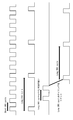
- FIG. 5 is a diagram illustrating an operation of discontinuous reception (DRX) in the wireless communication system according to the present embodiment.
- FIG. 6 is a diagram illustrating a case in which two Wake ups are provided at a constant cycle and performed at every cycle interval of LongDRX within a Long DRX Sleep period.
- FIG. 7 is a diagram illustrating a case where two Wake ups are provided at a constant cycle and performed at every cycle interval of the Long DRX within the Long DRX Sleep period, at a Wake up timing of the Short DRX.
- FIG. 8 is a diagram illustrating a case where a Wake up is provided once at a timing near the center of the Long DRX.
- FIG. 9 is a diagram illustrating a case in which the LongDRX timing is reset after Wake up.
- FIG. 10 is a flowchart of the operation after Wake up performed during the Sleep period of LongDRX.
- FIG. 11 is a diagram illustrating a case where data is received during ShortDRX and transition is made from LongDRX to ShortDRX.
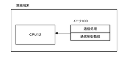
- FIG. 12 is a diagram illustrating another aspect of the radio terminal (UE) 1 in the radio communication system according to the present embodiment.
- FIG. 1 is a block diagram of the present invention.
- the present invention includes a communication processing unit 1 that transmits and receives data, and a second period when the communication processing unit 1 performs an intermittent reception operation of a second period that is longer than the first period.
- the wireless terminal includes a communication control unit 2 that starts reception at a predetermined timing in the non-reception period and causes the communication processing unit 1 to receive an arbitrary number of times.
- the wireless terminal when the wireless terminal is in an intermittent reception operation in the second period that is long between the period in which data can be received (for example, Active Time) and the period (for example, , During the operation of Long DRX), the reception operation is performed for a certain period of time at a predetermined timing of the non-reception period (for example, Opportunity for DRX), with a period shorter than the second period.
- the non-reception period for example, Opportunity for DRX
- ShortDRX as a representative of the first cycle
- LongDRX as a representative of the second cycle
- the predetermined timing of the non-reception period of the second cycle may be an arbitrary timing or a predetermined timing.
- Examples of the predetermined timing include the timing of the synchronized first cycle and the timing at which the non-reception period of the second cycle is constant before and after the timing (for example, the non-reception period of the second cycle). Timing near the center of the).
- the reception operation may be performed only once in the non-reception period of the second cycle, or may be performed multiple times. Also good. However, when it is performed a plurality of times, the reception operation is performed at a cycle shorter than the second cycle. Furthermore, when performing a plurality of times, it is preferable that the non-reception period of the second cycle is constant before and after the reception operation, for example, twice during the non-reception period of the second cycle. When the reception operation is performed, the reception operation is performed with a period that becomes active at a timing near one third or two thirds of the non-reception period of the second period. Thereby, the non-reception period of the timing before and after becomes constant.
- the reception operation may be performed only in the non-reception period of the first cycle in the second cycle, or the non-reception period of the second cycle.
- the reception operation may be performed at regular intervals.
- the intermittent reception operation may be performed while maintaining the timing of the second cycle, or the timing of the second cycle is reset, The intermittent reception operation of the second cycle may be performed at a proper timing. Furthermore, when data is received during the reception operation in the non-reception period of the second cycle, the intermittent reception operation may be performed by transitioning to the first cycle with a shorter cycle.
- the second cycle takes into account the past received data performance (for example, the amount of data and the presence or absence of the most recent data reception). It may be determined whether or not to perform the reception operation during the non-reception period.
- the above-described communication control unit 2 controls the reception operation performed during the non-reception period of the second cycle (the start timing and the number of reception operations and the determination thereof) and the reception operation during the non-reception period of the second cycle. Subsequent control or the like may be preset in the communication control unit 2 or may be an instruction from the network side such as a base station.
- the types of wireless terminals are not limited. For example, not only wireless terminals (UE: User Equipment) and PCs typified by smartphones and mobile phones, but also MTC (Machine Type Communication) terminals, M2M (Machine- To-Machine) terminals or devices or sensors used in IoT (Internet of Things) are also included.
- power saving of a wireless terminal can be realized while quickly receiving a paging signal from the network side.
- 3GPP LTE Long Term Evolution
- cellular system a wireless communication system
- FIG. 2 is a diagram showing an example of a schematic configuration of the wireless communication system according to the embodiment of the present invention.
- the radio communication system includes a radio terminal (UE: User Equipment) UE10 and a radio base station (eNB: evolved NodeB) eNB20.
- UE User Equipment
- eNB evolved NodeB
- the UE 10 has completed connection establishment (RRC Connection) for communicating with the eNB 20.
- RRC Connection connection establishment
- CC1 to CC3 are assigned as component carriers (CC: Component Carrier) capable of carrier aggregation (CA), and CC1 to CC3 are already in a state where data can be received simultaneously.
- CA carrier aggregation
- CC1 to CC3 may be either continuous or discontinuous, and the frequency bands may be the same or different. Further, the eNB 20 notifies the UE 10 of a parameter of intermittent reception (DRX: Discontinuous Reception), and the UE 10 performs necessary settings (for example, setting of an expiration value of a DRX related timer) according to the parameters. At this time, the DRX parameters are common in CC1 to CC3.
- DRX Discontinuous Reception
- FIG. 3 is a block diagram of the radio terminal (UE) 10 in the radio communication system of the present embodiment.
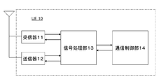
- the UE 10 includes a receiver 11, a transmitter 12, a signal processing unit 13, and a communication control unit 14.
- the receiver 11 and the transmitter 12 are parts that receive and transmit radio signals to and from the eNB 20, respectively.
- the signal processing unit 13 is a part that generates a radio signal for transmitting certain information to the eNB 20 and restores the original information from the received radio signal.
- the communication control unit 14 is a part that instructs the signal processing unit 13 to generate a transmission signal, restore information, and the like, and the DRX control of the UE is also managed by the communication control unit 14.
- FIG. 4 is a block diagram of the radio base station (eNB) 20 of the present embodiment.
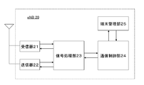
- the eNB 20 includes a receiver 21, a transmitter 22, a signal processing unit 23, a communication control unit 24, and a terminal management unit 25.
- the receiver 21, transmitter 22, signal processing unit 23, and communication control unit 24 basically have the same functions as those of the UE 10.
- the terminal management part 25 it manages individually with respect to each of several UE.
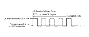
- FIG. 5 is a diagram illustrating an operation of discontinuous reception (DRX) in the wireless communication system according to the present embodiment.
- the DRX cycle which is a period of intermittent reception, must receive the PDCCH and the period during which the downlink control channel PDCCH (Physical Downlink Control Channel) must be received continuously (On-Duration). It is composed of a period (Opportunity for DRX). The former is also called a Wake up period, and the latter is also called a Sleep period. The latter may be a period in which no PDCCH is received or a period in which no PDCCH should be received.
- PDCCH Physical Downlink Control Channel
- the data is transmitted by PDSCH (Physical Downlink Shared Channel), and PDSCH scheduling information is included in the PDCCH. Therefore, after receiving the PDCCH and detecting the scheduling information, the designated data can be received.
- PDSCH Physical Downlink Shared Channel
- ShortDRX cycle there are two types of DRX cycle: ShortDRX and LongDRX.
- ShortDRX and LongDRX have the same On-Duration, the lengths of periods in which PDCCHs other than On-Duration need not be received are different, and Short-DRX has a shorter On-Duration interval.
- Long DRX is an integral multiple of Short DRX.
- the length of the On-Duration and DRX cycle can be set, for example, from 10 ms to 1 ms to 200 ms, and the DRX cycle can be set from 2 ms (ShortDRX minimum) to 2560 ms (LongDRX maximum). Dozens of settings are possible for ShortDRX and LongDRX.
- DRX has two DRX states called ShortDRX and LongDRX.
- ShortDRX corresponds to the first period in the present invention
- LongDRX corresponds to the second period in the present invention.
- ShortDRX ShortDRX first, and if there is no data received for a certain period, it transitions to LongDRX.
- the communication control unit 14 performs control so that a Wake up period is provided at a predetermined timing of the Long DRX Sleep period and at a period shorter than the Long DRX period.
- CA carrier aggregation
- the communication control unit 14 is the timing and the number of times of Wake up during the Sleep period of LongDRX, the following control is conceivable.
- Controlling to Wake Up Randomly During Long DRX Sleep Period there is a method of controlling to wake up at random timing within the Sleep period of Long DRX.
- the number of Wake ups may be one time within the Long DRX Sleep period or a plurality of times in a predetermined cycle.
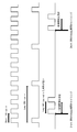
- FIG. 6 shows a case where two Wake ups are provided at a fixed cycle and at a certain cycle within the Long DRX Sleep period, and this operation is performed at each cycle interval of the Long DRX.
- FIG. 7 shows a case where two Wake ups are provided at a constant cycle at a Short DRX Wake up timing within a Long DRX Sleep period, and this operation is performed at each cycle interval of the Long DRX. .
- FIG. 8 is an example in which a Wake up is provided once at the timing near the center of the Long DRX cycle, and shows a case where the Sleep period of the Long DRX is constant before and after the Wake up period.
- the above timing operation is not necessarily limited to one, and may be controlled by combining these methods.
- FIG. 9 shows a case where the LongDRX timing is reset after the Wake up and the LongDRX is continued in the LongDRX cycle.
- the subsequent operation may be determined depending on whether or not data is received during Wake up performed during the Sleep period of LongDRX.
- FIG. 10 is a flowchart of the operation after Wake up performed during the Long DRX Sleep period described above.
- the ShortDRX is operated a predetermined number of times at the ShortDRX Wake up timing within the LongDRX Sleep period will be described as an example.
- ShortDRX is operated during the Sleep period of LongDRX. It is determined whether data is received during this ShortDRX. When data is received, the transition is from Long DRX to Short DRX. On the other hand, when data is not received, the operation of the Long DRX is continued at the timing of the old Long DRX or the new Long DRX.
- FIG. 11 is a diagram showing a case where the ShortDRX is operated during the Sleep period of the LongDRX, data is received during the ShortDRX, and the transition is made from the LongDRX to the ShortDRX.
- the past received data performance (for example, the amount of data and the presence or absence of the most recent data reception) may be considered. For example, if the amount of data received at the time of ShortDRX before transitioning to LongDRX exceeds a predetermined threshold, Wake up is performed during the Sleep period of LongDRX. In addition, when data is received during the short DRX of the last several cycles before the transition to LongDRX, Wake up is performed during the Sleep period of LongDRX.
- each unit is configured by hardware, but may be configured by a program that causes an information processing device (CPU) to perform the above-described operation processing.
- CPU information processing device
- functions and operations similar to those of the above-described embodiment are realized by a processor that operates according to a program stored in the program memory.
- FIG. 12 it can be realized by a computer system including a memory 100 and a CPU 101.
- the memory 100 stores a program for performing processing corresponding to the signal processing unit 13 and processing corresponding to the communication control unit 14 described above.
- the functions of the signal processing unit 13 and the communication control unit 14 are realized by the CPU 101 executing the program stored in the memory 100.
- [Appendix 1] Communication processing means for transmitting and receiving data; and During the operation of the intermittent reception of the second cycle having a period longer than the first cycle, the communication processing unit starts the reception operation at a predetermined timing of the non-reception period of the second cycle, and receives a predetermined number of times. And a communication control unit that causes the communication processing unit to perform an operation.
- the communication control means causes the communication processing means to perform the data reception operation for a certain period of time before and after the period of the data reception operation, at a timing such that the non-reception period of the second period becomes equal.
- the wireless terminal according to any one of appendix 3 to.
- the communication control means maintains the timing of the second cycle and performs the intermittent reception operation after the data reception operation performed during the non-reception period of the second cycle by the communication processing means.
- the wireless terminal according to any one of appendix 1 to appendix 5, which is to be performed.
- the communication control unit resets the timing of the second cycle and performs the second cycle at a new timing after the data reception operation performed during the non-reception period of the second cycle by the communication processing unit.
- the wireless terminal according to any one of appendix 1 to appendix 5, which causes the communication processing means to perform an intermittent reception operation.
- Appendix 8 The communication control means, based on the past data transmission / reception results, at a predetermined timing of the non-reception period of the second cycle while the communication processing means is in the intermittent reception operation of the second cycle.
- the wireless terminal according to any one of appendix 1 to appendix 7, which determines whether to perform a data reception operation for a certain period with a cycle shorter than the cycle of 2.
- Appendix 10 The communication method according to appendix 9, wherein a data reception operation is started at the timing of the first cycle in the non-reception period of the second cycle.
- Appendix 12 The communication method according to any one of appendix 9 to appendix 11, wherein the data reception operation is performed for a certain period of time before and after the period of the data reception operation, at a timing such that the non-reception period of the second period is equal. .
- Appendix 16 Based on the past data transmission / reception results, during the intermittent reception operation of the second cycle, at a predetermined timing of the non-reception period of the second cycle, for a certain period of time shorter than the second cycle, 16.
- the communication method according to any one of appendix 9 to appendix 15, which determines whether to perform a data reception operation.
- the communication processing means for transmitting and receiving data starts the data reception operation at a predetermined timing in the non-reception period of the second cycle during the intermittent reception operation of the second cycle having a cycle longer than the first cycle.
- the processor is Communication processing to send and receive data; During the intermittent reception operation of the second cycle having a period longer than the first cycle, the reception operation is started at a predetermined timing in the non-reception period of the second cycle, and a predetermined number of reception operations are performed.
- a wireless terminal that executes communication control processing for controlling the communication processing.
- Appendix 19 The wireless terminal according to appendix 18, wherein the communication control process controls the communication process so that a data reception operation is started at a timing of the first period in a non-reception period of the second period.
- Appendix 20 The wireless terminal according to appendix 18 or appendix 19, wherein the communication control process controls the communication process so that a data reception operation is performed for a certain period in the first cycle.
- the communication control process controls the communication process so that the data reception operation is performed for a certain period of time before and after the period of the data reception operation, at a timing such that the non-reception period of the second period becomes equal.
- the wireless terminal according to any one of appendix 18 to appendix 20.
- the communication control process is configured to perform the intermittent reception operation while maintaining the timing of the second period after the data reception operation performed during the non-reception period of the second period by the communication process.
- the wireless terminal according to any one of appendix 18 to appendix 22, which controls communication processing.
- the communication control process is based on the past data transmission / reception results, and the communication process is performed at a predetermined timing in the non-reception period of the second period during the intermittent reception operation of the second period. 25.
- the wireless terminal according to any one of appendix 18 to appendix 24, which determines whether to perform a data reception operation for a certain period with a cycle shorter than the cycle of 2.
- Communication Processing Unit 1 Communication Processing Unit 2 Communication Control Unit 10 UE 20 eNB 11 Receiver 12 Transmitter 13 Signal Processor 14 Communication Controller 21 Receiver 22 Transmitter 23 Signal Processor 24 Communication Controller 25 Terminal Manager 100 Memory 101 CPU
Landscapes
- Engineering & Computer Science (AREA)
- Computer Networks & Wireless Communication (AREA)
- Signal Processing (AREA)
- Mobile Radio Communication Systems (AREA)
Abstract
本発明は、データの送受信を行う通信処理手段と、通信処理手段が第1の周期よりも長い周期の第2の周期の間欠受信の動作中、第2の周期の非受信期間の所定のタイミングで受信動作を開始し、所定の回数の受信動作を、前記通信処理手段に行わせる通信制御手段とを有する無線端末である。
Description
本発明は、無線端末、通信方法及びプログラムに関する。
次世代のセルラシステムの1つである3GPP LTE(Long Term Evolution)では、無線端末の消費電力の削減のため、無線端末の間欠受信(DRX:Discontinuous Reception)の機能がサポートされている(非特許文献1、2)。LTEでは、DRX cycleと呼ばれる受信期間(On-Duration)とそれに続く非受信期間(Opportunity for DRX)とから構成される期間が定義され、これらの期間を繰り返すことでDRXを実現する。
無線端末は、On-durationでは下り制御チャネル(PDCCH:Physical Downlink Control Channel)を常に受信する必要があり、Opportunity for DRXではPDCCHを受信しなくてよい。なお、無線端末がOn-Duration期間中にデータ受信に失敗し、On-Duration期間以降に当該データが再送される場合には、PDCCHを受信する期間を延長する。
ここで、DRX動作中の無線端末がPDCCHを受信する期間をActive Timeと呼び、On-DurationはActive Timeの最小値である。さらに無線端末毎に、Opportunity for DRXの長さが異なる「ShortDRX」と「LongDRX」という2つのDRX状態(レベル)が設定可能である。LTEでは、ShortDRX状態の無線端末が一定期間データ受信を行わなかった場合、LongDRX状態に遷移するDRX状態制御(DRX state control)を行う。また、ShortDRXからLongDRXに状態遷移する判定に、タイマー(drxShortCycleTimer)を用いる。これにより、無線端末のデータ受信頻度に適したDRX状態(レベル)を設定でき、無線端末の消費電力の削減が可能になる。
3GPP TS36.300v900(インターネット<URL>http:www.3gpp.org/ftp/Specs/html-info/36300.htm)
3GPP TS36.321v860(インターネット<URL>http:www.3gpp.org/ftp/Specs/html-info/36321.htm)
しかし、LongDRXのように、Active TimeとActive Timeとの間が長い間欠受信の場合、その期間中にネットワーク側からのページング信号が到着している場合でも、Active Timeになるまで、無線端末がページング信号を受信できないという課題があった。
そこで、本発明は上記課題に鑑みて発明されたものであって、ネットワーク側からの信号を迅速に受信しながら、無線端末の省電力を実現することができる無線端末を提供することにある。
本発明の一態様は、データの送受信を行う通信処理手段と、前記通信処理手段が第1の周期よりも長い周期の第2の周期の間欠受信の動作中、前記第2の周期の非受信期間の所定のタイミングで受信動作を開始し、所定の回数の受信動作を前記通信処理手段に行わせる通信制御手段とを有する無線端末である。
本発明の一態様は、第1の周期よりも長い周期の第2の周期の間欠受信の動作中、前記第2の周期の非受信期間の所定のタイミングで、データの受信動作を開始し、所定の回数の受信動作を行う通信方法である。
本発明の一態様は、データの送受信を行う通信処理手段が第1の周期よりも長い周期の第2の周期の間欠受信の動作中、前記第2の周期の非受信期間の所定のタイミングで、データの受信動作を開始し、所定の回数の受信動作を前記通信処理手段に行わせる通信制御処理をコンピュータに実行させるプログラムである。
本発明によれば、ネットワーク側からの信号を迅速に受信しながら、無線端末の省電力を実現できる。
本発明の概要を説明する。図1は本発明のブロック図である。
本発明は、図1に示す如く、データの送受信を行う通信処理部1と、通信処理部1が第1の周期よりも長い周期の第2の周期の間欠受信の動作中、第2の周期の非受信期間の所定のタイミングで受信を開始し、任意の回数の受信を通信処理部1に行わせる通信制御部2とを有する無線端末である。
別の言い方をすると、本発明は、データを受信することができる期間(例えば、Active Time)と期間との間が長い第2の周期で、無線端末が間欠受信の動作しているとき(例えば、LongDRXの動作中)、その非受信期間(例えば、Opportunity for DRX)の所定のタイミングで、第2の周期よりも短い周期で、一定期間、受信動作を行うものである。
ここで、第1の周期の代表的なものとして、ShortDRXがあり、第2の周期の代表的なものとして、LongDRXがある。
また、第2の周期の非受信期間の所定のタイミングとは、任意のタイミングでも、予め定められたタイミングでも良い。予め定められたタイミングの例としては、同期している第1の周期のタイミングや、タイミングの前後で第2の周期の非受信期間が一定になるタイミング(例えば、第2の周期の非受信期間の中央付近のタイミング)などがある。
また、第2の周期の非受信期間の受信動作の回数(アクティブにする回数)であるが、第2の周期の非受信期間に一度だけ受信動作を行わせてもよいし、複数回行ってもよい。但し、複数回行う場合は、第2の周期よりも短い周期で受信動作を行う。更に、複数回行う場合は、その受信動作の前後で、上述したように、第2の周期の非受信期間が一定になることが好ましく、例えば、第2の周期の非受信期間中に2回の受信動作を行う場合、第2の周期の非受信期間の3分の1、3分の2付近のタイミングでアクティブになるような周期の受信動作を行う。これにより、前後のタイミングの非受信期間が一定になる。
更に、第2の周期の非受信期間の受信動作であるが、第2の周期における1周期目の非受信期間だけ受信動作を行っても良いし、また、第2の周期の非受信期間の一定間隔毎に受信動作を行っても良い。
また、第2の周期の非受信期間の受信動作後であるが、第2の周期のタイミングを維持しつつ間欠受信の動作を行ってもよいし、第2の周期のタイミングをリセットし、新たなタイミングで第2の周期の間欠受信の動作を行ってもよい。更に、第2の周期の非受信期間の受信動作中にデータを受信した場合、その後、周期の短い第1の周期に遷移して間欠受信の動作を行ってもよい。
更に、第2の周期の非受信期間の受信動作を行うか否かの判断にあたって、過去の受信データの実績(例えば、データ量や、直近のデータ受信の有無)を考慮し、第2の周期の非受信期間の受信動作を行うか否かを判断しても良い。
尚、上述した通信制御部2による第2の周期の非受信期間に行われる受信動作の制御(受信動作の開始タイミング及び回数やその判断等)や、第2の周期の非受信期間の受信動作後の制御等は、通信制御部2に予め設定されていても良いし、基地局等のネットワーク側からの指示でも良い。
また、無線端末はその種類を限るものではないが、例えば、スマートフォンや携帯電話に代表される無線端末(UE:User Equipment)やPCのみならず、MTC(Machine Type Communication)端末、M2M(Machine-to-Machine)端末またはIoT(Internet of Things)で使用されるデバイスまたはセンサなども含まれる。
また、無線端末はその種類を限るものではないが、例えば、スマートフォンや携帯電話に代表される無線端末(UE:User Equipment)やPCのみならず、MTC(Machine Type Communication)端末、M2M(Machine-to-Machine)端末またはIoT(Internet of Things)で使用されるデバイスまたはセンサなども含まれる。
本発明によれば、ネットワーク側からのページング信号を迅速に受信しながら、無線端末の省電力を実現できる。
次に、本発明の実施の形態について図面を参照して詳細に説明する。なお、以下の実施の形態では無線通信システム(セルラシステム)として「3GPP LTE(Long Term Evolution)」を想定する。
図2は、本発明の実施の形態の無線通信システムの概略構成の例を示す図である。
本実施の形態の無線通信システムは、無線端末(UE:User Equipment)UE10と、無線基地局(eNB:evolved NodeB)eNB20とを含む。ここで、UE10は、eNB20と通信を行うための接続確立(RRC Connection)が完了している。また、キャリアアグリゲーション(CA:Carrier Aggregation)可能な構成キャリア(CC:Component Carrier)としてCC1~CC3が割り当てられ、すでにCC1~CC3で同時にデータ受信が可能な状態にあるものとする。
なお、CC1~CC3は各周波数が連続でも不連続でもどちらでも良く、さらに周波数帯が同一でも異なっていても良い。さらに、eNB20はUE10に間欠受信(DRX:Discontinuous Reception)のパラメータを通知し、UE10は当該パラメータに従って必要な設定(例えば、DRX関連タイマーの満了値の設定など)を行う。このとき、CC1~CC3ではDRXのパラメータは共通である。
図3は本実施の形態の無線通信システムにおける無線端末(UE)10のブロック図である。
図3において、UE10は、受信器11と、送信器12と、信号処理部13と、通信制御部14とから構成される。
受信器11、送信器12では、それぞれeNB20との間で無線信号の受信・送信を行う部分である。信号処理部13は、ある情報をeNB20へ送信するための無線信号の生成を行ったり、受信した無線信号から元の情報の復元を行ったりする部分である。通信制御部14は、信号処理部13への送信信号生成や情報復元などの指示を行う部分で、UEのDRX制御もこの通信制御部14で管理される。
図4は本実施の形態の無線基地局(eNB)20のブロック図である。
図4において、eNB20は、受信器21と、送信器22と、信号処理部23と、通信制御部24と、端末管理部25とから構成される。受信器21、送信器22、信号処理部23、通信制御部24については、基本的にUE10の場合と同様の機能を有する。また、端末管理部25では、複数のUEそれぞれに対して個別に管理を行っている。
図5は、本実施の形態の無線通信システムにおける無線端末の間欠受信(DRX:Discontinuous Reception)の動作を示す図である。
まず、図5に示すように、間欠受信の周期であるDRX cycleは、下り制御チャネルPDCCH(Physical Downlink Control Channel)を連続受信しなくてはいけない期間(On-Duration)と、PDCCHを受信しなくてもよい期間(Opportunity for DRX)とから構成される。なお、前者はWake up期間、後者はSleep期間とも呼ばれる。また、後者は、PDCCHを受信しない期間、あるいはPDCCHを受信してはいけない期間、であってもよい。
なお、データはPDSCH(Physical Downlink Shared Channel)で送信され、PDCCHにPDSCHのスケジューリング情報が含まれている。従って、PDCCHを受信してスケジューリング情報を検出後、それにより指定されたデータを受信することができる。
また、DRX cycleには、ShortDRXとLongDRXの2通りがある。ShortDRXとLongDRXは、On-Durationは同じで、On-Duration以外のPDCCHを受信しなくてもよい期間の長さが異なり、ShortDRXの方がOn-Durationの間隔が短く設定される。なお、LTEではLongDRXはShortDRXの整数倍という制約がある。On-Duration、DRX cycleの長さは、例えば、On-Durationは、1msから200msまでの間で十数通り設定が可能で、DRX cycleは、2ms(ShortDRX最小)から2560ms(LongDRX最大)まで、ShortDRXとLongDRXでそれぞれ十数通りの設定が可能である。
このように、DRXにはShortDRXとLongDRXと呼ばれる2つのDRX状態がある。そして、ShortDRXは本発明における第1の周期に対応し、LongDRXが本発明における第2の周期に対応する。
基本的に、まずShortDRXからスタートし、一定期間、データの受信がなければ、LongDRXへと遷移する。
次に、本実施の形態では、通信制御部14が、LongDRXのSleep期間の所定のタイミングで、LongDRXの周期よりも短い周期で、Wake up期間を設けるように制御する。尚、本例では、キャリアアグリゲーション(CA:Carrier Aggregation)の例を説明しているが、各CC1~CC3について同様な処理が可能なため、以下の説明ではCC1に着目して説明する。
まず、通信制御部14が、LongDRXのSleep期間中に、Wake upさせるタイミングと、その回数であるが、以下の制御が考えられる。
(1)LongDRXのSleep期間中に、ランダムで、Wake upするように制御する
まず、LongDRXのSleep期間内に、ランダムのタイミングで、Wake upするように制御する方法がある。また、Wake upの回数であるが、LongDRXのSleep期間内に1回でも、また、所定の周期で複数回行ってもよい。図6は、LongDRXのSleep期間内に、任意のタイミングで、一定の周期で2回のWake upを設け、この動作を、LongDRXの1周期間隔毎に行っている場合を示している。
まず、LongDRXのSleep期間内に、ランダムのタイミングで、Wake upするように制御する方法がある。また、Wake upの回数であるが、LongDRXのSleep期間内に1回でも、また、所定の周期で複数回行ってもよい。図6は、LongDRXのSleep期間内に、任意のタイミングで、一定の周期で2回のWake upを設け、この動作を、LongDRXの1周期間隔毎に行っている場合を示している。
(2)LongDRXのSleep期間内に、予め定められたタイミングで、Wake upするように制御する方法
タイミングを、ShortDRXのWake upと一致させて制御する方法が考えられる。図7は、LongDRXのSleep期間内に、ShortDRXのWake upのタイミングで、一定の周期で2回のWake upを設け、この動作を、LongDRXの1周期間隔毎に行っている場合を示している。
タイミングを、ShortDRXのWake upと一致させて制御する方法が考えられる。図7は、LongDRXのSleep期間内に、ShortDRXのWake upのタイミングで、一定の周期で2回のWake upを設け、この動作を、LongDRXの1周期間隔毎に行っている場合を示している。
(3)Wake upの前後でLongDRXのSleep期間が一定になるタイミングで、Wake upするように制御する方法
Wake upの前後でLongDRXのSleep期間が一定になるタイミングで、Wake upするように制御する。図8は、LongDRXサイクルの中央付近のタイミングで、1回、Wake upを設けている例であり、Wake up期間の前後で、LongDRXのSleep期間が一定になる場合を示している。
Wake upの前後でLongDRXのSleep期間が一定になるタイミングで、Wake upするように制御する。図8は、LongDRXサイクルの中央付近のタイミングで、1回、Wake upを設けている例であり、Wake up期間の前後で、LongDRXのSleep期間が一定になる場合を示している。
上記のタイミングの動作は、かならずしも一つだけでなく、これらの方法を組合せて制御しても良い。
続いて、LongDRXのSleep期間に行われるWake up後の動作の制御について、説明する。
LongDRXのSleep期間に行われるWake up後の動作であるが、(1)Wake up後も、LongDRXのタイミング及び周期を保ちながら、LongDRXを続ける、(2)Wake up後、LongDRXのタイミングをリセットし、LongDRXの周期で、LongDRXを続ける等の方法がある。図9は、Wake up後、LongDRXのタイミングをリセットし、LongDRXの周期で、LongDRXを続ける場合を示している。
更に、LongDRXのSleep期間に行われるWake up中に、データを受信したか否かによって、その後の動作を決定してもよい。
図10は、上述した、LongDRXのSleep期間に行われるWake up後の動作についてのフローチャートである。尚、以下の説明では、LongDRXのSleep期間内に、ShortDRXのWake upのタイミングで、所定の回数、ShortDRXを動作させる場合を例にして説明する。
まず、LongDRXのSleep期間中に、ShortDRXを動作させる。このShortDRX中に、データを受信したかを判断する。データを受信した場合には、LongDRXからShortDRXに遷移する。一方、データを受信しない場合には、旧LongDRX、又は、新LongDRXのタイミングで、LongDRXの動作を続ける。
図11は、LongDRXのSleep期間中に、ShortDRXを動作させ、このShortDRX中に、データを受信して、LongDRXからShortDRXに遷移した場合を示す図である。
LongDRXのSleep期間に行われるWake upさせるか否かの判断にあたって、過去の受信データの実績(例えば、データ量や、直近のデータ受信の有無)を考慮しても良い。例えば、LongDRXに遷移する前のShortDRXのときのデータ受信量が所定の閾値を超えている場合には、LongDRXのSleep期間にWake upさせる。また、LongDRXに遷移する前の直近の数周期のShortDRX時にデータを受信した場合は、LongDRXのSleep期間にWake upさせる。
このような場合は、LongDRXの期間において、データが送信される可能性が高く、LongDRXのSleep期間にWake upさせることにより、ネットワーク側からの信号を迅速に受信しながら、無線端末の省電力を実現できる。
尚、上述した実施の形態では、各部をハードウェアで構成したが、上述した動作の処理を情報処理装置(CPU)に行わせるプログラムによっても構成できる。この場合、プログラムメモリに格納されているプログラムで動作するプロセッサによって、上述した実施の形態と同様の機能、動作を実現させる。
具体的には、図12に示す如く、メモリ100と、CPU101とから構成されるコンピュータシステムによって実現可能である。この場合、メモリ100には、上述した信号処理部13に対応する処理と通信制御部14に対応する処理とを行うプログラムが格納されている。そして、CPU101がメモリ100に格納されているプログラムを実行することで、信号処理部13及び通信制御部14の機能が実現される。
また、上記の実施形態の一部又は全部は、以下の付記のようにも記載されうるが、以下には限られない。
[付記1]
データの送受信を行う通信処理手段と、
前記通信処理手段が第1の周期よりも長い周期の第2の周期の間欠受信の動作中、前記第2の周期の非受信期間の所定のタイミングで受信動作を開始し、所定の回数の受信動作を前記通信処理手段に行わせる通信制御手段と
を有する無線端末。
データの送受信を行う通信処理手段と、
前記通信処理手段が第1の周期よりも長い周期の第2の周期の間欠受信の動作中、前記第2の周期の非受信期間の所定のタイミングで受信動作を開始し、所定の回数の受信動作を前記通信処理手段に行わせる通信制御手段と
を有する無線端末。
[付記2]
前記通信制御手段は、前記第2の周期の非受信期間のうち前記第1の周期のタイミングで、前記通信処理手段に、データの受信動作を開始させる
付記1に記載の無線端末。
前記通信制御手段は、前記第2の周期の非受信期間のうち前記第1の周期のタイミングで、前記通信処理手段に、データの受信動作を開始させる
付記1に記載の無線端末。
[付記3]
前記通信制御手段は、前記第1の周期で一定期間、データの受信動作を前記通信処理手段に行わせる
付記1又は付記2に記載の無線端末。
前記通信制御手段は、前記第1の周期で一定期間、データの受信動作を前記通信処理手段に行わせる
付記1又は付記2に記載の無線端末。
[付記4]
前記通信制御手段は、データの受信動作の期間の前後で、前記第2の周期の非受信期間が等しくなるようなタイミングで、一定期間、データの受信動作を前記通信処理手段に行わせる
付記1から付記3のいずれかに記載の無線端末。
前記通信制御手段は、データの受信動作の期間の前後で、前記第2の周期の非受信期間が等しくなるようなタイミングで、一定期間、データの受信動作を前記通信処理手段に行わせる
付記1から付記3のいずれかに記載の無線端末。
[付記5]
前記通信制御手段は、前記通信処理手段による前記第2の周期の非受信期間中に行われるデータの受信動作中に、データを受信した場合、前記通信処理手段の間欠受信の動作を、前記第2の周期から前記第1の周期に遷移させる
付記1から付記4のいずれかに記載の無線端末。
前記通信制御手段は、前記通信処理手段による前記第2の周期の非受信期間中に行われるデータの受信動作中に、データを受信した場合、前記通信処理手段の間欠受信の動作を、前記第2の周期から前記第1の周期に遷移させる
付記1から付記4のいずれかに記載の無線端末。
[付記6]
前記通信制御手段は、前記通信処理手段による前記第2の周期の非受信期間中に行われるデータの受信動作後、前記第2の周期のタイミングを維持して間欠受信の動作を前記通信処理手段に行わせる
付記1から付記5のいずれかに記載の無線端末。
前記通信制御手段は、前記通信処理手段による前記第2の周期の非受信期間中に行われるデータの受信動作後、前記第2の周期のタイミングを維持して間欠受信の動作を前記通信処理手段に行わせる
付記1から付記5のいずれかに記載の無線端末。
[付記7]
前記通信制御手段は、前記通信処理手段による前記第2の周期の非受信期間中に行われるデータの受信動作後、前記第2の周期のタイミングをリセットして新たなタイミングで前記第2の周期の間欠受信の動作を前記通信処理手段に行わせる
付記1から付記5のいずれかに記載の無線端末。
前記通信制御手段は、前記通信処理手段による前記第2の周期の非受信期間中に行われるデータの受信動作後、前記第2の周期のタイミングをリセットして新たなタイミングで前記第2の周期の間欠受信の動作を前記通信処理手段に行わせる
付記1から付記5のいずれかに記載の無線端末。
[付記8]
前記通信制御手段は、過去のデータ送受信の実績に基づいて、前記通信処理手段が前記第2の周期の間欠受信の動作中、前記第2の周期の非受信期間の所定のタイミングで、前記第2の周期よりも短い周期で一定期間、データの受信動作を行わせるかを判断する
付記1から付記7のいずれかに記載の無線端末。
前記通信制御手段は、過去のデータ送受信の実績に基づいて、前記通信処理手段が前記第2の周期の間欠受信の動作中、前記第2の周期の非受信期間の所定のタイミングで、前記第2の周期よりも短い周期で一定期間、データの受信動作を行わせるかを判断する
付記1から付記7のいずれかに記載の無線端末。
[付記9]
第1の周期よりも長い周期の第2の周期の間欠受信の動作中、前記第2の周期の非受信期間の所定のタイミングで、データの受信動作を開始し、所定の回数の受信動作を行う
通信方法。
第1の周期よりも長い周期の第2の周期の間欠受信の動作中、前記第2の周期の非受信期間の所定のタイミングで、データの受信動作を開始し、所定の回数の受信動作を行う
通信方法。
[付記10]
前記第2の周期の非受信期間のうち、前記第1の周期のタイミングで、データの受信動作を開始する
付記9に記載の通信方法。
前記第2の周期の非受信期間のうち、前記第1の周期のタイミングで、データの受信動作を開始する
付記9に記載の通信方法。
[付記11]
前記第2の周期の非受信期間のうち、前記第1の周期で一定期間、データの受信動作を行う
付記9又は付記10に記載の通信方法。
前記第2の周期の非受信期間のうち、前記第1の周期で一定期間、データの受信動作を行う
付記9又は付記10に記載の通信方法。
[付記12]
前記データの受信動作の期間の前後で、前記第2の周期の非受信期間が等しくなるようなタイミングで、一定期間、データの受信動作を行う
付記9から付記11のいずれかに記載の通信方法。
前記データの受信動作の期間の前後で、前記第2の周期の非受信期間が等しくなるようなタイミングで、一定期間、データの受信動作を行う
付記9から付記11のいずれかに記載の通信方法。
[付記13]
前記第2の周期の非受信期間中に行われるデータの受信動作中に、データを受信した場合、前記第2の周期の間欠受信の動作を、前記第1の周期の間欠受信の動作に遷移させる
付記9から付記12のいずれかに記載の通信方法。
前記第2の周期の非受信期間中に行われるデータの受信動作中に、データを受信した場合、前記第2の周期の間欠受信の動作を、前記第1の周期の間欠受信の動作に遷移させる
付記9から付記12のいずれかに記載の通信方法。
[付記14]
前記第2の周期の非受信期間中に行われるデータの受信動作後、前記第2の周期のタイミングを維持して間欠受信の動作を行う
付記9から付記13のいずれかに記載の通信方法。
前記第2の周期の非受信期間中に行われるデータの受信動作後、前記第2の周期のタイミングを維持して間欠受信の動作を行う
付記9から付記13のいずれかに記載の通信方法。
[付記15]
前記第2の周期の非受信期間中に行われるデータの受信動作後、前記第2の周期のタイミングをリセットして新たなタイミングで前記第2の周期の間欠受信の動作を行う
付記9から付記13のいずれかに記載の通信方法。
前記第2の周期の非受信期間中に行われるデータの受信動作後、前記第2の周期のタイミングをリセットして新たなタイミングで前記第2の周期の間欠受信の動作を行う
付記9から付記13のいずれかに記載の通信方法。
[付記16]
過去のデータ送受信の実績に基づいて、前記第2の周期の間欠受信の動作中、前記第2の周期の非受信期間の所定のタイミングで、前記第2の周期よりも短い周期で一定期間、データの受信動作を行わせるかを判断する
付記9から付記15のいずれかに記載の通信方法。
過去のデータ送受信の実績に基づいて、前記第2の周期の間欠受信の動作中、前記第2の周期の非受信期間の所定のタイミングで、前記第2の周期よりも短い周期で一定期間、データの受信動作を行わせるかを判断する
付記9から付記15のいずれかに記載の通信方法。
[付記17]
データの送受信を行う通信処理手段が第1の周期よりも長い周期の第2の周期の間欠受信の動作中、前記第2の周期の非受信期間の所定のタイミングで、データの受信動作を開始し、所定の回数の受信動作を前記通信処理手段に行わせる通信制御処理を
コンピュータに実行させるプログラム。
データの送受信を行う通信処理手段が第1の周期よりも長い周期の第2の周期の間欠受信の動作中、前記第2の周期の非受信期間の所定のタイミングで、データの受信動作を開始し、所定の回数の受信動作を前記通信処理手段に行わせる通信制御処理を
コンピュータに実行させるプログラム。
[付記18]
メモリとプロセッサとから構成され、
前記プロセッサは、
データの送受信を行う通信処理と、
第1の周期よりも長い周期の第2の周期の間欠受信の動作中、前記第2の周期の非受信期間の所定のタイミングで受信動作を開始し、所定の回数の受信動作を行うように、前記通信処理を制御する通信制御処理と
を実行する無線端末。
メモリとプロセッサとから構成され、
前記プロセッサは、
データの送受信を行う通信処理と、
第1の周期よりも長い周期の第2の周期の間欠受信の動作中、前記第2の周期の非受信期間の所定のタイミングで受信動作を開始し、所定の回数の受信動作を行うように、前記通信処理を制御する通信制御処理と
を実行する無線端末。
[付記19]
前記通信制御処理は、前記第2の周期の非受信期間のうち前記第1の周期のタイミングで、データの受信動作を開始するように、前記通信処理を制御する
付記18に記載の無線端末。
前記通信制御処理は、前記第2の周期の非受信期間のうち前記第1の周期のタイミングで、データの受信動作を開始するように、前記通信処理を制御する
付記18に記載の無線端末。
[付記20]
前記通信制御処理は、前記第1の周期で一定期間、データの受信動作を行うように、前記通信処理を制御する
付記18又は付記19に記載の無線端末。
前記通信制御処理は、前記第1の周期で一定期間、データの受信動作を行うように、前記通信処理を制御する
付記18又は付記19に記載の無線端末。
[付記21]
前記通信制御処理は、データの受信動作の期間の前後で、前記第2の周期の非受信期間が等しくなるようなタイミングで、一定期間、データの受信動作を行うように、前記通信処理を制御する
付記18から付記20のいずれかに記載の無線端末。
前記通信制御処理は、データの受信動作の期間の前後で、前記第2の周期の非受信期間が等しくなるようなタイミングで、一定期間、データの受信動作を行うように、前記通信処理を制御する
付記18から付記20のいずれかに記載の無線端末。
[付記22]
前記通信制御処理は、前記通信処理による前記第2の周期の非受信期間中に行われるデータの受信動作中に、データを受信した場合、間欠受信の動作を、前記第2の周期から前記第1の周期に遷移するように、前記通信処理を制御する
付記18から付記21のいずれかに記載の無線端末。
前記通信制御処理は、前記通信処理による前記第2の周期の非受信期間中に行われるデータの受信動作中に、データを受信した場合、間欠受信の動作を、前記第2の周期から前記第1の周期に遷移するように、前記通信処理を制御する
付記18から付記21のいずれかに記載の無線端末。
[付記23]
前記通信制御処理は、前記通信処理による前記第2の周期の非受信期間中に行われるデータの受信動作後、前記第2の周期のタイミングを維持して間欠受信の動作を行うように、前記通信処理を制御する
付記18から付記22のいずれかに記載の無線端末。
前記通信制御処理は、前記通信処理による前記第2の周期の非受信期間中に行われるデータの受信動作後、前記第2の周期のタイミングを維持して間欠受信の動作を行うように、前記通信処理を制御する
付記18から付記22のいずれかに記載の無線端末。
[付記24]
前記通信制御処理は、前記通信処理による前記第2の周期の非受信期間中に行われるデータの受信動作後、前記第2の周期のタイミングをリセットして新たなタイミングで前記第2の周期の間欠受信の動作を行うように、前記通信処理を制御する
付記18から付記23のいずれかに記載の無線端末。
前記通信制御処理は、前記通信処理による前記第2の周期の非受信期間中に行われるデータの受信動作後、前記第2の周期のタイミングをリセットして新たなタイミングで前記第2の周期の間欠受信の動作を行うように、前記通信処理を制御する
付記18から付記23のいずれかに記載の無線端末。
[付記25]
前記通信制御処理は、過去のデータ送受信の実績に基づいて、前記通信処理に、前記第2の周期の間欠受信の動作中、前記第2の周期の非受信期間の所定のタイミングで、前記第2の周期よりも短い周期で一定期間、データの受信動作を行わせるかを判断する
付記18から付記24のいずれかに記載の無線端末。
前記通信制御処理は、過去のデータ送受信の実績に基づいて、前記通信処理に、前記第2の周期の間欠受信の動作中、前記第2の周期の非受信期間の所定のタイミングで、前記第2の周期よりも短い周期で一定期間、データの受信動作を行わせるかを判断する
付記18から付記24のいずれかに記載の無線端末。
以上好ましい実施の形態をあげて本発明を説明したが、本発明は必ずしも上記実施の形態に限定されるものではなく、その技術的思想の範囲内において様々に変形し実施することが出来る。
本出願は、2015年3月23日に出願された日本出願特願2015-059340号を基礎とする優先権を主張し、その開示の全てをここに取り込む。
1 通信処理部
2 通信制御部
10 UE
20 eNB
11 受信器
12 送信器
13 信号処理部
14 通信制御部
21 受信器
22 送信器
23 信号処理部
24 通信制御部
25 端末管理部
100 メモリ
101 CPU
2 通信制御部
10 UE
20 eNB
11 受信器
12 送信器
13 信号処理部
14 通信制御部
21 受信器
22 送信器
23 信号処理部
24 通信制御部
25 端末管理部
100 メモリ
101 CPU
Claims (17)
- データの送受信を行う通信処理手段と、
前記通信処理手段が第1の周期よりも長い周期の第2の周期の間欠受信の動作中、前記第2の周期の非受信期間の所定のタイミングで受信動作を開始し、所定の回数の受信動作を前記通信処理手段に行わせる通信制御手段と
を有する無線端末。 - 前記通信制御手段は、前記第2の周期の非受信期間のうち前記第1の周期のタイミングで、前記通信処理手段に、データの受信動作を開始させる
請求項1に記載の無線端末。 - 前記通信制御手段は、前記第1の周期で一定期間、データの受信動作を前記通信処理手段に行わせる
請求項1又は請求項2に記載の無線端末。 - 前記通信制御手段は、データの受信動作の期間の前後で、前記第2の周期の非受信期間が等しくなるようなタイミングで、一定期間、データの受信動作を前記通信処理手段に行わせる
請求項1から請求項3のいずれかに記載の無線端末。 - 前記通信制御手段は、前記通信処理手段による前記第2の周期の非受信期間中に行われるデータの受信動作中に、データを受信した場合、前記通信処理手段の間欠受信の動作を、前記第2の周期から前記第1の周期に遷移させる
請求項1から請求項4のいずれかに記載の無線端末。 - 前記通信制御手段は、前記通信処理手段による前記第2の周期の非受信期間中に行われるデータの受信動作後、前記第2の周期のタイミングを維持して間欠受信の動作を前記通信処理手段に行わせる
請求項1から請求項5のいずれかに記載の無線端末。 - 前記通信制御手段は、前記通信処理手段による前記第2の周期の非受信期間中に行われるデータの受信動作後、前記第2の周期のタイミングをリセットして新たなタイミングで前記第2の周期の間欠受信の動作を前記通信処理手段に行わせる
請求項1から請求項5のいずれかに記載の無線端末。 - 前記通信制御手段は、過去のデータ送受信の実績に基づいて、前記通信処理手段が前記第2の周期の間欠受信の動作中、前記第2の周期の非受信期間の所定のタイミングで、前記第2の周期よりも短い周期で一定期間、データの受信動作を行わせるかを判断する
請求項1から請求項7のいずれかに記載の無線端末。 - 第1の周期よりも長い周期の第2の周期の間欠受信の動作中、前記第2の周期の非受信期間の所定のタイミングで、データの受信動作を開始し、所定の回数の受信動作を行う
通信方法。 - 前記第2の周期の非受信期間のうち、前記第1の周期のタイミングで、データの受信動作を開始する
請求項9に記載の通信方法。 - 前記第2の周期の非受信期間のうち、前記第1の周期で一定期間、データの受信動作を行う
請求項9又は請求項10に記載の通信方法。 - 前記データの受信動作の期間の前後で、前記第2の周期の非受信期間が等しくなるようなタイミングで、一定期間、データの受信動作を行う
請求項9から請求項11のいずれかに記載の通信方法。 - 前記第2の周期の非受信期間中に行われるデータの受信動作中に、データを受信した場合、前記第2の周期の間欠受信の動作を、前記第1の周期の間欠受信の動作に遷移させる
請求項9から請求項12のいずれかに記載の通信方法。 - 前記第2の周期の非受信期間中に行われるデータの受信動作後、前記第2の周期のタイミングを維持して間欠受信の動作を行う
請求項9から請求項13のいずれかに記載の通信方法。 - 前記第2の周期の非受信期間中に行われるデータの受信動作後、前記第2の周期のタイミングをリセットして新たなタイミングで前記第2の周期の間欠受信の動作を行う
請求項9から請求項13のいずれかに記載の通信方法。 - 過去のデータ送受信の実績に基づいて、前記第2の周期の間欠受信の動作中、前記第2の周期の非受信期間の所定のタイミングで、前記第2の周期よりも短い周期で一定期間、データの受信動作を行わせるかを判断する
請求項9から請求項15のいずれかに記載の通信方法。 - データの送受信を行う通信処理手段が第1の周期よりも長い周期の第2の周期の間欠受信の動作中、前記第2の周期の非受信期間の所定のタイミングで、データの受信動作を開始し、所定の回数の受信動作を前記通信処理手段に行わせる通信制御処理を
コンピュータに実行させるプログラム。
Applications Claiming Priority (2)
| Application Number | Priority Date | Filing Date | Title |
|---|---|---|---|
| JP2015059340A JP2018110275A (ja) | 2015-03-23 | 2015-03-23 | 無線端末、通信方法及びプログラム |
| JP2015-059340 | 2015-03-23 |
Publications (1)
| Publication Number | Publication Date |
|---|---|
| WO2016152802A1 true WO2016152802A1 (ja) | 2016-09-29 |
Family
ID=56978119
Family Applications (1)
| Application Number | Title | Priority Date | Filing Date |
|---|---|---|---|
| PCT/JP2016/058788 Ceased WO2016152802A1 (ja) | 2015-03-23 | 2016-03-18 | 無線端末、通信方法及びプログラム |
Country Status (2)
| Country | Link |
|---|---|
| JP (1) | JP2018110275A (ja) |
| WO (1) | WO2016152802A1 (ja) |
Citations (3)
| Publication number | Priority date | Publication date | Assignee | Title |
|---|---|---|---|---|
| WO2011040516A1 (ja) * | 2009-10-02 | 2011-04-07 | 日本電気株式会社 | 無線通信システム、無線端末、無線基地局、無線通信方法、及びプログラム |
| JP2013176063A (ja) * | 2006-10-30 | 2013-09-05 | Lg Electronics Inc | 多重受信レベル間の遷移方法 |
| WO2014099446A1 (en) * | 2012-12-17 | 2014-06-26 | Qualcomm Incorporated | Devices and methods for facilitating dynamic power reduction during discontinuous reception |
-
2015
- 2015-03-23 JP JP2015059340A patent/JP2018110275A/ja active Pending
-
2016
- 2016-03-18 WO PCT/JP2016/058788 patent/WO2016152802A1/ja not_active Ceased
Patent Citations (3)
| Publication number | Priority date | Publication date | Assignee | Title |
|---|---|---|---|---|
| JP2013176063A (ja) * | 2006-10-30 | 2013-09-05 | Lg Electronics Inc | 多重受信レベル間の遷移方法 |
| WO2011040516A1 (ja) * | 2009-10-02 | 2011-04-07 | 日本電気株式会社 | 無線通信システム、無線端末、無線基地局、無線通信方法、及びプログラム |
| WO2014099446A1 (en) * | 2012-12-17 | 2014-06-26 | Qualcomm Incorporated | Devices and methods for facilitating dynamic power reduction during discontinuous reception |
Also Published As
| Publication number | Publication date |
|---|---|
| JP2018110275A (ja) | 2018-07-12 |
Similar Documents
| Publication | Publication Date | Title |
|---|---|---|
| JP5664887B2 (ja) | 無線通信システム、無線端末、無線基地局及び無線通信方法 | |
| KR101053841B1 (ko) | 불연속 수신 기능 개선 방법 및 관련 통신 기기 | |
| EP2468050B1 (en) | Discontinuous reception for multi-component carrier system | |
| US9894705B2 (en) | Self-adjusting discontinuous reception pattern | |
| US9107197B2 (en) | Terminal-based selection of radio parameters among a parameter subset offered by the network | |
| US12262323B2 (en) | Method and apparatus for controlling timer | |
| EP3821677B1 (en) | Link failure recovery in c-drx mode | |
| CN110199547B (zh) | 用于确定非连续接收状态的方法、终端设备和网络设备 | |
| CN104782218B (zh) | 用于不同流量的不连续接收(drx)的方法和设备 | |
| US20090247203A1 (en) | Method and Apparatus for Improving DRX Functionality | |
| AU2017200813A1 (en) | Communication of preferred power consumption configurations | |
| WO2016024187A1 (en) | Method of sharing a ue receiver between d2d and cellular operations based on activity | |
| WO2021088722A1 (zh) | 辅drx参数的配置方法及装置、存储介质、基站、终端 | |
| CN110881208A (zh) | 一种通信方法及设备 | |
| CN113273255A (zh) | 非连续接收的方法、终端设备和网络设备 | |
| US11044781B2 (en) | Base station device, communication system, terminal device, communication method, and program | |
| US11224016B2 (en) | First communications device and a method therein for handling of active mode operation | |
| JP6668484B2 (ja) | システム情報送信方法、システム情報更新方法、及びデバイス | |
| JP6414322B2 (ja) | 無線通信システム、無線端末及び無線通信方法 | |
| KR102457499B1 (ko) | 지원 정보 시그널링의 네트워크 관리를 위한 방법 및 장치 | |
| JP7027561B2 (ja) | 間欠伝送の方法と装置 | |
| EP4430889A1 (en) | Dynamic adjustment of discontinuous reception operation for downlink video traffic | |
| EP3528555B1 (en) | Data transmission method, data reception method, and device | |
| JPWO2016152804A1 (ja) | 無線通信システム、無線通信ネットワーク、無線端末及び無線通信方法 | |
| CN114765837B (zh) | 省电处理方法、装置及设备 |
Legal Events
| Date | Code | Title | Description |
|---|---|---|---|
| 121 | Ep: the epo has been informed by wipo that ep was designated in this application |
Ref document number: 16768705 Country of ref document: EP Kind code of ref document: A1 |
|
| NENP | Non-entry into the national phase |
Ref country code: DE |
|
| 122 | Ep: pct application non-entry in european phase |
Ref document number: 16768705 Country of ref document: EP Kind code of ref document: A1 |
|
| NENP | Non-entry into the national phase |
Ref country code: JP |