WO2016157331A1 - メガネ用部材およびメガネ - Google Patents
メガネ用部材およびメガネ Download PDFInfo
- Publication number
- WO2016157331A1 WO2016157331A1 PCT/JP2015/059761 JP2015059761W WO2016157331A1 WO 2016157331 A1 WO2016157331 A1 WO 2016157331A1 JP 2015059761 W JP2015059761 W JP 2015059761W WO 2016157331 A1 WO2016157331 A1 WO 2016157331A1
- Authority
- WO
- WIPO (PCT)
- Prior art keywords
- glasses
- frame
- eye
- user
- eyeglass
- Prior art date
- Legal status (The legal status is an assumption and is not a legal conclusion. Google has not performed a legal analysis and makes no representation as to the accuracy of the status listed.)
- Ceased
Links
Images




Classifications
-
- G—PHYSICS
- G02—OPTICS
- G02B—OPTICAL ELEMENTS, SYSTEMS OR APPARATUS
- G02B30/00—Optical systems or apparatus for producing three-dimensional [3D] effects, e.g. stereoscopic images
- G02B30/20—Optical systems or apparatus for producing three-dimensional [3D] effects, e.g. stereoscopic images by providing first and second parallax images to an observer's left and right eyes
- G02B30/22—Optical systems or apparatus for producing three-dimensional [3D] effects, e.g. stereoscopic images by providing first and second parallax images to an observer's left and right eyes of the stereoscopic type
- G02B30/25—Optical systems or apparatus for producing three-dimensional [3D] effects, e.g. stereoscopic images by providing first and second parallax images to an observer's left and right eyes of the stereoscopic type using polarisation techniques
-
- G—PHYSICS
- G02—OPTICS
- G02B—OPTICAL ELEMENTS, SYSTEMS OR APPARATUS
- G02B5/00—Optical elements other than lenses
- G02B5/30—Polarising elements
-
- G—PHYSICS
- G02—OPTICS
- G02C—SPECTACLES; SUNGLASSES OR GOGGLES INSOFAR AS THEY HAVE THE SAME FEATURES AS SPECTACLES; CONTACT LENSES
- G02C7/00—Optical parts
- G02C7/02—Lenses; Lens systems ; Methods of designing lenses
-
- G—PHYSICS
- G02—OPTICS
- G02C—SPECTACLES; SUNGLASSES OR GOGGLES INSOFAR AS THEY HAVE THE SAME FEATURES AS SPECTACLES; CONTACT LENSES
- G02C7/00—Optical parts
- G02C7/02—Lenses; Lens systems ; Methods of designing lenses
- G02C7/021—Lenses; Lens systems ; Methods of designing lenses with pattern for identification or with cosmetic or therapeutic effects
-
- G—PHYSICS
- G02—OPTICS
- G02C—SPECTACLES; SUNGLASSES OR GOGGLES INSOFAR AS THEY HAVE THE SAME FEATURES AS SPECTACLES; CONTACT LENSES
- G02C7/00—Optical parts
- G02C7/12—Polarisers
-
- G—PHYSICS
- G02—OPTICS
- G02B—OPTICAL ELEMENTS, SYSTEMS OR APPARATUS
- G02B7/00—Mountings, adjusting means, or light-tight connections, for optical elements
- G02B7/006—Filter holders
-
- G—PHYSICS
- G02—OPTICS
- G02C—SPECTACLES; SUNGLASSES OR GOGGLES INSOFAR AS THEY HAVE THE SAME FEATURES AS SPECTACLES; CONTACT LENSES
- G02C2200/00—Generic mechanical aspects applicable to one or more of the groups G02C1/00 - G02C5/00 and G02C9/00 - G02C13/00 and their subgroups
- G02C2200/32—Oblong hole
Definitions
- the present invention relates to a member for glasses and glasses.
- Patent Document 1 JP 2014-199301 A
- the eyeglass member is detachable from a frame attached to the user's head and is disposed in front of the user's right eye and left eye when attached to the frame.
- a right-eye polarization modulation layer that modulates polarization in a right-eye region located in front of the user's right eye, and a second optical axis that is different from the first optical axis.
- the left-eye polarization modulation layer that modulates the polarization in the left-eye region located in front of the eye, and the absorption axis that is stacked across both the right-eye polarization modulation layer and the left-eye polarization modulation layer and has the same extending direction in the right-eye region and the left-eye region
- a member for eyeglasses comprising a polarizing layer having a mark and a sign portion indicating a right and left direction when attached to a frame.
- glasses comprising the above-described glasses member and a frame to which the glasses member is attached.
- FIG. 1 is a perspective view of glasses 100.
- FIG. 2 is an exploded perspective view of glasses 100.
- FIG. It is a disassembled perspective view which shows the layer structure of the member 110 for glasses.
- It is a front view of member 110 for glasses. It is a figure explaining the assembly of glasses 100.
- FIG. It is the elements on larger scale of the identification display 182.
- It is the elements on larger scale of the identification display 182.
- 5 is a partial cross-sectional view of identification display 182.
- FIG. It is an identification display 182 partial sectional view.
- 2 is a perspective view of glasses 200.
- FIG. It is a front view of the member 210 for glasses.
- FIG. 1 is a perspective view of glasses 100 according to the embodiment.
- the glasses 100 include a glasses member 110 and a frame 160.
- the eyeglass member 110 has a right eye region 112, a left eye region 114, and a marker 180, and is integrally formed of a material that modulates and transmits the polarization of incident light.
- the right eye region 112 and the left eye region 114 in the eyeglass member 110 are arranged corresponding to the right eye and the left eye of the user wearing the eyeglasses 100, respectively.
- the sign part 180 is arranged on one side with respect to the left and right sides of the glasses 100.
- the marker 180 is disposed so as to protrude from the upper side of the right eye region 112.
- an identification display 182 is displayed on the sign unit 180 toward the user wearing the glasses 100.
- the frame 160 has a fitting projection 162 and fits with a part of the glasses member 110, thereby holding the glasses member 110 detachably.
- the right eye region 112 of the eyeglass member 110 is arranged in front of the right eye of the user of the eyeglass 100 and the user's left side A left eye region 114 of the eyeglass member 110 is disposed in front of the eyes.
- the frame 160 as a part of the glasses 100, for example, “Bijiela Model-712 (trade name)” sold by Moraine Corporation may be used.
- FIG. 2 is an exploded perspective view of the glasses 100.
- the frame 160 has a plurality of fitting protrusions 162 protruding forward.
- the glasses member 110 has a plurality of fitting holes 115 in a shape and arrangement complementary to the fitting protrusion 162. By fitting the fitting protrusion 162 and the fitting hole 115 to each other, the member 110 for glasses can be attached to the frame 160 and held.
- the eyeglass member 110 Since the fitting protrusions 162 are arranged along the front surface of the curved frame 160, when all the fitting protrusions 162 and the fitting holes 115 are fitted, the eyeglass member 110 is also attached to the frame 160. Bend along the curve. As a result, the glasses member 110 is fixed to the frame 160 and has a high bending rigidity. Therefore, even though the frame 160 of the glasses 100 does not include a member such as a nose pad, the glasses member 110 does not shake due to the rigidity of the glasses member 110 itself.
- the glasses member 110 When the glasses member 110 is strongly pulled away from the frame 160, the fitting protrusions 162 can be pulled out one by one from the fitting holes 115 due to the elasticity of the materials of the glasses member 110 and the frame 160 themselves. Thereby, the used member 110 for glasses can be removed from the flame
- the glasses 100 can be used as, for example, medical protective glasses. That is, the glasses 100 can be used in a clean state by exchanging the glasses member 110 for each use.
- the fitting protrusion 162 is provided on the frame 160 and the fitting hole 115 is provided on the eyeglass member 110.
- the same function as the glasses 100 can be realized.
- the number, shape, and arrangement of the fitting protrusions 162 and the fitting holes 115 are not limited to the above-described form.
- FIG. 3 is a schematic exploded perspective view of the eyeglass member 110, in which the outer shape is shown as a square for the purpose of clearly showing the optical characteristics of the eyeglass member 110.
- the back side of the paper is the side closer to the user in the use state.
- the eyeglass member 110 includes a polarizing plate 120, an adhesive layer 130, and a polarization modulation layer 140.
- the polarizing plate 120 is integrally formed across the right eye region 112 and the left eye region 114 and is adhered to the polarization modulation layer 140 by the adhesive layer 130.
- the polarizing plate 120 may include, for example, a polarizing layer and a pair of protective layers sandwiching the polarizing layer.
- the polarizing layer can be formed of, for example, polyvinyl alcohol and has a thickness of, for example, 40 ⁇ m.
- the protective layer may be formed of a triacetyl cellulose (TAC) film, a cycloolefin film, or the like.
- the polarization modulation layer 140 may include a base layer and an alignment film and a liquid crystal layer disposed on the base.
- the base layer can be formed using, for example, the same material as the protective layer of the polarizing plate. Further, the base layer may be formed of another material having optical isotropy. The thickness of the base layer is, for example, 80 ⁇ m.
- a hard coat layer, an antireflection layer, and the like may be further provided on the base layer.
- the alignment film is formed in the right eye region 112 and the left eye region 114 in the base layer by a known photo-alignment compound.
- the alignment film is aligned in the polarization direction of the linearly polarized light when irradiated with linearly polarized light such as ultraviolet rays, and further aligns the laminated liquid crystal layer according to its own alignment.
- the thickness of the alignment film is, for example, 0.1 ⁇ m.
- the liquid crystal layer can be formed of an ultraviolet curable or thermosetting liquid crystal polymer disposed on the alignment film.
- the liquid crystal layer is oriented along the orientation of the orientation film, and modulates and transmits circularly polarized light into linearly polarized light.
- the thickness of the liquid crystal layer is, for example, 1 to 2 ⁇ m.
- the glasses 100 provided with the glasses member 110 can be used for stereoscopic image viewing. That is, when the right-eye image and the left-eye image output circularly polarized light opposite to each other from the stereoscopic image display device, the right-eye image is transmitted through the right-eye region 112 and the left-eye image is blocked. On the other hand, the left eye image is transmitted through the left eye region 114 and the right eye image is blocked.
- the spectacle member 110 is mounted on the frame 160 and used, the front and back of the spectacle member 110 are designated.
- FIG. 4 is a development view showing the glasses member 110 of the glasses 100 independently.
- FIG. 4 is drawn from the inside of the frame 160 of the glasses 100 for the user, that is, the surface that is visible to the user wearing the glasses 100 when the glasses 100 are used.
- the member 110 for glasses has the right eye area
- the right eye region 112 and the left eye region 114 are integrally formed continuously.
- the marker 180 is provided so as to protrude upward in the surface direction of the right eye region 112 along the upper side of the right eye region 112.
- the sign portion 180 has a symmetrical outer shape in a portion other than the sign portion 180 in the spectacle member 110, that is, a portion obtained by removing the sign portion 180 from the spectacle member 110.
- the sign portion 180 may be located inside a rectangle R that is circumscribed by a portion other than the sign portion 180 in the eyeglass member 110 and indicated by a dotted line in the drawing.
- the front and back of the glasses member 110 are designated.
- the shape of the eyeglass member 110 is asymmetrical in the upper and lower sides, and therefore, when the user wears the eyeglass member 110 on the frame 160, there is no mistake in the upper and lower sides.
- the member 110 for glasses has the label
- the glasses member 110 clearly distinguishes the left and right orientations when the eyeglass member 110 is attached to the frame 160, even though the portion excluding the sign portion 180 has a substantially bilaterally symmetric shape. it can. Therefore, when the user attaches the eyeglass member 110 to the frame 160, the right and left distinction of the eyeglass member 110 can be easily identified by visually recognizing the sign portion 180.
- an identification display 182 with the alphabet “R” meaning “right” as a motif is displayed on the sign section 180 facing the user wearing the glasses 100. Therefore, when the eyeglasses 100 are viewed from the user side, it is intuitively understood that the side on which the sign 180 is provided should be positioned on the right side when viewed from the user without reading the instruction manual or the like. Is done. Thereby, it can be recognized whether the label
- the display of the identification display 182 in the sign section 180 may be omitted. In that case, the left and right of the eyeglass member 110 are distinguished depending on the presence or absence of the sign portion 180 itself.
- FIG. 5 is a diagram showing a process of attaching the eyeglass member 110 to the frame 160.
- the eyeglass member 110 attached to the frame 160 is curved along the frame 160.
- the eyeglass member 110 before being attached to the frame 160 is not curved.
- the flat glasses member 110 is bent in the process of fitting all the fitting holes 115 to the fitting protrusions 162.
- the glasses 160 are mounted on the frame 160 even if the left and right sides of the glasses member 110 are switched. be able to.
- the left and right sides of the eyeglass member 110 are switched, the front and back of the eyeglass member 110 are reversed when viewed from the user wearing the eyeglasses 100, and the desired optical characteristics are not exhibited when observing a stereoscopic image. .
- the eyeglass member 110 has a marking portion 180 arranged on the right side when viewed from the user. Further, the indicator 180 displays an identification display 182 indicating whether the left or right is different. Therefore, when attaching the spectacle member 110 to the frame 160, if it is recognized that the marker 180 viewed from the user is located on the right side, it is possible to reliably prevent the spectacle member 110 from being attached in the wrong direction. Is done.
- the identification display 182 provided on the sign section 180 can be seen by other than the user when assembled to the glasses 100 and attached to the user. Therefore, if for some reason the mounting direction of the glasses member 110 with respect to the frame 160 is incorrect, it is pointed out that the mounting direction of the glasses member 110 is incorrect when viewed by others who do not know how to use the glasses 100. it can.
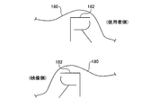
- FIG. 6 is a partially enlarged view showing the identification display 182 displayed on the sign 180 of the eyeglass member 110 in an enlarged manner.
- FIG. 6 shows an identification display 182 viewed from the user wearing the glasses 100 shown in FIG. 1 and an identification display 182 viewed from the side of the video observed by the user through the glasses 100.
- the letter “R” shown as the identification display 182 on the sign 180 has an asymmetric shape in the left-right direction. Therefore, the appearance of the identification display 182 differs between when viewed from the user side and when viewed from the video side. In particular, when viewed from the video side, the identification display 182 is displayed as a mirror image of the alphabet “R”.
- the operator who attaches the eyeglass member 110 can immediately recognize that the direction of the eyeglass member 110 is different.
- the glasses member 110 is attached to the frame 160 in the opposite direction, the user of the glasses 100 can immediately recognize that the direction of the glasses member 110 is different.
- the identification display 182 is formed as a set of open annular patterns that do not include a closed annular pattern. Therefore, even if the identification display 182 is formed by a cut or the like made in the spectacle member 110 itself, a cut-through portion does not occur and a section of the spectacle member 110 does not occur.
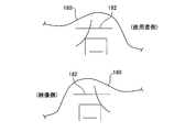
- FIG. 7 is a partially enlarged view illustrating another identification display 182 that can be displayed on the sign section 180 in an enlarged manner.
- FIG. 7 also shows an identification display 182 viewed from the user side wearing the glasses 100 shown in FIG. 1 and an identification display 182 viewed from the video side observed by the user through the glasses 100.
- an identification display 182 having the Chinese character “right” as a motif is displayed. Therefore, when viewed from the user side of the glasses 100, it is intuitively understood that the side on which the sign portion 180 is provided should be positioned on the right side when viewed from the user.
- the character “right” as the identification display 182 has an asymmetric shape in the left-right direction. Therefore, the view is different between when viewed from the user side and when viewed from the video side.
- the identification display 182 is displayed as a mirror image of the alphabet “right”, so it is easy to understand that the left and right of the eyeglass member 110 are different.
- the eyeglass member 110 is attached to the frame 160 in the opposite direction, it is easy to understand.
- the identification display 182 is formed as a set of open annular patterns that do not include a closed annular pattern.
- the identification display 182 is not limited to characters such as “R” or “right”. Further, the identification display 182 may be displayed by a figure, a color, or the like. Furthermore, the identification display 182 formed on the sign section 180 is not limited to a single character or a single symbol. The quality display, product name, manufacturer name, and handling precautions are displayed on the sign section 180 as the identification display 182. You may write.
- the labeling portion 180 may be disposed in either the right eye region 112 or the left eye region 114 of the eyeglass member 110. Further, the marker 180 may be formed so as to protrude outward in the surface direction of the spectacle member 110 along the outer periphery of the spectacle member 110, or a part of the outer periphery of the spectacle member 110 is cut out. May be formed. However, it is preferable to consider the arrangement so that the field of view as the glasses 100 is not narrowed by the sign part 180 and the identification display 182.
- FIG. 8 is a cross-sectional view of the identification display 182 in the sign section 180.
- the cross section shown in FIG. 7 shows a cross section that intersects one of the linear patterns forming the identification display 182.
- the identification display 182 is formed by a notch formed in the thickness direction of the marking portion 180.
- Such an incision can be formed by a half-cut process in which an incision is made shallower than the thickness of the eyeglass member 110. Therefore, by providing a cutting blade having the same shape as the pattern of the identification display 182 and having a different height on the cutting tool used when cutting the glasses member 110, the identification display 182 is provided simultaneously with the cutting processing of the glasses member 110. Can be formed.
- FIG. 9 is a cross-sectional view of another identification display 182 in the sign section 180.
- the cross section shown in FIG. 9 shows a cross section that intersects one of the linear patterns forming the identification display 182.
- the identification display 182 shown in the figure is formed by embossing the marking portion 180.
- the identification display 182 drawn with the thick line can be formed in the label
- the embossing can also be formed by press working using a mold, it can be formed by substantially the same equipment as that for cutting out the glasses member 110.
- the indicator 180 with the identification display 182
- the identification display 182 can be formed by the same equipment and process as the cutout or cutout of the eyeglass member 110 without using other equipment such as painting, printing, sticking, etc., by a method such as half-cutting or embossing.
- identification display 182 may be formed by printing, painting, transfer, or the like. Further, the identification display 182 may be formed by a seal, a sticker, or the like.
- FIG. 10 is a perspective view of glasses 200 according to another embodiment.
- the glasses 200 have the same structure as the glasses 100 shown in FIG. Therefore, the same reference numerals are assigned to elements common to the glasses 200, and redundant description is omitted.
- the glasses 200 include a glasses member 210 and a frame 260 that supports the glasses member 210.
- the glasses 200 have a shape of a part of the fitting projections 264 and 266 provided on the frame 260 and the fitting holes 117 and 119 corresponding to the fitting projections 264 and 266 provided on the glasses member 210. It has a structure different from that of the glasses 100 in terms of shape.
- the shapes of the fitting protrusions 264 and 266 will be described with reference to FIG.
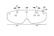
- FIG. 11 is a development view showing the glasses member 210 of the glasses 200 alone.
- the fitting hole 117 arranged in the right eye region 112 has a shape complementary to one fitting protrusion 264 of the frame 260.
- the fitting hole 119 disposed in the left eye region 114 has a shape complementary to the one fitting protrusion 266 of the frame 260.
- the entire width A of the fitting hole 117 formed in the right eye region 112 of the eyeglass member 210 is wider than the width B of the fitting hole 119 arranged in the left eye region 114 of the eyeglass member 210.
- a bridge portion 113 that connects the inside of the fitting hole 117 in the radial direction is provided vertically in the state shown in the drawing.
- the fitting protrusion 264 corresponding to the fitting hole 117 is provided with a groove 265 at a position complementary to the bridge portion 113.
- the fitting hole 117 whose center is blocked by the bridge portion 113 is formed.
- the fitting protrusion 266 cannot be fitted.
- the fitting protrusion 264 having a wide overall width A cannot be fitted into the fitting hole 119 having the narrow width B.
- some of the fitting protrusions 264 and 266 and the fitting holes 117 and 119 form a fitting prevention portion that prevents the fitting between the frame 260 and the glasses member 210. Accordingly, it is possible to prevent the eyeglass member 210 from being attached to the frame 260 in the wrong direction when attempting to attach the eyeglass member 210 in a direction different from a previously assumed direction.
- the glasses member 210 is not attached to the frame 260 in the wrong direction by the fitting prevention portions including the fitting protrusions 264 and 266 and the fitting holes 117 and 119. .
- the marker part 180 of the glasses member 210 may be omitted.
- the shape of the member 210 for glasses can be simplified and it can also make it easy to make the metal mold
- the eyeglass member 210 used for the eyeglasses 200 having the fitting prevention portion is also provided with the mark portion 180 including the identification display 182 that indicates the direction of the eyeglass member 210, the user has been wearing eyeglasses from the beginning. It is easy to recognize the correct orientation of the working member 210. Therefore, the number of times that the fitting of the glasses member 210 to the frame 260 is hindered by the fitting prevention portions including the fitting projections 264 and 266 and the fitting holes 117 and 119 is reduced, and the frame 260 of the glasses member 210 is reduced. Installation can be completed quickly.
- the fitting protrusions 264 and 266 are provided on the eyeglass member 210 side and the fitting holes 117 and 119 are provided on the frame 260, the same function as the glasses 200 shown in the figure can be realized.
- the number, shape, and arrangement of the fitting protrusions 264, 266 and the fitting holes 117, 119 are not limited to the above-described form.
- the marker 180 is provided so as to protrude from the upper side of the right eye region 112.
- the arrangement of the marker 180 is not limited to the upper side of the right eye region 112.
- the marker 180 may be provided at any location along the periphery of the eyeglass member 110 as long as it does not block the view of the user who uses the eyeglasses 100. Therefore, the sign part 180 may be provided on the side part of the member 110 for glasses, or may be provided in the lower part, for example. Further, a marker 180 may be provided in the left eye region 114.
- the marker part 180 in the glasses member 110 are different from the above example, it is preferable to arrange the marker part 180 inside the rectangle R inscribed with the right eye region 112 and the left eye region 114. . Thereby, the use efficiency fall of the material by having provided the label
- the shape of the sign portion 180 is not limited to the shape shown in the figure.
- the shape of the sign part 180 itself may be displayed or suggested by characters, symbols, etc. representing right and left or front and back.
- the shape of the right eye region 112 and the left eye region 114 for example, rounded corners may be made different from each other to form the marker portion 180.
- the marker 180 is not limited to the shape protruding from the eyeglass member 110, and may be a shape cut inward from the periphery of the eyeglass member 110, or may be a depressed portion.
- the structure of the sign part 180 itself is not limited to the above example.
- the sign part 180 may be added to the right eye region 112 and the left eye region 114 once manufactured in a symmetrical shape in a separate process.
- the material of the marking part 180 may be the same material as the right eye region 112 and the left eye region 114, or may be another material.
- the sign part 180 may be attached by an adhesive layer provided on the sign part 180, or may be fixed by adhesion, heat fusion or the like.
Landscapes
- Physics & Mathematics (AREA)
- Health & Medical Sciences (AREA)
- Ophthalmology & Optometry (AREA)
- General Physics & Mathematics (AREA)
- Optics & Photonics (AREA)
- General Health & Medical Sciences (AREA)
- Eyeglasses (AREA)
- Polarising Elements (AREA)
Abstract
メガネ用部材であって、使用者の頭部に装着されるフレームに着脱可能であって、フレームに装着された場合に、使用者の右目および左目の前方に配されるメガネ用部材であって、第1光学軸を有し、使用者の右目前方に位置する右目領域において偏光を変調する右目偏光変調層と、第1光学軸と異なる第2光学軸を有し、使用者の左目前方に位置する左目領域において偏光を変調する左目偏光変調層と、右目偏光変調層および左目偏光変調層の両方に跨がって積層され、右目領域および左目領域で延在方向が等しい吸収軸を有する偏光層と、フレームに対して装着する場合の左右の向きを示す標識部とを備える。
Description
本発明は、メガネ用部材およびメガネに関する。
使用者の右目の前面に位置する右目領域と左目の前面に位置する左目領域とが一体化された立体画像用のメガネがある(例えば、特許文献1参照)。
特許文献1 特開2014-199301号公報
特許文献1 特開2014-199301号公報
しかしながら、上記メガネにおいては右目領域と左目領域が一体化しているので、フレームへの取り付け時に左右が分かりにくいという課題があった。
本発明の一態様においては、使用者の頭部に装着されるフレームに着脱可能であって、フレームに装着された場合に、使用者の右目および左目の前方に配されるメガネ用部材であって、第1光学軸を有し、使用者の右目前方に位置する右目領域において偏光を変調する右目偏光変調層と、第1光学軸と異なる第2光学軸を有し、使用者の左目前方に位置する左目領域において偏光を変調する左目偏光変調層と、右目偏光変調層および左目偏光変調層の両方に跨がって積層され、右目領域および左目領域で延在方向が等しい吸収軸を有する偏光層と、フレームに対して装着する場合の左右の向きを示す標識部とを備えるメガネ用部材が提供される。
本発明の第2の態様においては、上記メガネ用部材と、メガネ用部材を取り付けるフレームとを備えるメガネが提供される。
上記の発明の概要は、本発明の必要な特徴の全てを列挙したものではない。これらの特徴群のサブコンビネーションもまた、発明となりうる。
以下、発明の実施の形態を通じて本発明を説明するが、下記の実施形態は請求の範囲にかかる発明を限定するものではない。また、実施形態の中で説明されている特徴の組み合わせの全てが発明の解決手段に必須であるとは限らない。
図1は、実施形態に係るメガネ100の斜視図である。メガネ100は、メガネ用部材110と、フレーム160とを備える。
メガネ用部材110は、右目領域112、左目領域114および標識部180を有し、入射光の偏光を変調して透過する材料で一体的に形成される。メガネ用部材110における右目領域112および左目領域114は、メガネ100を装着する使用者の右目および左目にそれぞれ対応して配される。
標識部180は、メガネ100の左右について片側に配される。図示の例では、標識部180が右目領域112の上辺から突出して配される。更に、標識部180には、識別表示182が、メガネ100を装着する使用者に向かって表示される。
フレーム160は、嵌合突起部162を有し、メガネ用部材110の一部と嵌まり合うことにより、メガネ用部材110を着脱可能に保持する。メガネ用部材110が装着された状態で使用者の頭部に装着されることにより、メガネ100の使用者の右目前方にメガネ用部材110の右目領域112が配されるとともに、使用者の左目前方にメガネ用部材110の左目領域114が配される。メガネ100の一部としてのフレーム160は、例えば、株式会社モレーンコーポレーションが販売する「ビジエラModel-712(商品名)」を用いることもできる。
図2は、メガネ100の分解斜視図である。メガネ100において、フレーム160は、前方に向かって突出する複数の嵌合突起部162を有する。また、メガネ100において、メガネ用部材110は、嵌合突起部162と相補的な形状および配置で、複数の嵌合穴115を有する。これら、嵌合突起部162および嵌合穴115を相互に嵌め合うことにより、メガネ用部材110を、フレーム160に装着して保持させることができる。
嵌合突起部162は、湾曲したフレーム160の前面に沿って配されるので、全ての嵌合突起部162と嵌合穴115とが嵌まり合った場合、メガネ用部材110も、フレーム160の湾曲に沿って屈曲する。これにより、メガネ用部材110は、フレーム160に対して固定されると共に、高い曲げ剛性を有する状態になる。よって、メガネ100のフレーム160が鼻パッド等の部材を備えていないにもかかわらず、メガネ用部材110自体の剛性により、メガネ用部材110がぶれない状態になる。
なお、メガネ用部材110をフレーム160から強く引き離した場合は、メガネ用部材110およびフレーム160の材料自体の弾性により、嵌合穴115から嵌合突起部162をひとつずつ引き抜くことができる。これにより、使用したメガネ用部材110をフレーム160から取り外して、他のメガネ用部材110と交換できる。このような構造により、メガネ100は、例えば医療用の保護メガネとして使用できる。すなわち、使用毎にメガネ用部材110を交換することにより、メガネ100を清浄な状態で使用し続けることができる。
また、上記の例では、フレーム160に嵌合突起部162を設け、メガネ用部材110に嵌合穴115を設けた。しかしながら、メガネ用部材110側に嵌合突起部162を設け、フレーム160に嵌合穴115を設けても、メガネ100と同じ機能を実現できる。更に、嵌合突起部162および嵌合穴115の数、形状および配置が上記の形態に限定されないことはもちろんである。
図3はメガネ用部材110の模式的な分解斜視図であり、メガネ用部材110の光学的特性を明瞭に示す目的で、外形を四角形にして示している。図3においては、紙面奥側が使用状態における使用者に近い側となる。
メガネ用部材110は、偏光板120、粘着層130、および偏光変調層140を有する。偏光板120は、右目領域112および左目領域114に跨がって一体的に形成され、粘着層130により偏光変調層140に接着される。
上記のメガネ用部材110において、偏光板120は、例えば、偏光層と、当該偏光層を挟む一対の保護層とを有してもよい。偏光層は、例えばポリビニルアルコールにより形成でき、例えば40μmの厚さを有する。保護層は、トリアセチルセルロース(TAC)フィルム、シクロオレフィン系のフィルム等により形成してもよい。
また、上記のメガネ用部材110において、偏光変調層140は、ベース層と、当該ベース上に配された配向膜および液晶層とを有してもよい。ベース層は、例えば、偏光板の保護層と同様の材料を用いて形成できる。また、ベース層は、光学的に等方性を有する他の材料により形成してもよい。ベース層の厚さは、例えば80μmである。ベース層に、更に、ハードコート層、反射防止層等を設けてもよい。
配向膜は、公知の光配向性化合物により、ベース層における右目領域112および左目領域114にそれぞれ形成される。配向膜は、紫外線等の直線偏光を照射された場合に、直線偏光の偏光方向に配向され、更に、積層された液晶層を自身の配向に従って配向させる。配向膜の厚さは、例えば0.1μmである。
液晶層は、配向膜上に配された紫外線硬化性または熱硬化性の液晶ポリマーにより形成できる。液晶層は、配向膜の配向に沿って配向され、円偏光を直線偏光に変調して透過する。液晶層の厚さは、例えば1~2μmである。
上記構成により、メガネ用部材110を備えたメガネ100は、立体画像観賞用に用いることができる。すなわち、立体画像表示装置から右目用画像と左目用画像とが互いに反対周りの円偏光が出力された場合に、右目領域112で右目用画像を透過するとともに左目用画像を遮断する。一方、左目領域114で左目用画像を透過するとともに右目用画像を遮断する。このような光学的構造に鑑みて、メガネ用部材110をフレーム160に装着して使用する場合には、メガネ用部材110の表裏が指定される。
図4は、メガネ100のメガネ用部材110を単独で示す展開図である。図4は、メガネ100を使用する場合に、メガネ100を装着した使用者から見える面、即ち、使用者にとってメガネ100におけるフレーム160の内側から描かれている。
メガネ用部材110は、使用者の使用状態において、使用者の右目の前面に位置する右目領域112と、左目の前面に位置する左目領域114とを有する。ただし、右目領域112および左目領域114は一体的に連続して形成されている。
メガネ用部材110において、標識部180は、右目領域112の上辺に沿って、右目領域112の面方向について上側に突出して設けられる。メガネ用部材110において、標識部180は、メガネ用部材110における標識部180以外の部分、即ち、メガネ用部材110から標識部180を取り除いた部分は、左右対称の外形を有する。
なお、メガネ用部材110において、標識部180は、メガネ用部材110における標識部180以外の部分に外接する、図中に点線で示す矩形Rの内側に位置してもよい。これにより、広いフィルムから切り抜いて複数のメガネ用部材110を製造する場合に、標識部180が無い場合と同じ面積の材料から同じ数のメガネ用部材110を切り抜くことができる。
前述したように、メガネ100を使用する場合には、メガネ用部材110の表裏が指定される。ここで、メガネ用部材110の形状は、上下については全体に非対称な形状を有するので、使用者がメガネ用部材110をフレーム160に装着する場合に上下を間違えることはない。
また、メガネ用部材110は、図示の状態で右側に偏った位置に標識部180を有する。これにより、標識部180を除いた部分が概ね左右対称な形状を有するにもかかわらず、メガネ用部材110は、標識部180により、フレーム160に対して装着する場合の左右の向きを明確に区別できる。よって、使用者がフレーム160にメガネ用部材110を取り付ける場合に、標識部180を視認することにより、メガネ用部材110の左右の別を容易に識別できる。
更に、図示の例では、「右」を意味するアルファベットの「R」をモチーフとした識別表示182が、メガネ100を装着する使用者の側に面して、標識部180に表示されている。よって、メガネ100を使用者側から見た場合に、標識部180が設けられている側が、使用者から見て右側に位置すべきことが、取り扱い説明書等を読むことなく、直観的に理解される。これにより、標識部180が、メガネ用部材110の右側を示すのか、左側を示すのかを認識でき、メガネ用部材110の左右の別を確実に識別できる。なお、標識部180における識別表示182の表示は省いてもよい。その場合は、標識部180自体の有無により、メガネ用部材110の左右が区別される。
図5は、フレーム160にメガネ用部材110を取り付ける過程を示す図である。図1に示したように、フレーム160に取り付けられたメガネ用部材110は、フレーム160に沿って湾曲している。しかしながら、図5に示すように、フレーム160に取り付ける前のメガネ用部材110は湾曲していない。平坦なメガネ用部材110は、全ての嵌合穴115を嵌合突起部162に嵌合させる過程で湾曲する。
このため、フレーム160の嵌合突起部162とメガネ用部材110の嵌合穴115とがそれぞれ左右対称に形成されている場合は、メガネ用部材110の左右が入れ替わっても、フレーム160に装着することができる。メガネ用部材110の左右が入れ替わっている場合、メガネ100を装着した使用者から見ると、メガネ用部材110の表裏が反対になり、立体映像を観察する場合に所期の光学特性が発揮されなくなる。
しかしながら、メガネ用部材110は、使用者から見て右側に配された標識部180を有する。また、標識部180には左右の別を示す識別表示182が表示される。よって、メガネ用部材110をフレーム160に取り付ける場合に、使用者から見た標識部180が右側に位置することが認識されていれば、メガネ用部材110の装着の向きを誤ることが確実に防止される。
また、標識部180に設けた識別表示182は、メガネ100に組み立てて使用者に装着された状態において、使用者以外からも視認できる。よって、何らかの理由でメガネ用部材110のフレーム160に対する装着方向が誤っていた場合に、メガネ100の使用方法を知らない他者が見て、メガネ用部材110の装着方向が誤っていることを指摘できる。
図6は、メガネ用部材110の標識部180に表示された識別表示182を拡大して示す部分拡大図である。図6には、図1に示したメガネ100を装着した使用者側から見た識別表示182と、メガネ100を通じて使用者が観察する映像の側から見た識別表示182とを併せて示す。
標識部180に識別表示182として示される文字「R」は、左右方向について非対称な形状を有する。よって、使用者側から見た場合と、映像側から見た場合とで、識別表示182の見え方が異なる。特に、映像側から見た場合に、識別表示182は、アルファベット「R」の鏡像として表示される。
よって、左右が反対になる向きでメガネ用部材110をフレーム160に取り付けようとした場合、メガネ用部材110を取り付ける作業者は、メガネ用部材110の向きが異なっていることを即座に認識できる。また、メガネ用部材110が、左右が反対になる向きでフレーム160に取り付けられている場合、メガネ100の使用者は、メガネ用部材110の向きが異なっていることを即座に認識できる。
なお、識別表示182として表示されたアルファベット「R」においては、文字の上半分に形成される環状のパターンの一部が切断されている。これにより、識別表示182は、閉じた環状のパターンを含まない開環状パターンの集合として形成される。よって、識別表示182を、メガネ用部材110自体に入れた切り込み等により形成した場合であっても、くり貫部が発生せず、メガネ用部材110の切片が生じない。
図7は、標識部180に表示できる他の識別表示182を拡大して例示する部分拡大図である。図7には、図1に示したメガネ100を装着した使用者側から見た識別表示182と、メガネ100を通じて使用者が観察する映像の側から見た識別表示182とを併せて示す。
図7に示す標識部180においては、漢字の「右」をモチーフとした識別表示182が表示される。よって、メガネ100の使用者側から見た場合に、標識部180が設けられている側が、使用者から見て右側に位置すべきことが直観的に理解される。
識別表示182としての文字「右」は、左右方向について非対称な形状を有する。よって、使用者側から見た場合と、映像側から見た場合とで見え方が異なる。特に、映像側から見た場合に、識別表示182は、アルファベット「右」の鏡像として表示されるので、メガネ用部材110の左右が異なることが判りやすい。左右が反対になる向きでメガネ用部材110をフレーム160に取り付けようとした場合も同様に判りやすい。
更に、識別表示182として表示された文字「右」においては、文字のした半分に形成された環状のパターンの一部が切断されている。これにより、識別表示182は、閉じた環状のパターンを含まない開環状パターンの集合として形成される。
なお、識別表示182が「R」または「右」等の文字に限られないことはもちろんである。また、識別表示182は、図形、色彩等により表示されてもよい。更に、標識部180に形成する識別表示182が一文字または単一の記号に限らないことはもちろんであり、品質表示、商品名、製造者名、取り扱い上の注意を識別表示182として標識部180に書き込んでもよい。
このように、標識部180は、メガネ用部材110の右目領域112および左目領域114のいずれか一方に配されてもよい。また、標識部180は、メガネ用部材110の外周に沿って、メガネ用部材110の面方向について外側に向かって突出して形成されてもよいし、メガネ用部材110の外周の一部を切り欠くことにより形成してもよい。ただし、標識部180および識別表示182により、メガネ100としての視野を狭めないように配置を配慮することが好ましい。
図8は、標識部180における識別表示182の断面図である。図7に示す断面は、識別表示182を形成する線状のパターンのひとつと交差する断面を示す。
図示のように、識別表示182は、標識部180の厚さ方向に形成した切り込みにより形成される。このような切り込みは、メガネ用部材110の厚さよりも浅く切り込みを入れるハーフカット加工により形成できる。よって、メガネ用部材110を切り出す場合に使用する刃物に、識別表示182のパターンと同じ形状を有し、高さが異なる切り刃を設けることにより、メガネ用部材110の切り出し加工と同時に識別表示182を形成できる。
図9は、標識部180における他の識別表示182の断面図である。図9に示す断面は、識別表示182を形成する線状のパターンのひとつと交差する断面を示す。
図示の識別表示182は、標識部180に対するエンボス加工により形成される。これにより、切り粉、粉塵等を発生することなく、太い線で描かれた識別表示182を標識部180に形成できる。また、エンボス加工も、金型を用いたプレス加工により形成できるので、メガネ用部材110の切り抜きと略同じ設備により形成できる。
このように、標識部180に、更に、識別表示182を設けることにより、メガネ用部材110の左右の向きをより確実に認識させることができる。また、ハーフカット、エンボス等の方法により、塗装、印刷、貼付等の他の設備を用いることなく、メガネ用部材110の切り抜きまたは切り出しと同じ設備および工程で識別表示182を形成できる。
なお、ハーフカット加工およびエンボス加工により識別表示182を形成する例について説明したが、識別表示182の形成は、上記の方法に限定されない。例えば、識別表示182は、印刷、塗装、転写等により形成してもよい。また、シール、ステッカー等により識別表示182を形成してもよい。
図10は、他の実施形態に係るメガネ200の斜視図である。メガネ200は、次に説明する部分を除くと、図1等に示したメガネ100と同じ構造を有する。よって、メガネ200と共通の要素には同じ参照番号を付して重複する説明を省く。メガネ200は、メガネ用部材210と、メガネ用部材210を支持するフレーム260とを有する。
メガネ200は、フレーム260に設けられた一部の嵌合突起部264、266の形状と、メガネ用部材210に設けられて、嵌合突起部264、266に対応する嵌合穴117、119の形状とにおいて、メガネ100と異なる構造を有する。嵌合突起部264、266の形状については、図10を参照して説明する。
図11は、メガネ200のメガネ用部材210を単独で示す展開図である。メガネ用部材210において、右目領域112に配された嵌合穴117は、フレーム260のひとつの嵌合突起部264と相補的な形状を有する。また、メガネ用部材210において、左目領域114に配された嵌合穴119は、フレーム260のひとつの嵌合突起部266と相補的な形状を有する。
ここで、メガネ用部材210の右目領域112に形成された嵌合穴117の全体の幅Aは、メガネ用部材210の左目領域114に配された嵌合穴119の幅Bよりも広い。また、嵌合穴117の幅方向中央には、嵌合穴117の内側を径方向に結ぶブリッジ部113が図に示した状態で縦に設けられる。なお、図10に示すように、嵌合穴117に対応する嵌合突起部264には、ブリッジ部113と相補的な位置に、溝265が設けられている。
このため、メガネ200において、メガネ用部材210を、左右方向について、予め想定された向きと異なる向きでフレーム260に取り付けようとした場合、中央がブリッジ部113により塞がれた嵌合穴117に、嵌合突起部266を嵌めることはできない。また、狭い幅Bを有する嵌合穴119に、全体の幅Aが広い嵌合突起部264を嵌めることはできない。
このように、メガネ200においては、一部の嵌合突起部264、266および嵌合穴117、119が、フレーム260とメガネ用部材210との嵌合を阻止する嵌合阻止部を形成する。これにより、予め想定された向きと異なる向きでメガネ用部材210を装着しようとした場合に間違った向きでメガネ用部材210をフレーム260に取り付けることを未然に防止できる。
上記のように、メガネ200においては、嵌合突起部264、266および嵌合穴117、119を含む嵌合阻止部により、メガネ用部材210が誤った向きでフレーム260に装着されることはない。このような嵌合阻止部をメガネ200に形成した場合は、メガネ用部材210の標識部180を省略してもよい。これにより、メガネ用部材210の形状を簡潔にして、切り出し加工の金型を造りやすくすることもできる。
一方、嵌合阻止部を有するメガネ200に使用するメガネ用部材210にも、メガネ用部材210の向きを示す、識別表示182を含む標識部180を設けた場合は、使用者が、当初よりメガネ用部材210の正しい向きを認識しやすい。よって、メガネ用部材210のフレーム260への装着が、嵌合突起部264、266および嵌合穴117、119を含む嵌合阻止部により妨げられる回数を軽減して、メガネ用部材210のフレーム260に対する取り付けを迅速に完了できる。
なお、この実施形態においても、メガネ用部材210側に嵌合突起部264、266を設け、フレーム260に嵌合穴117、119を設けても、図示のメガネ200と同じ機能を実現できる。また、嵌合突起部264、266および嵌合穴117、119の数、形状および配置が上記の形態に限定されないことはもちろんである。
ここまでに例示したメガネ用部材110、210では、標識部180を、右目領域112の上辺から突出するように設けた。しかしながら、標識部180の配置は、右目領域112の上側に限られるわけではない。メガネ100を使用する使用者の視界を遮らない位置であれば、標識部180は、メガネ用部材110の周縁に沿っていかなる場所に設けてもよい。よって、標識部180は、例えば、メガネ用部材110の側部に設けてもよいし、下部に設けてもよい。また、左目領域114に標識部180を設けてもよい。
なお、メガネ用部材110において標識部180の配置および形状が上記の例と異なる場合であっても、右目領域112および左目領域114が内接する矩形Rの内側に標識部180を配することが好ましい。これにより、標識部180を設けたことによる材料の利用効率低下を防止できる。
また、標識部180の形状も図示の形状に限らない。例えば、標識部180の形状自体を、左右または表裏を表す文字、記号等を表示または示唆するものとしてもよい。また、右目領域112および左目領域114の形状、例えば角の丸みを相互に異ならせて標識部180を形成してもよい。更に、標識部180は、メガネ用部材110から突出した形状に限られず、メガネ用部材110の周縁から内側に切り込んだ形状であってよいし、陥没部等であってもよい。
更に、標識部180自体の構造も上記の例に限定されず、例えば、いったん左右対称な形状で製造した右目領域112および左目領域114に対して、別工程で標識部180を付加してもよい。標識部180の材料も、右目領域112および左目領域114と同じ材料でもよいし、他の材料であってもよい。また、標識部180の取り付け方法としても、標識部180に設けた粘着層により貼り付けてもよいし、接着、熱融着等により固定してもよい。
以上、本発明を実施の形態を用いて説明したが、本発明の技術的範囲は上記実施の形態に記載の範囲には限定されない。上記実施の形態に、多様な変更または改良を加えることが可能であることが当業者に明らかである。その様な変更または改良を加えた形態も本発明の技術的範囲に含まれ得ることが、請求の範囲の記載から明らかである。
請求の範囲、明細書、および図面中において示した装置、システム、プログラム、および方法における動作、手順、ステップ、および段階等の各処理の実行順序は、特段「より前に」、「先立って」等と明示しておらず、また、前の処理の出力を後の処理で用いるのでない限り、任意の順序で実現しうることに留意すべきである。請求の範囲、明細書、および図面中の動作フローに関して、便宜上「まず、」、「次に、」等を用いて説明したとしても、この順で実施することが必須であることを意味するものではない。
100、200 メガネ、110、210 メガネ用部材、113 ブリッジ部、115、117、119 嵌合穴、112 右目領域、114 左目領域、120 偏光板、130 粘着層、140 偏光変調層、160、260 フレーム、162、264、266 嵌合突起部、180 標識部、182 識別表示、265 溝
Claims (8)
- 使用者の頭部に装着されるフレームに着脱可能であって、前記フレームに装着された場合に、前記使用者の右目および左目の前方に配されるメガネ用部材であって、
第1光学軸を有し、使用者の右目前方に位置する右目領域において偏光を変調する右目偏光変調層と、
前記第1光学軸と異なる第2光学軸を有し、前記使用者の左目前方に位置する左目領域において偏光を変調する左目偏光変調層と、
前記右目偏光変調層および前記左目偏光変調層の両方に跨がって積層され、前記右目領域および前記左目領域で延在方向が等しい吸収軸を有する偏光層と、
前記フレームに対して装着する場合の左右の向きを示す標識部と
を備えるメガネ用部材。 - 前記標識部は、前記右目領域および前記左目領域のいずれか一方に配される請求項1に記載のメガネ用部材。
- 前記標識部には、左右方向について非対称な形状を有する記号が付される請求項1または2に記載のメガネ用部材。
- 前記記号は、前記メガネ用部材に対するハーフカットにより形成される請求項3に記載のメガネ用部材。
- 前記記号は、前記メガネ用部材の面方向について開環状パターンの集合により形成される請求項4に記載のメガネ用部材。
- 前記標識部は、前記メガネ用部材の面方向について外側に向かって突出して形成される請求項1から5のいずれか一項に記載のメガネ用部材。
- 請求項1から6のいずれか一項に記載のメガネ用部材と、前記メガネ用部材を取り付けるフレームとを備えるメガネ。
- 前記メガネ用部材の一部に対して嵌合して前記フレームおよび前記メガネ用部材を相互に位置決めする嵌合部と、
前記フレームの前記メガネ用部材に対する向きが予め想定した向きと異なる場合に、前記嵌合部の嵌合を阻止する嵌合阻止部と
を有する請求項7に記載のメガネ。
Priority Applications (7)
| Application Number | Priority Date | Filing Date | Title |
|---|---|---|---|
| JP2016509200A JPWO2016157331A1 (ja) | 2015-03-27 | 2015-03-27 | メガネ用部材およびメガネ |
| EP15887484.2A EP3273291A4 (en) | 2015-03-27 | 2015-03-27 | Member for eyeglasses and eyeglasses |
| CN201580077685.2A CN107407822A (zh) | 2015-03-27 | 2015-03-27 | 眼镜用部件及眼镜 |
| PCT/JP2015/059761 WO2016157331A1 (ja) | 2015-03-27 | 2015-03-27 | メガネ用部材およびメガネ |
| TW106210792U TWM551704U (zh) | 2015-03-27 | 2016-03-10 | 眼鏡用構件及眼鏡 |
| TW105107347A TW201702691A (zh) | 2015-03-27 | 2016-03-10 | 眼鏡用構件及眼鏡 |
| US15/716,545 US20180017804A1 (en) | 2015-03-27 | 2017-09-27 | Eyeglass member and pair of eyeglasses |
Applications Claiming Priority (1)
| Application Number | Priority Date | Filing Date | Title |
|---|---|---|---|
| PCT/JP2015/059761 WO2016157331A1 (ja) | 2015-03-27 | 2015-03-27 | メガネ用部材およびメガネ |
Related Child Applications (1)
| Application Number | Title | Priority Date | Filing Date |
|---|---|---|---|
| US15/716,545 Continuation US20180017804A1 (en) | 2015-03-27 | 2017-09-27 | Eyeglass member and pair of eyeglasses |
Publications (1)
| Publication Number | Publication Date |
|---|---|
| WO2016157331A1 true WO2016157331A1 (ja) | 2016-10-06 |
Family
ID=57004870
Family Applications (1)
| Application Number | Title | Priority Date | Filing Date |
|---|---|---|---|
| PCT/JP2015/059761 Ceased WO2016157331A1 (ja) | 2015-03-27 | 2015-03-27 | メガネ用部材およびメガネ |
Country Status (6)
| Country | Link |
|---|---|
| US (1) | US20180017804A1 (ja) |
| EP (1) | EP3273291A4 (ja) |
| JP (1) | JPWO2016157331A1 (ja) |
| CN (1) | CN107407822A (ja) |
| TW (2) | TWM551704U (ja) |
| WO (1) | WO2016157331A1 (ja) |
Citations (8)
| Publication number | Priority date | Publication date | Assignee | Title |
|---|---|---|---|---|
| JPS6219620U (ja) * | 1985-07-22 | 1987-02-05 | ||
| JPH05504849A (ja) * | 1990-12-11 | 1993-07-22 | グレンデルマイアー、アレキサンダー | 眼鏡 |
| JP2011138108A (ja) * | 2009-12-01 | 2011-07-14 | Minoru Inaba | 立体映像観賞用メガネ |
| JP2011197629A (ja) * | 2010-02-23 | 2011-10-06 | Yamamoto Kogaku Co Ltd | 円偏光板および円偏光レンズ、および円偏光眼鏡 |
| JP2012088369A (ja) * | 2010-10-15 | 2012-05-10 | Toshiba Mobile Display Co Ltd | 眼鏡用液晶シャッタセット及びその製造方法 |
| JP2013501443A (ja) * | 2009-08-06 | 2013-01-10 | ソニー ヨーロッパ リミテッド | 3d画像表示方法、3d画像表示装置、シャッターメガネ、プログラムおよびコンピュータ可読記録媒体 |
| JP2013016961A (ja) * | 2011-07-01 | 2013-01-24 | Sanyo Electric Co Ltd | 3dメガネ、および3dメガネセット |
| JP2014199301A (ja) * | 2013-03-29 | 2014-10-23 | 株式会社有沢製作所 | メガネ用部材、メガネおよびメガネ用部材の製造方法 |
Family Cites Families (7)
| Publication number | Priority date | Publication date | Assignee | Title |
|---|---|---|---|---|
| US5062701A (en) * | 1988-06-07 | 1991-11-05 | Wesley-Jessen Corporation | Asymmetric contact lens |
| US7188947B1 (en) * | 2006-03-22 | 2007-03-13 | Chin-Jen Chen | Lens combined with a soft eyeglasses rim |
| US7524053B2 (en) * | 2006-05-12 | 2009-04-28 | Real D | 3-D eyewear |
| WO2012078197A1 (en) * | 2010-01-22 | 2012-06-14 | Oakley, Inc. | Eyewear with three-dimensional viewing capability |
| JP2011257454A (ja) * | 2010-06-04 | 2011-12-22 | Sony Corp | シャッター眼鏡 |
| SG187802A1 (en) * | 2010-08-13 | 2013-03-28 | Oakley Inc | Eyewear with lens retention mechanism |
| CN105204105A (zh) * | 2014-06-12 | 2015-12-30 | 株式会社有泽制作所 | 眼镜用部件、眼镜及眼镜用部件的制造方法 |
-
2015
- 2015-03-27 EP EP15887484.2A patent/EP3273291A4/en not_active Withdrawn
- 2015-03-27 WO PCT/JP2015/059761 patent/WO2016157331A1/ja not_active Ceased
- 2015-03-27 JP JP2016509200A patent/JPWO2016157331A1/ja active Pending
- 2015-03-27 CN CN201580077685.2A patent/CN107407822A/zh active Pending
-
2016
- 2016-03-10 TW TW106210792U patent/TWM551704U/zh unknown
- 2016-03-10 TW TW105107347A patent/TW201702691A/zh unknown
-
2017
- 2017-09-27 US US15/716,545 patent/US20180017804A1/en not_active Abandoned
Patent Citations (8)
| Publication number | Priority date | Publication date | Assignee | Title |
|---|---|---|---|---|
| JPS6219620U (ja) * | 1985-07-22 | 1987-02-05 | ||
| JPH05504849A (ja) * | 1990-12-11 | 1993-07-22 | グレンデルマイアー、アレキサンダー | 眼鏡 |
| JP2013501443A (ja) * | 2009-08-06 | 2013-01-10 | ソニー ヨーロッパ リミテッド | 3d画像表示方法、3d画像表示装置、シャッターメガネ、プログラムおよびコンピュータ可読記録媒体 |
| JP2011138108A (ja) * | 2009-12-01 | 2011-07-14 | Minoru Inaba | 立体映像観賞用メガネ |
| JP2011197629A (ja) * | 2010-02-23 | 2011-10-06 | Yamamoto Kogaku Co Ltd | 円偏光板および円偏光レンズ、および円偏光眼鏡 |
| JP2012088369A (ja) * | 2010-10-15 | 2012-05-10 | Toshiba Mobile Display Co Ltd | 眼鏡用液晶シャッタセット及びその製造方法 |
| JP2013016961A (ja) * | 2011-07-01 | 2013-01-24 | Sanyo Electric Co Ltd | 3dメガネ、および3dメガネセット |
| JP2014199301A (ja) * | 2013-03-29 | 2014-10-23 | 株式会社有沢製作所 | メガネ用部材、メガネおよびメガネ用部材の製造方法 |
Non-Patent Citations (1)
| Title |
|---|
| See also references of EP3273291A4 * |
Also Published As
| Publication number | Publication date |
|---|---|
| US20180017804A1 (en) | 2018-01-18 |
| TWM551704U (zh) | 2017-11-11 |
| JPWO2016157331A1 (ja) | 2018-01-18 |
| CN107407822A (zh) | 2017-11-28 |
| EP3273291A4 (en) | 2018-10-24 |
| TW201702691A (zh) | 2017-01-16 |
| EP3273291A1 (en) | 2018-01-24 |
Similar Documents
| Publication | Publication Date | Title |
|---|---|---|
| JP5272122B2 (ja) | 光学素子アレイシート、表示装置、及びこれらの製造方法 | |
| JP6364936B2 (ja) | 画像表示装置 | |
| CN103293755B (zh) | 立体显示装置 | |
| JPWO2008142846A1 (ja) | 立体画像表示装置 | |
| US10133071B2 (en) | Replaceable optical element for near eye display | |
| WO2015170716A1 (ja) | 眼鏡用保護具 | |
| JP2012032445A (ja) | 積層体の製造方法、位相差板の製造方法および位相差板 | |
| KR20160100004A (ko) | 표시 장치 | |
| CN110088668A (zh) | 镜片及眼睛佩戴物 | |
| CN111458875A (zh) | 光学成像装置 | |
| US10310165B2 (en) | Image display apparatus | |
| JP2013083784A (ja) | 偏光フィルムの貼付方法 | |
| BR112014022446B1 (pt) | Sistema para a visualização estereoscópica de informação de imagem, óculos para a visualização de imagens tridimensionais e processo para visualização de informação de imagem estereoscópica | |
| WO2016157331A1 (ja) | メガネ用部材およびメガネ | |
| JP6441103B2 (ja) | 画像表示装置 | |
| JP2023057103A (ja) | ヘッドマウントディスプレイ | |
| JP2014199301A (ja) | メガネ用部材、メガネおよびメガネ用部材の製造方法 | |
| JP2003167216A (ja) | 3d映像表示装置及び3d映像表示装置用の偏光メガネ | |
| JP4906777B2 (ja) | 装用確認用シート | |
| KR101106774B1 (ko) | 입체 디스플레이 장치 및 그 제조 방법 | |
| WO2026096778A1 (en) | Ophthalmic waveguide blanks for display systems | |
| JP4300886B2 (ja) | 立体視用ビュアー | |
| JP6488870B2 (ja) | 光学レンズの製造方法 | |
| KR20130054704A (ko) | 시역 분리용 기판, 이를 포함한 입체 영상 디스플레이 장치 및 시역 분리용 기판의 제조방법 | |
| US20150370083A1 (en) | Wearable stereoscopic viewer |
Legal Events
| Date | Code | Title | Description |
|---|---|---|---|
| ENP | Entry into the national phase |
Ref document number: 2016509200 Country of ref document: JP Kind code of ref document: A |
|
| 121 | Ep: the epo has been informed by wipo that ep was designated in this application |
Ref document number: 15887484 Country of ref document: EP Kind code of ref document: A1 |
|
| NENP | Non-entry into the national phase |
Ref country code: DE |
|
| REEP | Request for entry into the european phase |
Ref document number: 2015887484 Country of ref document: EP |