WO2016157331A1 - Élément pour lunettes et lunettes - Google Patents
Élément pour lunettes et lunettes Download PDFInfo
- Publication number
- WO2016157331A1 WO2016157331A1 PCT/JP2015/059761 JP2015059761W WO2016157331A1 WO 2016157331 A1 WO2016157331 A1 WO 2016157331A1 JP 2015059761 W JP2015059761 W JP 2015059761W WO 2016157331 A1 WO2016157331 A1 WO 2016157331A1
- Authority
- WO
- WIPO (PCT)
- Prior art keywords
- glasses
- frame
- eye
- user
- eyeglass
- Prior art date
- Legal status (The legal status is an assumption and is not a legal conclusion. Google has not performed a legal analysis and makes no representation as to the accuracy of the status listed.)
- Ceased
Links
Images




Classifications
-
- G—PHYSICS
- G02—OPTICS
- G02B—OPTICAL ELEMENTS, SYSTEMS OR APPARATUS
- G02B30/00—Optical systems or apparatus for producing three-dimensional [3D] effects, e.g. stereoscopic images
- G02B30/20—Optical systems or apparatus for producing three-dimensional [3D] effects, e.g. stereoscopic images by providing first and second parallax images to an observer's left and right eyes
- G02B30/22—Optical systems or apparatus for producing three-dimensional [3D] effects, e.g. stereoscopic images by providing first and second parallax images to an observer's left and right eyes of the stereoscopic type
- G02B30/25—Optical systems or apparatus for producing three-dimensional [3D] effects, e.g. stereoscopic images by providing first and second parallax images to an observer's left and right eyes of the stereoscopic type using polarisation techniques
-
- G—PHYSICS
- G02—OPTICS
- G02B—OPTICAL ELEMENTS, SYSTEMS OR APPARATUS
- G02B5/00—Optical elements other than lenses
- G02B5/30—Polarising elements
-
- G—PHYSICS
- G02—OPTICS
- G02C—SPECTACLES; SUNGLASSES OR GOGGLES INSOFAR AS THEY HAVE THE SAME FEATURES AS SPECTACLES; CONTACT LENSES
- G02C7/00—Optical parts
- G02C7/02—Lenses; Lens systems ; Methods of designing lenses
-
- G—PHYSICS
- G02—OPTICS
- G02C—SPECTACLES; SUNGLASSES OR GOGGLES INSOFAR AS THEY HAVE THE SAME FEATURES AS SPECTACLES; CONTACT LENSES
- G02C7/00—Optical parts
- G02C7/02—Lenses; Lens systems ; Methods of designing lenses
- G02C7/021—Lenses; Lens systems ; Methods of designing lenses with pattern for identification or with cosmetic or therapeutic effects
-
- G—PHYSICS
- G02—OPTICS
- G02C—SPECTACLES; SUNGLASSES OR GOGGLES INSOFAR AS THEY HAVE THE SAME FEATURES AS SPECTACLES; CONTACT LENSES
- G02C7/00—Optical parts
- G02C7/12—Polarisers
-
- G—PHYSICS
- G02—OPTICS
- G02B—OPTICAL ELEMENTS, SYSTEMS OR APPARATUS
- G02B7/00—Mountings, adjusting means, or light-tight connections, for optical elements
- G02B7/006—Filter holders
-
- G—PHYSICS
- G02—OPTICS
- G02C—SPECTACLES; SUNGLASSES OR GOGGLES INSOFAR AS THEY HAVE THE SAME FEATURES AS SPECTACLES; CONTACT LENSES
- G02C2200/00—Generic mechanical aspects applicable to one or more of the groups G02C1/00 - G02C5/00 and G02C9/00 - G02C13/00 and their subgroups
- G02C2200/32—Oblong hole
Definitions
- the present invention relates to a member for glasses and glasses.
- Patent Document 1 JP 2014-199301 A
- the eyeglass member is detachable from a frame attached to the user's head and is disposed in front of the user's right eye and left eye when attached to the frame.
- a right-eye polarization modulation layer that modulates polarization in a right-eye region located in front of the user's right eye, and a second optical axis that is different from the first optical axis.
- the left-eye polarization modulation layer that modulates the polarization in the left-eye region located in front of the eye, and the absorption axis that is stacked across both the right-eye polarization modulation layer and the left-eye polarization modulation layer and has the same extending direction in the right-eye region and the left-eye region
- a member for eyeglasses comprising a polarizing layer having a mark and a sign portion indicating a right and left direction when attached to a frame.
- glasses comprising the above-described glasses member and a frame to which the glasses member is attached.
- FIG. 1 is a perspective view of glasses 100.
- FIG. 2 is an exploded perspective view of glasses 100.
- FIG. It is a disassembled perspective view which shows the layer structure of the member 110 for glasses.
- It is a front view of member 110 for glasses. It is a figure explaining the assembly of glasses 100.
- FIG. It is the elements on larger scale of the identification display 182.
- It is the elements on larger scale of the identification display 182.
- 5 is a partial cross-sectional view of identification display 182.
- FIG. It is an identification display 182 partial sectional view.
- 2 is a perspective view of glasses 200.
- FIG. It is a front view of the member 210 for glasses.
- FIG. 1 is a perspective view of glasses 100 according to the embodiment.
- the glasses 100 include a glasses member 110 and a frame 160.
- the eyeglass member 110 has a right eye region 112, a left eye region 114, and a marker 180, and is integrally formed of a material that modulates and transmits the polarization of incident light.
- the right eye region 112 and the left eye region 114 in the eyeglass member 110 are arranged corresponding to the right eye and the left eye of the user wearing the eyeglasses 100, respectively.
- the sign part 180 is arranged on one side with respect to the left and right sides of the glasses 100.
- the marker 180 is disposed so as to protrude from the upper side of the right eye region 112.
- an identification display 182 is displayed on the sign unit 180 toward the user wearing the glasses 100.
- the frame 160 has a fitting projection 162 and fits with a part of the glasses member 110, thereby holding the glasses member 110 detachably.
- the right eye region 112 of the eyeglass member 110 is arranged in front of the right eye of the user of the eyeglass 100 and the user's left side A left eye region 114 of the eyeglass member 110 is disposed in front of the eyes.
- the frame 160 as a part of the glasses 100, for example, “Bijiela Model-712 (trade name)” sold by Moraine Corporation may be used.
- FIG. 2 is an exploded perspective view of the glasses 100.
- the frame 160 has a plurality of fitting protrusions 162 protruding forward.
- the glasses member 110 has a plurality of fitting holes 115 in a shape and arrangement complementary to the fitting protrusion 162. By fitting the fitting protrusion 162 and the fitting hole 115 to each other, the member 110 for glasses can be attached to the frame 160 and held.
- the eyeglass member 110 Since the fitting protrusions 162 are arranged along the front surface of the curved frame 160, when all the fitting protrusions 162 and the fitting holes 115 are fitted, the eyeglass member 110 is also attached to the frame 160. Bend along the curve. As a result, the glasses member 110 is fixed to the frame 160 and has a high bending rigidity. Therefore, even though the frame 160 of the glasses 100 does not include a member such as a nose pad, the glasses member 110 does not shake due to the rigidity of the glasses member 110 itself.
- the glasses member 110 When the glasses member 110 is strongly pulled away from the frame 160, the fitting protrusions 162 can be pulled out one by one from the fitting holes 115 due to the elasticity of the materials of the glasses member 110 and the frame 160 themselves. Thereby, the used member 110 for glasses can be removed from the flame
- the glasses 100 can be used as, for example, medical protective glasses. That is, the glasses 100 can be used in a clean state by exchanging the glasses member 110 for each use.
- the fitting protrusion 162 is provided on the frame 160 and the fitting hole 115 is provided on the eyeglass member 110.
- the same function as the glasses 100 can be realized.
- the number, shape, and arrangement of the fitting protrusions 162 and the fitting holes 115 are not limited to the above-described form.
- FIG. 3 is a schematic exploded perspective view of the eyeglass member 110, in which the outer shape is shown as a square for the purpose of clearly showing the optical characteristics of the eyeglass member 110.
- the back side of the paper is the side closer to the user in the use state.
- the eyeglass member 110 includes a polarizing plate 120, an adhesive layer 130, and a polarization modulation layer 140.
- the polarizing plate 120 is integrally formed across the right eye region 112 and the left eye region 114 and is adhered to the polarization modulation layer 140 by the adhesive layer 130.
- the polarizing plate 120 may include, for example, a polarizing layer and a pair of protective layers sandwiching the polarizing layer.
- the polarizing layer can be formed of, for example, polyvinyl alcohol and has a thickness of, for example, 40 ⁇ m.
- the protective layer may be formed of a triacetyl cellulose (TAC) film, a cycloolefin film, or the like.
- the polarization modulation layer 140 may include a base layer and an alignment film and a liquid crystal layer disposed on the base.
- the base layer can be formed using, for example, the same material as the protective layer of the polarizing plate. Further, the base layer may be formed of another material having optical isotropy. The thickness of the base layer is, for example, 80 ⁇ m.
- a hard coat layer, an antireflection layer, and the like may be further provided on the base layer.
- the alignment film is formed in the right eye region 112 and the left eye region 114 in the base layer by a known photo-alignment compound.
- the alignment film is aligned in the polarization direction of the linearly polarized light when irradiated with linearly polarized light such as ultraviolet rays, and further aligns the laminated liquid crystal layer according to its own alignment.
- the thickness of the alignment film is, for example, 0.1 ⁇ m.
- the liquid crystal layer can be formed of an ultraviolet curable or thermosetting liquid crystal polymer disposed on the alignment film.
- the liquid crystal layer is oriented along the orientation of the orientation film, and modulates and transmits circularly polarized light into linearly polarized light.
- the thickness of the liquid crystal layer is, for example, 1 to 2 ⁇ m.
- the glasses 100 provided with the glasses member 110 can be used for stereoscopic image viewing. That is, when the right-eye image and the left-eye image output circularly polarized light opposite to each other from the stereoscopic image display device, the right-eye image is transmitted through the right-eye region 112 and the left-eye image is blocked. On the other hand, the left eye image is transmitted through the left eye region 114 and the right eye image is blocked.
- the spectacle member 110 is mounted on the frame 160 and used, the front and back of the spectacle member 110 are designated.
- FIG. 4 is a development view showing the glasses member 110 of the glasses 100 independently.
- FIG. 4 is drawn from the inside of the frame 160 of the glasses 100 for the user, that is, the surface that is visible to the user wearing the glasses 100 when the glasses 100 are used.
- the member 110 for glasses has the right eye area
- the right eye region 112 and the left eye region 114 are integrally formed continuously.
- the marker 180 is provided so as to protrude upward in the surface direction of the right eye region 112 along the upper side of the right eye region 112.
- the sign portion 180 has a symmetrical outer shape in a portion other than the sign portion 180 in the spectacle member 110, that is, a portion obtained by removing the sign portion 180 from the spectacle member 110.
- the sign portion 180 may be located inside a rectangle R that is circumscribed by a portion other than the sign portion 180 in the eyeglass member 110 and indicated by a dotted line in the drawing.
- the front and back of the glasses member 110 are designated.
- the shape of the eyeglass member 110 is asymmetrical in the upper and lower sides, and therefore, when the user wears the eyeglass member 110 on the frame 160, there is no mistake in the upper and lower sides.
- the member 110 for glasses has the label
- the glasses member 110 clearly distinguishes the left and right orientations when the eyeglass member 110 is attached to the frame 160, even though the portion excluding the sign portion 180 has a substantially bilaterally symmetric shape. it can. Therefore, when the user attaches the eyeglass member 110 to the frame 160, the right and left distinction of the eyeglass member 110 can be easily identified by visually recognizing the sign portion 180.
- an identification display 182 with the alphabet “R” meaning “right” as a motif is displayed on the sign section 180 facing the user wearing the glasses 100. Therefore, when the eyeglasses 100 are viewed from the user side, it is intuitively understood that the side on which the sign 180 is provided should be positioned on the right side when viewed from the user without reading the instruction manual or the like. Is done. Thereby, it can be recognized whether the label
- the display of the identification display 182 in the sign section 180 may be omitted. In that case, the left and right of the eyeglass member 110 are distinguished depending on the presence or absence of the sign portion 180 itself.
- FIG. 5 is a diagram showing a process of attaching the eyeglass member 110 to the frame 160.
- the eyeglass member 110 attached to the frame 160 is curved along the frame 160.
- the eyeglass member 110 before being attached to the frame 160 is not curved.
- the flat glasses member 110 is bent in the process of fitting all the fitting holes 115 to the fitting protrusions 162.
- the glasses 160 are mounted on the frame 160 even if the left and right sides of the glasses member 110 are switched. be able to.
- the left and right sides of the eyeglass member 110 are switched, the front and back of the eyeglass member 110 are reversed when viewed from the user wearing the eyeglasses 100, and the desired optical characteristics are not exhibited when observing a stereoscopic image. .
- the eyeglass member 110 has a marking portion 180 arranged on the right side when viewed from the user. Further, the indicator 180 displays an identification display 182 indicating whether the left or right is different. Therefore, when attaching the spectacle member 110 to the frame 160, if it is recognized that the marker 180 viewed from the user is located on the right side, it is possible to reliably prevent the spectacle member 110 from being attached in the wrong direction. Is done.
- the identification display 182 provided on the sign section 180 can be seen by other than the user when assembled to the glasses 100 and attached to the user. Therefore, if for some reason the mounting direction of the glasses member 110 with respect to the frame 160 is incorrect, it is pointed out that the mounting direction of the glasses member 110 is incorrect when viewed by others who do not know how to use the glasses 100. it can.
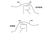
- FIG. 6 is a partially enlarged view showing the identification display 182 displayed on the sign 180 of the eyeglass member 110 in an enlarged manner.
- FIG. 6 shows an identification display 182 viewed from the user wearing the glasses 100 shown in FIG. 1 and an identification display 182 viewed from the side of the video observed by the user through the glasses 100.
- the letter “R” shown as the identification display 182 on the sign 180 has an asymmetric shape in the left-right direction. Therefore, the appearance of the identification display 182 differs between when viewed from the user side and when viewed from the video side. In particular, when viewed from the video side, the identification display 182 is displayed as a mirror image of the alphabet “R”.
- the operator who attaches the eyeglass member 110 can immediately recognize that the direction of the eyeglass member 110 is different.
- the glasses member 110 is attached to the frame 160 in the opposite direction, the user of the glasses 100 can immediately recognize that the direction of the glasses member 110 is different.
- the identification display 182 is formed as a set of open annular patterns that do not include a closed annular pattern. Therefore, even if the identification display 182 is formed by a cut or the like made in the spectacle member 110 itself, a cut-through portion does not occur and a section of the spectacle member 110 does not occur.
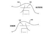
- FIG. 7 is a partially enlarged view illustrating another identification display 182 that can be displayed on the sign section 180 in an enlarged manner.
- FIG. 7 also shows an identification display 182 viewed from the user side wearing the glasses 100 shown in FIG. 1 and an identification display 182 viewed from the video side observed by the user through the glasses 100.
- an identification display 182 having the Chinese character “right” as a motif is displayed. Therefore, when viewed from the user side of the glasses 100, it is intuitively understood that the side on which the sign portion 180 is provided should be positioned on the right side when viewed from the user.
- the character “right” as the identification display 182 has an asymmetric shape in the left-right direction. Therefore, the view is different between when viewed from the user side and when viewed from the video side.
- the identification display 182 is displayed as a mirror image of the alphabet “right”, so it is easy to understand that the left and right of the eyeglass member 110 are different.
- the eyeglass member 110 is attached to the frame 160 in the opposite direction, it is easy to understand.
- the identification display 182 is formed as a set of open annular patterns that do not include a closed annular pattern.
- the identification display 182 is not limited to characters such as “R” or “right”. Further, the identification display 182 may be displayed by a figure, a color, or the like. Furthermore, the identification display 182 formed on the sign section 180 is not limited to a single character or a single symbol. The quality display, product name, manufacturer name, and handling precautions are displayed on the sign section 180 as the identification display 182. You may write.
- the labeling portion 180 may be disposed in either the right eye region 112 or the left eye region 114 of the eyeglass member 110. Further, the marker 180 may be formed so as to protrude outward in the surface direction of the spectacle member 110 along the outer periphery of the spectacle member 110, or a part of the outer periphery of the spectacle member 110 is cut out. May be formed. However, it is preferable to consider the arrangement so that the field of view as the glasses 100 is not narrowed by the sign part 180 and the identification display 182.
- FIG. 8 is a cross-sectional view of the identification display 182 in the sign section 180.
- the cross section shown in FIG. 7 shows a cross section that intersects one of the linear patterns forming the identification display 182.
- the identification display 182 is formed by a notch formed in the thickness direction of the marking portion 180.
- Such an incision can be formed by a half-cut process in which an incision is made shallower than the thickness of the eyeglass member 110. Therefore, by providing a cutting blade having the same shape as the pattern of the identification display 182 and having a different height on the cutting tool used when cutting the glasses member 110, the identification display 182 is provided simultaneously with the cutting processing of the glasses member 110. Can be formed.
- FIG. 9 is a cross-sectional view of another identification display 182 in the sign section 180.
- the cross section shown in FIG. 9 shows a cross section that intersects one of the linear patterns forming the identification display 182.
- the identification display 182 shown in the figure is formed by embossing the marking portion 180.
- the identification display 182 drawn with the thick line can be formed in the label
- the embossing can also be formed by press working using a mold, it can be formed by substantially the same equipment as that for cutting out the glasses member 110.
- the indicator 180 with the identification display 182
- the identification display 182 can be formed by the same equipment and process as the cutout or cutout of the eyeglass member 110 without using other equipment such as painting, printing, sticking, etc., by a method such as half-cutting or embossing.
- identification display 182 may be formed by printing, painting, transfer, or the like. Further, the identification display 182 may be formed by a seal, a sticker, or the like.
- FIG. 10 is a perspective view of glasses 200 according to another embodiment.
- the glasses 200 have the same structure as the glasses 100 shown in FIG. Therefore, the same reference numerals are assigned to elements common to the glasses 200, and redundant description is omitted.
- the glasses 200 include a glasses member 210 and a frame 260 that supports the glasses member 210.
- the glasses 200 have a shape of a part of the fitting projections 264 and 266 provided on the frame 260 and the fitting holes 117 and 119 corresponding to the fitting projections 264 and 266 provided on the glasses member 210. It has a structure different from that of the glasses 100 in terms of shape.
- the shapes of the fitting protrusions 264 and 266 will be described with reference to FIG.
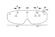
- FIG. 11 is a development view showing the glasses member 210 of the glasses 200 alone.
- the fitting hole 117 arranged in the right eye region 112 has a shape complementary to one fitting protrusion 264 of the frame 260.
- the fitting hole 119 disposed in the left eye region 114 has a shape complementary to the one fitting protrusion 266 of the frame 260.
- the entire width A of the fitting hole 117 formed in the right eye region 112 of the eyeglass member 210 is wider than the width B of the fitting hole 119 arranged in the left eye region 114 of the eyeglass member 210.
- a bridge portion 113 that connects the inside of the fitting hole 117 in the radial direction is provided vertically in the state shown in the drawing.
- the fitting protrusion 264 corresponding to the fitting hole 117 is provided with a groove 265 at a position complementary to the bridge portion 113.
- the fitting hole 117 whose center is blocked by the bridge portion 113 is formed.
- the fitting protrusion 266 cannot be fitted.
- the fitting protrusion 264 having a wide overall width A cannot be fitted into the fitting hole 119 having the narrow width B.
- some of the fitting protrusions 264 and 266 and the fitting holes 117 and 119 form a fitting prevention portion that prevents the fitting between the frame 260 and the glasses member 210. Accordingly, it is possible to prevent the eyeglass member 210 from being attached to the frame 260 in the wrong direction when attempting to attach the eyeglass member 210 in a direction different from a previously assumed direction.
- the glasses member 210 is not attached to the frame 260 in the wrong direction by the fitting prevention portions including the fitting protrusions 264 and 266 and the fitting holes 117 and 119. .
- the marker part 180 of the glasses member 210 may be omitted.
- the shape of the member 210 for glasses can be simplified and it can also make it easy to make the metal mold
- the eyeglass member 210 used for the eyeglasses 200 having the fitting prevention portion is also provided with the mark portion 180 including the identification display 182 that indicates the direction of the eyeglass member 210, the user has been wearing eyeglasses from the beginning. It is easy to recognize the correct orientation of the working member 210. Therefore, the number of times that the fitting of the glasses member 210 to the frame 260 is hindered by the fitting prevention portions including the fitting projections 264 and 266 and the fitting holes 117 and 119 is reduced, and the frame 260 of the glasses member 210 is reduced. Installation can be completed quickly.
- the fitting protrusions 264 and 266 are provided on the eyeglass member 210 side and the fitting holes 117 and 119 are provided on the frame 260, the same function as the glasses 200 shown in the figure can be realized.
- the number, shape, and arrangement of the fitting protrusions 264, 266 and the fitting holes 117, 119 are not limited to the above-described form.
- the marker 180 is provided so as to protrude from the upper side of the right eye region 112.
- the arrangement of the marker 180 is not limited to the upper side of the right eye region 112.
- the marker 180 may be provided at any location along the periphery of the eyeglass member 110 as long as it does not block the view of the user who uses the eyeglasses 100. Therefore, the sign part 180 may be provided on the side part of the member 110 for glasses, or may be provided in the lower part, for example. Further, a marker 180 may be provided in the left eye region 114.
- the marker part 180 in the glasses member 110 are different from the above example, it is preferable to arrange the marker part 180 inside the rectangle R inscribed with the right eye region 112 and the left eye region 114. . Thereby, the use efficiency fall of the material by having provided the label
- the shape of the sign portion 180 is not limited to the shape shown in the figure.
- the shape of the sign part 180 itself may be displayed or suggested by characters, symbols, etc. representing right and left or front and back.
- the shape of the right eye region 112 and the left eye region 114 for example, rounded corners may be made different from each other to form the marker portion 180.
- the marker 180 is not limited to the shape protruding from the eyeglass member 110, and may be a shape cut inward from the periphery of the eyeglass member 110, or may be a depressed portion.
- the structure of the sign part 180 itself is not limited to the above example.
- the sign part 180 may be added to the right eye region 112 and the left eye region 114 once manufactured in a symmetrical shape in a separate process.
- the material of the marking part 180 may be the same material as the right eye region 112 and the left eye region 114, or may be another material.
- the sign part 180 may be attached by an adhesive layer provided on the sign part 180, or may be fixed by adhesion, heat fusion or the like.
Landscapes
- Physics & Mathematics (AREA)
- Health & Medical Sciences (AREA)
- Ophthalmology & Optometry (AREA)
- General Physics & Mathematics (AREA)
- Optics & Photonics (AREA)
- General Health & Medical Sciences (AREA)
- Eyeglasses (AREA)
- Polarising Elements (AREA)
Abstract
L'invention concerne un élément pour lunettes qui est fixé de manière amovible sur une monture montée sur la tête d'un utilisateur, et qui est disposé devant les yeux de l'utilisateur lorsqu'il est monté sur la monture. L'élément pour lunettes comprend : une couche de modulation de polarisation d'œil droit ayant un premier axe optique et modulant la lumière polarisée dans la région de l'œil droit placée en face de l'œil droit de l'utilisateur ; une couche de modulation de polarisation d'œil gauche ayant un second axe optique différent du premier axe optique et modulant la lumière polarisée dans la région de l'œil gauche placée en face de l'œil gauche de l'utilisateur ; une couche de polarisation stratifiée sur à la fois la couche de modulation de polarisation de l'œil droit et la couche de modulation de polarisation de l'œil gauche, et ayant un axe d'absorption avec la même direction s'étendant dans la région de l'œil droit et la région de l'œil gauche ; et une section de repère pour indiquer une direction gauche/droite lorsqu'il est monté sur la monture.
Priority Applications (7)
| Application Number | Priority Date | Filing Date | Title |
|---|---|---|---|
| JP2016509200A JPWO2016157331A1 (ja) | 2015-03-27 | 2015-03-27 | メガネ用部材およびメガネ |
| EP15887484.2A EP3273291A4 (fr) | 2015-03-27 | 2015-03-27 | Élément pour lunettes et lunettes |
| CN201580077685.2A CN107407822A (zh) | 2015-03-27 | 2015-03-27 | 眼镜用部件及眼镜 |
| PCT/JP2015/059761 WO2016157331A1 (fr) | 2015-03-27 | 2015-03-27 | Élément pour lunettes et lunettes |
| TW106210792U TWM551704U (zh) | 2015-03-27 | 2016-03-10 | 眼鏡用構件及眼鏡 |
| TW105107347A TW201702691A (zh) | 2015-03-27 | 2016-03-10 | 眼鏡用構件及眼鏡 |
| US15/716,545 US20180017804A1 (en) | 2015-03-27 | 2017-09-27 | Eyeglass member and pair of eyeglasses |
Applications Claiming Priority (1)
| Application Number | Priority Date | Filing Date | Title |
|---|---|---|---|
| PCT/JP2015/059761 WO2016157331A1 (fr) | 2015-03-27 | 2015-03-27 | Élément pour lunettes et lunettes |
Related Child Applications (1)
| Application Number | Title | Priority Date | Filing Date |
|---|---|---|---|
| US15/716,545 Continuation US20180017804A1 (en) | 2015-03-27 | 2017-09-27 | Eyeglass member and pair of eyeglasses |
Publications (1)
| Publication Number | Publication Date |
|---|---|
| WO2016157331A1 true WO2016157331A1 (fr) | 2016-10-06 |
Family
ID=57004870
Family Applications (1)
| Application Number | Title | Priority Date | Filing Date |
|---|---|---|---|
| PCT/JP2015/059761 Ceased WO2016157331A1 (fr) | 2015-03-27 | 2015-03-27 | Élément pour lunettes et lunettes |
Country Status (6)
| Country | Link |
|---|---|
| US (1) | US20180017804A1 (fr) |
| EP (1) | EP3273291A4 (fr) |
| JP (1) | JPWO2016157331A1 (fr) |
| CN (1) | CN107407822A (fr) |
| TW (2) | TWM551704U (fr) |
| WO (1) | WO2016157331A1 (fr) |
Citations (8)
| Publication number | Priority date | Publication date | Assignee | Title |
|---|---|---|---|---|
| JPS6219620U (fr) * | 1985-07-22 | 1987-02-05 | ||
| JPH05504849A (ja) * | 1990-12-11 | 1993-07-22 | グレンデルマイアー、アレキサンダー | 眼鏡 |
| JP2011138108A (ja) * | 2009-12-01 | 2011-07-14 | Minoru Inaba | 立体映像観賞用メガネ |
| JP2011197629A (ja) * | 2010-02-23 | 2011-10-06 | Yamamoto Kogaku Co Ltd | 円偏光板および円偏光レンズ、および円偏光眼鏡 |
| JP2012088369A (ja) * | 2010-10-15 | 2012-05-10 | Toshiba Mobile Display Co Ltd | 眼鏡用液晶シャッタセット及びその製造方法 |
| JP2013501443A (ja) * | 2009-08-06 | 2013-01-10 | ソニー ヨーロッパ リミテッド | 3d画像表示方法、3d画像表示装置、シャッターメガネ、プログラムおよびコンピュータ可読記録媒体 |
| JP2013016961A (ja) * | 2011-07-01 | 2013-01-24 | Sanyo Electric Co Ltd | 3dメガネ、および3dメガネセット |
| JP2014199301A (ja) * | 2013-03-29 | 2014-10-23 | 株式会社有沢製作所 | メガネ用部材、メガネおよびメガネ用部材の製造方法 |
Family Cites Families (7)
| Publication number | Priority date | Publication date | Assignee | Title |
|---|---|---|---|---|
| US5062701A (en) * | 1988-06-07 | 1991-11-05 | Wesley-Jessen Corporation | Asymmetric contact lens |
| US7188947B1 (en) * | 2006-03-22 | 2007-03-13 | Chin-Jen Chen | Lens combined with a soft eyeglasses rim |
| US7524053B2 (en) * | 2006-05-12 | 2009-04-28 | Real D | 3-D eyewear |
| WO2012078197A1 (fr) * | 2010-01-22 | 2012-06-14 | Oakley, Inc. | Article de lunetterie assurant une vision en trois dimensions |
| JP2011257454A (ja) * | 2010-06-04 | 2011-12-22 | Sony Corp | シャッター眼鏡 |
| SG187802A1 (en) * | 2010-08-13 | 2013-03-28 | Oakley Inc | Eyewear with lens retention mechanism |
| CN105204105A (zh) * | 2014-06-12 | 2015-12-30 | 株式会社有泽制作所 | 眼镜用部件、眼镜及眼镜用部件的制造方法 |
-
2015
- 2015-03-27 EP EP15887484.2A patent/EP3273291A4/fr not_active Withdrawn
- 2015-03-27 WO PCT/JP2015/059761 patent/WO2016157331A1/fr not_active Ceased
- 2015-03-27 JP JP2016509200A patent/JPWO2016157331A1/ja active Pending
- 2015-03-27 CN CN201580077685.2A patent/CN107407822A/zh active Pending
-
2016
- 2016-03-10 TW TW106210792U patent/TWM551704U/zh unknown
- 2016-03-10 TW TW105107347A patent/TW201702691A/zh unknown
-
2017
- 2017-09-27 US US15/716,545 patent/US20180017804A1/en not_active Abandoned
Patent Citations (8)
| Publication number | Priority date | Publication date | Assignee | Title |
|---|---|---|---|---|
| JPS6219620U (fr) * | 1985-07-22 | 1987-02-05 | ||
| JPH05504849A (ja) * | 1990-12-11 | 1993-07-22 | グレンデルマイアー、アレキサンダー | 眼鏡 |
| JP2013501443A (ja) * | 2009-08-06 | 2013-01-10 | ソニー ヨーロッパ リミテッド | 3d画像表示方法、3d画像表示装置、シャッターメガネ、プログラムおよびコンピュータ可読記録媒体 |
| JP2011138108A (ja) * | 2009-12-01 | 2011-07-14 | Minoru Inaba | 立体映像観賞用メガネ |
| JP2011197629A (ja) * | 2010-02-23 | 2011-10-06 | Yamamoto Kogaku Co Ltd | 円偏光板および円偏光レンズ、および円偏光眼鏡 |
| JP2012088369A (ja) * | 2010-10-15 | 2012-05-10 | Toshiba Mobile Display Co Ltd | 眼鏡用液晶シャッタセット及びその製造方法 |
| JP2013016961A (ja) * | 2011-07-01 | 2013-01-24 | Sanyo Electric Co Ltd | 3dメガネ、および3dメガネセット |
| JP2014199301A (ja) * | 2013-03-29 | 2014-10-23 | 株式会社有沢製作所 | メガネ用部材、メガネおよびメガネ用部材の製造方法 |
Non-Patent Citations (1)
| Title |
|---|
| See also references of EP3273291A4 * |
Also Published As
| Publication number | Publication date |
|---|---|
| US20180017804A1 (en) | 2018-01-18 |
| TWM551704U (zh) | 2017-11-11 |
| JPWO2016157331A1 (ja) | 2018-01-18 |
| CN107407822A (zh) | 2017-11-28 |
| EP3273291A4 (fr) | 2018-10-24 |
| TW201702691A (zh) | 2017-01-16 |
| EP3273291A1 (fr) | 2018-01-24 |
Similar Documents
| Publication | Publication Date | Title |
|---|---|---|
| JP5272122B2 (ja) | 光学素子アレイシート、表示装置、及びこれらの製造方法 | |
| JP6364936B2 (ja) | 画像表示装置 | |
| CN103293755B (zh) | 立体显示装置 | |
| JPWO2008142846A1 (ja) | 立体画像表示装置 | |
| US10133071B2 (en) | Replaceable optical element for near eye display | |
| WO2015170716A1 (fr) | Dispositif de protection de lunettes | |
| JP2012032445A (ja) | 積層体の製造方法、位相差板の製造方法および位相差板 | |
| KR20160100004A (ko) | 표시 장치 | |
| CN110088668A (zh) | 镜片及眼睛佩戴物 | |
| CN111458875A (zh) | 光学成像装置 | |
| US10310165B2 (en) | Image display apparatus | |
| JP2013083784A (ja) | 偏光フィルムの貼付方法 | |
| BR112014022446B1 (pt) | Sistema para a visualização estereoscópica de informação de imagem, óculos para a visualização de imagens tridimensionais e processo para visualização de informação de imagem estereoscópica | |
| WO2016157331A1 (fr) | Élément pour lunettes et lunettes | |
| JP6441103B2 (ja) | 画像表示装置 | |
| JP2023057103A (ja) | ヘッドマウントディスプレイ | |
| JP2014199301A (ja) | メガネ用部材、メガネおよびメガネ用部材の製造方法 | |
| JP2003167216A (ja) | 3d映像表示装置及び3d映像表示装置用の偏光メガネ | |
| JP4906777B2 (ja) | 装用確認用シート | |
| KR101106774B1 (ko) | 입체 디스플레이 장치 및 그 제조 방법 | |
| WO2026096778A1 (fr) | Ébauches de guides d'ondes ophtalmiques pour systèmes d'affichage | |
| JP4300886B2 (ja) | 立体視用ビュアー | |
| JP6488870B2 (ja) | 光学レンズの製造方法 | |
| KR20130054704A (ko) | 시역 분리용 기판, 이를 포함한 입체 영상 디스플레이 장치 및 시역 분리용 기판의 제조방법 | |
| US20150370083A1 (en) | Wearable stereoscopic viewer |
Legal Events
| Date | Code | Title | Description |
|---|---|---|---|
| ENP | Entry into the national phase |
Ref document number: 2016509200 Country of ref document: JP Kind code of ref document: A |
|
| 121 | Ep: the epo has been informed by wipo that ep was designated in this application |
Ref document number: 15887484 Country of ref document: EP Kind code of ref document: A1 |
|
| NENP | Non-entry into the national phase |
Ref country code: DE |
|
| REEP | Request for entry into the european phase |
Ref document number: 2015887484 Country of ref document: EP |