WO2016157397A1 - 電子機器の冷却システム - Google Patents
電子機器の冷却システム Download PDFInfo
- Publication number
- WO2016157397A1 WO2016157397A1 PCT/JP2015/060032 JP2015060032W WO2016157397A1 WO 2016157397 A1 WO2016157397 A1 WO 2016157397A1 JP 2015060032 W JP2015060032 W JP 2015060032W WO 2016157397 A1 WO2016157397 A1 WO 2016157397A1
- Authority
- WO
- WIPO (PCT)
- Prior art keywords
- coolant
- cooling
- heat exchanger
- cooling system
- boiling point
- Prior art date
- Legal status (The legal status is an assumption and is not a legal conclusion. Google has not performed a legal analysis and makes no representation as to the accuracy of the status listed.)
- Ceased
Links
Images


Classifications
-
- H—ELECTRICITY
- H05—ELECTRIC TECHNIQUES NOT OTHERWISE PROVIDED FOR
- H05K—PRINTED CIRCUITS; CASINGS OR CONSTRUCTIONAL DETAILS OF ELECTRIC APPARATUS; MANUFACTURE OF ASSEMBLAGES OF ELECTRICAL COMPONENTS
- H05K7/00—Constructional details common to different types of electric apparatus
- H05K7/20—Modifications to facilitate cooling, ventilating, or heating
- H05K7/20709—Modifications to facilitate cooling, ventilating, or heating for server racks or cabinets; for data centers, e.g. 19-inch computer racks
- H05K7/208—Liquid cooling with phase change
- H05K7/20818—Liquid cooling with phase change within cabinets for removing heat from server blades
-
- F—MECHANICAL ENGINEERING; LIGHTING; HEATING; WEAPONS; BLASTING
- F28—HEAT EXCHANGE IN GENERAL
- F28D—HEAT-EXCHANGE APPARATUS, NOT PROVIDED FOR IN ANOTHER SUBCLASS, IN WHICH THE HEAT-EXCHANGE MEDIA DO NOT COME INTO DIRECT CONTACT
- F28D15/00—Heat-exchange apparatus with the intermediate heat-transfer medium in closed tubes passing into or through the conduit walls ; Heat-exchange apparatus employing intermediate heat-transfer medium or bodies
- F28D15/02—Heat-exchange apparatus with the intermediate heat-transfer medium in closed tubes passing into or through the conduit walls ; Heat-exchange apparatus employing intermediate heat-transfer medium or bodies in which the medium condenses and evaporates, e.g. heat pipes
-
- G—PHYSICS
- G06—COMPUTING OR CALCULATING; COUNTING
- G06F—ELECTRIC DIGITAL DATA PROCESSING
- G06F1/00—Details not covered by groups G06F3/00 - G06F13/00 and G06F21/00
- G06F1/16—Constructional details or arrangements
- G06F1/20—Cooling means
-
- H—ELECTRICITY
- H05—ELECTRIC TECHNIQUES NOT OTHERWISE PROVIDED FOR
- H05K—PRINTED CIRCUITS; CASINGS OR CONSTRUCTIONAL DETAILS OF ELECTRIC APPARATUS; MANUFACTURE OF ASSEMBLAGES OF ELECTRICAL COMPONENTS
- H05K7/00—Constructional details common to different types of electric apparatus
- H05K7/20—Modifications to facilitate cooling, ventilating, or heating
-
- H—ELECTRICITY
- H05—ELECTRIC TECHNIQUES NOT OTHERWISE PROVIDED FOR
- H05K—PRINTED CIRCUITS; CASINGS OR CONSTRUCTIONAL DETAILS OF ELECTRIC APPARATUS; MANUFACTURE OF ASSEMBLAGES OF ELECTRICAL COMPONENTS
- H05K7/00—Constructional details common to different types of electric apparatus
- H05K7/20—Modifications to facilitate cooling, ventilating, or heating
- H05K7/20218—Modifications to facilitate cooling, ventilating, or heating using a liquid coolant without phase change in electronic enclosures
- H05K7/20236—Modifications to facilitate cooling, ventilating, or heating using a liquid coolant without phase change in electronic enclosures by immersion
-
- H—ELECTRICITY
- H05—ELECTRIC TECHNIQUES NOT OTHERWISE PROVIDED FOR
- H05K—PRINTED CIRCUITS; CASINGS OR CONSTRUCTIONAL DETAILS OF ELECTRIC APPARATUS; MANUFACTURE OF ASSEMBLAGES OF ELECTRICAL COMPONENTS
- H05K7/00—Constructional details common to different types of electric apparatus
- H05K7/20—Modifications to facilitate cooling, ventilating, or heating
- H05K7/20709—Modifications to facilitate cooling, ventilating, or heating for server racks or cabinets; for data centers, e.g. 19-inch computer racks
- H05K7/20763—Liquid cooling without phase change
-
- H—ELECTRICITY
- H10—SEMICONDUCTOR DEVICES; ELECTRIC SOLID-STATE DEVICES NOT OTHERWISE PROVIDED FOR
- H10W—GENERIC PACKAGES, INTERCONNECTIONS, CONNECTORS OR OTHER CONSTRUCTIONAL DETAILS OF DEVICES COVERED BY CLASS H10
- H10W40/00—Arrangements for thermal protection or thermal control
- H10W40/40—Arrangements for thermal protection or thermal control involving heat exchange by flowing fluids
- H10W40/47—Arrangements for thermal protection or thermal control involving heat exchange by flowing fluids by flowing liquids, e.g. forced water cooling
-
- G—PHYSICS
- G06—COMPUTING OR CALCULATING; COUNTING
- G06F—ELECTRIC DIGITAL DATA PROCESSING
- G06F2200/00—Indexing scheme relating to G06F1/04 - G06F1/32
- G06F2200/20—Indexing scheme relating to G06F1/20
- G06F2200/201—Cooling arrangements using cooling fluid
Definitions
- the present invention relates to a cooling system for electronic devices, and more particularly to efficiently cool electronic devices that require super-high performance operation and stable operation such as supercomputers and data centers and generate a large amount of heat from itself.
- the present invention relates to a cooling system for electronic equipment.
- the cooling system disclosed in Patent Document 1 uses a fluorocarbon coolant having a boiling point of 100 ° C. or lower because it uses heat of vaporization (latent heat) to cool electronic devices. Then, the heat of the element is taken by the heat of vaporization (latent heat) when the coolant evaporates due to the heat generated by the element mounted on the electronic device, and the element is cooled. Accordingly, the fluorocarbon-based coolant may boil locally on the surface of the high-temperature element and bubbles may form a heat insulating film, so that the high heat conduction ability inherent in the coolant is impaired. There is a problem.
- the target to be cooled is not only CPU (Central Processing Unit) but also GPU (Graphics Processing Unit), high-speed memory, chipset, network unit, There are many PCI Express buses, bus switch units, SSDs (Solid State Drives), power units (AC-DC converters, DC-DC voltage converters, etc.) and all these objects with different vaporization temperatures. Are equally difficult to cool, and the cooling efficiency is extremely low for an object whose surface refrigerant does not evaporate.
- the cooling system disclosed in Patent Document 2 adopts a configuration of a sealed module that houses one or more heat-generating electronic devices. For this reason, the entire mechanism for circulating the coolant through the individual sealed modules is complicated, and the entire electronic device cannot be easily taken out from the sealed module, resulting in poor maintenance of the electronic device. is there.
- the conventional immersion cooling method has a problem that the entire mechanism for circulating the coolant through the sealed module is complicated, and the maintainability of the electronic device is inferior.
- an object of the present invention is to provide a simple and efficient cooling system that solves the above-mentioned problems of the prior art and improves the cooling performance of electronic equipment.
- a cooling system that directly cools an electronic device by immersing it in a cooling liquid, the cooling system having an open space formed by a bottom wall and a side wall.
- a cooling bath in which a first coolant having a boiling point T 1 is placed and at least one electronic device having at least one heating element is immersed in the first coolant and directly cooled.
- the first cooling liquid contains a fully fluorinated product as a main component, and 10 ml of liquid is placed in a 10 ml graduated cylinder (opening diameter: 11.5 mm) at a room temperature of 25. You may comprise so that the liquid weight reduction
- the first coolant may be configured so that the vapor pressure at room temperature of 25 ° C. is 1.0 kPa or less.
- the first coolant may have a boiling point of 150 ° C. or higher and the second refrigerant may have a boiling point of 50 ° C. or lower.
- the second refrigerant may be configured to contain a fluorocarbon compound as a main component.
- the cooling system further comprises a second heat exchanger that is placed outside the cooling tank and cools the second refrigerant,
- the heat exchanger and the second heat exchanger may be connected by a first flow path.
- the cooling tank has a top plate attached to the upper opening of the cooling tank so as to be detachable or openable.
- One heat exchanger may be held.
- the cooling tank has an inlet and an outlet for the first cooling liquid, and the outlet and the inlet are outside the cooling tank.
- the flow path may be provided with at least one pump for moving the first coolant and a third heat exchanger for cooling the first coolant. .
- a cooling system for directly cooling a plurality of electronic devices by immersing them in a cooling liquid, the cooling tank having an open space formed by a bottom wall and a side wall.
- a storage portion for storing at least one electronic device in each storage portion; and an inlet opening and an outlet opening for the first coolant formed in each of the plurality of storage portions;
- the main heat source such as a processor mounted on an electronic device in which the first cooling liquid containing the first cooling liquid having the boiling point T 1 is immersed. And the surrounding electronic components are effectively cooled.
- immersion cooling of the main heating element and the entire surrounding electronic components by the first cooling liquid in the cooling tank having the open space, and immersion refrigerant by the first heat exchanger (first The cooling performance of the electronic device can be improved by performing double cooling including heat removal from the surface layer portion of the coolant.
- a coolant having a relatively high boiling point can be used as the first coolant, the first coolant is unlikely to evaporate, and the cooling tank into which the first coolant is placed is an unsealed open space.
- the volume occupied by the components in the cooling tank can be reduced.
- the cooling tank having the “open space” in the present specification includes a cooling tank having a simple sealed structure that does not impair maintainability of the electronic device.
- a structure in which the top plate is attached to the opening of the cooling tank via a packing or the like so as to be detachable or openable can be said to be a simple sealed structure.
- the first heat exchanger since it is only necessary to immerse the first heat exchanger in the surface layer portion of the first coolant, the first heat exchanger can be mechanically held on the top plate.
- FIGS. 1 to 3 a preferred embodiment will be described with reference to FIGS. 1 to 3, in which three processor boards each equipped with a CPU or GPU processor are arranged on one surface of the board.
- a configuration of a main part of the cooling system that houses and cools the electronic device in the cooling tank will be described.
- FIG. 4 an entire configuration of a cooling system that houses and cools the electronic device in a cooling tank will be described while simply showing only one unit of the electronic device having the same structure.
- a cooling system 10 includes a cooling tank 12, and a first cooling liquid 13 having a boiling point T 1 is placed in an open space of the cooling tank 12.
- a processor board 110 with a CPU and two processor boards 112 with a GPU are placed on one side and the other side of the board 120.
- the mounted electronic device 100 is accommodated and immersed in the first coolant 13.
- the processor boards 110 and 112 include heat radiating members (heat radiating fins) 114 that are thermally connected to the processor.
- peripheral electronic components are naturally mounted on the processor boards 110 and 112 and the board 120 of the electronic device 100, but these electronic components are not shown.
- the liquid level 19 of the first coolant 13 is maintained such that the CPU and peripheral electronic components, which are main heating elements of the electronic device 100, are all immersed in the first coolant 13. It is. As will be described later, according to a preferred embodiment, the liquid level 19 is maintained for a long period of time because the first cooling liquid 13 has the property of hardly evaporating.
- the first coolant 13, higher than the boiling point T 2 of the same or a second refrigerant boiling T 2 of the second refrigerant which is sealed in the first heat exchanger to be described later it is important to select a refrigerant having a boiling point T 1.
- HFE hydrofluoroether
- the present inventor is a compound in which a fully fluorinated product has high electrical insulation and high heat transfer ability, is inert, has high thermal and chemical stability, is nonflammable, and does not contain oxygen. Therefore, paying attention to the excellent characteristics such as zero ozone depletion coefficient, a coolant containing such a fully fluorinated product as a main component is used as a coolant for immersion cooling of high-density electronic equipment.
- the invention of the cooling system to be used has been completed and a patent application has been filed (Japanese Patent Application No. 2014-170616).
- the first coolant containing such a perfluorinated compound as a main component is placed in a 10 ml measuring cylinder (opening diameter: 11.5 mm) under a normal environment at a room temperature of 25 ° C.
- the first cooling liquid 13 is difficult to evaporate even when the cooling tank 12 is an unsealed open space. Therefore, the loss due to evaporation of the first coolant 13 can be greatly reduced.
- the vapor pressure of the first coolant 13 at room temperature 25 ° C. is 1.0 kPa or less, or when the boiling point of the first coolant 13 is 150 ° C.
- the fully fluorinated product contained as the main component is a fully fluorinated product having 10 or more carbon atoms, similarly, even when the cooling tank 12 is an unsealed open space, the first coolant 13 is unlikely to evaporate. The loss due to evaporation of the first coolant can be greatly reduced.
- FIG. 3 shows the weight loss rate after 100 hours, the weight loss rate after 1000 hours, the vapor pressure, the boiling point, and the number of main component carbons for FC-43, FC-40, FC-3283, and FC-770. And a table comparing molecular weights.
- the first coolant 13 is the same as the boiling point T2 of the second refrigerant sealed in the first heat exchanger described later or the second refrigerant. It goes without saying that the selection of any one of Fluorinert FC-72, FC-770, and FC-3283 as the coolant having the boiling point T 1 higher than the boiling point T 2 is not limited.
- the top plate 20 provided in the upper opening of the cooling tank 12 is used for maintenance of the electronic device 100. It may be attached to the upper opening so as to be detachable or openable and closable so that it can be easily performed.
- the top plate 20 may be supported by a hinge portion (not shown) provided at one edge of the upper opening of the cooling bath 12 so as to be freely opened and closed.
- An inlet 16 through which the first coolant flows is provided below the side of the cooling tank 12, and an outlet 18 through which the first coolant flows out above the side of the cooling tank 12. Is provided.
- the electronic device 100 accommodated in the open space of the cooling bath 12 is configured to be directly cooled by being immersed in the first coolant 13 flowing in the open space of the cooling bath 12.
- the cooling system 10 further includes a first heat exchanger 22 that is mechanically held by the top plate 20, and the first heat exchanger 22 is a first heat exchanger 22. It is immersed in the surface layer portion in the coolant 13.
- the mechanical holding method of the 1st heat exchanger 22 may use the suspension support member (not shown) fixed to the top plate 20, for example, it is not limited to this.
- “enclosed” means that the second refrigerant does not leak into the outside air, and the second refrigerant is separated from the first heat exchanger to other components (for example, a later-described first component). It is not limited to move to the second heat exchanger) or to circulate between the first heat exchanger and other components.
- 3M's trade names “Novec 7000” (boiling point 34 ° C.), “Novec 7100” (boiling point 61 ° C.), “Novec 7200” (boiling point 76 ° C.), “Novec 7300” (boiling point 98 ° C.) are known.
- Hydrofluoroether (HFE) compounds can be preferably used, but are not limited thereto.
- a refrigerant having a boiling point T 2 that is the same as the boiling point T 1 of the first coolant 13 or lower than the boiling point T 1 of the first coolant 13 may be selected as the second coolant.
- “Fluorinert FC-40” (boiling point 155 ° C.) is used as the first coolant 13
- “Novec 7000” (boiling point 34 ° C.) or “Novec 7100” (boiling point 61 ° C.) is suitable as the second refrigerant.
- the cooling system 10 may further include a second heat exchanger 24 placed outside the cooling bath 12.
- the first heat exchanger 22 and the second heat exchanger 24 are connected by a first flow path 26, and the second refrigerant passes through the first flow path 26 and performs the first heat exchange. It can be moved or circulated between the heat exchanger 22 and the second heat exchanger 24.
- As the first heat exchanger it is preferable to use a thin heat exchanger so as to be immersed in the surface layer portion in the first coolant 13. For example, a coil shape or a spiral shape as shown in FIG.
- the heat exchanger may be a heat exchanger composed of a meandered tube, but the structure of the heat exchanger (plate type heat exchanger, plate and fin type heat exchanger, etc.) is not limited.
- the second heat exchanger 24 may be any heat exchanger that cools the second refrigerant moving from the first heat exchanger 22 to the second heat exchanger 24.
- a cooler radiator or chiller
- cooler may be used.
- the outlet 18 and the inlet 16 of the cooling tank 12 are connected by a second flow passage 30, and a pump 40 that moves the first coolant 13 into the second flow passage 30.
- a third heat exchanger 90 for cooling the first coolant 13 is provided.
- a flow rate adjusting valve 50 and a flow meter 70 for adjusting the flow rate of the first coolant 13 flowing through the second flow passage 30 are also provided in the second flow passage 30.
- the pump 40 preferably has a performance of moving a liquid having a relatively large kinematic viscosity (a kinematic viscosity at room temperature of 25 ° C. exceeds 3 cSt).
- a kinematic viscosity at room temperature of 25 ° C. exceeds 3 cSt For example, when Fluorinert FC-43 or FC-40 is used as the first coolant 13, the kinematic viscosity of FC-43 is about 2.5 to 2.8 cSt, and the kinematic viscosity of FC-40 is 1. This is because it is about 8 to 2.2 cSt.
- the flow rate adjustment valve 50 may be manually operated, or may be provided with an adjustment mechanism that keeps the flow rate constant based on the measurement value of the flow meter 70.
- the third heat exchanger 90 may be various circulation heat exchangers (a radiator or a chiller) or a cooler.
- the first coolant 13 for example, Fluorinert FC-43 around the electronic device 100 is transferred to the processor mounted on the processor boards 110 and 112 and peripheral electronic components ( The electronic equipment is entirely cooled by taking heat directly or through the heat dissipation member 114 (not shown).
- First heat exchanger 22 where a second refrigerant having a low boiling point T 2 than the boiling point T 1 of the boiling point T 1 and the same or a first coolant 13 is sealed in the first coolant 13, cooled Since it is immersed in the surface layer part in the 1st cooling liquid 13 in the tank 12, the heat
- FIG. In this manner, the main heating element and the entire surrounding electronic components (not shown) are immersed and cooled by the first coolant 13 in the cooling tank 12 having the open space, and the first heat exchanger 22 is provided.
- the cooling performance of the electronic device 100 can be improved by performing double cooling including heat removal from the surface portion of the immersion refrigerant (first cooling liquid 13).
- a coolant having a relatively high boiling point for example, Fluorinert FC-43 or FC-40 has a boiling point of 150 ° C. or higher
- FC-43 or FC-40 has a boiling point of 150 ° C. or higher
- the cooling tank 12 into which the first coolant 13 is put may be an unsealed open space, and it is not necessary to adopt a complicated and expensive sealing structure.
- the first heat exchanger 22 since the first heat exchanger 22 only needs to be immersed in the surface layer portion of the first coolant 13, the volume occupied by the components in the cooling bath 12 can be small. Therefore, simplification and miniaturization of the cooling system are realized.
- a high-density cooling system that cools one unit including a board 120 on which a plurality of processor boards 110 and 112 are mounted as electronic devices in a total of 16 units in each storage section of the cooling tank.
- the structure of will be described. This is merely an example, the number of processor boards per board and the type of processor (CPU or GPU) are arbitrary, and the number of electronic device units in the high-density cooling system is also arbitrary.
- the configuration of the electronic device is not limited.
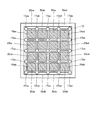
- a cooling system 500 includes a cooling tank 12, and an open space 10a is formed by a bottom wall 12a and a side wall 12b of the cooling tank 12.
- an open space 10a is formed by a bottom wall 12a and a side wall 12b of the cooling tank 12.
- storage unit 15aa 16 storage units 15aa, 15ab, 15ac, 15ad, 15ba, 15bb, 15bc, 15bd, 15ca, 15cb, 15cc, 15cd, 15da, 15db, 15dc, 15dd (hereinafter collectively referred to as “storage unit 15aa”) May be described as “ ⁇ 15dd”). And at least 1 electronic device 100 is accommodated in each accommodating part. In the open space 10 a of the cooling tank 12, the first coolant 13 is put up to the liquid level 19.
- the inlets 16aa, 16ab of the first coolant 13 are formed at the bottom of the storage portions 15aa, 15ab, 15ac, 15ad, 15ba, 15bb, 15bc, 15bd, 15ca, 15cb, 15cc, 15cd, 15da, 15db, 15dc, 15dd.
- 16ac, 16ad, 16ba, 16bb, 16bc, 16bd, 16ca, 16cb, 16cc, 16cd, 16da, 16db, 16dc, 16dd (hereinafter may be collectively referred to as “inflow openings 16aa to 16dd”).
- inflow openings 16aa to 16dd has been.
- the outflow openings 17aa, 17ab, 17ac, 17ad, 17ae, 17ba, 17bb, 17bc, 17bd, 17be, 17ca, 17cb, 17 cc, 17 cd, 17 ce, 17 da, 17 db, 17 dc, 17 dd, 17 de, 17 ea, 17 eb, 17 ec, 17 ed, 17 ee (hereinafter sometimes collectively referred to as “outflow openings 17 aa to 17 ee”) are formed. .
- the outflow opening is formed at or near a position where a plurality of internal partition walls forming each storage portion intersect each other.
- the storage portion 15aa is formed by vertical internal partition walls 13a and 13b and horizontal internal partition walls 14a and 14b, and the internal partition wall 13a and the internal partition wall 14a intersect each other.
- Outflow openings 17aa, 17ba, 17ab, so as to be located at a point where the partition wall 13a and the inner partition wall 14b intersect, a point where the inner partition wall 13b and the inner partition wall 14a intersect, and a point where the inner partition wall 13b and the inner partition wall 14b intersect, respectively. 17bb is formed.
- FIG. 1 is formed by vertical internal partition walls 13a and 13b and horizontal internal partition walls 14a and 14b, and the internal partition wall 13a and the internal partition wall 14a intersect each other.
- Outflow openings 17aa, 17ba, 17ab so as to be located at a point where the partition wall 13a and the inner partition wall 14b intersect
- the storage portion 15bb is formed by the vertical inner partition walls 13b and 13c and the horizontal inner partition walls 14b and 14c, and the inner partition wall 13b and the inner partition wall 14b intersect.
- the outflow openings 17bb, 17cb are respectively positioned at the point where the internal partition wall 13b and the internal partition wall 14c intersect, the point where the internal partition wall 13c and the internal partition wall 14b intersect, and the point where the internal partition wall 13c and the internal partition wall 14c intersect. 17bc and 17cc are formed.
- the outflow opening is formed at one end of an outflow pipe 170 that extends through the bottom wall 12a of the cooling tank 12 to the vicinity of the liquid surface 19.
- the outflow openings 17bb, 17cb, 17bc, 17cc are formed by vertical internal partition walls 13b, 13c and horizontal internal partition walls 14b, 14c. 13b and the inner partition wall 14b intersect, the inner partition wall 13b and the inner partition wall 14c intersect, the inner partition wall 13c and the inner partition wall 14b intersect, and the inner partition wall 13c and the inner partition wall 14c intersect, respectively. It is formed at one end of the outflow pipe 170.
- the other end of the outflow pipe has a bottom opening 18aa, 18ab, 18ac, 18ad, 18ae, 18ba, 18bb, 18bc, 18bd, 18be, 18ca, 18cb, 18cc, 18cd, 18ce, 18da, 18db, 18dc, 18dd, 18de, 18ea, 18eb, 18ec, 18ed, and 18ee (hereinafter, collectively referred to as “bottom openings 18aa to 18ee”) are formed.
- outflow openings 17bb, 17bc, 17cb, and 17cc are formed by the outflow pipes 170 arranged at the four corners.
- the outflow opening 17bb is a part of the outflow opening for the storage part 15aa and at the same time a part of the outflow opening for the storage parts 15ab, 15ba, and 15bb.
- outflow openings 17bc, 17cb, and 17cc are arbitrary, and one or a plurality of outflow pipes may be provided in the vicinity of a position where a plurality of internal partition walls forming each storage part intersect each other.
- the outflow pipe does not need to be integrated with the internal partition, and may be a pipe disposed away from the internal partition.
- one or more small holes 171 may be formed in the outflow pipe 170 in the longitudinal direction of the outflow pipe 170. These small holes 171 promote the circulation of the first coolant 13 in the middle of the storage portion in the depth direction.
- the inflow openings 16aa to 16dd do not need to be cylindrical openings as shown in the figure.
- a header having a plurality of nozzles is connected to one end of the cylinder to form inflow openings by a number of nozzles. May be.
- the electronic device 100 is stored and immersed in the first coolant 13.
- the electronic device 100 is the same as the electronic device in the previous embodiment, and a detailed description thereof is omitted here.
- the first coolant 13 is the same as the first coolant in the previous embodiment, and a detailed description thereof is omitted here.
- the cooling tank 12 has an inlet 16 for distributing the first coolant 13 through distribution pipes (not shown) toward the inflow openings 16aa to 16dd provided in the storage portions 15aa to 15dd, and An outlet 18 is provided for collecting the first coolant 13 that has passed through the outflow openings 17aa to 17ee of the storage portions 15aa to 15dd via a collecting pipe (not shown).
- the first cooling liquid 13 cooled to a desired temperature is continuously supplied to each of the storage units 15aa to 15aa so that the electronic device 100 stored in each of the storage units 15aa to 15dd is kept at a predetermined temperature or lower during operation.
- the second coolant 13 that has exited from the outlet 18 of the cooling tank 12 is cooled by a heat exchanger, and the cooled coolant is returned to the inlet 16 of the cooling tank 12.
- a flow passage may be configured. Since an example of such a flow path and the accompanying equipment has already been described in detail with reference to FIG. 4, description thereof is omitted here.
- Each of the distributed first heat exchangers 22aa to 22dd is immersed in the surface layer portion of the first coolant 13 in each of the storage portions 15aa to 15dd.
- Each of the distributed first heat exchangers 22aa to 22dd may be mechanically held on a top plate (not shown), similarly to the first heat exchanger in one embodiment.
- Each of the distributed first heat exchangers 22aa to 22dd is similar to the example shown in FIG. 1 in that the second heat exchanger placed outside the cooling tank 12 and the first flow path ( (Not shown).
- the same number of second heat exchangers as the distributed first heat exchangers 22aa to 22dd are prepared and individually connected, and the distributed first heat exchangers 22aa to 22dd are A method in which one group is divided into a plurality of (for example, four) groups of several (for example, four) heat exchangers, and a second heat exchanger is prepared for each group and individually connected, or Any of the methods of connecting one second heat exchanger to all the distributed first heat exchangers 22aa to 22dd may be used.
- the first coolant 13 entering from the inlet 16 is distributed toward inflow openings 16aa to 16dd formed at the bottoms of the storage portions 15aa to 15dd through a distribution pipe (not shown).
- the first coolant 13 blows upward from the inflow openings 16aa to 16dd, and is mounted from the processors on the processor boards 110 and 112 and peripheral electronic components (not shown) mounted on the board 120 of the electronic device 100.
- the electronic device is entirely cooled.
- the first cooling liquid 13 blows up from the inflow opening 16bb
- the first cooling liquid 13 rises toward the liquid level 19 while taking heat from the surfaces of the processors on the processor boards 110 and 112 and peripheral electronic components (not shown). Furthermore, it moves toward the outflow openings 17bb, 17bc, 17cb, and 17cc.
- the volume of the storage portions 15aa to 15dd is as small as about 1/16 of the volume of the open space 10a of the cooling bath 12, and the electronic device 100 stored therein is also about 1 / of the width of the cooling bath 12. Therefore, the cooling efficiency of the electronic device 100 by the first coolant 13 is extremely good, and the first coolant 13 can be effectively prevented from staying around the electronic device 100.
- each of the distributed first heat exchangers 22aa to 22dd takes the heat of the surface layer portion in the first coolant 13 and takes it out of the cooling bath 12.
- immersion cooling of the main heating element and the entire surrounding electronic components (not shown) by the first coolant 13 in the cooling tank 12 having the open space, and the distributed first heat Double cooling including heat removal from the surface layer of the immersion refrigerant (first cooling liquid 13) by the exchangers 22aa to 22dd is performed.
- the first coolant 13 passes through the outflow openings 17aa to 17ee located in the vicinity of the liquid surface 19 on the cooling tank 12, descends in the outflow pipe 170, passes through the bottom openings 18aa to 18ee, and collects the pipe (not shown). To the outlet 18 via
- the inflow opening is formed in the bottom of each storage unit
- the inflow opening may be formed in the side surface of each storage unit.
- the volume of the open space of the cooling tank is about 1/4 or less than about 1/4 (for example, about 1 of the volume of the open space). / 9 (when divided into 3 ⁇ 3), 1/12 (when divided into 3 ⁇ 4), and 1/16 (when divided into 4 ⁇ 4))
- a plurality of electronic devices are individually and efficiently cooled by storing electronic devices having a smaller width (for example, about 1/2, 1/3, 1/4) and distributing the coolant individually. be able to.
- the warmed coolant can be discharged from the central portion of the cooling bath, the warmed coolant is discharged from the side surface of the cooling bath.
- the cooling liquid stays near the center of the cooling tank and the cooling performance varies depending on the storage position of the electronic device in the cooling tank. Therefore, it is possible to improve the cooling performance of a plurality of electronic devices and stabilize the cooling performance without variations. In addition, since the size of the electronic device stored in the storage unit can be reduced, the handling and maintenance of the electronic device can be improved.
- the cooling tank 12 includes the inlet 16 and the outlet 18 of the first cooling liquid 13 so that the first cooling liquid 13 can flow through the cooling tank 12.
- the entrance and exit may be omitted. This is because even in a cooling system without an inlet and an outlet, immersion cooling of the main heating element and the surrounding electronic components (not shown) by the first cooling liquid 13 in the cooling tank 12 having an open space, And double cooling including heat removal from the surface layer of the immersion refrigerant (first cooling liquid 13) by the first heat exchanger 22 or the distributed first heat exchangers 22aa to 22dd is performed. Because.
- the cooling system according to one embodiment is divided into an open space by arranging a plurality of internal partition walls in the cooling tank, like the cooling tank in the cooling system shown in the other embodiments, and arranged in a plurality.
- the inflow opening and the outflow opening may be omitted.
- the processor mounted on the board of the electronic device 100 may include either or both of a CPU and a GPU, and a high-speed memory, a chipset, a network unit, A PCI Express bus, bus switch unit, SSD, and power unit (AC-DC converter, DC-DC voltage converter, etc.) may be included.
- the electronic device 100 may be an electronic device such as a server including a blade server, a storage device such as a router, and an SSD.
- electronic devices having a smaller width for example, about 1/2, 1/3, 1/4) than the conventional general width may be used. is there.
- the present invention can be widely applied to cooling systems that efficiently cool electronic devices.
- Cooling system 100 Electronic device 110 Processor board (with CPU) 112 Processor board (GPU installed) 114 Heat dissipation member (heat dissipation fin) 120 Board 10a Open space 12 Cooling tank 12a Bottom wall 12b Side wall 13 First coolant 13a, 13b, 13c, 13d, 13e Internal partition 14a, 14b, 14c, 14d, 14e Internal partition 15aa, 15ab, 15ac, 15ad, 15ba , 15bb, 15bc, 15bd, 15ca, 15cb, 15cc, 15cd, 15da, 15db, 15dc, 15dd storage part 16 inlet 16aa, 16ab, 16ac, 16ad, 16ba, 16bb, 16bc, 16bd, 16ca, 16cb, 16cc, 16cd, 16da, 16db, 16dc, 16dd Inflow opening 17aa, 17ab, 17ac, 17ad, 17ae, 17ba
Landscapes
- Engineering & Computer Science (AREA)
- Physics & Mathematics (AREA)
- General Engineering & Computer Science (AREA)
- Thermal Sciences (AREA)
- Microelectronics & Electronic Packaging (AREA)
- Theoretical Computer Science (AREA)
- Computer Hardware Design (AREA)
- Human Computer Interaction (AREA)
- General Physics & Mathematics (AREA)
- Life Sciences & Earth Sciences (AREA)
- Sustainable Development (AREA)
- Mechanical Engineering (AREA)
- Cooling Or The Like Of Electrical Apparatus (AREA)
- Cooling Or The Like Of Semiconductors Or Solid State Devices (AREA)
Priority Applications (4)
| Application Number | Priority Date | Filing Date | Title |
|---|---|---|---|
| EP15887550.0A EP3279765A4 (de) | 2015-03-30 | 2015-03-30 | Kühlsystem für elektronische vorrichtung |
| JP2017508912A JPWO2016157397A1 (ja) | 2015-03-30 | 2015-03-30 | 電子機器の冷却システム |
| US15/563,461 US20180070477A1 (en) | 2015-03-30 | 2015-03-30 | Electronic-device cooling system |
| PCT/JP2015/060032 WO2016157397A1 (ja) | 2015-03-30 | 2015-03-30 | 電子機器の冷却システム |
Applications Claiming Priority (1)
| Application Number | Priority Date | Filing Date | Title |
|---|---|---|---|
| PCT/JP2015/060032 WO2016157397A1 (ja) | 2015-03-30 | 2015-03-30 | 電子機器の冷却システム |
Publications (1)
| Publication Number | Publication Date |
|---|---|
| WO2016157397A1 true WO2016157397A1 (ja) | 2016-10-06 |
Family
ID=57005313
Family Applications (1)
| Application Number | Title | Priority Date | Filing Date |
|---|---|---|---|
| PCT/JP2015/060032 Ceased WO2016157397A1 (ja) | 2015-03-30 | 2015-03-30 | 電子機器の冷却システム |
Country Status (4)
| Country | Link |
|---|---|
| US (1) | US20180070477A1 (de) |
| EP (1) | EP3279765A4 (de) |
| JP (1) | JPWO2016157397A1 (de) |
| WO (1) | WO2016157397A1 (de) |
Cited By (3)
| Publication number | Priority date | Publication date | Assignee | Title |
|---|---|---|---|---|
| US20170064862A1 (en) * | 2015-08-28 | 2017-03-02 | Mark Miyoshi | Immersion cooling system with low fluid loss |
| JP2019008406A (ja) * | 2017-06-21 | 2019-01-17 | 日本電信電話株式会社 | 冷却装置 |
| US11178790B2 (en) | 2019-04-22 | 2021-11-16 | Fujitsu Limited | Immersion tank and electronic apparatus |
Families Citing this family (19)
| Publication number | Priority date | Publication date | Assignee | Title |
|---|---|---|---|---|
| JP6790855B2 (ja) * | 2017-01-18 | 2020-11-25 | 富士通株式会社 | 液浸冷却装置、液浸冷却システム及び電子装置の冷却方法 |
| AT520915B1 (de) * | 2018-09-04 | 2019-07-15 | Claus Hinterecker | Vorrichtung zur Kühlung von Hochleistungsrechnern- oder Schaltungen mit Temperaturregelung |
| US10925180B2 (en) * | 2019-03-04 | 2021-02-16 | Baidu Usa Llc | IT container system design approach for fast deployment and high compatibility application scenarios |
| CN112020265B (zh) * | 2019-05-31 | 2022-06-28 | 华为技术有限公司 | 一种散热装置及处理器 |
| CN112996337A (zh) * | 2019-12-12 | 2021-06-18 | 阿里巴巴集团控股有限公司 | 冷却设备和边缘计算系统 |
| CN113467585B (zh) * | 2020-03-15 | 2022-11-15 | 英业达科技有限公司 | 服务器冷却系统 |
| US12050061B2 (en) * | 2020-12-14 | 2024-07-30 | Aavid Thermalloy, Llc | Shrouded powder patch |
| CN112600110B (zh) * | 2020-12-30 | 2021-08-20 | 长沙东方电控设备有限公司 | 一种高低压密封配电柜 |
| CN112947630B (zh) * | 2021-03-19 | 2022-06-10 | 山东英信计算机技术有限公司 | 一种控温系统 |
| US11729950B2 (en) | 2021-04-01 | 2023-08-15 | Ovh | Immersion cooling system with dual dielectric cooling liquid circulation |
| US11924998B2 (en) * | 2021-04-01 | 2024-03-05 | Ovh | Hybrid immersion cooling system for rack-mounted electronic assemblies |
| EP4068930B1 (de) | 2021-04-01 | 2024-03-13 | Ovh | Racksystem zur aufnahme einer elektronischen vorrichtung |
| US12137536B2 (en) | 2021-04-01 | 2024-11-05 | Ovh | Systems and methods for autonomously activable redundant cooling of a heat generating component |
| EP4068928B1 (de) * | 2021-04-01 | 2024-01-31 | Ovh | Kühlvorrichtung |
| WO2022208404A1 (en) | 2021-04-01 | 2022-10-06 | Ovh | Scissor structure for cable/tube management of rack-mounted liquid-cooled electronic assemblies |
| CN113727582A (zh) * | 2021-08-20 | 2021-11-30 | 苏州浪潮智能科技有限公司 | 一种服务器机房及其无源浸没散热系统 |
| US20230247795A1 (en) | 2022-01-28 | 2023-08-03 | The Research Foundation For The State University Of New York | Regenerative preheater for phase change cooling applications |
| CN115038303B (zh) * | 2022-06-17 | 2025-03-18 | 北京有竹居网络技术有限公司 | 浸没式液冷装置及液冷系统 |
| WO2025213171A1 (en) * | 2024-04-05 | 2025-10-09 | MTS IP Holdings Ltd | Immersion tank for signal integrity measurements |
Citations (5)
| Publication number | Priority date | Publication date | Assignee | Title |
|---|---|---|---|---|
| JPH04207098A (ja) * | 1990-11-30 | 1992-07-29 | Fujitsu Ltd | プリント基板ユニットの冷却方法 |
| JP2002181427A (ja) * | 2000-12-13 | 2002-06-26 | Smc Corp | 自動回収機構付き冷却液循環装置 |
| JP2002295983A (ja) * | 2001-03-28 | 2002-10-09 | Maruyasu Industries Co Ltd | 熱交換器および熱交換器の熱交換能力を高める方法 |
| JP2007109695A (ja) * | 2005-10-11 | 2007-04-26 | Sumitomo Precision Prod Co Ltd | 起動特性に優れる素子冷却器 |
| JP2008025858A (ja) * | 2006-07-18 | 2008-02-07 | Toshiba Corp | サブクール低温装置 |
Family Cites Families (7)
| Publication number | Priority date | Publication date | Assignee | Title |
|---|---|---|---|---|
| US2643282A (en) * | 1949-04-13 | 1953-06-23 | Albert D Greene | Electronic equipment cooling means |
| US3406244A (en) * | 1966-06-07 | 1968-10-15 | Ibm | Multi-liquid heat transfer |
| US4590538A (en) * | 1982-11-18 | 1986-05-20 | Cray Research, Inc. | Immersion cooled high density electronic assembly |
| US4888663A (en) * | 1986-03-25 | 1989-12-19 | Hughes Aircraft Company | Cooling system for electronic assembly |
| JP2000277961A (ja) * | 1999-03-26 | 2000-10-06 | Toyota Motor Corp | 発熱素子の冷却装置および発熱素子の冷却方法 |
| US10123463B2 (en) * | 2008-08-11 | 2018-11-06 | Green Revolution Cooling, Inc. | Liquid submerged, horizontal computer server rack and systems and method of cooling such a server rack |
| EP2959357A4 (de) * | 2013-02-22 | 2016-10-12 | Green Revolution Cooling Inc | Flüssigkeitsgekühltes modulares datenzentrum |
-
2015
- 2015-03-30 JP JP2017508912A patent/JPWO2016157397A1/ja active Pending
- 2015-03-30 US US15/563,461 patent/US20180070477A1/en not_active Abandoned
- 2015-03-30 EP EP15887550.0A patent/EP3279765A4/de not_active Withdrawn
- 2015-03-30 WO PCT/JP2015/060032 patent/WO2016157397A1/ja not_active Ceased
Patent Citations (5)
| Publication number | Priority date | Publication date | Assignee | Title |
|---|---|---|---|---|
| JPH04207098A (ja) * | 1990-11-30 | 1992-07-29 | Fujitsu Ltd | プリント基板ユニットの冷却方法 |
| JP2002181427A (ja) * | 2000-12-13 | 2002-06-26 | Smc Corp | 自動回収機構付き冷却液循環装置 |
| JP2002295983A (ja) * | 2001-03-28 | 2002-10-09 | Maruyasu Industries Co Ltd | 熱交換器および熱交換器の熱交換能力を高める方法 |
| JP2007109695A (ja) * | 2005-10-11 | 2007-04-26 | Sumitomo Precision Prod Co Ltd | 起動特性に優れる素子冷却器 |
| JP2008025858A (ja) * | 2006-07-18 | 2008-02-07 | Toshiba Corp | サブクール低温装置 |
Non-Patent Citations (1)
| Title |
|---|
| See also references of EP3279765A4 * |
Cited By (4)
| Publication number | Priority date | Publication date | Assignee | Title |
|---|---|---|---|---|
| US20170064862A1 (en) * | 2015-08-28 | 2017-03-02 | Mark Miyoshi | Immersion cooling system with low fluid loss |
| US10512192B2 (en) * | 2015-08-28 | 2019-12-17 | Mark Miyoshi | Immersion cooling system with low fluid loss |
| JP2019008406A (ja) * | 2017-06-21 | 2019-01-17 | 日本電信電話株式会社 | 冷却装置 |
| US11178790B2 (en) | 2019-04-22 | 2021-11-16 | Fujitsu Limited | Immersion tank and electronic apparatus |
Also Published As
| Publication number | Publication date |
|---|---|
| EP3279765A4 (de) | 2018-12-05 |
| EP3279765A1 (de) | 2018-02-07 |
| JPWO2016157397A1 (ja) | 2018-01-25 |
| US20180070477A1 (en) | 2018-03-08 |
Similar Documents
| Publication | Publication Date | Title |
|---|---|---|
| WO2016157397A1 (ja) | 電子機器の冷却システム | |
| JP5956099B1 (ja) | 電子機器の冷却システム | |
| JP6064083B1 (ja) | 電子機器の冷却システム | |
| JP5956097B1 (ja) | 電子機器の冷却装置 | |
| JP5956098B1 (ja) | 電子機器、及び電子機器の冷却装置 | |
| JP5853072B1 (ja) | 電子機器の冷却システム | |
| JP2017050548A (ja) | 電子機器の冷却システム | |
| JPWO2016075838A1 (ja) | 電子機器の冷却システム、及び冷却方法 | |
| JP6790855B2 (ja) | 液浸冷却装置、液浸冷却システム及び電子装置の冷却方法 | |
| US10321609B2 (en) | Cooling system and method of cooling electronic device | |
| US8179677B2 (en) | Immersion-cooling apparatus and method for an electronic subsystem of an electronics rack | |
| US8619425B2 (en) | Multi-fluid, two-phase immersion-cooling of electronic component(s) | |
| JP2007533944A (ja) | コンピュータおよび他の電子機器用の熱サイフォンベースの薄型冷却システム | |
| CN103717037A (zh) | 冷却系统以及使用了该冷却系统的电子装置 | |
| JPWO2020100816A1 (ja) | 気泡放出装置を備えた電子機器 | |
| WO2024065847A1 (en) | Immersion cooling systems, apparatus, and related methods | |
| JP6244066B1 (ja) | 冷却システム | |
| Guo et al. | Advanced Single-phase Passive Immersion Cooling Solution with Natural Convection for Outdoor Edge Servers | |
| Carling | Feasibility Evaluation of Immersion Cooling in Hyperscale Data Centers |
Legal Events
| Date | Code | Title | Description |
|---|---|---|---|
| 121 | Ep: the epo has been informed by wipo that ep was designated in this application |
Ref document number: 15887550 Country of ref document: EP Kind code of ref document: A1 |
|
| ENP | Entry into the national phase |
Ref document number: 2017508912 Country of ref document: JP Kind code of ref document: A |
|
| WWE | Wipo information: entry into national phase |
Ref document number: 15563461 Country of ref document: US |
|
| NENP | Non-entry into the national phase |
Ref country code: DE |
|
| REEP | Request for entry into the european phase |
Ref document number: 2015887550 Country of ref document: EP |