EP3279765A1 - Kühlsystem für elektronische vorrichtung - Google Patents
Kühlsystem für elektronische vorrichtung Download PDFInfo
- Publication number
- EP3279765A1 EP3279765A1 EP15887550.0A EP15887550A EP3279765A1 EP 3279765 A1 EP3279765 A1 EP 3279765A1 EP 15887550 A EP15887550 A EP 15887550A EP 3279765 A1 EP3279765 A1 EP 3279765A1
- Authority
- EP
- European Patent Office
- Prior art keywords
- cooling
- cooling liquid
- liquid
- boiling point
- heat exchanger
- Prior art date
- Legal status (The legal status is an assumption and is not a legal conclusion. Google has not performed a legal analysis and makes no representation as to the accuracy of the status listed.)
- Withdrawn
Links
Images



Classifications
-
- H—ELECTRICITY
- H05—ELECTRIC TECHNIQUES NOT OTHERWISE PROVIDED FOR
- H05K—PRINTED CIRCUITS; CASINGS OR CONSTRUCTIONAL DETAILS OF ELECTRIC APPARATUS; MANUFACTURE OF ASSEMBLAGES OF ELECTRICAL COMPONENTS
- H05K7/00—Constructional details common to different types of electric apparatus
- H05K7/20—Modifications to facilitate cooling, ventilating, or heating
- H05K7/20709—Modifications to facilitate cooling, ventilating, or heating for server racks or cabinets; for data centers, e.g. 19-inch computer racks
- H05K7/208—Liquid cooling with phase change
- H05K7/20818—Liquid cooling with phase change within cabinets for removing heat from server blades
-
- F—MECHANICAL ENGINEERING; LIGHTING; HEATING; WEAPONS; BLASTING
- F28—HEAT EXCHANGE IN GENERAL
- F28D—HEAT-EXCHANGE APPARATUS, NOT PROVIDED FOR IN ANOTHER SUBCLASS, IN WHICH THE HEAT-EXCHANGE MEDIA DO NOT COME INTO DIRECT CONTACT
- F28D15/00—Heat-exchange apparatus with the intermediate heat-transfer medium in closed tubes passing into or through the conduit walls ; Heat-exchange apparatus employing intermediate heat-transfer medium or bodies
- F28D15/02—Heat-exchange apparatus with the intermediate heat-transfer medium in closed tubes passing into or through the conduit walls ; Heat-exchange apparatus employing intermediate heat-transfer medium or bodies in which the medium condenses and evaporates, e.g. heat pipes
-
- G—PHYSICS
- G06—COMPUTING OR CALCULATING; COUNTING
- G06F—ELECTRIC DIGITAL DATA PROCESSING
- G06F1/00—Details not covered by groups G06F3/00 - G06F13/00 and G06F21/00
- G06F1/16—Constructional details or arrangements
- G06F1/20—Cooling means
-
- H—ELECTRICITY
- H05—ELECTRIC TECHNIQUES NOT OTHERWISE PROVIDED FOR
- H05K—PRINTED CIRCUITS; CASINGS OR CONSTRUCTIONAL DETAILS OF ELECTRIC APPARATUS; MANUFACTURE OF ASSEMBLAGES OF ELECTRICAL COMPONENTS
- H05K7/00—Constructional details common to different types of electric apparatus
- H05K7/20—Modifications to facilitate cooling, ventilating, or heating
-
- H—ELECTRICITY
- H05—ELECTRIC TECHNIQUES NOT OTHERWISE PROVIDED FOR
- H05K—PRINTED CIRCUITS; CASINGS OR CONSTRUCTIONAL DETAILS OF ELECTRIC APPARATUS; MANUFACTURE OF ASSEMBLAGES OF ELECTRICAL COMPONENTS
- H05K7/00—Constructional details common to different types of electric apparatus
- H05K7/20—Modifications to facilitate cooling, ventilating, or heating
- H05K7/20218—Modifications to facilitate cooling, ventilating, or heating using a liquid coolant without phase change in electronic enclosures
- H05K7/20236—Modifications to facilitate cooling, ventilating, or heating using a liquid coolant without phase change in electronic enclosures by immersion
-
- H—ELECTRICITY
- H05—ELECTRIC TECHNIQUES NOT OTHERWISE PROVIDED FOR
- H05K—PRINTED CIRCUITS; CASINGS OR CONSTRUCTIONAL DETAILS OF ELECTRIC APPARATUS; MANUFACTURE OF ASSEMBLAGES OF ELECTRICAL COMPONENTS
- H05K7/00—Constructional details common to different types of electric apparatus
- H05K7/20—Modifications to facilitate cooling, ventilating, or heating
- H05K7/20709—Modifications to facilitate cooling, ventilating, or heating for server racks or cabinets; for data centers, e.g. 19-inch computer racks
- H05K7/20763—Liquid cooling without phase change
-
- H—ELECTRICITY
- H10—SEMICONDUCTOR DEVICES; ELECTRIC SOLID-STATE DEVICES NOT OTHERWISE PROVIDED FOR
- H10W—GENERIC PACKAGES, INTERCONNECTIONS, CONNECTORS OR OTHER CONSTRUCTIONAL DETAILS OF DEVICES COVERED BY CLASS H10
- H10W40/00—Arrangements for thermal protection or thermal control
- H10W40/40—Arrangements for thermal protection or thermal control involving heat exchange by flowing fluids
- H10W40/47—Arrangements for thermal protection or thermal control involving heat exchange by flowing fluids by flowing liquids, e.g. forced water cooling
-
- G—PHYSICS
- G06—COMPUTING OR CALCULATING; COUNTING
- G06F—ELECTRIC DIGITAL DATA PROCESSING
- G06F2200/00—Indexing scheme relating to G06F1/04 - G06F1/32
- G06F2200/20—Indexing scheme relating to G06F1/20
- G06F2200/201—Cooling arrangements using cooling fluid
Definitions
- the present invention relates to an electronic device cooling system and particularly, to an electronic device cooling system for efficiently cooling electronic devices such as super computers, data centers and the like that require ultra-high performance operations and stable operations and that have large amounts of heat generated from themselves.
- an air-cooling type and a liquid-cooling type have been in use for cooling supercomputers and data centers.
- the liquid-cooling type is generally recognized to be high in cooling efficiency because of using a liquid that is remarkably superior to air in heat transfer performance.
- the "TSUBAME-KFC” built by Tokyo Institute of Technology achieved 4. 50G Flops/W by a liquid immersion cooling system using a synthetic oil and acquired the first place in "Supercomputer Green 500 List” announced on November, 2013 and June, 2014.
- Patent Literature 1 Japanese Patent Application Laid-Open No. 2013-187251
- Patent Literature 2 Japanese Unexamined Patent Application Publication (Translation of PCT Application) No. 2012-527109
- Patent Literature 1 uses a fluorocarbon-base cooling liquid of being 100 °C or lower in boiling point because of utilizing vaporization heat (latent heat) for the cooling of electronic devices. Then, by utilizing the vaporization heat (latent heat) when the cooling liquid is vaporized by the heat generation on elements mounted on the electronic device, the system deprives the elements of heat to cool the elements. Therefore, because it may occur that on the surfaces of the elements being high in temperature, the fluorocarbon-base cooling liquid locally boils to make the resultant bubbles form thermal insulation films, there arises a problem in that the high heat conduction capability possessed inherently by the cooling liquid is spoiled.
- vaporization heat latent heat
- electronic devices used in recent supercomputers, data centers and the like include a plurality of objects to be cooled such as a GPU (Graphics Processing Unit), a high speed memory, a chip set, a network unit, a PCI Express bus, a bus switching unit, an SSD (Solid State Drive), power units (an ac-dc converter, a dc-dc voltage converter, etc.) and the like in addition to a CPU (Central Processing Unit) .
- GPU Graphics Processing Unit
- high speed memory such as a high speed memory, a chip set, a network unit, a PCI Express bus, a bus switching unit, an SSD (Solid State Drive), power units (an ac-dc converter, a dc-dc voltage converter, etc.) and the like in addition to a CPU (Central Processing Unit) .
- CPU Central Processing Unit
- Patent Literature 2 takes the configuration of a sealed module containing one or more heating electronic devices.
- a mechanism for making a cooling liquid flow to pass through individual sealed modules becomes complicated as a whole and because it is unable to easily take the whole of electronic devices out from the sealed module, there arises a problem in that the maintainability of the electronic devices is inferior.
- the liquid immersion cooling device in the prior art involves a problem that the entire mechanism for enabling cooling liquid to flow through the sealed module becomes complicated and is inferior in the maintainability of the electronic devices.
- an object of the present invention is to provide a cooling system capable of solving the problems of the foregoing prior art, of improving the cooling performance of an electronic device and of being simple and efficient.
- a cooling system for directly cooling an electronic device through immersion in a cooling liquid
- the first cooling liquid includes perfluoride as a main component and that the weight reduction percentage of the liquid after a lapse of 100 hours is 1.5 % or less when the liquid of 10 milliliter is contained in a 10-milliliter graduated cylinder (opening diameter 11.5 mm) to be subjected to spontaneous evaporation under an ordinary environment at the room temperature of 25 °C.
- a configuration may be taken that the vapor pressure of the first cooling liquid at the room temperature of 25 °C is 1.0kPa or under.
- a configuration may be taken that the boiling point of the first cooling liquid is 150 °C or higher and that the boiling point of the second refrigerant is 50 °C or lower.
- the second refrigerant includes a fluorocarbon compound as a main component.
- the cooling system may further comprise a second heat exchanger disposed outside the cooling tank for cooling the second refrigerant, and the first heat exchanger and the second heat exchanger may be connected through a first flow passage.
- the cooling tank may have a top board attached to an upper opening of the cooling tank to be detachable or to be openable and closable, and the top board may hold the first heat exchanger.
- the cooling tank may have an inlet and an outlet for the first cooling liquid, the inlet and the outlet may be connected through a second flow passage being outside the cooling tank, and the flow passage may be provided with at least one pump for moving the first cooling liquid and a third heat exchanger for cooling the first cooling liquid.
- a cooling system for directly cooling a plurality of electronic devices through immersion in a cooling liquid
- the system comprises a cooling tank having an open space defined by a bottom wall and side walls and containing a first cooling liquid having a boiling point T 1 , a plurality of arrayed storage sections defined by a plurality of inner partitioning walls provided within the cooling tank to divide the open space, the storage sections being for storing at least one electronic device in each storage section, and an inflow opening and an outflow opening for the first cooling liquid that are formed at each of the plurality of storage sections, wherein the inflow opening is formed at a bottom portion or a lateral surface of each storage section and wherein the outflow opening is formed in the vicinity of a liquid level of the cooling liquid flowing through each storage section.
- a double cooling is carried out which includes the liquid immerse cooling of the whole of the main heating element and the peripheral electronic components by the first cooling liquid within the cooling tank having the open space and the deprivation of heat from the surface layer portion of the liquid immerse refrigerant (the first cooling liquid) by the first heat exchanger and thus, it is possible to improve the performance in cooling the electronic device.
- a cooling liquid being relatively high in boiling point can be used as the first cooling liquid, the first cooling liquid is hard to vaporize, and thus, the cooling tank containing the first cooling liquid suffices to be of the open space being non-airtight, so that it is unnecessary to take a sealed structure being complicated and expensive.
- the volume occupied by construction components within the cooling tank is sufficient to be small. Accordingly, it can be realized to simplify and downsize the cooling system.
- the cooling tank having the "open space” in the present description is to be construed also to encompass a cooling tank having a simple sealed structure of the degree that does not spoil the maintainability of the electronic device.
- a structure in which the top board is attached through a gasket and the like to be detachable or to be openable and closable can be regarded as the simple sealed structure.
- the first heat exchanger suffices to be immersed in the surface layer portion of the first cooling liquid, it is possible to make the first heat exchanger held mechanically on the top board.
- FIG. 1 to FIG. 3 there will be described as one preferred embodiment a structure of an important portion of a cooling system in which an electronic device of the configuration arranging three processor boards, each mounting a processor comprising a CPU or a GPU, on one surface of a board is housed in a cooling tank to be cooled. Then, with reference to FIG. 4 , one unit only of the electronic device of the same configuration is shown schematically, and description will be made regarding the whole structure of the cooling system for cooling the electronic device with the same stored in the cooling tank.
- a high-density cooling system which cools an electronic device stored in each of a plurality of storage sections defined in a cooling tank.
- these are for the purpose of exemplifications.
- the number and the kind of the processors (CPU or GPU) per board are discretionary, the number of units of the electronic devices in the cooling system is also discretionary, and such number or kind does not limit the configuration of the electronic device in the present invention.
- a cooling system 10 has a cooling tank 12, and the cooling tank 12 contains in an open space a first cooling liquid 13 having a boiling point T 1 .
- an electronic device 100 mounting three processor boards in total on each of one surface and the other surface of a board 120 is housed and is immersed in the first cooling liquid 13, the three processor boards including one processor board 110 with a CPU mounted thereon and two processor boards 112 each with a GPU mounted thereon.
- the processor boards 110, 112 each include a heat radiating member (radiating fin) 114 thermally connected to the processor thereon.
- peripheral electronic components are mounted as a matter of course besides the processor, but these electronic components are omitted from illustration.
- the first cooling liquid 13 of the quantity sufficient to immerse the whole of the electronic device 100 is contained up to a liquid level 19. It is important that the liquid level 19 of the first cooling liquid 13 is maintained to immerse all of the CPUs, each being a main heating element, and the peripheral electronic components of the electronic device 100 in the first cooling liquid 13. As described later, according to the one preferred embodiment, the first cooling liquid 13 possesses a property being extremely hard to vaporize, so that the liquid level 19 can be maintained for a long period of time.
- a fluorine-based inert liquid comprising perfluoride (a perfluorocarbon compound) and known as "Fluorinert (trademark of 3M Company; the same applies hereafter) FC-72" (boiling point: 56 °C), “Fluorinert FC-770” (boiling point: 95 °C), “Fluorinert FC-3283” (boiling point: 128 °C), “Fluorinert FC-40” (boiling point: 155 °C) or “Fluorinert FC-43” (boiling point: 174 °C), the brand names of 3M Company.
- “Fluorinert FC-40” or “Fluorinert FC-43” can be used particularly preferably, the use is not limited to any of these.
- the first cooling liquid 13 it is important to choose a refrigerant having a boiling point T 1 which is the same as the boiling point T 2 of a second refrigerant enclosed in a first heat exchanger referred to later or higher than the boiling point T 2 of the second refrigerant.
- HFE hydrofluoroether
- perfluoride possesses excellent properties such as ozone depletion potential being zero and the like because of being a compound which is high in electric insulation and in heat transmission capability, is inert and high in thermal and chemical stabilities, is incombustible and does not include oxygen
- the present inventor completed an invention of a cooling system in which a cooling liquid including such perfluoride as a main component is used as a refrigerant for immerse cooling of high-density electronic devices, and already filed a patent application (Japanese Patent Application No. 2014-170616 ).
- the first cooling liquid 13 is hard to vaporize even in the case that the cooling tank 12 is of the open space being non-airtight. Accordingly, the loss of the first cooling liquid 13 due to vaporization can be reduced greatly.
- the first cooling liquid 13 is likewise hard to vaporize even in the case that the cooling tank 12 is of the open space being non-airtight, so that the loss of the first cooling liquid due to vaporization can be reduced greatly.
- FIG. 2 shown a relation of liquid weight reduction percentage to time with respect to four kinds of perfluoride known as "Fluorinert", a brand name of 3M Company, and tap water where each liquid of 10 milliliter is contained in a 10-milliiter graduated cylinder (opening diameter 11.5 mm) and is subjected to spontaneous evaporation under an ordinary environment at the room temperature of 25 °C.
- Fluorinert a brand name of 3M Company
- FC-40 is remarkably hard to vaporize in comparison with tap water.
- FC-43 is further remarkably harder to vaporize than FC-40.
- FIG. 3 shows a table on which FC-43, FC-40, FC3283 and FC-770 are compared in weight reduction percentage after the laps of 100 hours, weight reduction percentage after the laps of 1000 hours, vapor pressure, boiling point, main component carbon number, and molecular weight.
- Fluorinert FC-43 or FC-40 particularly as the first cooling liquid is very advantageous.
- the first cooling liquid 13 either of Fluorinert FC-72, FC-770 or FC-3283 as the cooling liquid having the boiling point T 1 which is the same as the boiling point T 2 of the second refrigerant enclosed in the first heat exchanger referred to later or which is higher than the boiling point T 2 of the second refrigerant.
- the top board 20 provided at the upper opening of the cooling tank 12 may be attached to the upper opening to be detachable or openable and closable so that the maintenance of the electronic device 100 can be done easily.
- the top board 20 may be supported to be openable and closable by a hinge portion (not shown) provided at one brim portion of the upper opening of the cooling tank 12.
- a lateral portion of the cooling tank 12 is provided at a lower portion with an inlet 16 for enabling the first cooling liquid to flow in and is provided at an upper portion with an outlet 18 for enabling the first cooling liquid to flow out.
- the cooling system 10 further has a first heat exchanger 22 mechanically held by the top board 20, and the first heat exchanger 22 is immersed in a surface layer portion of the first cooling liquid 13.
- the method of mechanically holding the first heat exchanger 22 suffices to use, for example, a suspending support member (not shown) secured to the top board 20 but is not limited to this.
- being “enclosed” means that the third refrigerant does not leak to the outside air but does not means that the third refrigerant is restrained from moving from the first heat exchanger to another component portion (for example, to a second heat exchanger referred to later) or form circulating between the first heat exchanger and another component portion.
- the third cooling liquid like the first cooling liquid, there can preferably be used a hydrofluoroether (HFE) compound known as brand names of 3M Company: "Novec 7000" (boiling point: 34 °C), “Novec 7100” (boiling point: 61 °C), “Novec 7200” (boiling point: 76 °C), and “Novec 7300” (boiling point: 98 °C), but the third cooling liquid is not limited to any of these.
- HFE hydrofluoroether
- the third refrigerant a refrigerant having the boiling point T 3 which is the same as the boiling point T 1 of the first cooling liquid 11 or is lower than the boiling point T 1 of the first cooling liquid 11, according the present invention.
- a refrigerant having the boiling point T 3 which is the same as the boiling point T 1 of the first cooling liquid 11 or is lower than the boiling point T 1 of the first cooling liquid 11, according the present invention.
- Novec 7100 (boiling point: 61 °C) is used as the first cooling liquid 11
- Novec 7000 (boiling point: 34 °C)
- Novec 7100 (boiling point: 61 °C)
- the cooling system 10 is preferable to be further provided with a second heat exchanger 24 placed outside the cooling tank 12.
- the first exchanger 22 and the second heat exchanger 24 are connected through a first flow passage 26, and thus, a configuration is taken so that the second refrigerant is movable or circulatable between the first exchanger 22 and the second heat exchanger 24 through the first flow passage 26.
- a heat exchanger of a thin type is preferable to be used as the first heat exchanger and, for example, may be a heat exchanger comprising a pipe formed to be a coil form, to be spiral or to be meandering.
- the second heat exchange 24 suffices to be a heat exchanger for cooling the second refrigerant moving from the first heat exchanger 22 to the second heat exchanger 24 and, for example, may be any of various heat exchangers (radiators or chillers) and refrigerators of a circulation type.
- the outlet 18 and the inlet 16 of the cooling tank 12 are connected through a second flow passage 30, and the second flow passage 30 is provided therein with a pump 40 for moving the first cooling liquid 13 and a third heat exchanger 90 for cooling the first cooling liquid 13.
- the second flow passage 30 is also provided therein with a flow rate regulating valve 50 and a flowmeter 70 for regulating the flow rate of the first cooling liquid 13 flowing in the second flow passage 30.
- the pump 40 is preferable to have the performance capable of moving a liquid being relatively large in kinematic viscosity (the kinematic viscosity at the room temperature 25 °C exceeds 3 cSt). This is because, for example, where Fluorinert FC-43 or FC-40 is used as the first cooling liquid 13, the kinematic viscosity of FC-43 is the degree of 2.5 to 2.8 cSt, and the kinematic viscosity of FC-40 is the degree of 1.8 to 2.2 cSt.
- the flow rate regulating valve 50 may be one operated manually or one with a regulating mechanism for maintaining the flow rate constant based on a measured value of the flowmeter 70.
- the third heat exchanger 90 may be any of various heat exchangers (radiators or chillers) and refrigerators of a circulation type.
- the first cooling liquid 13 (for example, Fluorinert FC-43) around the electronic device 100 takes heat away directly or through the heat radiating members 114 from the processors and the peripheral electronic components (not shown) mounted on the processor boards 110, 112 to cool the electronic device as a whole.
- the first heat exchanger 22 enclosing the second refrigerant takes heat away from the surface layer portion in the first cooling liquid 13 to take the heat outside the cooling tank 12, the second refrigerant having the boiling point T 2 being the same as the boiling point T 1 of the first cooling liquid 13 or being lower than the boiling point T 1 of the first cooling liquid 13.
- a double cooling is carried out which includes the liquid immerse cooling of the whole of the main heating elements and the peripheral electronic components (not shown) by the first cooling liquid 13 within the cooling tank 12 having the open space and the deprivation of heat from the surface layer portion of the liquid immerse refrigerant (the first cooling liquid 13) by the first heat exchanger 22 and thus, it is possible to improve the performance in cooling the electronic device 100.
- the cooling liquid being relatively high in boiling point for example, Fluorinert FC-43 or FC-40 is 150 °C or higher in boiling point
- the first cooling liquid 13 is hard to vaporize, and the cooling tank 12 containing the first cooling liquid 13 can be made as an open space being non-airtight, so that it is not necessary to adopt an airtight or sealed structure which is complicated and expensive.
- the first heat exchanger 22 suffices to be immersed in the surface layer portion of the first cooling liquid 13, the volume occupied by the construction components within the cooling tank 12 is sufficient to be small. Accordingly, it can be realized to simplify and downsize the cooling system.
- the cooling system according to the one embodiment has been described taking the example wherein the electronic device of one unit is stored in the cooling tank. This is one that is simplified for describing the important part of the present invention, and the present invention is not limited to the example. It is a matter of course that the present invention is applicable to a high-density cooling system for cooling a plurality of units of electronic devices stored in a cooling tank in a high density.
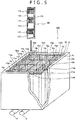
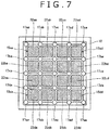
- the structure of a high-density cooling system according to the other embodiment of the present invention will be described with reference to FIG. 5 through FIG. 7 .
- the same portions as those in the cooling system shown in FIG. 1 and FIG. 4 will be given the same reference signs and will be omitted from being described in detail.
- a high-density cooling system that cools 16 units in total of electronic devices stored in respective storage sections of a cooling tank, each unit including a board 120 mounting a plurality of processor boards 110, 112. Incidentally, this is for the purpose of exemplification.
- the number of the processor boards and the kind of the processor (CPU or GPU) per board are discretionary, the number of units of the electronic devices in the high-density cooling system is also discretionary, and such number or kind does not limit the configuration of the electronic device in the present invention.
- a cooling system 500 has a cooling tank 12, and an open space 10a is defined by a bottom wall 12a and side walls 12b of the cooling tank 12.
- the open space 10a is divided equally into sixteen by the provision of inner partitioning walls 13a, 13b, 13c, 13d, 13e in a length direction and inner partitioning walls 14a, 14b, 14c, 14d, 14e in a width direction in the cooling tank 12, whereby sixteen arrayed storage sections 15aa, 15ab, 15ac, 15ad, 15ba, 15bb, 15bc, 15bd, 15ca, 15cb, 15cc, 15cd, 15da, 15db, 15dc, 15dd (hereafter, occasionally referred to as "storage sections 15aa to 15dd" collectively) are defined.
- a first cooling liquid 13 is contained up to a liquid level 19.
- the storage sections 15aa, 15ab, 15ac, 15ad, 15ba, 15bb, 15bc, 15bd, 15ca, 15cb, 15cc, 15cd, 15da, 15db, 15dc, 15dd are formed at bottom portions with inflow openings 16aa, 16ab, 16ac, 16ad, 16ba, 16bb, 16bc, 16bd, 16ca, 16cb, 16cc, 16cd, 16da, 16db, 16dc, 16dd (hereafter, occasionally referred to as "inflow openings 16aa to 16dd" collectively) for the first cooling liquid 13, respectively.
- the outflow openings are formed at positions where the plurality of inner partitioning walls defining respective storage sections intersect with one another, or in the vicinities of such positions.
- the storage section 15aa is defined by the inner partitioning wall 13a, 13b in the length direction and the inner partitioning wall 14a, 14b in the width direction, and the outflow openings 17aa, 17ba, 17ab, 17bb are formed to be located respectively at an intersection point of the inner partitioning wall 13a and the inner partitioning wall 14a, an intersection point of the inner partitioning wall 13a and the inner partitioning wall 14b, an intersection point of the inner partitioning wall 13b and the inner partitioning wall 14a, and an intersection point of the inner partitioning wall 13b and the inner partitioning wall 14b.
- the storage section 15bb is defined by the inner partitioning walls 13b, 13c in the length direction and the inner partitioning walls 14b, 14c in the width direction, and the outflow openings 17bb, 17cb, 17bc, 17cc are formed to be located respectively at an intersection point of the inner partitioning wall 13b and the inner partitioning wall 14b, an intersection point of the inner partitioning wall 13b and the inner partitioning wall 14c, an intersection point of the inner partitioning wall 13c and the inner partitioning wall 14b, and an intersection point of the inner partitioning wall 13c and the inner partitioning wall 14c.
- the outflow openings are formed at respective one ends of outflow pipes 170 piercing through the bottom wall 12a of the cooling tank 12 and extending to the vicinity of the liquid level 19.
- the outflow openings 17bb, 17cb, 17bc, 17cc are formed at respective one ends of the outflow pipes 170 which are defined by the inner partitioning walls 13b, 13c in the length direction and the inner partitioning walls 14b, 14c in the width direction and which are located respectively at an intersection point of the inner partitioning wall 13b and the inner partitioning wall 14b, an intersection point of the inner partitioning wall 13b and the inner partitioning wall 14c, an intersection point of the inner partitioning wall 13c and the inner partitioning wall 14b, and an intersection point of the inner partitioning wall 13c and the inner partitioning wall 14c.
- respective other ends of the outflow pipes are formed respectively with bottom openings 18aa, 18ab, 18ac, 18ad, 18ae, 18ba, 18bb, 18bc, 18bd, 18be, 18ca, 18cb, 18cc, 18cd, 18ce, 18da, 18db, 18dc, 18dd, 18de, 18ea, 18eb, 18ec, 18ed, 18ee (hereafter, occasionally referred to as "bottom openings 18aa to 18ee" collectively).
- the outflow openings are defined at the positions where the plurality of inner partitioning walls defining the respective storage sections intersect with one another, an advantage is obtained in that the outflow openings provided for the respective storage sections can be secured to be distributed to four corners of each storage section.
- the outflow pipes 170 arranged at the four corners of the section define the outflow openings 17bb, 17bc, 17cb and 17cc.
- the outflow openings are defined like this, one outflow opening can become an outflow opening common to the plurality of storage sections.
- the outflow opening 17bb is a part of the outflow openings for the storage section 15aa and at the same time, is also a part of the outflow openings for the storage sections 15ab, 15ba and 15bb.
- the positions and the number of the outflow pipes provided for each storage section are discretionary, and one or plural outflow pipes may, of course, be provided in the vicinities of the positions where the plurality of inner partitioning walls defining each storage section intersect with one another.
- the outflow pipes are not required to be integrated with the inner partitioning walls and may be pipes arranged apart from the inner partitioning walls.
- each outflow pipe 170 may be formed with one or more small holes 171 in the longitudinal direction of the outflow pipe 170. These small holes 171 accelerate the flow of the first cooling liquid 13 remaining in the midway of the storage section in the depth direction.
- each of the inflow openings 16aa to 16dd is not required to be a cylindrical opening, as illustrated.
- a header with a plurality of nozzles may be connected to one end of a cylinder to define the inflow opening by the plurality of nozzles.
- an electronic device 100 is stored and immersed in the first cooling liquid 13.
- the electronic device 100 is the same as the electronic device in the preceding one embodiment and will be omitted herein from being described in detail.
- the first cooling liquid 13 of the quantity sufficient to immerse the whole of the electronic device 100 is contained up to the liquid level 19.
- the first cooling liquid 13 is the same as the first cooling liquid in the preceding one embodiment and will be omitted herein from being described in detail.
- the cooling tank 12 is provided with an inlet 16 for distributing the first cooling liquid 13 through a distribution pipe (not shown) toward the inflow openings 16aa to 16dd provided at the respective storage sections 15aa to 15dd and an outlet 18 for collecting through a collecting pipe (not shown) the first cooling liquids 13 passing through the outflow openings 17aa to 17ee of the respective storage sections 15aa to 15dd.
- the first cooling liquid 13 cooled to a predetermined temperature continuously goes through the interiors of the respective storage sections 15aa to 15dd whereby the electronic devices 100 stored in the respective storage sections 15aa to 15dd can be kept at a predetermined temperature or lower during the operations
- a second flow passage that by a heat exchanger, cools the first cooling liquid 13 coming out of the outlet 18 of the cooling tank 12 to return the cooled cooling liquid to the inlet 16 of the cooling tank 12.
- Each of the distributed first heat exchangers 22aa to 22dd is immersed in the surface layer portion of the first cooling liquid 13 in each of the storage sections 15aa to 15dd.
- each of the distributed first heat exchangers 22aa to 22dd may be mechanically held by a top board (not show) .
- each of the distributed first heat exchangers 22aa to 22dd may be connected to a second heat exchanger disposed outside the cooling tank 12 through a first flow passage (not shown) .
- This connection may take any of a method of providing second heat exchangers of the same number as the distributed first heat exchangers 22aa to 22dd to make connections therebetween individually, a method of dividing the distributed first heat exchangers 22aa to 22dd into plural groups (e.g., four) each comprising a number (e.g. four) of heat exchangers and of providing second heat exchangers of the number corresponding to the groups to make connections therebetween individually, and a method of connecting one second heat exchanger to the whole of the distributed first heat exchangers 22aa to 22dd.
- the first cooling liquid 13 entering at the inlet 16 is distributed through a distribution pipe not shown toward the inflow openings 16aa to 16dd formed at the bottom portions of the storage sections 15aa to 15dd.
- the first cooling liquid 13 is forced upward from the inflow openings 16aa to 16dd and takes heat away directly or through the heat radiating members 114 from the processors and the peripheral electronic components (not shown) on the processor boards 110, 112 mounted on the board 120 of the electronic device 100 to cool the electronic device as a whole.
- the first cooling liquid 13 when forced upward from the inflow opening 16bb, goes up toward the liquid level 19 while taking heat away from the surfaces of the processors and the peripheral electronic components (not shown) on the processor boards 110, 112 and further, moves toward the outflow openings 17bb, 17bc, 17cb, 17cc.
- each volume of the storage sections 15aa to 15dd is small to be about 1/16 of the volume of the open space 10a of the cooling tank 12, and the electronic device 100 stored therein is also small to be about 1/4 wide of the width of the cooling tank 12.
- the cooling efficiency of the electronic device 100 by the first cooling liquid 13 is extremely excellent, and the first cooling fluid 13 can effectively be prevented from remaining around the electronic device 100.
- each of the distributed first heat exchangers 22aa to 22dd takes heat away from the surface layer portion of the first cooling liquid 13 to take the heat outside the cooling tank 12.
- a double cooling is performed which includes the liquid immerse cooling of the whole of the main heating elements and the peripheral electronic components (not shown) by the first cooling liquid 13 within the cooling tank 12 having the open space and the deprivation of heat from the surface layer portion of the liquid immerse refrigerant (the first cooling liquid 13) by the distributed first heat exchangers 22aa to 22dd.
- the first cooling liquid 13 goes through the outflow openings 17aa to 17ee located in the vicinity of the surface level 19 in the cooling tank 12, goes down the outflow pipes 170 to go through the bottom openings 18aa to 18ee, and is collected to the outlet 18 through the collecting pipe (not shown).
- the inflow opening may be formed at a lateral surface of each storage section.
- an electronic device of the width (for example, about 1/2, 1/3 or 1/4) being smaller than that in the prior art is stored in the storage section of the volume being about 1/4 or the volume being smaller than about 1/4 of the volume of the open space of the cooling tank (for example, about 1/9 (in the case of the division of 3 in length by 3 in width), 1/12 (in the case of the division of 3 in length by 4 in width), or 1/16 (in the case of the division of 4 in length by 4 in width) of the open space volume), and the cooling liquid is made to flow individually, so that it becomes possible to cool the plurality of electronic devices individually and efficiently.
- the warmed cooling liquid can be made to flow out also from center portions of the cooling tank, it can be avoided that the cooling liquid stays at around the center of the cooling tank to cause the cooling performance to differ in dependence on the storage positions of the electronic devices as is the case in the prior art wherein warmed cooling liquid is made to flow out from the lateral surface of the cooling tank. Accordingly, the cooling performance of the plurality of electronic devices can be improved and can be stabilized by being prevented from being varied in cooling performance. Further, since the electronic devices stored in the storage sections can be reduced in dimension, it is possible to improve the handling and maintainability of the electronic devices.
- the double cooling can be performed which includes the liquid immerse cooling of the whole of the main heating elements and the peripheral electronic components (not shown) by the first cooling liquid 13 within the cooling tank 12 having the open space and the deprivation of heat from the surface layer portion of the liquid immerse cooling refrigerant (the first cooling liquid 13) by the first heat exchanger 22 or the distributed first heat exchangers 22aa to 22dd.
- the cooling system according to the one embodiment may be altered to a configuration wherein like the cooling tank in the cooling system shown in the other embodiment, the open space is divided by the provision of a plurality of inner partitioning walls within the cooling tank to define a plurality of arrayed storage sections while inflow openings and outflow openings are omitted.
- the processor mounted on the board of the electronic device 100 may include either or both of CPU and GPU and further may include a high speed memory, a chip set, a network unit, a PCI express bus, a bus switching unit, an SSD, and power units (ac-dc converter, dc-dc voltage converter and the like).
- the electronic device 100 may be an electronic device like a server including a blade server, a router, a storage device such as an SSD or the like.
- the electronic device may, of course, be of a smaller width (for example, about 1/2, 1/3 or 1/4) than that of those conventional in the prior art.
- the present invention is widely applicable to cooling systems for cooling electronic devices efficiently.
Landscapes
- Engineering & Computer Science (AREA)
- Physics & Mathematics (AREA)
- General Engineering & Computer Science (AREA)
- Thermal Sciences (AREA)
- Microelectronics & Electronic Packaging (AREA)
- Theoretical Computer Science (AREA)
- Computer Hardware Design (AREA)
- Human Computer Interaction (AREA)
- General Physics & Mathematics (AREA)
- Life Sciences & Earth Sciences (AREA)
- Sustainable Development (AREA)
- Mechanical Engineering (AREA)
- Cooling Or The Like Of Electrical Apparatus (AREA)
- Cooling Or The Like Of Semiconductors Or Solid State Devices (AREA)
Applications Claiming Priority (1)
| Application Number | Priority Date | Filing Date | Title |
|---|---|---|---|
| PCT/JP2015/060032 WO2016157397A1 (ja) | 2015-03-30 | 2015-03-30 | 電子機器の冷却システム |
Publications (2)
| Publication Number | Publication Date |
|---|---|
| EP3279765A1 true EP3279765A1 (de) | 2018-02-07 |
| EP3279765A4 EP3279765A4 (de) | 2018-12-05 |
Family
ID=57005313
Family Applications (1)
| Application Number | Title | Priority Date | Filing Date |
|---|---|---|---|
| EP15887550.0A Withdrawn EP3279765A4 (de) | 2015-03-30 | 2015-03-30 | Kühlsystem für elektronische vorrichtung |
Country Status (4)
| Country | Link |
|---|---|
| US (1) | US20180070477A1 (de) |
| EP (1) | EP3279765A4 (de) |
| JP (1) | JPWO2016157397A1 (de) |
| WO (1) | WO2016157397A1 (de) |
Cited By (2)
| Publication number | Priority date | Publication date | Assignee | Title |
|---|---|---|---|---|
| WO2020047565A1 (de) * | 2018-09-04 | 2020-03-12 | Claus Hinterecker | Vorrichtung zur kühlung von hochleistungsrechnern - oder schaltungen mit temperaturregelung |
| CN112600110A (zh) * | 2020-12-30 | 2021-04-02 | 记忆(广州)数码科技有限公司 | 一种高低压密封配电柜 |
Families Citing this family (20)
| Publication number | Priority date | Publication date | Assignee | Title |
|---|---|---|---|---|
| US10512192B2 (en) * | 2015-08-28 | 2019-12-17 | Mark Miyoshi | Immersion cooling system with low fluid loss |
| JP6790855B2 (ja) * | 2017-01-18 | 2020-11-25 | 富士通株式会社 | 液浸冷却装置、液浸冷却システム及び電子装置の冷却方法 |
| JP6788551B2 (ja) * | 2017-06-21 | 2020-11-25 | 日本電信電話株式会社 | 冷却装置 |
| US10925180B2 (en) * | 2019-03-04 | 2021-02-16 | Baidu Usa Llc | IT container system design approach for fast deployment and high compatibility application scenarios |
| JP2020176804A (ja) | 2019-04-22 | 2020-10-29 | 富士通株式会社 | 液浸槽、及び電子機器 |
| CN112020265B (zh) * | 2019-05-31 | 2022-06-28 | 华为技术有限公司 | 一种散热装置及处理器 |
| CN112996337A (zh) * | 2019-12-12 | 2021-06-18 | 阿里巴巴集团控股有限公司 | 冷却设备和边缘计算系统 |
| CN113467585B (zh) * | 2020-03-15 | 2022-11-15 | 英业达科技有限公司 | 服务器冷却系统 |
| US12050061B2 (en) * | 2020-12-14 | 2024-07-30 | Aavid Thermalloy, Llc | Shrouded powder patch |
| CN112947630B (zh) * | 2021-03-19 | 2022-06-10 | 山东英信计算机技术有限公司 | 一种控温系统 |
| US11729950B2 (en) | 2021-04-01 | 2023-08-15 | Ovh | Immersion cooling system with dual dielectric cooling liquid circulation |
| US11924998B2 (en) * | 2021-04-01 | 2024-03-05 | Ovh | Hybrid immersion cooling system for rack-mounted electronic assemblies |
| EP4068930B1 (de) | 2021-04-01 | 2024-03-13 | Ovh | Racksystem zur aufnahme einer elektronischen vorrichtung |
| US12137536B2 (en) | 2021-04-01 | 2024-11-05 | Ovh | Systems and methods for autonomously activable redundant cooling of a heat generating component |
| EP4068928B1 (de) * | 2021-04-01 | 2024-01-31 | Ovh | Kühlvorrichtung |
| WO2022208404A1 (en) | 2021-04-01 | 2022-10-06 | Ovh | Scissor structure for cable/tube management of rack-mounted liquid-cooled electronic assemblies |
| CN113727582A (zh) * | 2021-08-20 | 2021-11-30 | 苏州浪潮智能科技有限公司 | 一种服务器机房及其无源浸没散热系统 |
| US20230247795A1 (en) | 2022-01-28 | 2023-08-03 | The Research Foundation For The State University Of New York | Regenerative preheater for phase change cooling applications |
| CN115038303B (zh) * | 2022-06-17 | 2025-03-18 | 北京有竹居网络技术有限公司 | 浸没式液冷装置及液冷系统 |
| WO2025213171A1 (en) * | 2024-04-05 | 2025-10-09 | MTS IP Holdings Ltd | Immersion tank for signal integrity measurements |
Family Cites Families (12)
| Publication number | Priority date | Publication date | Assignee | Title |
|---|---|---|---|---|
| US2643282A (en) * | 1949-04-13 | 1953-06-23 | Albert D Greene | Electronic equipment cooling means |
| US3406244A (en) * | 1966-06-07 | 1968-10-15 | Ibm | Multi-liquid heat transfer |
| US4590538A (en) * | 1982-11-18 | 1986-05-20 | Cray Research, Inc. | Immersion cooled high density electronic assembly |
| US4888663A (en) * | 1986-03-25 | 1989-12-19 | Hughes Aircraft Company | Cooling system for electronic assembly |
| JPH04207098A (ja) * | 1990-11-30 | 1992-07-29 | Fujitsu Ltd | プリント基板ユニットの冷却方法 |
| JP2000277961A (ja) * | 1999-03-26 | 2000-10-06 | Toyota Motor Corp | 発熱素子の冷却装置および発熱素子の冷却方法 |
| JP4324934B2 (ja) * | 2000-12-13 | 2009-09-02 | Smc株式会社 | 自動回収機構付き冷却液循環装置 |
| JP2002295983A (ja) * | 2001-03-28 | 2002-10-09 | Maruyasu Industries Co Ltd | 熱交換器および熱交換器の熱交換能力を高める方法 |
| JP2007109695A (ja) * | 2005-10-11 | 2007-04-26 | Sumitomo Precision Prod Co Ltd | 起動特性に優れる素子冷却器 |
| JP4679457B2 (ja) * | 2006-07-18 | 2011-04-27 | 株式会社東芝 | サブクール低温装置 |
| US10123463B2 (en) * | 2008-08-11 | 2018-11-06 | Green Revolution Cooling, Inc. | Liquid submerged, horizontal computer server rack and systems and method of cooling such a server rack |
| EP2959357A4 (de) * | 2013-02-22 | 2016-10-12 | Green Revolution Cooling Inc | Flüssigkeitsgekühltes modulares datenzentrum |
-
2015
- 2015-03-30 JP JP2017508912A patent/JPWO2016157397A1/ja active Pending
- 2015-03-30 US US15/563,461 patent/US20180070477A1/en not_active Abandoned
- 2015-03-30 EP EP15887550.0A patent/EP3279765A4/de not_active Withdrawn
- 2015-03-30 WO PCT/JP2015/060032 patent/WO2016157397A1/ja not_active Ceased
Cited By (4)
| Publication number | Priority date | Publication date | Assignee | Title |
|---|---|---|---|---|
| WO2020047565A1 (de) * | 2018-09-04 | 2020-03-12 | Claus Hinterecker | Vorrichtung zur kühlung von hochleistungsrechnern - oder schaltungen mit temperaturregelung |
| CN113170595A (zh) * | 2018-09-04 | 2021-07-23 | 克劳斯·辛特雷克 | 通过温度调控来冷却高性能计算机或电路的装置 |
| US11452234B2 (en) | 2018-09-04 | 2022-09-20 | Claus Hinterecker | Device for cooling high-performance computers or high-performance circuits, with temperature control |
| CN112600110A (zh) * | 2020-12-30 | 2021-04-02 | 记忆(广州)数码科技有限公司 | 一种高低压密封配电柜 |
Also Published As
| Publication number | Publication date |
|---|---|
| EP3279765A4 (de) | 2018-12-05 |
| JPWO2016157397A1 (ja) | 2018-01-25 |
| WO2016157397A1 (ja) | 2016-10-06 |
| US20180070477A1 (en) | 2018-03-08 |
Similar Documents
| Publication | Publication Date | Title |
|---|---|---|
| EP3279765A1 (de) | Kühlsystem für elektronische vorrichtung | |
| EP3279764A1 (de) | Kühlsystem für elektronische vorrichtung | |
| CN107924896B (zh) | 电子设备的冷却系统 | |
| EP3229103A1 (de) | Kühlvorrichtung für elektronische einrichtung | |
| EP3249496A1 (de) | Elektronisches instrument und kühlvorrichtung für elektronisches instrument | |
| US11006547B2 (en) | Solution for precision cooling and fluid management optimization in immersion cooling | |
| JP5853072B1 (ja) | 電子機器の冷却システム | |
| CN111654995B (zh) | 用于快速部署和高兼容性应用场景的it容器系统设计方案 | |
| US10912229B1 (en) | Cooling system for high density racks with multi-function heat exchangers | |
| JP2017050548A (ja) | 電子機器の冷却システム | |
| US20170332514A1 (en) | Cooling system and cooling method for electronic equipment | |
| US20110315344A1 (en) | Interleaved, immersion-cooling apparatus and method for an electronic subsystem of an electronics rack | |
| CN107209538B (zh) | 用于液体冷却的系统 | |
| US20240306345A1 (en) | Immersion cooling system implementing a first container and a second container |
Legal Events
| Date | Code | Title | Description |
|---|---|---|---|
| PUAI | Public reference made under article 153(3) epc to a published international application that has entered the european phase |
Free format text: ORIGINAL CODE: 0009012 |
|
| 17P | Request for examination filed |
Effective date: 20171004 |
|
| AK | Designated contracting states |
Kind code of ref document: A1 Designated state(s): AL AT BE BG CH CY CZ DE DK EE ES FI FR GB GR HR HU IE IS IT LI LT LU LV MC MK MT NL NO PL PT RO RS SE SI SK SM TR |
|
| AX | Request for extension of the european patent |
Extension state: BA ME |
|
| DAV | Request for validation of the european patent (deleted) | ||
| DAX | Request for extension of the european patent (deleted) | ||
| A4 | Supplementary search report drawn up and despatched |
Effective date: 20181026 |
|
| RIC1 | Information provided on ipc code assigned before grant |
Ipc: G06F 1/20 20060101AFI20181022BHEP Ipc: H05K 7/20 20060101ALI20181022BHEP Ipc: H01L 23/473 20060101ALI20181022BHEP |
|
| STAA | Information on the status of an ep patent application or granted ep patent |
Free format text: STATUS: THE APPLICATION IS DEEMED TO BE WITHDRAWN |
|
| 18D | Application deemed to be withdrawn |
Effective date: 20190524 |