WO2016157428A1 - Dispositif de mesure, procédé de mesure et programme - Google Patents
Dispositif de mesure, procédé de mesure et programme Download PDFInfo
- Publication number
- WO2016157428A1 WO2016157428A1 PCT/JP2015/060182 JP2015060182W WO2016157428A1 WO 2016157428 A1 WO2016157428 A1 WO 2016157428A1 JP 2015060182 W JP2015060182 W JP 2015060182W WO 2016157428 A1 WO2016157428 A1 WO 2016157428A1
- Authority
- WO
- WIPO (PCT)
- Prior art keywords
- measurement data
- dimensional measurement
- dimensional
- moving body
- current time
- Prior art date
- Legal status (The legal status is an assumption and is not a legal conclusion. Google has not performed a legal analysis and makes no representation as to the accuracy of the status listed.)
- Ceased
Links
Images




Classifications
-
- G—PHYSICS
- G01—MEASURING; TESTING
- G01B—MEASURING LENGTH, THICKNESS OR SIMILAR LINEAR DIMENSIONS; MEASURING ANGLES; MEASURING AREAS; MEASURING IRREGULARITIES OF SURFACES OR CONTOURS
- G01B11/00—Measuring arrangements characterised by the use of optical techniques
- G01B11/24—Measuring arrangements characterised by the use of optical techniques for measuring contours or curvatures
-
- G—PHYSICS
- G01—MEASURING; TESTING
- G01C—MEASURING DISTANCES, LEVELS OR BEARINGS; SURVEYING; NAVIGATION; GYROSCOPIC INSTRUMENTS; PHOTOGRAMMETRY OR VIDEOGRAMMETRY
- G01C15/00—Surveying instruments or accessories not provided for in groups G01C1/00 - G01C13/00
-
- G—PHYSICS
- G01—MEASURING; TESTING
- G01C—MEASURING DISTANCES, LEVELS OR BEARINGS; SURVEYING; NAVIGATION; GYROSCOPIC INSTRUMENTS; PHOTOGRAMMETRY OR VIDEOGRAMMETRY
- G01C21/00—Navigation; Navigational instruments not provided for in groups G01C1/00 - G01C19/00
- G01C21/26—Navigation; Navigational instruments not provided for in groups G01C1/00 - G01C19/00 specially adapted for navigation in a road network
Definitions
- the present invention relates to a technique for acquiring three-dimensional measurement data using a two-dimensional laser scanner mounted on a moving body.
- 3 3D laser scanners are still expensive and difficult to obtain, so it is difficult to mount them on ordinary vehicles.
- a relatively inexpensive and easily available 2D laser scanner is installed on the vehicle at an angle, and 2D point cloud data measured while traveling is based on the vehicle's position and orientation. There is a method of generating three-dimensional point cloud data by combining them.
- MMS Mobile Mapping System
- MMS Mobile Mapping System
- Patent Document 1 describes the technology related to MMS described above.
- all the measured data are accumulate
- Patent Document 1 When generating three-dimensional point cloud data in real time using a two-dimensional laser scanner, as shown in Patent Document 1, if all of the acquired point cloud data is accumulated, the amount of data becomes enormous. It is difficult to process in.
- An object of the present invention is to provide a measurement system that can generate three-dimensional point cloud data with high positional accuracy using a two-dimensional laser scanner.
- the invention according to claim 1 is a measuring device, a first acquisition unit that acquires the amount of movement of the moving body, and a two-dimensional front that is attached to the moving body and is based on the current position of the moving body A second conversion unit that acquires measurement data; a first conversion unit that converts the two-dimensional measurement data into three-dimensional measurement data based on an attachment position and an attachment angle of the second acquisition unit with respect to the moving body; A second conversion unit that converts the three-dimensional measurement data based on the time before the current time into converted three-dimensional measurement data based on the current time based on the movement amount acquired by the first acquisition unit 3D measurement data based on the current time generated by the first conversion unit and the converted 3D measurement data are combined, and the total 3D measurement corresponding to the current position and the current time of the mobile body A join to generate data Characterized in that it comprises a.
- a first acquisition unit that acquires a moving amount of a moving body
- a first acquisition unit that is attached to the moving body and acquires forward two-dimensional measurement data based on a current position of the moving body.
- a measurement method that is executed by a measurement device including two acquisition units, and converts the two-dimensional measurement data into three-dimensional measurement data based on an attachment position and an attachment angle of the second acquisition unit with respect to the moving body. Based on the first conversion step to be performed and the amount of movement acquired by the first acquisition step, the three-dimensional measurement data based on the time before a predetermined time from the current time is converted into the converted three-dimensional measurement based on the current time.
- a first acquisition unit that acquires a moving amount of a moving body
- a first acquisition unit that is attached to the moving body and acquires front two-dimensional measurement data based on a current position of the moving body.
- a computer program executed by a measuring device including two acquisition units and a computer, wherein the two-dimensional measurement data is converted into three-dimensional measurement data based on an attachment position and an attachment angle of the second acquisition unit with respect to the moving body.
- the three-dimensional measurement data based on a time that is a predetermined time before the current time is converted into a three-dimensional conversion based on the current time.
- a second conversion unit for converting to measurement data, three-dimensional measurement data based on the current time generated by the first conversion unit, and the converted three-dimensional measurement data are combined, and the current position of the mobile body and the current At time Coupling unit to generate a comprehensive three-dimensional measurement data for response, and characterized by causing the computer to function as a.
- the measuring method by an Example is typically shown.
- the sensor utilized for the measurement system of an Example is shown. It is a figure explaining the coordinate system of a vehicle and a sensor. It is a block diagram which shows the structure of a measurement system. It is a figure explaining 2D point group data and 3D point group data. It is a figure which shows the position and attitude
- the measuring method by a modification is typically shown.
- the measuring device includes: a first acquisition unit that acquires the amount of movement of the moving body; and two-dimensional measurement data that is attached to the moving body and is based on the current position of the moving body.
- a first conversion unit that converts the two-dimensional measurement data into three-dimensional measurement data based on the attachment position and the attachment angle of the second acquisition unit with respect to the moving body, and the first acquisition unit
- a second conversion unit that converts the three-dimensional measurement data based on a time before a predetermined time based on a movement amount acquired by the acquisition unit into converted three-dimensional measurement data based on the current time;
- the above measuring device is mounted on a vehicle or other moving body, and the amount of movement is acquired by the first acquisition unit.
- two-dimensional measurement data ahead of the moving body is acquired by the second acquisition unit.
- a 1st conversion part converts 2D measurement data into 3D measurement data based on the attachment position and attachment angle with respect to the moving body of a 2nd acquisition part.
- three-dimensional measurement data is generated by the movement of the moving body.
- the second conversion unit converts the three-dimensional measurement data based on a time before a predetermined time from the current time into converted three-dimensional measurement data based on the current time.
- converted three-dimensional measurement data based on the current time is obtained from the three-dimensional measurement data generated at the past time.
- the measurement apparatus can generate comprehensive three-dimensional measurement data based on the current time from the two-dimensional measurement data.
- One aspect of the measurement apparatus includes a deletion unit that deletes three-dimensional measurement data corresponding to a position behind the current position of the moving body from the converted three-dimensional measurement data generated by the second conversion unit. .
- the amount of data stored in the measurement apparatus can be reduced.
- the first acquisition unit acquires the movement amount by SLAM based on outputs of a speed sensor, an angular velocity sensor, and an environment measurement sensor mounted on the moving body.
- the amount of movement of the moving body can be acquired with high accuracy, so that three-dimensional measurement data with high positional accuracy can be generated.
- the coupling unit outputs the comprehensive three-dimensional measurement data to an object recognition unit that recognizes an object in front of the moving body. Thereby, the object in front of the moving body can be recognized.
- a first acquisition unit that acquires a moving amount of a moving body, and a first acquisition unit that is attached to the moving body and acquires front two-dimensional measurement data based on the current position of the moving body.
- the three-dimensional measurement data based on a time before a predetermined time from the current time is converted into converted three-dimensional measurement data based on the current time.
- the second conversion step to be converted, the three-dimensional measurement data based on the current time generated by the first conversion step, and the converted three-dimensional measurement data are combined into the current position and the current time of the moving body.
- Corresponding total And a binding step of generating three-dimensional measurement data According to this measurement method, comprehensive three-dimensional measurement data based on the current time can be generated from the two-dimensional measurement data.
- a first acquisition unit that acquires a moving amount of a moving body, and two-dimensional measurement data that is attached to the moving body and that is forward based on the current position of the moving body is acquired.
- a program executed by a measurement device including a second acquisition unit and a computer that performs the two-dimensional measurement data on the two-dimensional measurement data based on an attachment position and an attachment angle of the second acquisition unit with respect to the moving body.
- the three-dimensional measurement data Based on the movement amount acquired by the first conversion unit and the first acquisition unit, the three-dimensional measurement data based on a time that is a predetermined time before the current time is converted into a three-dimensional conversion based on the current time.
- a second conversion unit for converting to measurement data, three-dimensional measurement data based on the current time generated by the first conversion unit, and the converted three-dimensional measurement data are combined, and the current position of the mobile body and the current Times of Day Coupling unit to generate a corresponding overall three-dimensional measurement data, as to function the computer.
- This program can be stored and handled in a storage medium.
- FIG. 1 schematically shows a three-dimensional point cloud measurement method according to this embodiment.
- the two-dimensional laser scanner 5 is attached to the vehicle at an angle, and the two-dimensional point cloud data is synthesized by combining the two-dimensional point cloud data based on the position and orientation of the vehicle. Generate.
- the point cloud data behind the host vehicle is deleted, and only the point cloud data positioned in front of the host vehicle is retained, thereby generating local three-dimensional point group data based on the host vehicle position. Thereby, an increase in the amount of data can be suppressed, and accordingly, an increase in the amount of calculation in the three-dimensional point group processing such as object recognition can be suppressed.
- the relative movement amount of the vehicle is calculated with high accuracy by using SLAM (Simultaneous Localization and Mapping) technology for estimating the position and orientation of the vehicle.
- SLAM Simultaneous Localization and Mapping
- FIG. 2 shows a sensor used in the measurement system according to the embodiment.
- the measurement system is mounted on the vehicle 1 as a moving body.
- the vehicle 1 is equipped with a vehicle speed sensor 2, a gyro sensor 3, an environment measurement sensor 4, and a two-dimensional laser scanner 5 for measuring a three-dimensional point group.
- the vehicle speed sensor 2 detects the speed of the vehicle 1 by measuring a vehicle speed pulse composed of a pulse signal generated along with the rotation of the vehicle wheel.
- the gyro sensor 3 is an example of an angular velocity sensor, detects the angular velocity of the vehicle when the direction of the vehicle is changed, and outputs angular velocity data and relative azimuth data.
- the environmental measurement sensor 4 is used for self-position estimation, and a camera, a laser scanner, etc. can be used.
- a two-dimensional laser scanner separate from the two-dimensional laser scanner 5 is horizontally attached to the bumper portion of the vehicle 1 as the environmental measurement sensor 4.
- the two-dimensional laser scanner 5 is installed in the vehicle 1 at an angle rather than horizontal. In this embodiment, it is assumed that the two-dimensional laser scanner 5 is attached to the vehicle 1 at an elevation angle of 20 degrees with the front direction of the vehicle 1 as the front of the sensor.
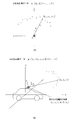
- FIG. 3A shows a vehicle coordinate system.
- the front direction of the vehicle 1 is the X axis
- the left direction is the Y axis
- the vertical direction is the Z axis
- the origin is the center of gravity of the vehicle.
- the X axis corresponds to the roll axis
- the amount of rotation around the X axis is indicated by “ ⁇ ”.
- the Y axis corresponds to the pitch axis, and the amount of rotation around the Y axis is indicated by “ ⁇ ”.
- the Z axis corresponds to the yaw axis, and the amount of rotation about the Z axis is indicated by “ ⁇ ”.
- ⁇ indicates an angle in the traveling direction of the vehicle 1.
- FIG. 3B shows a coordinate system of the two-dimensional laser scanner 5 (hereinafter referred to as “sensor coordinate system”).
- the scan plane is the X S Y S plane by the XS axis and the Y S axis
- the sensor front direction is the XS axis
- the left direction is the Y S axis
- the direction perpendicular to the scan plane Is the Z S axis.
- FIG. 4 is a block diagram illustrating a functional configuration of the measurement system.
- the measurement system includes a SLAM unit 11, a three-dimensional conversion unit 12, a coordinate conversion unit 13, a point group deletion unit 14, and a point group combination unit 15 in addition to the sensors shown in FIG. 2.
- the two-dimensional laser scanner 5 outputs the measurement data z t at the time t on the two-dimensional plane defined by the mounting angle with respect to the vehicle 1 to the three-dimensional conversion unit 12.
- the three-dimensional conversion unit 12 converts the measurement data z t acquired from the two-dimensional laser scanner 5 into three-dimensional point group data q t and outputs it to the point group coupling unit 15.
- FIG. 5A shows an example of two-dimensional point group data output from the two-dimensional laser scanner 5.
- the two-dimensional point group data is given as a set of the distance r and the scanning angle ⁇ from the two-dimensional laser scanner 5 to each measurement point on the scan plane. Therefore, the three-dimensional conversion unit 12 converts the two-dimensional point group data (r k , ⁇ k ) acquired from the two-dimensional laser scanner 5 into the sensor coordinate system (X S Y S Z S coordinate system) according to the following equation (1). ) At position (x S, k , y S, k , z S, k ).
- z S, k is the height of the scanning surface of the two-dimensional laser scanner 5, and is zero here because the reference of the two-dimensional laser scanner 5 is the scanning surface.
- FIG. 5B shows an example of three-dimensional point cloud data.
- the three-dimensional point group data is given as a set of coordinates (x, y, z) of each measurement point in the vehicle coordinate system (XYZ coordinate system) based on the position of the center of gravity of the vehicle 1. Therefore, the three-dimensional conversion unit 12 is based on the two-dimensional laser scanner mounting position and mounting angle (x ls , y ls , z ls , ⁇ ls , ⁇ ls , ⁇ ls ) shown in FIG.
- the coordinate (x S, k , y S, k , z S, k ) position in the sensor coordinate system (X S Y S Z S coordinate system) obtained by (1) is expressed by the coordinate (x k , Y k , z k ).
- the three-dimensional conversion unit 12 generates the three-dimensional conversion data q t by converting all measurement points constituting the measurement data z t in this way.
- the vehicle speed sensor 2 detects the speed v t of the vehicle 1 at time t and outputs it to the SLAM unit 11.
- the gyro sensor 3 detects the angular velocity ⁇ t at time t and outputs it to the SLAM unit 11.
- the environmental measurement sensor 4 outputs measurement data z t slam to the SLAM unit 11.
- the SLAM unit 11 uses the speed v t output from the vehicle speed sensor 2, the angular velocity ⁇ t output from the gyro sensor 3, and the measurement data z t slam output from the environment measurement sensor 4 to drive the vehicle by SLAM. 1 position and orientation are estimated.
- the SLAM unit 11 assumes that the vehicle 1 travels on a two-dimensional plane as shown in FIG. 6, and the position and posture (x v , y) of the vehicle 1 in the external coordinate system (X W Y W coordinate system). v , ⁇ v ) is estimated.
- the coordinate conversion unit 13 performs coordinate conversion of the three-dimensional point group P t-1 generated at the previous time (t ⁇ 1) based on the movement amount ( ⁇ x v , ⁇ y v , ⁇ v ), and the current time Conversion to a point group P ′ t ⁇ 1 based on the position of the center of gravity of the vehicle at t .
- the point group P t ⁇ 1 before conversion is expressed as
- the coordinate conversion unit 13 applies to each point p i included in the point group P t ⁇ 1 .
- a point group P ′ t ⁇ 1 shown in FIG. N is the number of measurement points per scan.
- the point group deletion unit 14 sets a point group behind the center of gravity of the vehicle 1, that is, a point group whose X coordinate is negative as a point group A. 'The point group obtained by removing from t-1 P' point cloud A point group P and 't-1.
- the point group combining unit 15 combines the point group P ′′ t ⁇ 1 and the point group q t as described below, so that the three-dimensional point group is based on the center of gravity position of the vehicle at the current time t. Data P t is generated.
- Figure 7 is a diagram schematically showing a three-dimensional point group data P t generated by the measurement system.
- the position of the vehicle 1 at the previous time (t ⁇ 1) is denoted by O t ⁇ 1
- the current position at the current time t is denoted by O t .
- the vehicle 1 has moved by a movement amount ( ⁇ x w , ⁇ y w , ⁇ w ) from the previous time (t ⁇ 1) to the current time t.
- the three-dimensional point group P t-1 generated at the previous time (t-1) is a point group A belonging to the rear area, that is, a point behind the current position of the vehicle 1 in the X-axis direction.
- Group point group with negative X coordinate
- the point group behind this is deleted by the point group deletion unit 14.
- the measurement data acquired the current time t by the two-dimensional laser scanner 5 is three-dimensional point cloud q t is converted by the three-dimensional conversion unit 12 into three-dimensional data.
- the point group combining unit 15 and the three-dimensional point group q t acquired at the current time t and the three-dimensional point group P t ⁇ 1 (that is, P ′′ t ⁇ 1 ) after the rear point group is deleted.
- the latest three-dimensional point cloud data P t is generated by combining t .
- Recently three-dimensional point group data P t thus obtained shows a 3D point group in front of the vehicle 1 (X-coordinate is positive).
- Measurement system during the movement of the vehicle 1 repeatedly executes the above processing continues to update the three-dimensional point group data P t. Thereby, the measurement system can always hold the three-dimensional point cloud data P t ahead of the current position of the vehicle 1.
- the three-dimensional point group data P t obtained in this way is sent to the object recognition unit is used, such as the recognition of the label.
- point cloud processing such as object recognition can be performed in real time even with limited memory and calculation resources of a general vehicle.
- the movement amount of the vehicle can be acquired with high accuracy by using the SLAM technology, highly accurate three-dimensional point cloud data can be generated.
- the point group deletion unit 14 deletes the backward point group data, that is, the point group data whose X coordinate is negative, based on the position of the vehicle 1 at the current time t.
- the point cloud deletion unit 14 may also delete the point cloud data above the vehicle 1. Specifically, as shown in FIG. 8, a plane PL extending obliquely forward from the current position of the vehicle 1 is defined, and the point group control unit 14 is positioned behind the plane PL (X coordinate is in a negative direction).
- the point cloud data to be deleted may be deleted. Thereby, the data amount of the point cloud data held in the measurement system can be further reduced.
- the reference position O of the vehicle 1 is the center of gravity of the vehicle 1, but the application of the present invention is not limited to this.
- the reference position O of the vehicle 1 may be set as a driver position, a mounting position of a two-dimensional laser scanner, or the like.
- the above embodiment is based on the premise that the vehicle 1 is traveling on a flat surface (flat road), but when the posture detection sensor for detecting the posture (roll, pitch, etc.) is mounted on the vehicle 1. is a 3D point group data P t which measurement system outputs by correcting the output of the attitude detection sensor, it is possible to improve the accuracy of the 3D point group data generated.
- the present invention can be used for a measuring device mounted on a vehicle.
Landscapes
- Engineering & Computer Science (AREA)
- Radar, Positioning & Navigation (AREA)
- Remote Sensing (AREA)
- Physics & Mathematics (AREA)
- General Physics & Mathematics (AREA)
- Automation & Control Theory (AREA)
- Length Measuring Devices By Optical Means (AREA)
Abstract
L'invention concerne un dispositif de mesure qui est installé dans un corps mobile tel qu'un véhicule et qui, au moyen d'une unité de type SLAM (microscope ultrasonique à balayage laser) permet d'acquérir des quantités de mouvement du corps mobile. De plus, des données de mesure à deux dimensions de la partie avant du corps mobile sont acquises par un scanner au laser à deux dimensions. Une unité de transformation à trois dimensions transforme des données de mesure à deux dimensions en données de mesure à trois dimensions, en fonction de l'emplacement de fixation et de l'angle de fixation du scanner au laser à deux dimensions par rapport au corps mobile. Une unité de transformation de coordonnées transforme des données de mesure en trois dimensions ayant en tant que repère un point dans le temps antérieur selon une durée de temps prescrite par rapport au point dans le temps en cours, en des données de mesure en trois dimensions transformées ayant le point dans le temps en cours comme repère. Les données de mesure en trois dimensions générées par l'unité de transformation en trois dimensions et ayant le point dans le temps en cours comme repère sont combinées avec les données de mesure en trois dimensions transformées pour générer des données de mesure en trois dimensions synthétisées qui correspondent à l'emplacement en cours du corps mobile et au point dans le temps en cours.
Priority Applications (1)
| Application Number | Priority Date | Filing Date | Title |
|---|---|---|---|
| PCT/JP2015/060182 WO2016157428A1 (fr) | 2015-03-31 | 2015-03-31 | Dispositif de mesure, procédé de mesure et programme |
Applications Claiming Priority (1)
| Application Number | Priority Date | Filing Date | Title |
|---|---|---|---|
| PCT/JP2015/060182 WO2016157428A1 (fr) | 2015-03-31 | 2015-03-31 | Dispositif de mesure, procédé de mesure et programme |
Publications (1)
| Publication Number | Publication Date |
|---|---|
| WO2016157428A1 true WO2016157428A1 (fr) | 2016-10-06 |
Family
ID=57004850
Family Applications (1)
| Application Number | Title | Priority Date | Filing Date |
|---|---|---|---|
| PCT/JP2015/060182 Ceased WO2016157428A1 (fr) | 2015-03-31 | 2015-03-31 | Dispositif de mesure, procédé de mesure et programme |
Country Status (1)
| Country | Link |
|---|---|
| WO (1) | WO2016157428A1 (fr) |
Cited By (9)
| Publication number | Priority date | Publication date | Assignee | Title |
|---|---|---|---|---|
| CN107179086A (zh) * | 2017-05-24 | 2017-09-19 | 北京数字绿土科技有限公司 | 一种基于激光雷达的制图方法、装置及系统 |
| CN108534789A (zh) * | 2017-12-27 | 2018-09-14 | 达闼科技(北京)有限公司 | 一种多路径定位坐标统一方法、电子设备和可读存储介质 |
| CN109115176A (zh) * | 2018-09-05 | 2019-01-01 | 上海华测导航技术股份有限公司 | 一种移动式的三维激光扫描系统 |
| WO2020071414A1 (fr) * | 2018-10-02 | 2020-04-09 | パナソニック インテレクチュアル プロパティ コーポレーション オブ アメリカ | Procédé de codage de données tridimensionnelles, procédé de décodage de données tridimensionnelles, dispositif de codage de données tridimensionnelles, et dispositif de décodage de données tridimensionnelles |
| WO2020071416A1 (fr) * | 2018-10-02 | 2020-04-09 | パナソニック インテレクチュアル プロパティ コーポレーション オブ アメリカ | Procédé et dispositif de codage de données tridimensionnelles, et procédé et dispositif de décodage de données tridimensionnelles |
| CN111367138A (zh) * | 2020-04-14 | 2020-07-03 | 长春理工大学 | 一种新型激光扫描投影装置 |
| US12411493B2 (en) | 2020-11-18 | 2025-09-09 | Kubota Corporation | Mobile machine, control unit, and method of controlling operation of a mobile machine |
| US12443198B2 (en) | 2020-11-18 | 2025-10-14 | Kubota Corporation | Mobile machine, data generation unit, and method of generating data |
| US12464964B2 (en) | 2020-11-18 | 2025-11-11 | Kubota Corporation | Mobile machine, control unit, data generation unit, method of controlling operation of a mobile machine, and method of generating data |
Citations (4)
| Publication number | Priority date | Publication date | Assignee | Title |
|---|---|---|---|---|
| JPS63186308A (ja) * | 1987-01-28 | 1988-08-01 | Hitachi Ltd | 移動体の誘導方法、および装置 |
| JP2012242967A (ja) * | 2011-05-17 | 2012-12-10 | Fujitsu Ltd | 地図処理方法及びプログラム、並びにロボットシステム |
| WO2014132509A1 (fr) * | 2013-02-27 | 2014-09-04 | シャープ株式会社 | Dispositif de reconnaissance d'environnement circonvoisin, système mobile autonome l'utilisant et procédé de reconnaissance d'environnement circonvoisin |
| JP2014202601A (ja) * | 2013-04-04 | 2014-10-27 | 株式会社Ihiエアロスペース | 植物位置計測装置と方法 |
-
2015
- 2015-03-31 WO PCT/JP2015/060182 patent/WO2016157428A1/fr not_active Ceased
Patent Citations (4)
| Publication number | Priority date | Publication date | Assignee | Title |
|---|---|---|---|---|
| JPS63186308A (ja) * | 1987-01-28 | 1988-08-01 | Hitachi Ltd | 移動体の誘導方法、および装置 |
| JP2012242967A (ja) * | 2011-05-17 | 2012-12-10 | Fujitsu Ltd | 地図処理方法及びプログラム、並びにロボットシステム |
| WO2014132509A1 (fr) * | 2013-02-27 | 2014-09-04 | シャープ株式会社 | Dispositif de reconnaissance d'environnement circonvoisin, système mobile autonome l'utilisant et procédé de reconnaissance d'environnement circonvoisin |
| JP2014202601A (ja) * | 2013-04-04 | 2014-10-27 | 株式会社Ihiエアロスペース | 植物位置計測装置と方法 |
Non-Patent Citations (1)
| Title |
|---|
| TAKUMI NAKAMOTO ET AL.: "3-D Map Generation in a Dynamic Environment by a Mobile Robot Equipped with Laser Range Finders", IEICE TECHNICAL REPORT, vol. 106, no. 114, 29 June 2006 (2006-06-29), pages 25 - 30 * |
Cited By (15)
| Publication number | Priority date | Publication date | Assignee | Title |
|---|---|---|---|---|
| CN107179086B (zh) * | 2017-05-24 | 2020-04-24 | 北京数字绿土科技有限公司 | 一种基于激光雷达的制图方法、装置及系统 |
| CN107179086A (zh) * | 2017-05-24 | 2017-09-19 | 北京数字绿土科技有限公司 | 一种基于激光雷达的制图方法、装置及系统 |
| CN108534789A (zh) * | 2017-12-27 | 2018-09-14 | 达闼科技(北京)有限公司 | 一种多路径定位坐标统一方法、电子设备和可读存储介质 |
| CN109115176A (zh) * | 2018-09-05 | 2019-01-01 | 上海华测导航技术股份有限公司 | 一种移动式的三维激光扫描系统 |
| CN109115176B (zh) * | 2018-09-05 | 2021-07-06 | 上海华测导航技术股份有限公司 | 一种移动式的三维激光扫描系统 |
| JP7358376B2 (ja) | 2018-10-02 | 2023-10-10 | パナソニック インテレクチュアル プロパティ コーポレーション オブ アメリカ | 三次元データ符号化方法、三次元データ復号方法、三次元データ符号化装置、及び三次元データ復号装置 |
| WO2020071416A1 (fr) * | 2018-10-02 | 2020-04-09 | パナソニック インテレクチュアル プロパティ コーポレーション オブ アメリカ | Procédé et dispositif de codage de données tridimensionnelles, et procédé et dispositif de décodage de données tridimensionnelles |
| JPWO2020071414A1 (ja) * | 2018-10-02 | 2021-09-02 | パナソニック インテレクチュアル プロパティ コーポレーション オブ アメリカPanasonic Intellectual Property Corporation of America | 三次元データ符号化方法、三次元データ復号方法、三次元データ符号化装置、及び三次元データ復号装置 |
| WO2020071414A1 (fr) * | 2018-10-02 | 2020-04-09 | パナソニック インテレクチュアル プロパティ コーポレーション オブ アメリカ | Procédé de codage de données tridimensionnelles, procédé de décodage de données tridimensionnelles, dispositif de codage de données tridimensionnelles, et dispositif de décodage de données tridimensionnelles |
| JP2023175879A (ja) * | 2018-10-02 | 2023-12-12 | パナソニック インテレクチュアル プロパティ コーポレーション オブ アメリカ | 三次元データ符号化方法、三次元データ復号方法、三次元データ符号化装置、及び三次元データ復号装置 |
| JP7612798B2 (ja) | 2018-10-02 | 2025-01-14 | パナソニック インテレクチュアル プロパティ コーポレーション オブ アメリカ | 三次元データ符号化方法、三次元データ復号方法、三次元データ符号化装置、及び三次元データ復号装置 |
| CN111367138A (zh) * | 2020-04-14 | 2020-07-03 | 长春理工大学 | 一种新型激光扫描投影装置 |
| US12411493B2 (en) | 2020-11-18 | 2025-09-09 | Kubota Corporation | Mobile machine, control unit, and method of controlling operation of a mobile machine |
| US12443198B2 (en) | 2020-11-18 | 2025-10-14 | Kubota Corporation | Mobile machine, data generation unit, and method of generating data |
| US12464964B2 (en) | 2020-11-18 | 2025-11-11 | Kubota Corporation | Mobile machine, control unit, data generation unit, method of controlling operation of a mobile machine, and method of generating data |
Similar Documents
| Publication | Publication Date | Title |
|---|---|---|
| WO2016157428A1 (fr) | Dispositif de mesure, procédé de mesure et programme | |
| JP7073315B2 (ja) | 乗物、乗物測位システム、及び乗物測位方法 | |
| EP3542182B1 (fr) | Procédés et systèmes de génération et de mise à jour de carte d'environnement de véhicule | |
| US11138465B2 (en) | Systems and methods for transforming coordinates between distorted and undistorted coordinate systems | |
| US9846043B2 (en) | Map creation apparatus, map creation method, and computer-readable recording medium | |
| CN112189225B (zh) | 车道线信息检测装置、方法以及存储被编程为执行该方法的计算机程序的计算机可读记录介质 | |
| CN106918830A (zh) | 一种基于多导航模块的定位方法及移动机器人 | |
| JP2022027593A (ja) | 可移動機器の測位方法、装置及び可移動機器 | |
| CN111912419A (zh) | 基于激光雷达的高精度语义导航地图构建方法和装置 | |
| CN110411457B (zh) | 基于行程感知与视觉融合的定位方法、系统、终端和存储介质 | |
| CN110345937A (zh) | 一种基于二维码的导航定姿定位方法和系统 | |
| KR102056147B1 (ko) | 자율주행차량을 위한 거리 데이터와 3차원 스캔 데이터의 정합 방법 및 그 장치 | |
| US11607999B2 (en) | Method and apparatus for invisible vehicle underbody view | |
| CN107615201A (zh) | 自身位置估计装置及自身位置估计方法 | |
| JP2016157197A (ja) | 自己位置推定装置、自己位置推定方法およびプログラム | |
| CN110458885B (zh) | 基于行程感知与视觉融合的定位系统和移动终端 | |
| US20220058817A1 (en) | System and method for generating a point cloud that includes surface normal information | |
| US11461944B2 (en) | Region clipping method and recording medium storing region clipping program | |
| US11238292B2 (en) | Systems and methods for determining the direction of an object in an image | |
| JP7227849B2 (ja) | 軌道生成装置 | |
| KR102916608B1 (ko) | 차량의 카메라 위치 정보 획득 장치 및 방법 | |
| US20240200953A1 (en) | Vision based cooperative vehicle localization system and method for gps-denied environments | |
| CN118196205A (zh) | 一种车载相机外参在线自标定方法及系统 | |
| CN114127658B (zh) | 使用道路模型2d流形的6d空间中的3d里程 | |
| US20220334259A1 (en) | Information processing apparatus, information processing method, and program |
Legal Events
| Date | Code | Title | Description |
|---|---|---|---|
| 121 | Ep: the epo has been informed by wipo that ep was designated in this application |
Ref document number: 15887581 Country of ref document: EP Kind code of ref document: A1 |
|
| NENP | Non-entry into the national phase |
Ref country code: DE |
|
| 122 | Ep: pct application non-entry in european phase |
Ref document number: 15887581 Country of ref document: EP Kind code of ref document: A1 |
|
| NENP | Non-entry into the national phase |
Ref country code: JP |