WO2016157538A1 - 冷凍サイクル装置 - Google Patents
冷凍サイクル装置 Download PDFInfo
- Publication number
- WO2016157538A1 WO2016157538A1 PCT/JP2015/060669 JP2015060669W WO2016157538A1 WO 2016157538 A1 WO2016157538 A1 WO 2016157538A1 JP 2015060669 W JP2015060669 W JP 2015060669W WO 2016157538 A1 WO2016157538 A1 WO 2016157538A1
- Authority
- WO
- WIPO (PCT)
- Prior art keywords
- refrigerant
- refrigeration cycle
- control unit
- value
- unit
- Prior art date
- Legal status (The legal status is an assumption and is not a legal conclusion. Google has not performed a legal analysis and makes no representation as to the accuracy of the status listed.)
- Ceased
Links
Images







Classifications
-
- F—MECHANICAL ENGINEERING; LIGHTING; HEATING; WEAPONS; BLASTING
- F25—REFRIGERATION OR COOLING; COMBINED HEATING AND REFRIGERATION SYSTEMS; HEAT PUMP SYSTEMS; MANUFACTURE OR STORAGE OF ICE; LIQUEFACTION SOLIDIFICATION OF GASES
- F25B—REFRIGERATION MACHINES, PLANTS OR SYSTEMS; COMBINED HEATING AND REFRIGERATION SYSTEMS; HEAT PUMP SYSTEMS
- F25B49/00—Arrangement or mounting of control or safety devices
- F25B49/02—Arrangement or mounting of control or safety devices for compression type machines, plants or systems
-
- F—MECHANICAL ENGINEERING; LIGHTING; HEATING; WEAPONS; BLASTING
- F24—HEATING; RANGES; VENTILATING
- F24F—AIR-CONDITIONING; AIR-HUMIDIFICATION; VENTILATION; USE OF AIR CURRENTS FOR SCREENING
- F24F11/00—Control or safety arrangements
- F24F11/30—Control or safety arrangements for purposes related to the operation of the system, e.g. for safety or monitoring
- F24F11/32—Responding to malfunctions or emergencies
- F24F11/36—Responding to malfunctions or emergencies to leakage of heat-exchange fluid
-
- F—MECHANICAL ENGINEERING; LIGHTING; HEATING; WEAPONS; BLASTING
- F24—HEATING; RANGES; VENTILATING
- F24F—AIR-CONDITIONING; AIR-HUMIDIFICATION; VENTILATION; USE OF AIR CURRENTS FOR SCREENING
- F24F11/00—Control or safety arrangements
- F24F11/70—Control systems characterised by their outputs; Constructional details thereof
- F24F11/72—Control systems characterised by their outputs; Constructional details thereof for controlling the supply of treated air, e.g. its pressure
- F24F11/74—Control systems characterised by their outputs; Constructional details thereof for controlling the supply of treated air, e.g. its pressure for controlling air flow rate or air velocity
- F24F11/77—Control systems characterised by their outputs; Constructional details thereof for controlling the supply of treated air, e.g. its pressure for controlling air flow rate or air velocity by controlling the speed of ventilators
-
- F—MECHANICAL ENGINEERING; LIGHTING; HEATING; WEAPONS; BLASTING
- F25—REFRIGERATION OR COOLING; COMBINED HEATING AND REFRIGERATION SYSTEMS; HEAT PUMP SYSTEMS; MANUFACTURE OR STORAGE OF ICE; LIQUEFACTION SOLIDIFICATION OF GASES
- F25B—REFRIGERATION MACHINES, PLANTS OR SYSTEMS; COMBINED HEATING AND REFRIGERATION SYSTEMS; HEAT PUMP SYSTEMS
- F25B13/00—Compression machines, plants or systems, with reversible cycle
-
- F—MECHANICAL ENGINEERING; LIGHTING; HEATING; WEAPONS; BLASTING
- F25—REFRIGERATION OR COOLING; COMBINED HEATING AND REFRIGERATION SYSTEMS; HEAT PUMP SYSTEMS; MANUFACTURE OR STORAGE OF ICE; LIQUEFACTION SOLIDIFICATION OF GASES
- F25B—REFRIGERATION MACHINES, PLANTS OR SYSTEMS; COMBINED HEATING AND REFRIGERATION SYSTEMS; HEAT PUMP SYSTEMS
- F25B49/00—Arrangement or mounting of control or safety devices
- F25B49/005—Arrangement or mounting of control or safety devices of safety devices
-
- F—MECHANICAL ENGINEERING; LIGHTING; HEATING; WEAPONS; BLASTING
- F25—REFRIGERATION OR COOLING; COMBINED HEATING AND REFRIGERATION SYSTEMS; HEAT PUMP SYSTEMS; MANUFACTURE OR STORAGE OF ICE; LIQUEFACTION SOLIDIFICATION OF GASES
- F25B—REFRIGERATION MACHINES, PLANTS OR SYSTEMS; COMBINED HEATING AND REFRIGERATION SYSTEMS; HEAT PUMP SYSTEMS
- F25B2313/00—Compression machines, plants or systems with reversible cycle not otherwise provided for
- F25B2313/027—Compression machines, plants or systems with reversible cycle not otherwise provided for characterised by the reversing means
-
- F—MECHANICAL ENGINEERING; LIGHTING; HEATING; WEAPONS; BLASTING
- F25—REFRIGERATION OR COOLING; COMBINED HEATING AND REFRIGERATION SYSTEMS; HEAT PUMP SYSTEMS; MANUFACTURE OR STORAGE OF ICE; LIQUEFACTION SOLIDIFICATION OF GASES
- F25B—REFRIGERATION MACHINES, PLANTS OR SYSTEMS; COMBINED HEATING AND REFRIGERATION SYSTEMS; HEAT PUMP SYSTEMS
- F25B2313/00—Compression machines, plants or systems with reversible cycle not otherwise provided for
- F25B2313/027—Compression machines, plants or systems with reversible cycle not otherwise provided for characterised by the reversing means
- F25B2313/02741—Compression machines, plants or systems with reversible cycle not otherwise provided for characterised by the reversing means using one four-way valve
-
- F—MECHANICAL ENGINEERING; LIGHTING; HEATING; WEAPONS; BLASTING
- F25—REFRIGERATION OR COOLING; COMBINED HEATING AND REFRIGERATION SYSTEMS; HEAT PUMP SYSTEMS; MANUFACTURE OR STORAGE OF ICE; LIQUEFACTION SOLIDIFICATION OF GASES
- F25B—REFRIGERATION MACHINES, PLANTS OR SYSTEMS; COMBINED HEATING AND REFRIGERATION SYSTEMS; HEAT PUMP SYSTEMS
- F25B2313/00—Compression machines, plants or systems with reversible cycle not otherwise provided for
- F25B2313/029—Control issues
- F25B2313/0293—Control issues related to the indoor fan, e.g. controlling speed
-
- F—MECHANICAL ENGINEERING; LIGHTING; HEATING; WEAPONS; BLASTING
- F25—REFRIGERATION OR COOLING; COMBINED HEATING AND REFRIGERATION SYSTEMS; HEAT PUMP SYSTEMS; MANUFACTURE OR STORAGE OF ICE; LIQUEFACTION SOLIDIFICATION OF GASES
- F25B—REFRIGERATION MACHINES, PLANTS OR SYSTEMS; COMBINED HEATING AND REFRIGERATION SYSTEMS; HEAT PUMP SYSTEMS
- F25B2500/00—Problems to be solved
- F25B2500/22—Preventing, detecting or repairing leaks of refrigeration fluids
- F25B2500/222—Detecting refrigerant leaks
-
- Y—GENERAL TAGGING OF NEW TECHNOLOGICAL DEVELOPMENTS; GENERAL TAGGING OF CROSS-SECTIONAL TECHNOLOGIES SPANNING OVER SEVERAL SECTIONS OF THE IPC; TECHNICAL SUBJECTS COVERED BY FORMER USPC CROSS-REFERENCE ART COLLECTIONS [XRACs] AND DIGESTS
- Y02—TECHNOLOGIES OR APPLICATIONS FOR MITIGATION OR ADAPTATION AGAINST CLIMATE CHANGE
- Y02B—CLIMATE CHANGE MITIGATION TECHNOLOGIES RELATED TO BUILDINGS, e.g. HOUSING, HOUSE APPLIANCES OR RELATED END-USER APPLICATIONS
- Y02B30/00—Energy efficient heating, ventilation or air conditioning [HVAC]
- Y02B30/70—Efficient control or regulation technologies, e.g. for control of refrigerant flow, motor or heating
Definitions
- the present invention relates to a refrigeration cycle apparatus having an indoor unit equipped with a blower fan.
- Patent Document 1 describes a refrigeration apparatus.
- This refrigeration apparatus includes a refrigerant detection unit that detects refrigerant leakage, and a control unit that drives a blower fan for a condenser or an evaporator when the refrigerant detection unit detects the refrigerant leakage.
- the refrigerant when the refrigerant leaks, the refrigerant is diffused or exhausted by the blower fan driven by the control unit, so that an increase in the refrigerant concentration at a predetermined location is prevented.
- the control unit stops driving the blower fan when the refrigerant is not detected by the refrigerant detection means due to the diffusion or exhaust of the refrigerant. Yes.
- the air blowing fan may be driven by a timer for a certain period of time regardless of the subsequent detection signal, or the operator turns off the switch to stop energization. It is described that the blower fan may be driven until.
- the control unit stops the blower fan when the refrigerant detection unit stops detecting the refrigerant and the detection signal stops, that is, when the concentration of the leaked refrigerant becomes zero. It has become. For this reason, since the ventilation fan continues to be driven unless the indoor refrigerant concentration becomes zero, unnecessary energy is consumed, and there is a problem that the user is required to pay an unnecessary electricity bill.
- the blower fan is driven for a certain time by a timer, or when the blower fan is driven until the worker turns off the switch to stop energization, the refrigerant leakage may continue even after the blower fan stops There is sex. For this reason, there existed a subject that the refrigerant
- the refrigerant detection means for example, a hot-wire semiconductor gas sensor
- the detection characteristics change.
- the refrigerant detection means since it is difficult to determine whether or not the hot-wire semiconductor gas sensor has been exposed to the refrigerant atmosphere, there is a problem that the refrigerant detection means whose detection characteristics have changed may be used continuously.
- the refrigerant detection means fails, there is a problem that the failed refrigerant detection means may continue to be used.
- the present invention has been made to solve at least one of the above-described problems, and even if the refrigerant leaks, the indoor refrigerant concentration can be prevented from increasing locally.
- the first object is to provide a refrigeration cycle apparatus capable of preventing consumption of unnecessary energy.
- the second object of the present invention is to provide a refrigeration cycle apparatus that can prevent the refrigerant detection means having changed detection characteristics from being used continuously.
- a third object of the present invention is to provide a refrigeration cycle apparatus that can prevent the failed refrigerant detection means from being used continuously.
- a refrigeration cycle apparatus includes a refrigeration cycle for circulating refrigerant, at least a load-side heat exchanger for the refrigeration cycle, an indoor unit installed indoors, and a control unit that controls the indoor unit;
- the indoor unit includes a blower fan and refrigerant detection means for detecting a concentration of the leaked refrigerant and outputting a detection signal to the control unit.
- the blower fan is operated when leakage of the refrigerant is detected, and the blower fan is stopped when the change in the concentration of the leaked refrigerant changes from positive to negative. .
- the refrigeration cycle apparatus includes a refrigeration cycle for circulating refrigerant, at least a load-side heat exchanger for the refrigeration cycle, an indoor unit installed indoors, and a control unit that controls the indoor unit.
- the indoor unit includes a blower fan and a refrigerant detection means that detects a concentration of the leaked refrigerant and outputs a detection signal to the control unit.
- the unit is configured to operate the blower fan when a refrigerant leak is detected and to stop the blower fan when a change in the concentration of the leaked refrigerant with time is negative.
- the refrigeration cycle apparatus includes a refrigeration cycle for circulating refrigerant, at least a load-side heat exchanger for the refrigeration cycle, an indoor unit installed indoors, and a control unit that controls the indoor unit.
- the indoor unit has a blower fan and a refrigerant detection means for detecting the refrigerant, and the control unit is connected to the refrigerant detection means in a non-detachable manner.
- a non-volatile memory provided in the control board, and the non-volatile memory can be set to a first value and a second value which are initial values.
- a leakage history bit is provided, and the leakage history bit can be rewritten only in one direction from the first value to the second value, and when the control unit detects leakage of the refrigerant , The leakage history bit to the first It rewrites the second value from, those which are configured to operate the blower fan.
- the refrigeration cycle apparatus includes a refrigeration cycle for circulating refrigerant, at least a load-side heat exchanger for the refrigeration cycle, an indoor unit installed indoors, and a control unit that controls the indoor unit.
- the indoor unit has a blower fan and a refrigerant detection means for detecting the refrigerant, and the control unit is connected to the refrigerant detection means in a non-detachable manner.
- a non-volatile memory provided in the control board, and the non-volatile memory can be set to a first value and a second value which are initial values.
- a failure bit is provided, and the failure bit is rewritable only in one direction from the first value to the second value, and the control unit, when the refrigerant detection means fails, The failure bit from the first value; Those that are configured to rewrite the serial second value.
- the blower fan can be stopped when the refrigerant leakage ends, unnecessary energy can be prevented from being consumed.
- the refrigerant detection means that is detachably connected is also replaced. It is possible to prevent the detection means from being used continuously.
- the refrigerant detection means that is detachably connected is also replaced. It is possible to prevent the means from being used continuously.
- FIG. 1 It is a figure which shows the example of the state which installed the indoor unit 1 of the refrigerating-cycle apparatus which concerns on Embodiment 1 of this invention in the indoor space 120.
- FIG. It is a graph which shows the example of the time change of a refrigerant
- FIG. 1 is a refrigerant circuit diagram showing a schematic configuration of a refrigeration cycle apparatus according to the present embodiment.
- a separate type air conditioner is illustrated as the refrigeration cycle apparatus.
- the dimensional relationship and shape of each component may differ from the actual ones.
- the air conditioner has a refrigeration cycle 40 for circulating a refrigerant.
- the refrigeration cycle 40 includes a compressor 3, a refrigerant flow switching device 4, a heat source side heat exchanger 5 (for example, an outdoor heat exchanger), a decompression device 6, and a load side heat exchanger 7 (for example, an indoor heat exchanger).
- the air conditioner includes, for example, an indoor unit 1 (an example of a load unit) installed indoors, and an outdoor unit 2 (an example of a heat source unit) installed outdoor, for example.
- the indoor unit 1 and the outdoor unit 2 are connected via extension pipes 10a and 10b that are part of the refrigerant pipe.
- a slightly flammable refrigerant such as HFO-1234yf or HFO-1234ze, or a strong flammable refrigerant such as R290 or R1270 is used.
- These refrigerants may be used as a single refrigerant, or may be used as a mixed refrigerant in which two or more kinds are mixed.
- a refrigerant having a flammability at or above a slight combustion level (for example, 2 L or more in the ASHRAE 34 classification) may be referred to as a “flammable refrigerant”.
- non-flammable refrigerants such as R22 and R410A having nonflammability (for example, 1 in the ASHRAE 34 classification) can be used.
- these refrigerants have a density higher than that of air at atmospheric pressure (for example, the temperature is room temperature (25 ° C.)).
- the compressor 3 is a fluid machine that compresses sucked low-pressure refrigerant and discharges it as high-pressure refrigerant.
- the refrigerant flow switching device 4 switches the flow direction of the refrigerant in the refrigeration cycle 40 between the cooling operation and the heating operation.
- a four-way valve is used as the refrigerant flow switching device 4.
- the heat source side heat exchanger 5 is a heat exchanger that functions as a radiator (for example, a condenser) during cooling operation and functions as an evaporator during heating operation. In the heat source side heat exchanger 5, heat exchange is performed between the refrigerant flowing through the inside and air (outside air) blown by an outdoor fan 5f described later.
- the decompression device 6 decompresses the high-pressure refrigerant into a low-pressure refrigerant.
- an electronic expansion valve whose opening degree can be adjusted is used.
- the load-side heat exchanger 7 is a heat exchanger that functions as an evaporator during cooling operation and functions as a radiator (for example, a condenser) during heating operation. In the load-side heat exchanger 7, heat exchange is performed between the refrigerant circulating in the interior and air blown by an indoor blower fan 7f described later.
- the cooling operation is an operation for supplying a low-temperature and low-pressure refrigerant to the load-side heat exchanger 7
- the heating operation is an operation for supplying a high-temperature and high-pressure refrigerant to the load-side heat exchanger 7. It is.
- a compressor 3, a refrigerant flow switching device 4, a heat source side heat exchanger 5 and a pressure reducing device 6 are accommodated.
- the outdoor unit 2 accommodates an outdoor blower fan 5 f that supplies outside air to the heat source side heat exchanger 5.
- the outdoor fan 5f is installed to face the heat source side heat exchanger 5. By rotating the outdoor fan 5f, an air flow passing through the heat source side heat exchanger 5 is generated.
- a propeller fan is used as the outdoor blower fan 5f.
- the outdoor fan 5f is arranged, for example, on the downstream side of the heat source side heat exchanger 5 in the air flow generated by the outdoor fan 5f.
- a refrigerant pipe connecting the extension pipe connection valve 13 a on the gas side (during cooling operation) and the refrigerant flow switching device 4, and a suction pipe 11 connected to the suction side of the compressor 3.
- a discharge pipe 12 connected to the discharge side of the compressor 3, a refrigerant pipe connecting the refrigerant flow switching device 4 and the heat source side heat exchanger 5, and a refrigerant pipe connecting the heat source side heat exchanger 5 and the decompression device 6.
- coolant piping which connects the decompression device 6 and the extension piping connection valve
- the extension pipe connection valve 13a is a two-way valve that can be switched between open and closed, and a flare joint is attached to one end thereof.
- the extension pipe connection valve 13b is composed of a three-way valve that can be switched between open and closed, and is a service that is used when evacuating one end of the valve (before the refrigerant is charged into the refrigeration cycle 40).
- a mouth 14a is attached, and a flare joint is attached to the other end.
- the high-temperature and high-pressure gas refrigerant compressed by the compressor 3 flows through the discharge pipe 12 during both the cooling operation and the heating operation.
- a low-temperature and low-pressure refrigerant gas refrigerant or two-phase refrigerant that has undergone an evaporating action flows through the suction pipe 11 in both the cooling operation and the heating operation.
- a service port 14b with a low-pressure side flare joint is connected to the suction pipe 11, and a service port 14c with a flare joint on the high-pressure side is connected to the discharge pipe 12.
- the service ports 14b and 14c are used for measuring an operating pressure by connecting a pressure gauge at the time of installation or repair of the air conditioner.
- the indoor unit 1 accommodates a load side heat exchanger 7. Further, the indoor unit 1 is provided with an indoor fan 7f that supplies air to the load-side heat exchanger 7. By rotating the indoor blower fan 7f, an air flow passing through the load-side heat exchanger 7 is generated.
- a centrifugal fan for example, a sirocco fan, a turbo fan, etc.
- a cross flow fan for example, a diagonal fan
- an axial fan for example, a propeller fan
- the indoor blower fan 7f of this example is disposed on the upstream side of the load side heat exchanger 7 in the air flow generated by the indoor blower fan 7f, but is disposed on the downstream side of the load side heat exchanger 7. Also good.
- a joint portion 15a for example, a flare joint for connecting the extension piping 10a is provided at a connection portion with the extension piping 10a on the gas side.
- a joint part 15b for example, a flare joint for connecting the extension pipe 10b is provided in the connection part with the liquid side extension pipe 10b. It has been.
- the indoor unit 1 includes the intake air temperature sensor 91 that detects the temperature of the indoor air sucked from the room, and the refrigerant temperature at the inlet portion during the cooling operation of the load side heat exchanger 7 (the outlet portion during the heating operation).
- a heat exchanger inlet temperature sensor 92 to detect, a heat exchanger temperature sensor 93 to detect the refrigerant temperature (evaporation temperature or condensation temperature) of the two-phase part of the load side heat exchanger 7 are provided.
- the indoor unit 1 is provided with a refrigerant detection means 99 described later. These sensors output a detection signal to the control unit 30 that controls the indoor unit 1 or the entire air conditioner.
- the control unit 30 has a microcomputer (hereinafter sometimes referred to as “microcomputer”) having a CPU, a ROM, a RAM, an I / O port, and the like.
- the control unit 30 can perform data communication with the operation unit 26 described later.
- the control unit 30 of this example controls the operation of the indoor unit 1 or the entire air conditioner including the operation of the indoor blower fan 7f based on the operation signal from the operation unit 26, the detection signal from the sensors, and the like.
- the control unit 30 may be provided in the housing of the indoor unit 1 or may be provided in the housing of the outdoor unit 2.
- the control part 30 may be comprised by the outdoor unit control part provided in the outdoor unit 2, and the indoor unit control part provided in the indoor unit 1 and capable of data communication with the outdoor unit control part.
- a solid line arrow indicates the flow direction of the refrigerant during the cooling operation.
- the refrigerant flow path switching device 4 switches the refrigerant flow path as indicated by a solid line, and the refrigerant circuit is configured so that the low-temperature and low-pressure refrigerant flows through the load-side heat exchanger 7.
- the high-temperature and high-pressure gas refrigerant discharged from the compressor 3 first flows into the heat source side heat exchanger 5 through the refrigerant flow switching device 4.
- the heat source side heat exchanger 5 functions as a condenser. That is, in the heat source side heat exchanger 5, heat exchange is performed between the refrigerant circulating inside and the air (outside air) blown by the outdoor blower fan 5f, and the heat of condensation of the refrigerant is radiated to the blown air. Thereby, the refrigerant flowing into the heat source side heat exchanger 5 is condensed and becomes a high-pressure liquid refrigerant.
- the high-pressure liquid refrigerant flows into the decompression device 6 and is decompressed to become a low-pressure two-phase refrigerant.
- the low-pressure two-phase refrigerant flows into the load side heat exchanger 7 of the indoor unit 1 via the extension pipe 10b.
- the load side heat exchanger 7 functions as an evaporator. That is, in the load-side heat exchanger 7, heat exchange is performed between the refrigerant circulating in the interior and the air (indoor air) blown by the indoor blower fan 7f, and the evaporation heat of the refrigerant is absorbed from the blown air.
- the refrigerant flowing into the load-side heat exchanger 7 evaporates to become a low-pressure gas refrigerant or a two-phase refrigerant. Further, the air blown by the indoor blower fan 7f is cooled by the endothermic action of the refrigerant.
- the low-pressure gas refrigerant or two-phase refrigerant evaporated in the load side heat exchanger 7 is sucked into the compressor 3 via the extension pipe 10 a and the refrigerant flow switching device 4.
- the refrigerant sucked into the compressor 3 is compressed into a high-temperature and high-pressure gas refrigerant. In the cooling operation, the above cycle is repeated.
- the refrigerant flow path switching device 4 switches the refrigerant flow path as indicated by the dotted line, and the refrigerant circuit is configured so that the high-temperature and high-pressure refrigerant flows through the load-side heat exchanger 7.
- the refrigerant flows in the opposite direction to that during the cooling operation, and the load side heat exchanger 7 functions as a condenser.
- FIG. 2 is a front view showing an external configuration of the indoor unit 1 of the air-conditioning apparatus according to the present embodiment.
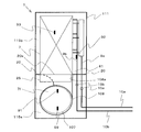
- FIG. 3 is a front view schematically showing the internal structure of the indoor unit 1 (with the front panel removed).
- FIG. 4 is a side view schematically showing the internal structure of the indoor unit 1. The left side in FIG. 4 shows the front side (indoor space side) of the indoor unit 1.
- the indoor unit 1 a floor-standing indoor unit 1 installed on the floor surface of the indoor space serving as the air-conditioning target space is illustrated.
- the positional relationship for example, vertical relationship etc.
- the indoor unit 1 includes a casing 111 having a vertically long rectangular parallelepiped shape.
- a suction port 112 for sucking air in the indoor space is formed in the lower front portion of the housing 111.
- the suction port 112 of this example is provided below the center portion in the vertical direction of the casing 111 and at a position near the floor surface.
- the air sucked from the suction port 112 is blown out into the room.
- An outlet 113 is formed.
- An operation unit 26 is provided on the front surface of the casing 111 above the suction port 112 and below the air outlet 113.
- the operation unit 26 is connected to the control unit 30 via a communication line, and data communication with the control unit 30 is possible.
- the operation start operation, the operation end operation, the operation mode switching, the set temperature, the set air volume, and the like of the indoor unit 1 (air conditioner) are performed by a user operation.
- the operation unit 26 may be provided with a display unit, an audio output unit, and the like that notify the user of information.
- the housing 111 is a hollow box, and a front opening is formed on the front surface of the housing 111.
- the casing 111 includes a first front panel 114a, a second front panel 114b, and a third front panel 114c that are detachably attached to the front opening.
- the first front panel 114a, the second front panel 114b, and the third front panel 114c all have a substantially rectangular flat plate-like outer shape.
- the first front panel 114a is detachably attached to the lower portion of the front opening of the casing 111.
- the suction port 112 is formed in the first front panel 114a.
- the second front panel 114b is disposed adjacent to and above the first front panel 114a, and is detachably attached to the central portion of the front opening of the housing 111 in the vertical direction.
- the operation unit 26 is provided on the second front panel 114b.
- the third front panel 114c is disposed adjacent to and above the second front panel 114b, and is detachably attached to the upper portion of the front opening of the housing 111.
- the above-described air outlet 113 is formed in the third front panel 114c.
- the internal space of the housing 111 is roughly divided into a space 115a serving as a blower section and a space 115b positioned above the space 115a and serving as a heat exchange section.
- the space 115a and the space 115b are partitioned by the partition portion 20.
- the partition part 20 has a flat plate shape, for example, and is arranged substantially horizontally.
- the partition portion 20 is formed with at least an air passage opening 20a serving as an air passage between the space 115a and the space 115b.
- the space 115a is exposed to the front side by removing the first front panel 114a from the housing 111, and the space 115b is obtained by removing the second front panel 114b and the third front panel 114c from the housing 111. Is exposed on the front side.
- the height at which the partition portion 20 is installed substantially matches the height of the upper end of the first front panel 114a (or the lower end of the second front panel 114b).
- the partition portion 20 may be formed integrally with a fan casing 108 described later, or may be formed integrally with a drain pan described later, or as a separate body from the fan casing 108 and the drain pan. It may be formed.
- an indoor blower fan 7f that generates an air flow from the inlet 112 toward the outlet 113 is disposed.
- the indoor blower fan 7f of this example is a sirocco fan that includes a motor (not shown) and an impeller 107 that is connected to an output shaft of the motor and has a plurality of blades arranged at equal intervals in the circumferential direction.
- the rotating shaft of the impeller 107 (motor output shaft) is arranged so as to be substantially parallel to the depth direction of the casing 111.
- the impeller 107 of the indoor blower fan 7 f is covered with a spiral fan casing 108.
- the fan casing 108 is formed separately from the casing 111, for example.
- a suction opening 108b for sucking room air through the suction port 112 is formed.
- the suction opening 108 b is disposed so as to face the suction port 112.
- a blowout opening 108a for blowing out the blown air is formed.
- the blowout opening 108 a is disposed so as to face upward, and is connected to the space 115 b through the air passage opening 20 a of the partition part 20.
- the outlet opening 108a communicates with the space 115b via the air passage opening 20a.
- the opening end of the outlet opening 108a and the opening end of the air passage opening 20a may be directly connected or indirectly connected via a duct member or the like.
- an electrical component box 25 in which a microcomputer constituting the control unit 30 and the like, various electrical components, a substrate and the like are accommodated is provided.
- the load side heat exchanger 7 is arranged in the air passage 81 in the space 115b.
- a drain pan (not shown) that receives condensed water condensed on the surface of the load side heat exchanger 7 is provided below the load side heat exchanger 7.
- the drain pan may be formed as a part of the partition part 20, or may be formed separately from the partition part 20 and disposed on the partition part 20.
- a refrigerant detection means 99 is provided at a position near the lower side in the vicinity of the suction opening 108b.
- the refrigerant detection means 99 for example, a gas sensor such as a semiconductor gas sensor or a hot wire semiconductor gas sensor is used.
- the refrigerant detection unit 99 detects, for example, the refrigerant concentration in the air around the refrigerant detection unit 99 and outputs a detection signal to the control unit 30. In the control unit 30, the presence or absence of refrigerant leakage is determined based on the detection signal from the refrigerant detection means 99.
- the refrigerant detection means 99 of the present embodiment is provided in a position lower in the casing 111 than the load-side heat exchanger 7 and the joint portions 15a and 15b. Thereby, at least when the indoor blower fan 7f is stopped, the refrigerant detection means 99 can reliably detect the leaked refrigerant.
- the refrigerant detection means 99 is provided at a position closer to the lower side of the suction opening 108b, but the installation position of the refrigerant detection means 99 may be another position.
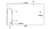
- FIG. 5 is a diagram illustrating an example of a state where the indoor unit 1 is installed in the indoor space 120.
- the refrigerant is intentionally leaked from the indoor unit 1 in the stopped state, and the measurement point A inside the indoor unit 1 and in the vicinity of the installation position of the refrigerant detection means 99 and the indoor unit 1
- the refrigerant concentration was measured at a measurement point B that is also away from the floor.
- FIG. 6 is a graph showing an example of a change over time in the refrigerant concentration when the refrigerant is leaked from the indoor unit 1.
- the horizontal axis of the graph represents time, and the vertical axis represents the refrigerant concentration.
- the solid line shows the change over time in the refrigerant concentration at the measurement point A, and the broken line shows the change over time in the refrigerant concentration at the measurement point B.
- FIG. 6 when refrigerant leakage starts in the indoor unit 1 at time T ⁇ b> 0, first, the refrigerant concentration at the measurement point A inside the indoor unit 1 increases.
- the refrigerant concentration at the measurement point A (more precisely, the refrigerant concentration detected by the refrigerant detection means 99) reaches a preset threshold value (time T1 in FIG. 6), as will be described later, The operation of the blower fan 7f is started. As a result, the air in the indoor space 120 is agitated and the refrigerant diffuses, so that the refrigerant concentration at the measurement point A temporarily decreases (time T1 to T2). However, since the leakage of the refrigerant in the indoor unit 1 continues, the refrigerant concentration at the measurement point A starts to increase again after time T2.
- the refrigerant concentration at the measurement point B which is away from the indoor unit 1 and the floor surface, hardly changes immediately after the start of refrigerant leakage.
- the refrigerant concentration at the measurement point B rapidly increases when the operation of the indoor blower fan 7f is started (time T1 to T2), and after a certain time has elapsed from the start of operation of the indoor blower fan 7f, the refrigerant at the measurement point A It almost coincides with the concentration (time T2). That is, the refrigerant leaked from the indoor unit 1 is uniformly diffused throughout the indoor space 120 due to the stirring effect by the operation of the indoor blower fan 7f.
- the refrigerant concentration after time T2 increases while maintaining a substantially uniform state in the entire indoor space 120.
- the refrigerant leakage ends (time T3).
- the increase in the refrigerant concentration stops.
- the refrigerant in the indoor space 120 leaks out of the room due to natural ventilation through the upper and lower gaps of the door.
- the refrigerant concentration in the entire indoor space 120 gradually decreases regardless of the operation and stop of the indoor blower fan 7f (after time T3). That is, after the refrigerant leakage is finished, the refrigerant concentration can be gradually lowered even if the indoor blower fan 7f is stopped. Therefore, in the present embodiment, the indoor blower fan 7f is stopped when the refrigerant leakage ends. Thereby, it is possible to prevent unnecessary energy from being consumed.
- the time change from positive to negative includes not only the case where the time change directly changes from positive to negative, but also the case where the time change changes from positive to negative through zero.
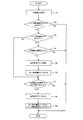
- FIG. 7 is a flowchart showing an example of the flow of the refrigerant leakage detection process (the operation and stop process of the indoor fan 7f) executed by the control unit 30.
- the refrigerant leakage detection process of FIG. 7 is repeatedly executed at predetermined time intervals at all times including during operation and stop of the air conditioner or only when the air conditioner is stopped.
- FIG. 8 is a state transition diagram illustrating an example of state transition of the air conditioner.
- the air conditioner in the initial state is in a normal state (no leakage state in FIG. 8) in which no refrigerant leaks.
- two flag areas of “fan forced operation flag” and “fan forced operation stop flag” are set in the RAM of the control unit 30. In the initial state, both the fan forced operation flag and the fan forced operation stop flag are set to off.
- a normal driving operation and a stopping operation are performed based on a user operation by the operation unit 26 (including a remote controller).
- control unit 30 acquires information on the refrigerant concentration around the refrigerant detection means 99 based on the detection signal from the refrigerant detection means 99.
- step S2 it is determined whether or not the fan forced operation stop flag in the RAM is set to OFF.
- the process proceeds to step S3, and when the fan forced operation stop flag is set to ON, the process ends.
- step S3 it is determined whether or not the fan forced operation flag in the RAM is set to OFF. If the fan forced operation flag is set to OFF, the process proceeds to step S4. If the fan forced operation flag is set to ON, the process proceeds to step S7.
- step S4 it is determined whether or not the refrigerant concentration detected by the refrigerant detection means 99 is equal to or greater than a preset threshold value. If it is determined that the refrigerant concentration is greater than or equal to the threshold value, the process proceeds to step S5, and if it is determined that the refrigerant concentration is less than the threshold value, the process ends.
- step S5 the operation of the indoor fan 7f is started (corresponding to time T1 in FIG. 6). When the indoor fan 7f is already in operation, the operation is continued as it is.
- the display unit liquid crystal screen or LED or the like
- a sound output unit, or the like is used to notify the user that the refrigerant has leaked and repaired by a professional service person. You may make it prompt.
- step S6 the fan forced operation flag is set to ON.
- the state of the air conditioner is set to the first abnormal state (leak state 1 in FIG. 8 (refrigerant leaking)). Then, it progresses to step S7.
- step S7 it is determined whether or not the change in the refrigerant concentration with time detected by the refrigerant detector 99 has changed from positive to negative.
- the process proceeds to step S8, and in other cases, the process ends.
- the refrigerant concentration detected by the refrigerant detection means 99 may temporarily decrease immediately after the activation of the indoor fan 7f (time T1 to T2), the indoor fan 7f Until a predetermined time elapses from the activation of, the process may be terminated without performing the determination in step S7.
- step S8 the indoor blower fan 7f is stopped (corresponding to time T3 in FIG. 6).
- the refrigerant concentration in the indoor space 120 is an allowable value (for example, the lower combustion limit concentration LFL or oxygen deficiency).
- an allowable value for example, the lower combustion limit concentration LFL or oxygen deficiency.
- a step of determining whether or not the refrigerant concentration is less than the allowable value may be further added after the Yes determination in step S7.
- step S8 the process proceeds to step S8 to stop the indoor blower fan 7f, and if it is determined that the refrigerant concentration is equal to or higher than the allowable value, processing is performed. Exit. Thereby, since the driving
- step S9 the fan forced operation flag is set to OFF and the fan forced operation stop flag is set to ON.
- the state of the air conditioner is set to the second abnormal state (leak state 2 (refrigerant leakage stop) in FIG. 8).
- the indoor fan 7f is operated. Be started. For this reason, the leaked refrigerant can be diffused indoors. Further, the operation of the indoor blower fan 7f is continued until the refrigerant leakage ends. Therefore, even if the refrigerant leaks, it can be suppressed that the refrigerant concentration is locally increased indoors.
- the indoor blower fan 7f can be stopped when the refrigerant leakage ends. Therefore, it is possible to prevent unnecessary energy from being consumed. Moreover, it is possible to prevent the user from having unnecessary uneasiness by continuing to operate the indoor fan 7f. After the refrigerant leakage ends, the indoor refrigerant concentration usually decreases gradually and does not increase again. For this reason, it can also be suppressed that the refrigerant concentration increases locally in the room after the indoor blower fan 7f is stopped.
- both the fan forced operation flag and the fan forced operation stop flag are set to OFF. Absent. Therefore, as shown in FIG. 8, once the state of the air conditioner is set to the leaked state 1 or the leaked state 2, the service person repairs the air conditioner, and then the service person clears the abnormality. Unless the fan forced operation stop flag is set to OFF, it does not return to the state without leakage.
- the method for canceling the abnormality is limited to a method that can be performed only by a professional service person. Thereby, since it can prevent that a user cancels
- the method for canceling the abnormality is limited to the following (1) to (4), for example.
- the refrigeration cycle apparatus includes the refrigeration cycle 40 that circulates the refrigerant, and the indoor unit 1 that houses at least the load-side heat exchanger 7 of the refrigeration cycle 40 and is installed indoors.
- the refrigeration cycle apparatus having the control unit 30 that controls the indoor unit 1, wherein the indoor unit 1 detects the indoor blower fan 7 f and the concentration of the leaked refrigerant and outputs a detection signal to the control unit 30.
- the refrigerant detecting means 99 is provided, and the control unit 30 operates the indoor blower fan 7f when detecting the leakage of the refrigerant, and triggers that the time change of the concentration of the leaked refrigerant has changed from positive to negative.
- the indoor fan 7f is configured to be stopped.
- the indoor ventilation fan 7f can be stopped when the refrigerant
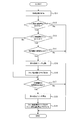
- FIG. 9 is a flowchart illustrating an example of the flow of the refrigerant leakage detection process executed by the control unit 30 of the air conditioner.
- the refrigerant leakage detection process of FIG. 9 is repeatedly executed at predetermined time intervals at all times including during operation and stop of the air conditioner or only when the air conditioner is stopped. Steps S11 to S16, S18 and S19 in FIG. 9 are the same as steps S1 to S6, S8 and S9 in FIG. 7, respectively.
- step S17 of FIG. 9 it is determined whether or not the change in the refrigerant concentration with time detected by the refrigerant detector 99 is negative (that is, whether or not the refrigerant concentration is decreasing).
- the process proceeds to step S18, and in other cases, the process ends. Note that, similarly to step S7 in FIG. 7, the process may be terminated without performing the determination in step S17 until a predetermined time has elapsed since the activation of the indoor fan 7f.
- the refrigeration cycle apparatus includes the refrigeration cycle 40 that circulates the refrigerant, and the indoor unit 1 that houses at least the load-side heat exchanger 7 of the refrigeration cycle 40 and is installed indoors.
- the refrigeration cycle apparatus having the control unit 30 that controls the indoor unit 1, wherein the indoor unit 1 detects the indoor blower fan 7 f and the concentration of the leaked refrigerant and outputs a detection signal to the control unit 30.
- Refrigerant control means 99, and the control unit 30 operates the indoor blower fan 7f when detecting leakage of the refrigerant, and the indoor blower fan 7f when the time change of the concentration of the leaked refrigerant is negative. Is configured to stop.
- the indoor ventilation fan 7f can be stopped when the refrigerant
- FIG. 10 is a graph showing an example of the change over time in the refrigerant concentration when the refrigerant is leaked from the indoor unit 1, and corresponds to FIG.
- the horizontal axis of the graph represents time, and the vertical axis represents the refrigerant concentration.
- the solid line shows the change over time in the refrigerant concentration at the measurement point A, and the broken line shows the change over time in the refrigerant concentration at the measurement point B.
- the forced operation of the indoor fan 7f is started, and the display unit, the audio output unit, and the like are notified to the user that the refrigerant leakage has occurred. If the forced operation of the indoor blower fan 7f or the notification of refrigerant leakage is suddenly executed, a user who is indoors may be surprised and go out of the room.
- the change in the refrigerant concentration over time is not only the timing at which the refrigerant leakage ends (time T5), but also the timing at which the operation of the indoor fan 7f is started (time T1), and the door opens during the refrigerant leakage. Also at the given timing (time T3), it changes from positive to negative.
- the time change of the refrigerant concentration becomes negative not only in the period after time T5 when the refrigerant leakage ends, but also in the period from time T1 to T2 and the period from time T3 to T4. Therefore, when the indoor blower fan 7f is stopped when the change in the refrigerant concentration with time is negative (for example, the second embodiment), the indoor blower fan 7f may be stopped before the refrigerant leakage ends. .
- the stopped indoor ventilation fan 7f when the time change of a refrigerant
- the time change changes from negative to positive includes not only the case where the time change directly changes from negative to positive but also the case where the time change changes positive from negative to zero.
- concentration is positive, you may make it operate the stopped indoor ventilation fan 7f again.
- FIG. 11 is a flowchart showing an example of the flow of the refrigerant leakage detection process executed by the control unit 30.
- the refrigerant leakage detection process in FIG. 11 is repeatedly executed at predetermined time intervals at all times including during operation and stop of the air conditioner or only when the air conditioner is stopped.
- Steps S21 to S25 and S27 to S29 in FIG. 11 are the same as steps S1 to S5 and S7 to S9 in FIG. 7, respectively.
- FIG. 12 is a state transition diagram illustrating an example of state transition of the air conditioner.
- step S30 in FIG. 11 in a state where the fan forced operation stop flag is set to ON (No in step S22 in FIG. 11; leakage state 2 in FIG. 12), has the refrigerant concentration changed over time from negative to positive? It is determined whether or not (step S30 in FIG. 11). If it is determined in step S30 that the change in the refrigerant concentration with time has changed from negative to positive, the process proceeds to step S25, and the operation of the stopped indoor fan 7f is resumed. Thereafter, in step S26, the fan forced operation stop flag is set to OFF, and the fan forced operation flag is set to ON. When the fan forced operation flag is set to ON, the state of the air conditioner transitions from the leakage state 2 in FIG. 12 to the leakage state 1. On the other hand, if it is determined in step S30 that the change in the refrigerant concentration with time remains negative or zero, the process ends.
- control unit 30 causes the stopped indoor fan 7f to be triggered by the change in the leaked refrigerant concentration over time from negative to positive. You may be comprised so that it may drive
- control unit 30 is configured to cause the stopped indoor blower fan 7f to operate again when the time change in the concentration of the leaked refrigerant is positive. Also good.
- the stopped indoor blower fan 7f can be operated again.
- Embodiment 4 FIG. Next, a refrigeration cycle apparatus according to Embodiment 4 of the present invention will be described. Note that the configuration of the refrigeration cycle apparatus according to the present embodiment is the same as that of the first embodiment, and a description thereof will be omitted.
- the indoor blower fan 7f when the indoor blower fan 7f is stopped when the change in the refrigerant concentration with time changes from positive to negative (for example, Embodiment 1), or when the change in the refrigerant concentration with time is negative.
- the indoor blower fan 7f is stopped (for example, Embodiment 2), the indoor blower fan 7f may be stopped before the refrigerant leakage ends.
- the threshold time is set to a time (several seconds to several minutes) longer than the period of time T3 to T4 in FIG.
- FIG. 13 is a flowchart showing an example of the flow of the refrigerant leakage detection process executed by the control unit 30.
- the refrigerant leakage detection process of FIG. 13 is repeatedly executed at predetermined time intervals at all times including during operation and stop of the air conditioner or only when the air conditioner is stopped.
- Steps S31 to S37, S39 and S40 in FIG. 13 are the same as steps S1 to S9 in FIG.
- FIG. 14 is a state transition diagram illustrating an example of state transition of the air conditioner.
- step S38 when the fan forced operation flag is set to ON (step S37 in FIG. 13; leakage state 1 in FIG. 14), the change in the refrigerant concentration with time changes from positive to negative (step Further, it is determined whether or not the decrease in the refrigerant concentration has continued for a threshold time or more (step S38). If it is determined in step S38 that the decrease in the refrigerant concentration has continued for the threshold time or longer, the process proceeds to step S39, and the indoor blower fan 7f is stopped. Thereafter, in step S40, the fan forced operation flag is set to OFF, and the fan forced operation stop flag is set to ON. By setting the fan forced operation stop flag to ON, the state of the air conditioner is set to the leakage present state 2 in FIG. On the other hand, when it is determined in step S38 that the refrigerant concentration decrease time has not been continued for the threshold time or longer, the process is terminated.
- control unit 30 causes the indoor state when the state in which the time change in the concentration of the leaked refrigerant is negative continues for a preset threshold time or longer.
- the blower fan 7f is configured to be stopped.
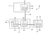
- FIG. 15 is a block diagram illustrating a configuration of the control unit 30 of the separate type air conditioner.
- the control unit 30 includes an indoor unit control unit 31 that is mounted on the indoor unit 1 and controls the indoor unit 1, and an outdoor unit control unit 32 that is mounted on the outdoor unit 2 and controls the outdoor unit 2. And a remote controller control unit 33 that is mounted on the remote controller 27 (or the operation unit 26) and controls the remote controller 27.
- the indoor unit control unit 31 includes a control board 31a and a control board 31b that can communicate with the control board 31a via a control line.
- the indoor unit control unit 31 can communicate with the outdoor unit control unit 32 and the remote control unit 33.
- a microcomputer 34 is mounted on the control board 31a.
- the control board 31b is mounted with a microcomputer 35 and a refrigerant detection means 99 (for example, a hot-wire semiconductor gas sensor) in a non-detachable manner.
- a refrigerant detection means 99 for example, a hot-wire semiconductor gas sensor
- the refrigerant detection means 99 may be provided at a position away from the control board 31b, and the wiring from the refrigerant detection means 99 may be connected to the control board 31b by soldering or the like.
- the control board 31b is provided separately from the control board 31a.
- the control board 31b may be omitted, and the refrigerant detection means 99 may be detachably connected to the control board 31a.
- the outdoor unit controller 32 has a control board 32a.
- a microcomputer 36 is mounted on the control board 32a.
- the remote controller 33 has a control board 33a.
- a microcomputer 37 is mounted on the control board 33a.
- the indoor unit control unit 31 and the outdoor unit control unit 32 are communicably connected via a control line 38.
- the indoor unit control unit 31 and the remote control unit 33 are communicably connected via a control line 39.
- the microcomputer 35 mounted on the control board 31b has a rewritable nonvolatile memory (for example, a flash memory).
- This nonvolatile memory is provided with a leakage history bit for storing a history of refrigerant leakage.
- the leakage history bit of the microcomputer 35 can be set to “0” or “1”.
- the initial value of this leakage history bit is “0”. In other words, in the case of the microcomputer 35 in a new state or the microcomputer 35 without a refrigerant leakage history, the leakage history bit is set to “0”.
- the leakage history bit of the microcomputer 35 is detected when the refrigerant detection means 99 detects the leakage of the refrigerant having a predetermined concentration (for example, a concentration of 1 ⁇ 4 of the lower combustion limit concentration LFL, a threshold value at which the indoor blower fan 7f starts operating). , “0” is rewritten to “1”. The leakage history bit of the microcomputer 35 can be irreversibly rewritten only in one direction from “0” to “1”. Further, the leakage history bit of the microcomputer 35 is maintained regardless of whether power is supplied to the microcomputer 35.
- the leakage history bit of the present embodiment is provided corresponding to the fan forced operation flag or the fan forced operation stop flag of the first to fourth embodiments.
- the memory (nonvolatile memory or volatile memory) of the microcomputers 34, 36, and 37 is provided with a leakage history bit corresponding to the leakage history bit of the microcomputer 35, respectively.
- the leakage history bits of the microcomputers 34, 36, and 37 can be set to “0” or “1”.
- the leakage history bits of the microcomputers 34, 36, and 37 can be rewritten bidirectionally between “0” and “1”.
- the value of the leakage history bit of the microcomputers 34, 36, and 37 is set to the same value as the leakage history bit of the microcomputer 35 acquired by communication.
- the leakage history bits of the microcomputers 34, 36, and 37 are set to the same value as the leakage history bits of the microcomputer 35 again when the power supply is resumed even if the power supply is interrupted and returns to the initial value (for example, “0”). Is set.
- the indoor unit control unit 31 When the leakage history bit of the microcomputer 34 is set to “0”, the indoor unit control unit 31 performs normal control of the indoor unit 1. The indoor unit 1 in this state performs a normal driving operation and a stopping operation based on the operation of the remote controller 27 or the like. On the other hand, when the leakage history bit of the microcomputer 34 is set to “1”, the indoor unit control unit 31 performs control to forcibly operate the indoor blower fan 7f.
- the outdoor unit control unit 32 When the leakage history bit of the microcomputer 36 is set to “0”, the outdoor unit control unit 32 performs normal control of the outdoor unit 2. On the other hand, when the leakage history bit of the microcomputer 36 is set to “1”, the outdoor unit control unit 32 performs control to stop the compressor 3. The stop of the compressor 3 is continued as long as the leakage history bit of the microcomputer 36 is continuously set to “1”.
- the remote controller control unit 33 When the leakage history bit of the microcomputer 37 is set to “0”, the remote controller control unit 33 performs normal control of the remote controller 27. On the other hand, when the leakage history bit of the microcomputer 37 is set to “1”, the remote controller control unit 33 displays, for example, information including an abnormality type or a treatment method on the display unit provided in the remote controller 27 (for example, “refrigerant leakage” Display a message such as “Contact Serviceman”, error code, etc.). This display is continued as long as the leakage history bit of the microcomputer 37 continues to be set to “1”.
- the microcomputer 35 irreversibly rewrites the leakage history bit from the initial value “0” to “1”.
- the leakage history bit of the microcomputer 35 is set to “1”
- the leakage history bits of the microcomputers 34, 36, and 37 are also rewritten from “0” to “1”.
- the service person who received the notification from the user replaces the control board 31b with a new one when repairing the refrigerant leakage point. This is because the leakage history bit of the microcomputers 34, 36, and 37 is maintained at “1” only by repairing the refrigerant leakage portion, and thus the normal operation of the air conditioner cannot be performed. Since the refrigerant detection means 99 is detachably connected to the control board 31b, the refrigerant detection means 99 is also exchanged when the control board 31b is exchanged.
- the leakage history bit of the microcomputer 35 mounted on the replaced control board 31b is set to “0” which is an initial value. Therefore, the leakage history bits of the microcomputers 34, 36, and 37 are also rewritten from “1” to “0”. Thereby, normal operation
- the refrigeration cycle apparatus includes the refrigeration cycle 40 that circulates the refrigerant, and the indoor unit 1 that houses at least the load-side heat exchanger 7 of the refrigeration cycle 40 and is installed indoors.
- the outdoor unit 2 that houses at least the heat source side heat exchanger 5 of the refrigeration cycle 40, the indoor unit control unit 31 that controls the indoor unit 1, and the indoor unit control unit 31 are communicably connected to control the outdoor unit 2.
- the indoor unit 1 includes an indoor blower fan 7f and a refrigerant detection means 99 that detects the refrigerant
- the indoor unit control unit 31 includes: A control board (in this example, the control board 31b) to which the refrigerant detection means 99 is detachably connected, and a non-volatile memory (in this example, a non-volatile memory provided in the microcomputer 35) provided in the control board; , Have The non-volatile memory is provided with leak history bits that can be set to initial values “0” and “1”. The leak history bits are changed from “0” to “1”.
- the indoor unit control unit 31 can be rewritten only in one direction, and is configured to rewrite the leakage history bit from “0” to “1” and to operate the indoor blower fan 7f when refrigerant leakage is detected. It is what has been. Further, the outdoor unit control unit 32 may be configured to stop the compressor 3 when the leakage history bit is rewritten from “0” to “1”.
- the refrigerant leakage history is irreversibly written in the nonvolatile memory of the control board 31b.
- the control board 31b In order to reset the leakage history of the refrigerant, it is necessary to replace the control board 31b with another control board 31b having no leakage history.
- the refrigerant detection means 99 that is detachably connected is also replaced. Therefore, it is possible to prevent the refrigerant detecting means 99 that has been exposed to the refrigerant atmosphere and whose detection characteristics have changed from being used continuously. Further, in this configuration, since the operation of the air conditioner cannot be resumed unless the control board 31b is replaced, the operation of the air conditioner that has not been repaired at the refrigerant leakage point is resumed due to human error or intentionally. Can be prevented.
- FIG. 6 A refrigeration cycle apparatus according to Embodiment 6 of the present invention will be described with reference to FIG.
- the refrigerant detection means 99 A failure bit for storing a failure history (for example, whether there is a failure) is provided.
- the failure bit can be set to “0” or “1” similarly to the leakage history bit, and its initial value is “0”. That is, in the case of the microcomputer 35 in a new state or the microcomputer 35 having no failure history of the refrigerant detection means 99, the failure bit is set to “0”.
- the failure bit of the microcomputer 35 is rewritten from “0” to “1”.
- the failure bit of the microcomputer 35 can be irreversibly rewritten only in one direction from “0” to “1”, similarly to the leakage history bit.
- the failure bit of the microcomputer 35 is maintained regardless of whether or not power is supplied to the microcomputer 35.
- the memory (nonvolatile memory or volatile memory) of the microcomputers 34, 36, and 37 is provided with a failure bit corresponding to the failure bit of the microcomputer 35, respectively.
- the failure bits of the microcomputers 34, 36, and 37 can be set to “0” or “1”.
- the failure bits of the microcomputers 34, 36, and 37 can be rewritten bidirectionally between “0” and “1”.
- the value of the failure bit of the microcomputers 34, 36, and 37 is set to the same value as the failure bit of the microcomputer 35 acquired by communication.
- the failure bits of the microcomputers 34, 36, and 37 are set to the same values as the failure bits of the microcomputer 35 again when the power supply is resumed even if the power supply is cut off and returned to the initial value (eg, “0”).
- the indoor unit control unit 31, the outdoor unit control unit 32, and the remote control unit 33 are the indoor unit 1, the outdoor unit 2, and the remote control 27, respectively. Perform normal control.
- the outdoor unit control unit 32 and the remote control unit 33 perform forced stop of the compressor 3 (operation not permitted) and information to the display unit of the remote control 27, respectively. Control display.
- the indoor unit control unit 31 may control the forced operation of the indoor fan 7f.
- the refrigeration cycle apparatus includes the refrigeration cycle 40 that circulates the refrigerant, and the indoor unit 1 that houses at least the load-side heat exchanger 7 of the refrigeration cycle 40 and is installed indoors.
- a refrigeration cycle apparatus having a control unit 30 (for example, an indoor unit control unit 31) that controls the indoor unit 1, wherein the indoor unit 1 includes an indoor blower fan 7f and a refrigerant detection means 99 that detects the refrigerant.
- the control unit 30 includes a control board (in this example, the control board 31b) to which the refrigerant detection means 99 is detachably connected, and a non-volatile memory (in this example, provided in the control board).
- the failure history of the refrigerant detection means 99 is irreversibly written in the nonvolatile memory of the control board 31b.
- the control board 31b In order to reset the failure history of the refrigerant detection means 99, it is necessary to replace the control board 31b with another control board 31b.
- the refrigerant detection means 99 that is detachably connected is also replaced. Therefore, it is possible to prevent the failed refrigerant detection means 99 from being used continuously.
- the operation of the air conditioner cannot be resumed unless the control board 31b is replaced, the operation of the air conditioner in a state where the refrigerant detection means 99 remains broken will be resumed due to human error or intentionally. Can be prevented. For this reason, the safety
- Embodiment 7 FIG. Next, a refrigeration cycle apparatus according to Embodiment 7 of the present invention will be described.
- a heat pump water heater is illustrated as the refrigeration cycle apparatus.
- the configuration of the refrigeration cycle apparatus according to the present embodiment will be described. Note that the flow of processing executed by the control unit in the present embodiment is the same as that in the first embodiment (or any one of the second to sixth embodiments), and a description thereof will be omitted.
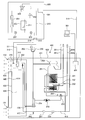
- FIG. 16 is a refrigerant circuit diagram showing a schematic configuration of the refrigeration cycle apparatus according to the present embodiment.
- the heat pump water heater includes a refrigerant circuit 310 that circulates a refrigerant to form a refrigeration cycle, and a water circuit 410 (an example of a heat medium circuit) that distributes water (an example of a heat medium).
- the refrigerant circuit 310 includes a compressor 203, a refrigerant flow switching device 204, a load-side heat exchanger 202, a first decompression device 206, an intermediate pressure receiver 205, a second decompression device 207, and a heat source-side heat exchanger 201.
- the heat pump water heater has a load unit 400 (indoor unit) installed indoors, and a heat source unit 300 (outdoor unit) installed outdoor, for example.
- the load unit 400 is installed, for example, in a storage space such as a storage room inside a building in addition to a kitchen, a bathroom, and a laundry room.
- the above-described flammable refrigerant or non-flammable refrigerant is used as the refrigerant circulating in the refrigerant circuit 310.
- Compressor 203 is a fluid machine that compresses sucked low-pressure refrigerant and discharges it as high-pressure refrigerant.
- the compressor 203 of this example includes an inverter device and the like, and can change the capacity (the amount of refrigerant sent out per unit time) by arbitrarily changing the drive frequency.
- the refrigerant flow switching device 204 switches the flow direction of the refrigerant in the refrigerant circuit 310 between the normal operation and the defrosting operation.
- a four-way valve is used as the refrigerant flow switching device 204.
- the load-side heat exchanger 202 is a refrigerant-water heat exchanger that performs heat exchange between the refrigerant flowing through the refrigerant circuit 310 and the water flowing through the water circuit 410.
- a plate heat exchanger (brazing plate heat exchanger) having a configuration in which a plurality of members are joined by brazing is used.
- the load-side heat exchanger 202 functions as a condenser (heat radiator) that heats water during normal operation, and functions as an evaporator (heat absorber) during defrosting operation.
- the first decompression device 206 and the second decompression device 207 adjust the flow rate of the refrigerant and perform pressure adjustment (decompression) of the refrigerant flowing into the load side heat exchanger 202 or the heat source side heat exchanger 201.
- the intermediate pressure receiver 205 is located between the first decompression device 206 and the second decompression device 207 in the refrigerant circuit 310 and accumulates excess refrigerant.
- a suction pipe 211 connected to the suction side of the compressor 203 passes through the intermediate pressure receiver 205. In the intermediate pressure receiver 205, heat exchange between the refrigerant flowing through the suction pipe 211 and the refrigerant in the intermediate pressure receiver 205 is performed.
- the intermediate pressure receiver 205 has a function as an internal heat exchanger in the refrigerant circuit 310.
- the first pressure reducing device 206 and the second pressure reducing device 207 for example, electronic expansion valves that can change the opening degree under the control of the control unit 301 described later are used.
- the heat source side heat exchanger 201 is a refrigerant-air heat exchanger that performs heat exchange between the refrigerant flowing through the refrigerant circuit 310 and air (outside air) blown by an outdoor fan (not shown).
- the heat source side heat exchanger 201 functions as an evaporator (heat absorber) during normal operation, and functions as a condenser (heat radiator) during defrosting operation.
- the compressor 203, the refrigerant flow switching device 204, the first pressure reducing device 206, the intermediate pressure receiver 205, the second pressure reducing device 207, and the heat source side heat exchanger 201 are accommodated in the heat source unit 300.
- the load side heat exchanger 202 is accommodated in the load unit 400.
- the heat source unit 300 and the load unit 400 are connected by, for example, two extension pipes 311 and 312 that are part of the refrigerant pipe.
- the extension pipes 311 and 312 and the refrigerant pipe in the heat source unit 300 are connected via joint parts 313 and 314 (for example, flare joints), respectively.
- joint portions 315 and 316 are interposed. Are connected to each other.
- the heat source unit 300 is mainly operated by the refrigerant circuit 310 (for example, the compressor 203, the refrigerant flow switching device 204, the first decompression device 206, the second decompression device 207, an outdoor fan not shown).
- a control unit 301 for controlling is provided.
- the control unit 301 has a microcomputer provided with a CPU, ROM, RAM, I / O port, and the like.
- the control unit 301 can perform data communication with a control unit 401 and an operation unit 501 described later via a control line 510.
- the refrigerant circuit 310 Next, an example of the operation of the refrigerant circuit 310 will be described.
- the direction of refrigerant flow during normal operation in the refrigerant circuit 310 is indicated by solid arrows.
- the refrigerant flow switching device 204 switches the refrigerant flow path as indicated by a solid line, and the refrigerant circuit 310 is configured such that high-temperature and high-pressure refrigerant flows through the load-side heat exchanger 202.
- the load side heat exchanger 202 functions as a condenser. That is, in the load side heat exchanger 202, heat exchange between the refrigerant flowing through the refrigerant flow path and the water flowing through the water flow path of the load side heat exchanger 202 is performed, and the heat of condensation of the refrigerant is radiated to the water. Thereby, the refrigerant that has flowed into the load-side heat exchanger 202 condenses into a high-pressure liquid refrigerant. Moreover, the water which flows through the water flow path of the load side heat exchanger 202 is heated by the heat radiation from the refrigerant.
- the high-pressure liquid refrigerant condensed in the load-side heat exchanger 202 flows into the first decompression device 206 via the extension pipe 312 and is slightly decompressed to become a two-phase refrigerant.
- the two-phase refrigerant flows into the intermediate pressure receiver 205 and is cooled by heat exchange with the low-pressure gas refrigerant flowing through the suction pipe 211 to become a liquid refrigerant.
- This liquid refrigerant flows into the second decompression device 207 and is decompressed to become a low-pressure two-phase refrigerant.
- the low-pressure two-phase refrigerant flows into the heat source side heat exchanger 201. During normal operation, the heat source side heat exchanger 201 functions as an evaporator.
- the heat source side heat exchanger 201 heat exchange is performed between the refrigerant circulating in the interior and the air (outside air) blown by the outdoor blower fan, and the evaporation heat of the refrigerant is absorbed from the blown air.
- the refrigerant flowing into the heat source side heat exchanger 201 evaporates to become a low-pressure gas refrigerant.
- the low-pressure gas refrigerant flows into the suction pipe 211 via the refrigerant flow switching device 204.
- the low-pressure gas refrigerant that has flowed into the suction pipe 211 is heated by heat exchange with the refrigerant in the intermediate-pressure receiver 205 and is sucked into the compressor 203.
- the refrigerant sucked into the compressor 203 is compressed into a high-temperature and high-pressure gas refrigerant. In normal operation, the above cycle is repeated.
- the flow direction of the refrigerant during the defrosting operation in the refrigerant circuit 310 is indicated by a broken line arrow.
- the refrigerant flow path switching device 204 switches the refrigerant flow path as indicated by broken lines, and the refrigerant circuit 310 is configured so that the high-temperature and high-pressure refrigerant flows through the heat source side heat exchanger 201.
- the heat source side heat exchanger 201 functions as a condenser. That is, in the heat source side heat exchanger 201, heat exchange is performed between the refrigerant flowing through the inside and the frost adhering to the surface of the heat source side heat exchanger 201. Thereby, the frost adhering to the surface of the heat source side heat exchanger 201 is heated and melted by the heat of condensation of the refrigerant.
- a hot water storage tank 251 a hot water storage tank 251, a load side heat exchanger 202, a pump 253, a booster heater 254, a three-way valve 255, a strainer 256, a flow switch 257, a pressure relief valve 258, an air vent valve 259, and the like are connected via a water pipe. It has the structure which was made.
- a drain outlet 262 for draining the water in the water circuit 410 is provided in the middle of the piping constituting the water circuit 410.
- the hot water storage tank 251 is a device that accumulates water inside.
- the hot water storage tank 251 contains a coil 261 connected to the water circuit 410.
- the coil 261 heats the water accumulated in the hot water storage tank 251 by exchanging heat between the water (hot water) circulating in the water circuit 410 and the water stored in the hot water storage tank 251.
- the hot water storage tank 251 has a built-in water heater 260.
- the submerged heater 260 is a heating means for further heating the water accumulated in the hot water storage tank 251.
- the water in the hot water storage tank 251 flows into a sanitary circuit side pipe 281a (outward pipe) connected to, for example, a shower.
- the sanitary circuit side pipe 281b (return pipe) is also provided with a drain outlet 263.
- the hot water storage tank 251 is covered with a heat insulating material (not shown) in order to prevent the water accumulated in the hot water storage tank 251 from being cooled by outside air.
- a heat insulating material for example, felt, cinsalate (registered trademark), VIP (Vacuum Insulation Panel), or the like is used.
- the pump 253 is a device that applies pressure to the water in the water circuit 410 and circulates in the water circuit 410.
- the booster heater 254 is a device that further heats the water in the water circuit 410 when, for example, the heating capacity of the heat source unit 300 is insufficient.
- the three-way valve 255 is a device for branching water in the water circuit 410. For example, the three-way valve 255 allows the water in the water circuit 410 to flow to the hot water storage tank 251 side, or to a heating circuit side pipe 282a (outward pipe) to which heating equipment such as a radiator and floor heating provided outside is connected. Switch between flowing.
- the heating circuit side pipe 282a (outward pipe) and the heating circuit side pipe 282b (return pipe) are pipes for circulating water between the water circuit 410 and the heating device.
- the strainer 256 is a device that removes scale (sediment) in the water circuit 410.
- the flow switch 257 is a device for detecting whether or not the flow rate of water circulating in the water circuit 410 is a certain amount or more.
- the expansion tank 252 is a device for controlling the pressure that changes due to the volume change of the water in the water circuit 410 accompanying heating or the like within a certain range.
- the pressure relief valve 258 is a protective device. When the pressure of the water circuit 410 becomes higher than the pressure control range of the expansion tank 252, the water in the water circuit 410 is discharged to the outside by the pressure relief valve 258.
- the air vent valve 259 is a device that discharges air generated or mixed in the water circuit 410 to the outside, and prevents the pump 253 from idling (air-engagement).
- the manual air vent valve 264 is a manual valve for bleeding air from the water circuit 410. The manual air vent valve 264 is used, for example, when the air mixed in the water circuit 410 is vented during water filling during installation work.
- the water circuit 410 is accommodated in the housing 420 of the load unit 400.
- at least a part of the water circuit 410 accommodated in the housing 420 (for example, the hot water storage tank 251, the pump 253, the booster heater 254, and the water pipe connected thereto) is contained in the housing 420. It is disposed in the provided water circuit chamber 421 (an example of a heat medium circuit chamber).
- at least the load side heat exchanger 202 (for example, only the load side heat exchanger 202 and the water pipe connected thereto) in the water circuit 410 is disposed in an air flow path 434 described later. That is, the water circuit 410 is disposed across the water circuit chamber 421 and the air flow path 434 inside the housing 420.
- the load unit 400 is provided with a control unit 401 (an example of a control unit) that controls operations of a water circuit 410 (for example, a pump 253, a booster heater 254, a three-way valve 255, etc.) and a blower fan 435, which will be described later.
- the control unit 401 has a microcomputer including a CPU, ROM, RAM, I / O port, and the like. The control unit 401 can perform data communication with the control unit 301 and the operation unit 501.
- the operation unit 501 is configured so that the user can perform operations and various settings of the heat pump water heater.
- the operation unit 501 of this example includes a display device, and can display various information such as the state of the heat pump water heater.
- the operation unit 501 is provided, for example, at a height (for example, about 1.0 to 1.5 m from the floor surface) that can be operated by a user on the front surface of the housing 420 of the load unit 400 (see FIG. 17). ).
- FIG. 17 is a front view showing the configuration of the load unit 400.
- FIG. 17 also shows an example of the installation state of the load unit 400 in the room.
- the load unit 400 of this example is a floor-standing type in which the hot water storage tank 251 is incorporated and installed on the floor surface of the room.
- the load unit 400 includes a casing 420 having a vertically long rectangular parallelepiped shape.
- the load unit 400 is installed such that a predetermined gap is formed between the back surface of the housing 420 and a wall surface in the room.
- the housing 420 is made of, for example, metal.
- the housing 420 is formed with a suction port 431 for sucking indoor air and a blower outlet 432 for blowing the air sucked from the suction port 431 into the room.
- the suction port 431 is provided in the lower part of the side surface (in this example, the left side surface) of the housing 420.
- the suction port 431 in this example is provided at a position lower in height than the operation unit 501 and in the vicinity of the floor surface in the room.
- the air outlet 432 is provided at an upper portion of the side surface (left side surface in this example) of the housing 420, that is, at a position higher than the suction port 431.
- the air outlet 432 of this example is higher than the height of the operation unit 501 and is provided at a position near the top surface of the housing 420.
- the air outlet 432 is not provided with a device for opening and closing the air outlet 432. For this reason, an air passage through which air is circulated is always formed at the outlet 432.
- the suction port 431 is a lower part of the housing 420, it may be provided on the front surface, the right side surface or the back surface. If the blower outlet 432 is the upper part of the housing
- the suction port 431 and the air outlet 432 are connected by a duct 433 extending in a generally vertical direction.
- the duct 433 is made of metal, for example.
- an air flow path 434 is formed as an air flow path between the suction port 431 and the blowout port 432.
- the air flow path 434 is isolated from the water circuit chamber 421 by a duct 433. Since at least a part of the water circuit 410 is disposed in the water circuit chamber 421 and the load-side heat exchanger 202 is disposed in the air flow path 434, the duct 433 penetrates the water piping of the water circuit 410. Through portions 436 and 437 are formed.
- the air flow path 434 has a small number of accommodating parts, so that it is easy to simplify the shape and reduce the volume.
- the air flow path 434 and the water circuit chamber 421 are airtightly isolated by a duct 433, for example. Thereby, the inflow / outflow of gas between the air flow path 434 and the water circuit chamber 421 is suppressed by the duct 433.
- the airtightness of the duct 433 is also secured in the through portions 436 and 437.
- the air flow path 434 communicates with the space outside the housing 420 via the suction port 431 and the air outlet 432, and the water circuit chamber 421 is not necessarily sealed with respect to the space outside the housing 420. Not. Therefore, the air flow path 434 and the water circuit chamber 421 are not necessarily airtightly separated via the space outside the housing 420.
- the air flow path 434 of this example not only the load side heat exchanger 202 but also joint portions 315 and 316 connecting the load side heat exchanger 202 and the extension pipes 311 and 312 are arranged. In this example, most (for example, all) of the components of the refrigerant circuit 310 accommodated in the load unit 400 are disposed in the air flow path 434. Thereby, the air flow path 434 also functions as a refrigerant circuit chamber in the housing 420 of the load unit 400.
- the load-side heat exchanger 202 and the joint portions 315 and 316 are arranged above the upper portion of the air flow path 434 (for example, above the intermediate portion between the upper end and the lower end of the air flow path 434 (in this example, the intermediate portion) Rather than the outlet 432 side)).
- the air flow path 434 is provided with a blower fan 435 that generates an air flow from the suction port 431 toward the blowout port 432 in the air flow path 434.
- a blower fan 435 As the blower fan 435, a cross flow fan, a turbo fan, a sirocco fan, a propeller fan, or the like is used.
- the blower fan 435 of this example is disposed to face the air outlet 432, for example.
- the operation of the blower fan 435 is controlled by the control unit 401, for example.
- refrigerant detection means 440 for detecting refrigerant leakage is provided.
- the refrigerant detection means 440 of this example is provided below the joint portions 315 and 316.
- the refrigerant detection unit 440 detects, for example, the refrigerant concentration in the air around the refrigerant detection unit 440 and outputs a detection signal to the control unit 401.
- the presence or absence of refrigerant leakage is determined based on the detection signal from the refrigerant detection means 440.
- a gas sensor for example, a semiconductor gas sensor, a hot wire semiconductor gas sensor, or the like
- the present invention is not limited to the above embodiment, and various modifications can be made.
- the air conditioning apparatus and the heat pump water heater were mentioned as an example as a refrigeration cycle apparatus, this invention is applicable also to refrigeration cycle apparatuses other than an air conditioning apparatus and a heat pump water heater.
Landscapes
- Engineering & Computer Science (AREA)
- Mechanical Engineering (AREA)
- General Engineering & Computer Science (AREA)
- Physics & Mathematics (AREA)
- Thermal Sciences (AREA)
- Chemical & Material Sciences (AREA)
- Combustion & Propulsion (AREA)
- Fluid Mechanics (AREA)
- Air Conditioning Control Device (AREA)
- Devices That Are Associated With Refrigeration Equipment (AREA)
Priority Applications (19)
| Application Number | Priority Date | Filing Date | Title |
|---|---|---|---|
| PCT/JP2015/060669 WO2016157538A1 (ja) | 2015-04-03 | 2015-04-03 | 冷凍サイクル装置 |
| JP2015545977A JPWO2016157538A1 (ja) | 2015-04-03 | 2015-04-03 | 冷凍サイクル装置 |
| US15/534,725 US10458689B2 (en) | 2015-04-03 | 2015-11-27 | Refrigeration cycle apparatus and refrigeration cycle system |
| EP18193302.9A EP3435007B1 (de) | 2015-04-03 | 2015-11-27 | Kältekreislaufvorrichtung und kältekreislaufverfahren |
| EP17183496.3A EP3270077B1 (de) | 2015-04-03 | 2015-11-27 | Kältekreislaufvorrichtung und kältekreislaufverfahren |
| JP2016539345A JP6033993B1 (ja) | 2015-04-03 | 2015-11-27 | 冷凍サイクル装置及び冷凍サイクルシステム |
| EP19166695.7A EP3527916B1 (de) | 2015-04-03 | 2015-11-27 | Kältekreislaufvorrichtung und kältekreislaufverfahren |
| PCT/JP2015/083331 WO2016157615A1 (ja) | 2015-04-03 | 2015-11-27 | 冷凍サイクル装置及び冷凍サイクルシステム |
| AU2015389752A AU2015389752B2 (en) | 2015-04-03 | 2015-11-27 | Refrigeration cycle apparatus and refrigeration cycle system |
| EP15887757.1A EP3147595B1 (de) | 2015-04-03 | 2015-11-27 | Kältekreislaufvorrichtung und kältekreislaufverfahren |
| EP18155649.9A EP3339768B1 (de) | 2015-04-03 | 2015-11-27 | Kältekreislaufvorrichtung und kältekreislaufverfahren |
| EP19163243.9A EP3517857B1 (de) | 2015-04-03 | 2015-11-27 | Kältekreislaufvorrichtung und kältekreislaufverfahren |
| EP20153002.9A EP3660420A1 (de) | 2015-04-03 | 2015-11-27 | Kältekreislaufvorrichtung und kältekreislaufverfahren |
| EP19163251.2A EP3517858B1 (de) | 2015-04-03 | 2015-11-27 | Kältekreislaufsystem |
| CN201580078277.9A CN107429957B (zh) | 2015-04-03 | 2015-11-27 | 制冷循环装置以及制冷循环系统 |
| EP18171100.3A EP3376140B1 (de) | 2015-04-03 | 2015-11-27 | Kältekreislaufvorrichtung und kältekreislaufverfahren |
| JP2016120644A JP6116738B2 (ja) | 2015-04-03 | 2016-06-17 | 冷凍サイクル装置及び冷凍サイクルシステム |
| JP2016209260A JP6198922B2 (ja) | 2015-04-03 | 2016-10-26 | 冷凍サイクル装置及び冷凍サイクルシステム |
| AU2018211274A AU2018211274B2 (en) | 2015-04-03 | 2018-08-02 | Refrigeration cycle apparatus and refrigeration cycle system |
Applications Claiming Priority (1)
| Application Number | Priority Date | Filing Date | Title |
|---|---|---|---|
| PCT/JP2015/060669 WO2016157538A1 (ja) | 2015-04-03 | 2015-04-03 | 冷凍サイクル装置 |
Publications (1)
| Publication Number | Publication Date |
|---|---|
| WO2016157538A1 true WO2016157538A1 (ja) | 2016-10-06 |
Family
ID=57005416
Family Applications (2)
| Application Number | Title | Priority Date | Filing Date |
|---|---|---|---|
| PCT/JP2015/060669 Ceased WO2016157538A1 (ja) | 2015-04-03 | 2015-04-03 | 冷凍サイクル装置 |
| PCT/JP2015/083331 Ceased WO2016157615A1 (ja) | 2015-04-03 | 2015-11-27 | 冷凍サイクル装置及び冷凍サイクルシステム |
Family Applications After (1)
| Application Number | Title | Priority Date | Filing Date |
|---|---|---|---|
| PCT/JP2015/083331 Ceased WO2016157615A1 (ja) | 2015-04-03 | 2015-11-27 | 冷凍サイクル装置及び冷凍サイクルシステム |
Country Status (6)
| Country | Link |
|---|---|
| US (1) | US10458689B2 (de) |
| EP (9) | EP3376140B1 (de) |
| JP (4) | JPWO2016157538A1 (de) |
| CN (1) | CN107429957B (de) |
| AU (2) | AU2015389752B2 (de) |
| WO (2) | WO2016157538A1 (de) |
Cited By (19)
| Publication number | Priority date | Publication date | Assignee | Title |
|---|---|---|---|---|
| JP2017015393A (ja) * | 2015-04-03 | 2017-01-19 | 三菱電機株式会社 | 冷凍サイクル装置及び冷凍サイクルシステム |
| CN107560098A (zh) * | 2017-10-30 | 2018-01-09 | 奥克斯空调股份有限公司 | 空调器控制方法及空调器 |
| WO2019097607A1 (ja) * | 2017-11-15 | 2019-05-23 | 日立ジョンソンコントロールズ空調株式会社 | 空気調和機 |
| WO2019124140A1 (ja) * | 2017-12-18 | 2019-06-27 | ダイキン工業株式会社 | 冷凍サイクル装置 |
| CN110895019A (zh) * | 2018-09-12 | 2020-03-20 | 奥克斯空调股份有限公司 | 一种空调冷媒泄漏检测方法及使用该方法的空调 |
| CN111480040A (zh) * | 2017-12-18 | 2020-07-31 | 大金工业株式会社 | 制冷循环装置 |
| US11365335B2 (en) | 2017-12-18 | 2022-06-21 | Daikin Industries, Ltd. | Composition comprising refrigerant, use thereof, refrigerating machine having same, and method for operating said refrigerating machine |
| US11435118B2 (en) | 2017-12-18 | 2022-09-06 | Daikin Industries, Ltd. | Heat source unit and refrigeration cycle apparatus |
| US11441819B2 (en) | 2017-12-18 | 2022-09-13 | Daikin Industries, Ltd. | Refrigeration cycle apparatus |
| US11441802B2 (en) | 2017-12-18 | 2022-09-13 | Daikin Industries, Ltd. | Air conditioning apparatus |
| US11492527B2 (en) | 2017-12-18 | 2022-11-08 | Daikin Industries, Ltd. | Composition containing refrigerant, use of said composition, refrigerator having said composition, and method for operating said refrigerator |
| US11493244B2 (en) | 2017-12-18 | 2022-11-08 | Daikin Industries, Ltd. | Air-conditioning unit |
| US11506425B2 (en) | 2017-12-18 | 2022-11-22 | Daikin Industries, Ltd. | Refrigeration cycle apparatus |
| US11549041B2 (en) | 2017-12-18 | 2023-01-10 | Daikin Industries, Ltd. | Composition containing refrigerant, use of said composition, refrigerator having said composition, and method for operating said refrigerator |
| US11549695B2 (en) | 2017-12-18 | 2023-01-10 | Daikin Industries, Ltd. | Heat exchange unit |
| US11820933B2 (en) | 2017-12-18 | 2023-11-21 | Daikin Industries, Ltd. | Refrigeration cycle apparatus |
| US11906207B2 (en) | 2017-12-18 | 2024-02-20 | Daikin Industries, Ltd. | Refrigeration apparatus |
| US12270575B2 (en) | 2017-12-18 | 2025-04-08 | Daikin Industries, Ltd. | Warm-water generating apparatus |
| US12379140B2 (en) | 2017-12-18 | 2025-08-05 | Daikin Industries., Ltd. | Air conditioner |
Families Citing this family (46)
| Publication number | Priority date | Publication date | Assignee | Title |
|---|---|---|---|---|
| WO2017163321A1 (ja) * | 2016-03-23 | 2017-09-28 | 三菱電機株式会社 | 冷凍サイクル装置 |
| JP6253853B1 (ja) * | 2016-03-10 | 2017-12-27 | 三菱電機株式会社 | 冷凍サイクル装置 |
| JP6380500B2 (ja) | 2016-10-17 | 2018-08-29 | ダイキン工業株式会社 | 冷凍装置 |
| CN106766436A (zh) * | 2016-12-28 | 2017-05-31 | 山东艾欧罗思新能源科技有限公司 | 空气能热水器的除霜装置及其除霜方法 |
| CN110199162B (zh) * | 2017-01-19 | 2021-09-14 | 三菱电机株式会社 | 冷冻循环装置 |
| US11802700B2 (en) * | 2017-04-06 | 2023-10-31 | Carrier Corporation | Moderate-to-low global warming potential value refrigerant leak detection |
| US11280507B2 (en) | 2017-11-16 | 2022-03-22 | Hitachi-Johnson Controls Air Conditioning, Inc. | Air-conditioner |
| US20190186769A1 (en) * | 2017-12-18 | 2019-06-20 | Heatcraft Refrigeration Products Llc | Cooling system |
| JPWO2019130383A1 (ja) * | 2017-12-25 | 2020-08-20 | 三菱電機株式会社 | 空気調和装置 |
| CN112105876B (zh) * | 2018-05-10 | 2022-06-14 | 三菱电机株式会社 | 制冷剂泄漏判定装置、空调机以及制冷剂泄漏判定方法 |
| JP7085405B2 (ja) * | 2018-05-15 | 2022-06-16 | 三菱重工サーマルシステムズ株式会社 | 熱源システム、制御装置、熱源システム運転方法及びプログラム |
| US11346570B2 (en) * | 2018-11-29 | 2022-05-31 | Daikin Industries, Ltd. | Refrigerant leakage determination system and refrigeration cycle apparatus |
| CN113272594B (zh) * | 2019-01-22 | 2022-11-22 | 三菱电机株式会社 | 空气调和装置 |
| US11686491B2 (en) * | 2019-02-20 | 2023-06-27 | Johnson Controls Tyco IP Holdings LLP | Systems for refrigerant leak detection and management |
| EP3936785B1 (de) | 2019-03-05 | 2023-11-15 | Daikin Industries, Ltd. | Klimatisierungsvorrichtung |
| JP7484082B2 (ja) * | 2019-03-13 | 2024-05-16 | 株式会社富士通ゼネラル | 空気調和機 |
| CN110107984A (zh) * | 2019-04-29 | 2019-08-09 | 广东美的制冷设备有限公司 | 空调的冷媒泄漏控制方法、系统及空调 |
| CN110044007A (zh) * | 2019-04-29 | 2019-07-23 | 广东美的制冷设备有限公司 | 空调的制冷剂泄漏检测方法、系统及空调 |
| EP3760955B1 (de) | 2019-07-02 | 2024-09-18 | Carrier Corporation | Verteiltes gefahrendetektionssystem für ein transportkühlsystem |
| CN114364932A (zh) | 2019-09-04 | 2022-04-15 | 大金工业株式会社 | 压缩机单元及冷冻装置 |
| US11231198B2 (en) | 2019-09-05 | 2022-01-25 | Trane International Inc. | Systems and methods for refrigerant leak detection in a climate control system |
| CN110538480B (zh) * | 2019-09-25 | 2024-09-17 | 上海电气集团股份有限公司 | 一种冷凝系统及冷凝方法 |
| JP6978696B2 (ja) * | 2019-09-30 | 2021-12-08 | ダイキン工業株式会社 | 空調換気システム |
| US11408624B2 (en) * | 2019-10-15 | 2022-08-09 | Carrier Corporation | Refrigerant leak detection |
| EP3875861B1 (de) * | 2020-03-06 | 2023-05-17 | Daikin Industries, Ltd. | Klimaanlage, klimatisierungssystem und verfahren zur überwachung von klimaanlagen |
| US11512867B2 (en) * | 2020-03-12 | 2022-11-29 | Johnson Controls Tyco IP Holdings LLP | Refrigerant detection and control of HVAC system |
| JP2021173435A (ja) * | 2020-04-21 | 2021-11-01 | 三菱電機株式会社 | 冷凍サイクル装置 |
| CN113757911B (zh) * | 2020-06-03 | 2025-04-08 | 宁波奥克斯电气有限公司 | 一种空调自清洁控制系统、方法及空调器 |
| US11131471B1 (en) | 2020-06-08 | 2021-09-28 | Emerson Climate Technologies, Inc. | Refrigeration leak detection |
| JP7457969B2 (ja) * | 2020-06-11 | 2024-03-29 | パナソニックIpマネジメント株式会社 | 空気調和装置 |
| CN114061199A (zh) * | 2020-07-31 | 2022-02-18 | 海信(山东)冰箱有限公司 | 冰箱 |
| US11885516B2 (en) | 2020-08-07 | 2024-01-30 | Copeland Lp | Refrigeration leak detection |
| US11754324B2 (en) | 2020-09-14 | 2023-09-12 | Copeland Lp | Refrigerant isolation using a reversing valve |
| US12196462B2 (en) | 2021-03-23 | 2025-01-14 | Copeland Lp | Heat-pump system with multiway valve |
| US11940188B2 (en) | 2021-03-23 | 2024-03-26 | Copeland Lp | Hybrid heat-pump system |
| US12410926B2 (en) | 2021-10-05 | 2025-09-09 | Carrier Corporation | Frost remidiation and frost sensor |
| US12487008B2 (en) | 2022-01-14 | 2025-12-02 | Trane International Inc. | Method of commissioning an HVAC system |
| EP4269905A1 (de) * | 2022-04-28 | 2023-11-01 | Weiss Technik GmbH | Prüfkammer und verfahren |
| US12117191B2 (en) | 2022-06-24 | 2024-10-15 | Trane International Inc. | Climate control system with improved leak detector |
| US12331945B2 (en) * | 2023-03-17 | 2025-06-17 | Lennox Industries Inc. | Leak sensors for a HVAC system to detect fuel leaks and methods of operation |
| WO2024201776A1 (ja) * | 2023-03-29 | 2024-10-03 | 三菱電機株式会社 | 冷凍サイクルシステム |
| WO2024245896A1 (en) * | 2023-05-26 | 2024-12-05 | Daikin Europe N.V. | Indoor unit and heat pump |
| EP4467900A1 (de) * | 2023-05-26 | 2024-11-27 | Daikin Europe N.V. | Innenraumeinheit und wärmepumpe |
| CN116857757B (zh) * | 2023-08-25 | 2026-03-13 | 宁波奥克斯电气有限公司 | 一种空调室外机的冷媒泄露防爆方法及空调 |
| CN117053345B (zh) * | 2023-08-31 | 2026-04-07 | 广东美的制冷设备有限公司 | 带水力模块的多联机的冷媒泄漏控制方法及多联机 |
| JP2026014585A (ja) * | 2024-07-19 | 2026-01-29 | 株式会社富士通ゼネラル | 冷凍サイクル装置 |
Citations (2)
| Publication number | Priority date | Publication date | Assignee | Title |
|---|---|---|---|---|
| JPH06221641A (ja) * | 1993-01-28 | 1994-08-12 | Matsushita Electric Ind Co Ltd | 空気調和機の自己診断装置 |
| JPH10300294A (ja) * | 1997-04-30 | 1998-11-13 | Matsushita Electric Ind Co Ltd | Hc冷媒を用いた冷凍サイクル装置 |
Family Cites Families (33)
| Publication number | Priority date | Publication date | Assignee | Title |
|---|---|---|---|---|
| JPS62280534A (ja) * | 1986-05-30 | 1987-12-05 | Mitsubishi Electric Corp | 空気調和機の異常検知装置 |
| JPH01114999A (ja) * | 1987-10-29 | 1989-05-08 | Mitsubishi Electric Corp | 異常検出装置 |
| JPH05187680A (ja) * | 1992-01-09 | 1993-07-27 | Matsushita Electric Ind Co Ltd | 空気調和機の故障診断装置 |
| JP3213433B2 (ja) * | 1993-04-19 | 2001-10-02 | 東芝キヤリア株式会社 | 冷凍サイクル装置 |
| US6046054A (en) * | 1994-02-19 | 2000-04-04 | Capteur Sensors & Analysers, Ltd. | Semiconducting oxide gas sensors |
| JP3291407B2 (ja) * | 1995-01-31 | 2002-06-10 | 三洋電機株式会社 | 冷房装置 |
| JP3790561B2 (ja) * | 1995-02-23 | 2006-06-28 | ホシザキ電機株式会社 | 冷蔵庫の異常確認装置 |
| JPH08327195A (ja) | 1995-05-29 | 1996-12-13 | Sanyo Electric Co Ltd | 冷凍装置 |
| US5918475A (en) * | 1995-10-11 | 1999-07-06 | Denso Corporation | Air conditioning apparatus for vehicle, using a flammable refrigerant |
| JPH09180080A (ja) * | 1995-12-26 | 1997-07-11 | Hochiki Corp | HClセンサ |
| JPH10122711A (ja) * | 1996-10-18 | 1998-05-15 | Matsushita Electric Ind Co Ltd | 冷凍サイクル制御装置 |
| JPH11230648A (ja) * | 1998-02-13 | 1999-08-27 | Matsushita Electric Ind Co Ltd | 可燃性冷媒を用いた冷凍機器の冷媒漏洩警報装置 |
| US6401467B1 (en) * | 2000-05-01 | 2002-06-11 | Technology Licensing Corporation | Ice thickness control system and sensor probe for ice-making machines |
| JP3386780B2 (ja) * | 2000-06-05 | 2003-03-17 | 松下冷機株式会社 | 冷凍サイクル装置 |
| JP3708405B2 (ja) * | 2000-06-19 | 2005-10-19 | 三菱電機株式会社 | 可燃性冷媒使用の家電機器 |
| JP4599699B2 (ja) * | 2000-09-26 | 2010-12-15 | ダイキン工業株式会社 | 空気調和機 |
| WO2002027245A1 (fr) * | 2000-09-26 | 2002-04-04 | Daikin Industries, Ltd. | Climatiseur |
| JP4271459B2 (ja) * | 2002-05-15 | 2009-06-03 | サンデン株式会社 | 空調装置 |
| JP4028779B2 (ja) * | 2002-08-19 | 2007-12-26 | 株式会社東芝 | コンプレッサの冷媒漏れ検知装置 |
| JP5109590B2 (ja) * | 2007-10-31 | 2012-12-26 | ダイキン工業株式会社 | 調湿装置 |
| JP2010007048A (ja) * | 2008-05-29 | 2010-01-14 | Sanyo Chem Ind Ltd | 低複屈折性透明樹脂組成物 |
| US8844301B2 (en) | 2010-02-10 | 2014-09-30 | Mitsubishi Electric Corporation | Air-conditioning apparatus |
| WO2012073293A1 (ja) * | 2010-12-03 | 2012-06-07 | 三菱電機株式会社 | 空気調和装置 |
| EP2759787B1 (de) * | 2011-09-13 | 2019-07-24 | Mitsubishi Electric Corporation | Wärmepumpenvorrichtung |
| JP2014224612A (ja) * | 2011-09-16 | 2014-12-04 | パナソニック株式会社 | 空気調和機 |
| JP2013250038A (ja) * | 2012-06-04 | 2013-12-12 | Daikin Industries Ltd | 冷凍装置管理システム |
| JP6091506B2 (ja) * | 2012-07-23 | 2017-03-08 | 三菱電機株式会社 | 冷凍空調装置、冷媒漏洩検知装置及び冷媒漏洩検知方法 |
| JP5818849B2 (ja) * | 2013-08-26 | 2015-11-18 | 三菱電機株式会社 | 空気調和装置および冷媒漏洩検知方法 |
| JP5812081B2 (ja) * | 2013-11-12 | 2015-11-11 | ダイキン工業株式会社 | 室内機 |
| JP6020534B2 (ja) * | 2014-10-31 | 2016-11-02 | ダイキン工業株式会社 | 空気調和機 |
| EP3228956B1 (de) * | 2014-11-25 | 2022-01-19 | Mitsubishi Electric Corporation | Kältekreislaufvorrichtung |
| JPWO2016157538A1 (ja) * | 2015-04-03 | 2017-04-27 | 三菱電機株式会社 | 冷凍サイクル装置 |
| WO2017026014A1 (ja) * | 2015-08-07 | 2017-02-16 | 三菱電機株式会社 | 冷凍サイクル装置 |
-
2015
- 2015-04-03 JP JP2015545977A patent/JPWO2016157538A1/ja not_active Ceased
- 2015-04-03 WO PCT/JP2015/060669 patent/WO2016157538A1/ja not_active Ceased
- 2015-11-27 EP EP18171100.3A patent/EP3376140B1/de active Active
- 2015-11-27 EP EP19166695.7A patent/EP3527916B1/de active Active
- 2015-11-27 WO PCT/JP2015/083331 patent/WO2016157615A1/ja not_active Ceased
- 2015-11-27 EP EP19163251.2A patent/EP3517858B1/de active Active
- 2015-11-27 EP EP20153002.9A patent/EP3660420A1/de not_active Withdrawn
- 2015-11-27 EP EP15887757.1A patent/EP3147595B1/de active Active
- 2015-11-27 EP EP19163243.9A patent/EP3517857B1/de active Active
- 2015-11-27 EP EP17183496.3A patent/EP3270077B1/de active Active
- 2015-11-27 EP EP18193302.9A patent/EP3435007B1/de active Active
- 2015-11-27 JP JP2016539345A patent/JP6033993B1/ja active Active
- 2015-11-27 AU AU2015389752A patent/AU2015389752B2/en active Active
- 2015-11-27 US US15/534,725 patent/US10458689B2/en active Active
- 2015-11-27 EP EP18155649.9A patent/EP3339768B1/de active Active
- 2015-11-27 CN CN201580078277.9A patent/CN107429957B/zh active Active
-
2016
- 2016-06-17 JP JP2016120644A patent/JP6116738B2/ja active Active
- 2016-10-26 JP JP2016209260A patent/JP6198922B2/ja active Active
-
2018
- 2018-08-02 AU AU2018211274A patent/AU2018211274B2/en active Active
Patent Citations (2)
| Publication number | Priority date | Publication date | Assignee | Title |
|---|---|---|---|---|
| JPH06221641A (ja) * | 1993-01-28 | 1994-08-12 | Matsushita Electric Ind Co Ltd | 空気調和機の自己診断装置 |
| JPH10300294A (ja) * | 1997-04-30 | 1998-11-13 | Matsushita Electric Ind Co Ltd | Hc冷媒を用いた冷凍サイクル装置 |
Cited By (25)
| Publication number | Priority date | Publication date | Assignee | Title |
|---|---|---|---|---|
| JP2017015393A (ja) * | 2015-04-03 | 2017-01-19 | 三菱電機株式会社 | 冷凍サイクル装置及び冷凍サイクルシステム |
| CN107560098A (zh) * | 2017-10-30 | 2018-01-09 | 奥克斯空调股份有限公司 | 空调器控制方法及空调器 |
| JPWO2019097607A1 (ja) * | 2017-11-15 | 2020-10-22 | 日立ジョンソンコントロールズ空調株式会社 | 空気調和機 |
| WO2019097607A1 (ja) * | 2017-11-15 | 2019-05-23 | 日立ジョンソンコントロールズ空調株式会社 | 空気調和機 |
| US11441819B2 (en) | 2017-12-18 | 2022-09-13 | Daikin Industries, Ltd. | Refrigeration cycle apparatus |
| US11493244B2 (en) | 2017-12-18 | 2022-11-08 | Daikin Industries, Ltd. | Air-conditioning unit |
| US12379140B2 (en) | 2017-12-18 | 2025-08-05 | Daikin Industries., Ltd. | Air conditioner |
| JPWO2019124140A1 (ja) * | 2017-12-18 | 2020-12-10 | ダイキン工業株式会社 | 冷凍サイクル装置 |
| US12270575B2 (en) | 2017-12-18 | 2025-04-08 | Daikin Industries, Ltd. | Warm-water generating apparatus |
| US11365335B2 (en) | 2017-12-18 | 2022-06-21 | Daikin Industries, Ltd. | Composition comprising refrigerant, use thereof, refrigerating machine having same, and method for operating said refrigerating machine |
| CN111480040B (zh) * | 2017-12-18 | 2022-06-21 | 大金工业株式会社 | 制冷循环装置 |
| US11435118B2 (en) | 2017-12-18 | 2022-09-06 | Daikin Industries, Ltd. | Heat source unit and refrigeration cycle apparatus |
| WO2019124140A1 (ja) * | 2017-12-18 | 2019-06-27 | ダイキン工業株式会社 | 冷凍サイクル装置 |
| US11441802B2 (en) | 2017-12-18 | 2022-09-13 | Daikin Industries, Ltd. | Air conditioning apparatus |
| US11492527B2 (en) | 2017-12-18 | 2022-11-08 | Daikin Industries, Ltd. | Composition containing refrigerant, use of said composition, refrigerator having said composition, and method for operating said refrigerator |
| CN111480040A (zh) * | 2017-12-18 | 2020-07-31 | 大金工业株式会社 | 制冷循环装置 |
| US11506425B2 (en) | 2017-12-18 | 2022-11-22 | Daikin Industries, Ltd. | Refrigeration cycle apparatus |
| US11535781B2 (en) | 2017-12-18 | 2022-12-27 | Daikin Industries, Ltd. | Refrigeration cycle apparatus |
| US11549041B2 (en) | 2017-12-18 | 2023-01-10 | Daikin Industries, Ltd. | Composition containing refrigerant, use of said composition, refrigerator having said composition, and method for operating said refrigerator |
| US11549695B2 (en) | 2017-12-18 | 2023-01-10 | Daikin Industries, Ltd. | Heat exchange unit |
| JP7212265B2 (ja) | 2017-12-18 | 2023-01-25 | ダイキン工業株式会社 | 冷凍サイクル装置 |
| US11820933B2 (en) | 2017-12-18 | 2023-11-21 | Daikin Industries, Ltd. | Refrigeration cycle apparatus |
| US11906207B2 (en) | 2017-12-18 | 2024-02-20 | Daikin Industries, Ltd. | Refrigeration apparatus |
| CN110895019B (zh) * | 2018-09-12 | 2021-03-12 | 奥克斯空调股份有限公司 | 一种空调冷媒泄漏检测方法及使用该方法的空调 |
| CN110895019A (zh) * | 2018-09-12 | 2020-03-20 | 奥克斯空调股份有限公司 | 一种空调冷媒泄漏检测方法及使用该方法的空调 |
Also Published As
Similar Documents
| Publication | Publication Date | Title |
|---|---|---|
| JP6198922B2 (ja) | 冷凍サイクル装置及び冷凍サイクルシステム | |
| JP6143977B1 (ja) | 冷凍サイクル装置及び冷凍サイクルシステム | |
| JP6336121B2 (ja) | 冷凍サイクル装置 | |
| JP6598878B2 (ja) | 冷凍サイクル装置 | |
| JP6289757B2 (ja) | 冷凍サイクル装置及び冷凍サイクルシステム | |
| CN109073306B (zh) | 制冷循环装置 |
Legal Events
| Date | Code | Title | Description |
|---|---|---|---|
| ENP | Entry into the national phase |
Ref document number: 2015545977 Country of ref document: JP Kind code of ref document: A |
|
| 121 | Ep: the epo has been informed by wipo that ep was designated in this application |
Ref document number: 15887683 Country of ref document: EP Kind code of ref document: A1 |
|
| NENP | Non-entry into the national phase |
Ref country code: DE |
|
| 122 | Ep: pct application non-entry in european phase |
Ref document number: 15887683 Country of ref document: EP Kind code of ref document: A1 |