WO2016158036A1 - スプライン接続構造及びスプラインシャフト - Google Patents
スプライン接続構造及びスプラインシャフト Download PDFInfo
- Publication number
- WO2016158036A1 WO2016158036A1 PCT/JP2016/054270 JP2016054270W WO2016158036A1 WO 2016158036 A1 WO2016158036 A1 WO 2016158036A1 JP 2016054270 W JP2016054270 W JP 2016054270W WO 2016158036 A1 WO2016158036 A1 WO 2016158036A1
- Authority
- WO
- WIPO (PCT)
- Prior art keywords
- tooth
- connection structure
- shaft portion
- shaft
- spline connection
- Prior art date
- Legal status (The legal status is an assumption and is not a legal conclusion. Google has not performed a legal analysis and makes no representation as to the accuracy of the status listed.)
- Ceased
Links
Images




Classifications
-
- F—MECHANICAL ENGINEERING; LIGHTING; HEATING; WEAPONS; BLASTING
- F16—ENGINEERING ELEMENTS AND UNITS; GENERAL MEASURES FOR PRODUCING AND MAINTAINING EFFECTIVE FUNCTIONING OF MACHINES OR INSTALLATIONS; THERMAL INSULATION IN GENERAL
- F16D—COUPLINGS FOR TRANSMITTING ROTATION; CLUTCHES; BRAKES
- F16D1/00—Couplings for rigidly connecting two coaxial shafts or other movable machine elements
- F16D1/10—Quick-acting couplings in which the parts are connected by simply bringing them together axially
-
- F—MECHANICAL ENGINEERING; LIGHTING; HEATING; WEAPONS; BLASTING
- F01—MACHINES OR ENGINES IN GENERAL; ENGINE PLANTS IN GENERAL; STEAM ENGINES
- F01D—NON-POSITIVE DISPLACEMENT MACHINES OR ENGINES, e.g. STEAM TURBINES
- F01D5/00—Blades; Blade-carrying members; Heating, heat-insulating, cooling or antivibration means on the blades or the members
- F01D5/02—Blade-carrying members, e.g. rotors
- F01D5/026—Shaft to shaft connections
-
- F—MECHANICAL ENGINEERING; LIGHTING; HEATING; WEAPONS; BLASTING
- F16—ENGINEERING ELEMENTS AND UNITS; GENERAL MEASURES FOR PRODUCING AND MAINTAINING EFFECTIVE FUNCTIONING OF MACHINES OR INSTALLATIONS; THERMAL INSULATION IN GENERAL
- F16C—SHAFTS; FLEXIBLE SHAFTS; ELEMENTS OR CRANKSHAFT MECHANISMS; ROTARY BODIES OTHER THAN GEARING ELEMENTS; BEARINGS
- F16C3/00—Shafts; Axles; Cranks; Eccentrics
- F16C3/02—Shafts; Axles
- F16C3/03—Shafts; Axles telescopic
-
- F—MECHANICAL ENGINEERING; LIGHTING; HEATING; WEAPONS; BLASTING
- F16—ENGINEERING ELEMENTS AND UNITS; GENERAL MEASURES FOR PRODUCING AND MAINTAINING EFFECTIVE FUNCTIONING OF MACHINES OR INSTALLATIONS; THERMAL INSULATION IN GENERAL
- F16D—COUPLINGS FOR TRANSMITTING ROTATION; CLUTCHES; BRAKES
- F16D1/00—Couplings for rigidly connecting two coaxial shafts or other movable machine elements
- F16D1/02—Couplings for rigidly connecting two coaxial shafts or other movable machine elements for connecting two abutting shafts or the like
-
- F—MECHANICAL ENGINEERING; LIGHTING; HEATING; WEAPONS; BLASTING
- F16—ENGINEERING ELEMENTS AND UNITS; GENERAL MEASURES FOR PRODUCING AND MAINTAINING EFFECTIVE FUNCTIONING OF MACHINES OR INSTALLATIONS; THERMAL INSULATION IN GENERAL
- F16D—COUPLINGS FOR TRANSMITTING ROTATION; CLUTCHES; BRAKES
- F16D1/00—Couplings for rigidly connecting two coaxial shafts or other movable machine elements
- F16D1/10—Quick-acting couplings in which the parts are connected by simply bringing them together axially
- F16D1/101—Quick-acting couplings in which the parts are connected by simply bringing them together axially without axial retaining means rotating with the coupling
-
- F—MECHANICAL ENGINEERING; LIGHTING; HEATING; WEAPONS; BLASTING
- F05—INDEXING SCHEMES RELATING TO ENGINES OR PUMPS IN VARIOUS SUBCLASSES OF CLASSES F01-F04
- F05D—INDEXING SCHEME FOR ASPECTS RELATING TO NON-POSITIVE-DISPLACEMENT MACHINES OR ENGINES, GAS-TURBINES OR JET-PROPULSION PLANTS
- F05D2240/00—Components
- F05D2240/60—Shafts
-
- F—MECHANICAL ENGINEERING; LIGHTING; HEATING; WEAPONS; BLASTING
- F05—INDEXING SCHEMES RELATING TO ENGINES OR PUMPS IN VARIOUS SUBCLASSES OF CLASSES F01-F04
- F05D—INDEXING SCHEME FOR ASPECTS RELATING TO NON-POSITIVE-DISPLACEMENT MACHINES OR ENGINES, GAS-TURBINES OR JET-PROPULSION PLANTS
- F05D2260/00—Function
- F05D2260/40—Transmission of power
- F05D2260/403—Transmission of power through the shape of the drive components
- F05D2260/4031—Transmission of power through the shape of the drive components as in toothed gearing
-
- F—MECHANICAL ENGINEERING; LIGHTING; HEATING; WEAPONS; BLASTING
- F16—ENGINEERING ELEMENTS AND UNITS; GENERAL MEASURES FOR PRODUCING AND MAINTAINING EFFECTIVE FUNCTIONING OF MACHINES OR INSTALLATIONS; THERMAL INSULATION IN GENERAL
- F16C—SHAFTS; FLEXIBLE SHAFTS; ELEMENTS OR CRANKSHAFT MECHANISMS; ROTARY BODIES OTHER THAN GEARING ELEMENTS; BEARINGS
- F16C2226/00—Joining parts; Fastening; Assembling or mounting parts
- F16C2226/50—Positive connections
- F16C2226/80—Positive connections with splines, serrations or similar profiles to prevent movement between joined parts
-
- F—MECHANICAL ENGINEERING; LIGHTING; HEATING; WEAPONS; BLASTING
- F16—ENGINEERING ELEMENTS AND UNITS; GENERAL MEASURES FOR PRODUCING AND MAINTAINING EFFECTIVE FUNCTIONING OF MACHINES OR INSTALLATIONS; THERMAL INSULATION IN GENERAL
- F16D—COUPLINGS FOR TRANSMITTING ROTATION; CLUTCHES; BRAKES
- F16D1/00—Couplings for rigidly connecting two coaxial shafts or other movable machine elements
- F16D1/10—Quick-acting couplings in which the parts are connected by simply bringing them together axially
- F16D2001/103—Quick-acting couplings in which the parts are connected by simply bringing them together axially the torque is transmitted via splined connections
-
- Y—GENERAL TAGGING OF NEW TECHNOLOGICAL DEVELOPMENTS; GENERAL TAGGING OF CROSS-SECTIONAL TECHNOLOGIES SPANNING OVER SEVERAL SECTIONS OF THE IPC; TECHNICAL SUBJECTS COVERED BY FORMER USPC CROSS-REFERENCE ART COLLECTIONS [XRACs] AND DIGESTS
- Y10—TECHNICAL SUBJECTS COVERED BY FORMER USPC
- Y10T—TECHNICAL SUBJECTS COVERED BY FORMER US CLASSIFICATION
- Y10T403/00—Joints and connections
- Y10T403/70—Interfitted members
- Y10T403/7026—Longitudinally splined or fluted rod
- Y10T403/7035—Specific angle or shape of rib, key, groove, or shoulder
Definitions
- This disclosure relates to a spline connection structure and a spline shaft.
- This application claims priority based on Japanese Patent Application No. 2015-075988 for which it applied to Japan on April 2, 2015, and uses the content here.
- a spline connection structure is used as a structure for connecting a shaft and a rotating body.
- a fan rotor or a low-pressure turbine rotor is connected to the shaft by a spline connection structure.
- Such a spline connection structure has a structure in which a shaft portion in which teeth are formed at equal intervals on the outer peripheral surface and a cylindrical portion in which grooves in which the teeth of the shaft portion are fitted are formed in the inner peripheral surface are connected.
- Patent Documents 1 to 7 below disclose background arts related to a spline connection structure and a spline shaft.
- Japanese Unexamined Patent Publication No. 2010-54027 Japanese Unexamined Patent Publication No. 2007-198401 Japanese Patent Laid-Open No. 9-141354 Japanese Unexamined Patent Publication No. 7-83242 Japanese National Table No. 9-512610 Japanese Unexamined Patent Publication No. 2005-9615 Japanese National Utility Model Publication No. 63-45223
- crowning is applied to the tooth surface on one side (upstream side in the rotation direction) of the shaft portion. May be. Crowning means that the tooth surface is curved so that the central portion swells when viewed from the radial direction of the shaft portion, and is an operation for flattening the tooth surface when the shaft portion is twisted.
- the tooth has a complicated shape in which only the tooth surface on one side is curved. Therefore, it is necessary to prepare the tooth surfaces on both sides of the teeth with a grindstone when manufacturing the shaft portion.
- the operation using such a grindstone is not generally completed in a single process, but requires a plurality of processes while changing the roughness of the eyes. For this reason, conventionally, the manufacture of the shaft portion requires a very long time.
- the present disclosure has been made in view of the above-described problems, and an object thereof is to propose a spline connection structure capable of shortening the machining time of a shaft portion having crowned teeth.
- This disclosure employs the following configuration as a means for solving the above-described problems.
- the first aspect of the present disclosure includes a shaft portion in which a plurality of teeth whose crowns are crowned on the tooth surface are formed on the outer peripheral surface at equal intervals, and a plurality of grooves in which the plurality of teeth on the shaft portion are fitted.
- a spline connection structure in which a cylindrical portion formed on a peripheral surface is connected, and two adjacent tooth surfaces facing each other always have the same distance in the tooth width direction as seen from the radial direction of the shaft portion. Keep curved.
- the tooth width direction means a direction parallel to the axial center (axial center of the shaft portion) direction of the spline connection structure.
- the second aspect of the present disclosure is a spline shaft using the spline connection structure according to the first aspect.
- two tooth surfaces that face each other adjacent to each other in the shaft portion are curved while always maintaining the same distance in the tooth width direction when viewed from the radial direction of the shaft portion.
- the tooth surfaces on both sides of the tooth have the same curved shape, and thus the teeth can be formed by cutting the peripheral surface of the shaft portion with a hob cutter.
- the hob cutter is rotated at a constant speed so as to be along the axial direction of the shaft portion, and is brought into contact with the circumferential surface of the shaft portion, and is moved in the axial direction while rotating the shaft portion.
- the peripheral surface of the shaft portion is cut.
- teeth are formed in a straight line in a short time compared with polishing with a grindstone.
- curved teeth can be formed instead of the linear teeth originally formed. Therefore, the shaft of the present disclosure having a shape in which the tooth surfaces on both sides of the teeth are similarly curved by continuously changing the rotation speed of the shaft portion while the peripheral surface of the shaft portion is being cut by the hob cutter.
- the part can be formed in a short time.
- the tooth surface on one side of the tooth becomes a curved surface so that the central portion in the axial direction swells, a shaft portion with crowning can be formed. Therefore, according to the present disclosure, it is possible to reduce the machining time of the shaft portion on which the crowning used in the spline connection structure is performed.
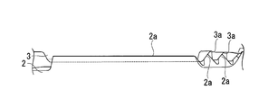
- FIG. 1 It is a schematic diagram for explaining the shape of the shaft portion in the spline connection structure according to an embodiment of the present disclosure, (a) is a view of a tooth groove sandwiched between two teeth viewed from the radial direction of the shaft portion, (B) is a side view of a tooth. It is a schematic diagram for demonstrating the curved state of the tooth surface of the tooth
- FIG. 1 is a schematic diagram of a jet engine 10 to which the spline connection structure 1 of the present embodiment is applied.
- the air flow direction is used as a reference, and the left side in FIG. 1 is referred to as the upstream side, and the right side in FIG. 1 is referred to as the downstream side.
- the jet engine 10 includes a fan 11, a compressor 12, a combustor 13, a high pressure turbine 14, a high pressure shaft 15, a low pressure turbine 16, and a low pressure shaft 17.
- the fan 11 is disposed at the uppermost stream portion of the jet engine 10, and takes in outside air to generate a propulsive force and to supply the compressor 12.
- the fan 11 includes a rotor 11 a connected to the low pressure shaft 17 and driven to rotate by the low pressure shaft 17.
- the rotor 11a includes a cylinder portion (cylinder portion 3 included in a spline connection structure 1 of the present embodiment described later) directly fixed to the low-pressure shaft 17, a disk-shaped disc integrated with the cylinder portion, and an outer periphery of the disc. Fan blades fixed to the section are provided.
- the compressor 12 is disposed on the downstream side of the fan 11, compresses the air taken in by the fan 11, and sends it out to the downstream side.
- the combustor 13 is disposed on the downstream side of the compressor 12 and mixes and burns fuel with the air compressed by the compressor 12 and discharges the combustion gas generated by the combustion to the downstream side.
- the high-pressure turbine 14 is disposed on the downstream side of the combustor 13, receives the combustion gas discharged from the combustor 13, and generates rotational power.
- the high pressure shaft 15 connects the high pressure turbine 14 and the compressor 12, and transmits the rotational power generated by the high pressure turbine 14 to the compressor 12.
- the high-pressure shaft 15 is a hollow shaft through which the low-pressure shaft 17 is inserted.
- the low-pressure turbine 16 is disposed at the most downstream portion of the jet engine 10 and receives the combustion gas that has passed through the high-pressure turbine 14 to generate rotational power.
- the low-pressure turbine 16 includes a rotor 16 a that is connected to the low-pressure shaft 17 and is rotationally driven by the low-pressure shaft 17.
- the rotor 16a has a cylindrical portion (corresponding to a cylindrical portion 3 included in a spline connection structure 1 of the present embodiment described later) directly fixed to the low pressure shaft 17, a disk-shaped disc integrated with the cylindrical portion, a disc Turbine rotor blades fixed to the outer periphery of the turbine.
- the low-pressure shaft 17 connects the low-pressure turbine 16 and the fan 11, and transmits the rotational power generated by the low-pressure turbine 16 to the fan 11.
- teeth are formed at the connection point of the low-pressure turbine 16 to the rotor 16a and the connection point of the fan 11 to the rotor 11a, and these two connection points are the splines of this embodiment. It corresponds to the shaft portion 2 included in the connection structure 1.
- the air taken in by the fan 11 is compressed and sent to the downstream side to obtain a propulsive force, and part of the outside air taken in by the fan 11 is compressed by the compressor 12. Further, the air compressed by the compressor 12 in the combustor 13 is mixed with fuel and burned, whereby combustion gas is generated. This combustion gas also passes through the high-pressure turbine 14 and the low-pressure turbine 16 and is injected downstream to obtain propulsive force.
- FIG. 2 is an exploded perspective view for explaining the spline connection structure 1 of the present embodiment.
- the spline connection structure 1 of the present embodiment is used as a connection structure between the rotor 16a of the low-pressure turbine 16 and the low-pressure shaft 17 and a connection structure between the rotor 11a of the fan 11 and the low-pressure shaft 17 in the jet engine 10 as described above.
- the shaft portion 2 and the cylindrical portion 3 are connected.
- the shaft portion 2 has a plurality of teeth 2a formed on the outer peripheral surface at equal intervals.
- One tooth 2a is formed to extend in the axial direction of the shaft portion 2, and has a substantially trapezoidal cross section.
- the cylindrical portion 3 is a hollow member into which the shaft portion 2 is inserted, and a plurality of grooves 3a into which the plurality of teeth 2a of the shaft portion 2 are fitted are formed on the inner peripheral surface.
- the single groove 3a has a substantially trapezoidal cross section, like the tooth 2a of the shaft portion 2.
- FIG. 3A is a partially enlarged perspective view of the state in which the shaft portion 2 and the cylindrical portion 3 are fitted.
- 3B is a partially enlarged view of the state in which the shaft portion 2 and the tube portion 3 are fitted as seen from the axial direction of the shaft portion 2.
- the teeth 2 a of the shaft portion 2 are fitted into the grooves 3 a of the tube portion 3.
- the shaft portion 2 and the cylindrical portion 3 are fixed in the circumferential direction.
- FIG. 4A is a view of a tooth gap sandwiched between two teeth 2a as viewed from the radial direction of the shaft portion 2, and corresponds to a cross-sectional view taken along the line GA-GA in FIG.
- FIG. 4B is a side view of the tooth 2a.
- the shaft portion 2 has a plurality of teeth 2a arranged in the circumferential direction at equal intervals. For this reason, as shown to (a) of FIG. 4, the tooth surfaces 2b of the adjacent tooth
- the spline connection structure 1 of the present embodiment as shown in FIG.
- the adjacent tooth surfaces 2 b facing each other are seen from the radial direction of the shaft portion 2 in the tooth width direction (FIG. It is curved with the same distance always maintained in the vertical direction). That is, in the spline connection structure 1 of the present embodiment, as shown in FIG. 4A, the separation distance between the tooth surface 2b and the tooth surface 2b at the position A, and the tooth surface 2b and the tooth surface at the position B. 2b and the distance between the tooth surface 2b and the tooth surface 2b at the position C are the same, and the two tooth surfaces 2b are arranged around the shaft portion 2 in the tooth width direction. Curved in the direction.
- the shaft 2 is rotationally driven so that the tooth 2a moves to the right.
- One tooth 2a includes a downstream side (right side of FIG. 4A) and an upstream side (left side of FIG. 4A) of the tooth 2a when the shaft portion 2 is rotationally driven.
- the tooth surface 2b on the downstream side is curved so that the central part in the tooth width direction swells downstream in the movement direction of the tooth 2a.
- the tooth surface 2b on the upstream side is curved so that the center part in the tooth width direction is recessed downstream in the movement direction of the tooth 2a.
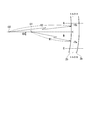
- FIG. 5 is a schematic diagram for explaining the curved state of the tooth surface 2b.
- the tooth surface 2b is curved along an arc having a radius of curvature R1 with the center of curvature O1 as the center. That is, in the spline connection structure 1 of the present embodiment, the tooth surface 2b is curved with a constant curvature radius R1 when viewed from the radial direction of the shaft portion 2.
- the adjacent tooth surfaces 2b facing each other are curved while always maintaining the same distance in the tooth width direction when viewed from the radial direction of the shaft portion 2. For this reason, the curvature radius of all the tooth surfaces 2b is made the same. Therefore, the positions of the respective curvature centers O1 of the adjacent tooth surfaces 2b facing each other are separated in the circumferential direction of the shaft portion 2 by the same distance as the distance between the tooth surfaces 2b.
- the center of curvature O1 is closer to the side where the torque acting on the teeth 2a is smaller than the center position in the tooth width direction (vertical direction in FIG. 5). They are arranged at a distance D3. That is, the position of the center of curvature O1 of the tooth surface 2b is set on the side where the torque acting on the tooth 2a is small in the tooth width direction.
- the curvature center O ⁇ b> 1 has a smaller torque than the center position in the tooth width direction, that is, the rear side of the jet engine 10.
- the position of the center of curvature O1 of the tooth surface 2b is set so as to be displaced to the side where the torque acting on the tooth 2a is small in the tooth width direction, so that the tooth facing the downstream side in the moving direction of the tooth 2a.
- the position T (see FIG. 5) bulging to the most downstream side of the tooth surface 2b is displaced to the side where the torque is smaller than the center position B.
- the difference distance D1 between the position of the tooth surface 2b at the position C spaced apart from the center position B on the side where the torque is larger and the position T is equal to the position between the center position B and the position where the torque is smaller than the center position B.
- the peripheral surface of the shaft portion on which the tooth 2a is formed is a curved surface
- the cross-sectional shape at the center position B is shown in FIG. 6 in the tooth 2a having the curved tooth surface 2b as described above.
- the shaft portion 2 is rotated at an angle ⁇ in the circumferential direction of the shaft portion 2 around the shaft core.
- the cross-sectional shape at the position C is a shape rotated in the circumferential direction of the shaft portion 2 with respect to the cross-sectional shape at the center position B with the shaft core of the shaft portion 2 as the center.
- the degree of curvature of the tooth surface 2b is shown larger than the actual degree of curvature in order to show that the tooth surface 2b of the tooth 2a is curved. ing. Actually, the tooth surface 2b is curved so that the difference distance D2 shown in FIG. For this reason, the tooth surface 2b of the tooth 2a is curved only to such an extent that it cannot be seen through human eyes, and when the shaft portion 2 is inserted into the tube portion 3, the operation of the tooth surface 2b is ignored. It can be carried out.
- Such a shaft portion 2 can be formed in a short time by processing using a hob cutter.
- 7A and 7B are schematic views showing a process of forming the shaft portion 2, FIG. 7A is a perspective view, and FIG. 7B is a plan view.
- the shaft part 2 has a hob cutter 100 that is rotated at a constant speed applied to the peripheral surface, and the hob cutter 100 is moved at a constant speed in the axial direction of the shaft part 2.
- the tooth 2a is formed.
- the shaft portion 2 used in the spline structure 1 of the present embodiment can be formed by appropriately adjusting the rotational acceleration and the moving speed of the hob cutter 100.
- the two tooth surfaces 2b that face each other adjacent to each other in the shaft portion 2 always have the same distance in the tooth width direction when viewed from the radial direction of the shaft portion 2.
- the shaft portion 2 having such a shape is formed by cutting with the hob cutter 100 as described above because the tooth surfaces 2b on both sides of the teeth 2a in the circumferential direction of the shaft portion 2 are similarly curved. can do. Cutting using a hob cutter can form teeth in a shorter time than polishing with a grindstone. Therefore, the shaft portion 2 can be formed in a shorter time than the case where the shaft portion is formed by polishing with a grindstone.
- the shaft portion 2 is subjected to crowning. Therefore, according to the spline connection structure 1 of the present embodiment, it is possible to shorten the processing time of the shaft portion 2 on which crowning has been performed.
- the shaft portion 2 used in the spline connection structure 1 of the present embodiment can be formed using a tool such as a pinion cutter or a shaving cutter.
- the operation for forming the shaft portion 2 is performed. While the time was 1 hour, the working time for forming the shaft portion by grinding with a grindstone was 6 hours. That is, by using the shaft part 2, the working time for forming the shaft part could be reduced to 1/6.
- the tooth surface 2b is curved with a constant radius of curvature R1 when viewed from the radial direction of the shaft portion 2. For this reason, when the shaft portion 2 is formed, the operation can be performed without changing the absolute value of the angular acceleration of the shaft portion 2. Therefore, the shaft portion 2 can be easily formed.
- the position of the curvature center O1 of the tooth surface 2b is set on the side where the torque acting on the tooth 2a is small in the tooth width direction. For this reason, the position T where the tooth surface 2b bulges most is displaced to the side where the torque is small, and the difference distance on the side where the torque is large (the position of the tooth surface 2b at the position T and the position of the tooth surface 2b at the target position). (Distance in the circumferential direction of the shaft portion 2) D1 can be larger than the difference distance D2 on the side where the torque is small. As a result, the tooth surface 2b when the shaft portion 2 is rotated can be made closer to a flat surface, and a large contact area between the shaft portion 2 and the tube portion 3 can be secured.
- the present disclosure is not limited to this, and for example, as shown in FIG. 8, the radius of curvature can be made different between the region Ra on the higher torque side and the region Rb on the lower torque side. is there. That is, it is also possible to act a configuration in which the tooth surface 2b is curved into a shape formed by continuously connecting curves having different curvature radii when viewed from the radial direction of the shaft portion 2.
- the shaft portion 2 can be formed in a short time only by changing the rotation speed of the shaft portion 2 when the shaft portion 2 is cut by the hob cutter 100.
- the torque is larger than the curvature radius R1 of the region Ra on the large torque side.
- the radius of curvature R2 of the small region Rb is set large.
- a curve with a large curvature radius is arranged on the side where the torque acting on the tooth is small, and in the tooth width direction, a curve with a small curvature radius is arranged on the side where the torque acting on the tooth is large.
- the tooth surface 2b is curved so that the formed shape is formed.
- the difference distance on the side where the torque acting on the tooth is large can be made larger than the difference distance on the side where the torque acting on the tooth is small in the tooth width direction. .
- the spline connection structure 1 has been described as applied to the connection point between the low pressure turbine 16 and the low pressure shaft 17 and the connection point between the fan 11 and the low pressure shaft 17.
- the present disclosure is not limited to this.
- the spline connection structure 1 may be applied to a connection point between the high pressure turbine 14 and the high pressure shaft 15 or a connection point between the compressor 12 and the high pressure shaft 15. Is possible.
- the spline connection structure 1 can be applied to a jet engine having a configuration other than the jet engine 10 shown in FIG.
Landscapes
- Engineering & Computer Science (AREA)
- General Engineering & Computer Science (AREA)
- Mechanical Engineering (AREA)
- Ocean & Marine Engineering (AREA)
- Shafts, Cranks, Connecting Bars, And Related Bearings (AREA)
Abstract
本開示は、歯面(2b)にクラウニングが施された複数の歯(2a)が外周面に等間隔で形成された軸部(2)と、軸部(2)の複数の歯(2a)が嵌合される複数の溝(3a)が内周面に形成された筒部(3)と、が接続されてなるスプライン接続構造(1)であって、隣り合って対向する2つの歯面(2a)が、軸部(2)の径方向から見て、歯幅方向にて常に同一距離を保って湾曲されている。
Description
本開示は、スプライン接続構造及びスプラインシャフトに関する。本願は、2015年4月2日に日本に出願された特願2015-075988号に基づき優先権を主張し、その内容をここに援用する。
従来から、航空機用のジェットエンジン等では、シャフトと回転体とを接続する構造としてスプライン接続構造が用いられている。例えば、ファンのロータや低圧タービンのロータが、スプライン接続構造によってシャフトと接続されている。このようなスプライン接続構造は、歯が外周面に等間隔で形成された軸部と、軸部の歯が嵌合される溝が内周面に形成された筒部と、が接続された構造を有している。下記特許文献1~7は、スプライン接続構造及びスプラインシャフトに係る背景技術を開示している。
ところで、航空機のジェットエンジン等では、シャフトに作用するトルクが大きいことから、シャフトが回転しているときにシャフトが僅かに捻じれる。このような場合であっても、軸部の歯の歯面と筒部との接触面を広く確保するため、軸部の歯の片側(回転方向の上流側)の歯面に、クラウニングが施される場合がある。クラウニングとは、軸部の径方向から見て歯面をその中央部が膨らむように湾曲させることを意味し、軸部が捻じれた場合に歯面を平らとするための作業である。
しかしながら、このような歯の片側の歯面にクラウニングが施された軸部では、歯が、片側の歯面のみが湾曲された複雑な形状を有する。そのため、軸部の製造時に歯の両側の歯面を各々砥石で整える作業が必要となる。このような砥石を用いた作業は、一般的に1回の工程で完了するものではなく、目の粗さを変化させながら複数回の工程を要する。このため、従来、軸部の製造は、非常に長い時間を要する。
本開示は、上述する問題点に鑑みてなされたもので、クラウニングが施された歯を有する軸部の加工時間を短縮することが可能なスプライン接続構造を提案することを目的とする。
本開示は、上記課題を解決するための手段として、以下の構成を採用する。
本開示の第1の態様は、歯面にクラウニングが施された複数の歯が外周面に等間隔で形成された軸部と、軸部の複数の歯が嵌合される複数の溝が内周面に形成された筒部とが接続されてなるスプライン接続構造であって、隣り合って対向する2つの歯面が、軸部の径方向から見て、歯幅方向にて常に同一距離を保って湾曲されている。なお、歯幅方向とは、スプライン接続構造の軸芯(軸部の軸芯)方向と平行な方向を意味する。
本開示の第2の態様は、上記第1の態様であるスプライン接続構造を用いたスプラインシャフトである。
本開示によれば、軸部において隣り合って対向する2つの歯面が、軸部の径方向から見て、歯幅方向に常に同一距離を保って湾曲されている。このような形状の軸部では、歯の両側の歯面が同じように湾曲された形状となることから、ホブカッタで軸部の周面を切削することによって歯を形成することができる。通常、ホブカッタを用いた切削では、ホブカッタを軸部の軸芯方向に沿うように一定速度で回転させながら軸部の周面に接触させ、且つ、軸部を回転させながら軸芯方向に移動させることによって、軸部の周面を切削する。これにより、砥石による研磨と比較して短時間で直線状に歯を形成する。これに加え、軸部の回転速度を途中で連続的に変化させることによって、本来形成される直線状の歯の代わりに湾曲状の歯を形成することができる。したがって、ホブカッタにより軸部の周面を切削している途中に軸部の回転速度を連続的に変化させることによって、歯の両側の歯面が同じように湾曲された形状を備える本開示の軸部を短時間で形成することができる。これに加えて、歯の片側の歯面が、軸芯方向における中央部が膨らむように湾曲した面となることから、クラウニングが施された軸部を形成することができる。したがって、本開示によれば、スプライン接続構造に用いられるクラウニングが施された軸部の加工時間を短縮することが可能となる。
以下、図面を参照して、本開示に係るスプライン接続構造の一実施形態について説明する。なお、以下の図面において、各部材を認識可能な大きさとするために、各部材の縮尺を適宜変更している。
図1は、本実施形態のスプライン接続構造1が適用されるジェットエンジン10の模式図である。なお、以下の説明においては、空気の流れ方向を基準とし、図1の左側を上流側、図1の右側を下流側と称する。この図1に示すように、ジェットエンジン10は、ファン11と、圧縮機12と、燃焼器13と、高圧タービン14と、高圧シャフト15と、低圧タービン16と、低圧シャフト17とを備えている。ファン11は、ジェットエンジン10の最上流部に配置されており、推進力を生み出すと共に圧縮機12に供給するための外気を取り込む。このファン11は、低圧シャフト17と接続され、低圧シャフト17によって回転駆動されるロータ11aを備えている。このロータ11aは、低圧シャフト17に直接固定される筒部(後述する本実施形態のスプライン接続構造1に含まれる筒部3)、筒部と一体化される円板状のディスク、ディスクの外周部に固定されるファン動翼等を備えている。
圧縮機12は、ファン11の下流側に配置されており、ファン11によって取り込まれた空気を圧縮して下流側に送り出す。燃焼器13は、圧縮機12の下流側に配置されており、燃料を圧縮機12によって圧縮された空気と混合して燃焼させると共に、燃焼によって生成された燃焼ガスを下流側に排出する。高圧タービン14は、燃焼器13の下流側に配置されており、燃焼器13から排出された燃焼ガスを受けて回転動力を生成する。高圧シャフト15は、高圧タービン14と圧縮機12とを接続しており、高圧タービン14で生成された回転動力を圧縮機12に伝達する。この高圧シャフト15は、低圧シャフト17が内部に挿通される中空のシャフトとされている。
低圧タービン16は、ジェットエンジン10の最下流部に配置されており、高圧タービン14を通過した燃焼ガスを受けて回転動力を生成する。この低圧タービン16は、低圧シャフト17と接続され且つ低圧シャフト17によって回転駆動されるロータ16aを備えている。このロータ16aは、低圧シャフト17に直接固定される筒部(後述する本実施形態のスプライン接続構造1に含まれる筒部3に相当)、筒部と一体化される円板状のディスク、ディスクの外周部に固定されるタービン動翼等を備えている。
低圧シャフト17は、低圧タービン16とファン11とを接続しており、低圧タービン16で生成された回転動力をファン11に伝達する。この低圧シャフト17のうち、低圧タービン16のロータ16aとの接続箇所と、ファン11のロータ11aとの接続箇所と、に歯が形成されており、この2つの接続箇所が、本実施形態のスプライン接続構造1に含まれる軸部2に相当する。
このようなジェットエンジン10では、ファン11によって取り込まれた空気を圧縮して下流側に送り出すことで推進力を得ると共に、ファン11によって取り込まれた外気の一部が圧縮機12で圧縮される。また、燃焼器13において圧縮機12で圧縮された空気が燃料と混合されると共に燃焼されることで、燃焼ガスが生成される。この燃焼ガスが高圧タービン14と低圧タービン16とを通過して下流に噴射されることによっても、推進力を得ている。
図2は、本実施形態のスプライン接続構造1を説明するための分解斜視図である。本実施形態のスプライン接続構造1は、上述のようなジェットエンジン10において、低圧タービン16のロータ16aと低圧シャフト17との接続構造及びファン11のロータ11aと低圧シャフト17との接続構造として用いられており、軸部2と筒部3とを接続する構造である。
軸部2は、外周面に等間隔で形成された複数の歯2aを有している。1つの歯2aは、軸部2の軸芯方向に延びて形成されており、断面が略台形状とされている。筒部3は、軸部2が内部に挿通される中空部材であり、内周面に軸部2の複数の歯2aが嵌合される複数の溝3aが形成されている。この1つの溝3aは、軸部2の歯2aと同様に、断面が略台形状とされている。図3Aは、軸部2と筒部3とが嵌合された状態の部分拡大図斜視図である。また、図3Bは、軸部2と筒部3とが嵌合された状態を軸部2の軸芯方向から見た部分拡大図である。これらの図3A及び図3Bに示すように、軸部2が筒部3に挿入されると、軸部2の歯2aが筒部3の溝3aに嵌合される。これによって、軸部2と筒部3とが、周方向に固定される。
図4の(a)及び図4の(b)は、軸部2の形状を説明するための模式図である。図4の(a)が2つの歯2aに挟まれる歯溝を軸部2の径方向から見た図であり、図4の(b)のGA-GA線断面図に相当する。図4の(b)が歯2aの側面図である。軸部2は、複数の歯2aが等間隔で周方向に配列されている。このため、図4の(a)に示すように、隣り合う歯2aの歯面2b同士が対向して配置される。本実施形態のスプライン接続構造1では、図4(a)のに示すように、隣り合って対向する歯面2bが、軸部2の径方向から見て、歯幅方向(図4の(a)の上下方向)にて常に同一距離を保って湾曲されている。つまり、本実施形態のスプライン接続構造1では、図4の(a)に示すように、Aの位置における歯面2bと歯面2bとの離間距離と、Bの位置における歯面2bと歯面2bとの離間距離と、Cの位置における歯面2bと歯面2bとの離間距離と、が同一とされた状態で、2つの歯面2bが、歯幅方向に渡って軸部2の周方向に向けて湾曲されている。
また、図4の(a)において、軸部2は、歯2aが右側に移動するように回転駆動される。1つの歯2aには、軸部2が回転駆動されるときの歯2aの移動方向の下流側(図4の(a)の右側)と上流側(図4の(a)の左側)とに歯面2bが存在する。本実施形態のスプライン接続構造1では、歯幅方向の中央部が歯2aの移動方向の下流側に膨出するように下流側の歯面2bが湾曲されている。なお、上流側の歯面2bは、歯幅方向の中央部が歯2aの移動方向の下流側に凹むように湾曲されている。
図5は、歯面2bの湾曲状態を説明するための模式図である。この図5に示すように、この歯面2bは、曲率中心O1を中心とし、曲率半径R1の円弧に沿って湾曲されている。つまり、本実施形態のスプライン接続構造1では、歯面2bは、軸部2の径方向から見て一定の曲率半径R1で湾曲されている。なお、本実施形態のスプライン接続構造1では、隣り合って対向する歯面2bが、軸部2の径方向から見て、歯幅方向にて常に同一距離を保って湾曲されている。このため、全ての歯面2bの曲率半径が同一とされている。よって、隣り合って対向する歯面2bの各々の曲率中心O1の位置は、歯面2b同士の離間距離と同一距離分、軸部2の周方向に離間している。
また、本実施形態のスプライン接続構造1では、図5に示すように、曲率中心O1が、歯幅方向(図5の上下方向)の中心位置よりも、歯2aに作用するトルクが小さい側に距離D3だけ寄って配置されている。つまり、歯面2bの曲率中心O1の位置は、歯幅方向にて歯2aに作用するトルクの小さい側に設定されている。
例えば、低圧タービン16と低圧シャフト17との接続箇所では、回転動力を生成する低圧タービン16の複数の動翼列が低圧シャフト17の軸芯方向に配列されていることから、ジェットエンジン10の前方に向かうほどトルクが増大して歯2aに大きなトルクが作用する。このため、低圧タービン16と低圧シャフト17との接続箇所に適用されるスプライン接続構造1では、曲率中心O1は、歯幅方向の中心位置よりもトルクが小さい側、すなわち、ジェットエンジン10の後方側に設定されている。また、ファン11と低圧シャフト17との接続箇所では、回転動力を消費して回転されるファン11の複数の動翼列が低圧シャフト17の軸芯方向に設置されていることから、ジェットエンジン10の前方に向かうほどトルクが減少して歯2aに作用するトルクが小さくなる。このため、ファン11と低圧シャフト17との接続箇所に適用されるスプライン接続構造1では、曲率中心O1は、歯幅方向の中心位置よりもトルクが小さい側、すなわち、ジェットエンジン10の前方側に設定されている。
このように、歯面2bの曲率中心O1の位置が、歯幅方向にて歯2aに作用するトルクの小さい側に変位して設定されることによって、歯2aの移動方向の下流側に向く歯面2bにおいて、歯面2bの最も下流側に膨出する位置T(図5を参照)が中心位置Bよりもトルクが小さい側に変位する。この結果、中心位置Bよりもトルクの大きい側に離間した位置Cにおける歯面2bの位置と、位置Tと、の差分距離D1は、中心位置Bよりもトルクの小さい側に中心位置Bと位置Cとの間の距離と等しい距離離間した位置Aにおける歯面2bの位置と、上記位置Tと、の差分距離D2よりも大きくなる。軸部2は、歯2aに作用するトルクが大きい箇所で捩れ角が大きくなるため、差分距離D1を差分距離D2よりも大きくすることによって、回転移動中の歯面2bをより平面に近づけることが可能となる。
また、歯2aが形成される軸部の周面は湾曲面であることから、上述のように湾曲された歯面2bを有する歯2aでは、中心位置Bでの断面形状が、図6に示すように、位置Aでの断面形状に対して、軸部2の軸芯を中心として軸部2の周方向に角度αで回転した形状とされている。同様に、位置Cでの断面形状は、中心位置Bでの断面形状に対して、軸部2の軸芯を中心として軸部2の周方向に回転した形状とされている。
なお、図4~図6の模式図では、歯2aの歯面2bが湾曲されていることを分かりやすく示すために、歯面2bの湾曲の程度を実際の湾曲の程度よりも大きくして示している。実際には、図5に示す差分距離D2が1000分の数mm程度となるように歯面2bは湾曲されている。このため、歯2aの歯面2bは、人間の目を介して視認できない程度でしか湾曲されておらず、軸部2を筒部3に挿入するときには歯面2bの湾曲を無視して作業を行うことができる。
このような軸部2は、ホブカッタを用いた加工によって短時間で形成することができる。図7A及び図7Bは、軸部2の形成工程を示す模式図であり、図7Aが斜視図であり、図7Bが平面図である。これらの図7A及び図7Bに示すように、軸部2は、一定速度で回転されるホブカッタ100が周面に当てられ、ホブカッタ100が軸部2の軸芯方向に一定速度で移動されることによって歯2aが形成される。この時、ホブカッタ100の回転加速度及び移動速度を適宜調整することで、本実施形態のスプライン構造1で用いられる軸部2を形成することができる。
以上のような本実施形態のスプライン接続構造1によれば、軸部2において隣り合って対向する2つの歯面2bが、軸部2の径方向から見て、歯幅方向に常に同一距離を保って湾曲されている。このような形状の軸部2は、軸部2の周方向における歯2aの両側の歯面2bが同じように湾曲された形状となることから、上述のようにホブカッタ100で切削することによって形成することができる。ホブカッタを用いた切削は、砥石による研磨と比較して短時間で歯を形成することができる。したがって、軸部2は、砥石による研磨によって軸部を形成する場合と比較して短時間で形成することができる。また、軸部2の歯2aの下流側の歯面2bが、その中央部が膨らむように湾曲した面となることから、軸部2はクラウニングが施されたものとなる。したがって、本実施形態のスプライン接続構造1によれば、クラウニングが施された軸部2の加工時間を短縮することが可能となる。その他、ピニオンカッタ、シェービングカッタなどの工具を使っても、本実施形態のスプライン接続構造1で用いられる軸部2を形成することができる。
なお、軸部2を形成するための作業時間と、軸部2と同一サイズの軸部を砥石による研磨により形成するための作業時間と、を比較したところ、軸部2を形成するための作業時間が1時間であったのに対して、砥石による研磨によって軸部を形成するための作業時間は6時間であった。つまり、軸部2を用いることによって、軸部の形成のための作業時間を6分の1に短縮することができた。
また、本実施形態のスプライン接続構造1においては、歯面2bは、軸部2の径方向から見て一定の曲率半径R1で湾曲されている。このため、軸部2を形成するときに、軸部2の角加速度の絶対値を変化させることなく作業を進めることができる。したがって、軸部2の形成を容易に行うことが可能となる。
また、本実施形態のスプライン接続構造1においては、歯面2bの曲率中心O1の位置は、歯幅方向にて歯2aに作用するトルクの小さい側に設定されている。このため、歯面2bの最も膨出する位置Tがトルクの小さい側に変位し、トルクが大きい側での差分距離(位置Tでの歯面2bの位置と対象位置での歯面2bの位置との軸部2の周方向における距離)D1をトルクが小さい側での差分距離D2よりも大きくすることができる。これによって軸部2が回転されているときの歯面2bを、より平面に近づけることができ、軸部2と筒部3との接触面積を広く確保することが可能となる。
以上、図面を参照しながら本開示の好適な実施形態について説明したが、本開示は上記実施形態に限定されるものではない。上述した実施形態において示した各構成部材の諸形状や組み合わせ等は一例であって、本開示の趣旨から逸脱しない範囲において設計要求等に基づき種々変更可能である。
例えば、上記実施形態においては、歯面2bが一定の曲率半径R1で湾曲された構成を採用した。しかしながら、本開示はこれに限定されるものではなく、例えば、図8に示すように、トルクが大きい側の領域Raとトルクが小さい側の領域Rbとにおいて、曲率半径を異ならせることも可能である。つまり、歯面2bが、軸部2の径方向から見て、曲率半径が異なる曲線が連続的に接続されてなる形状に湾曲されている構成を作用することも可能である。このような構成を採用することによって、軸部2が回転するときに歯面2bがより平面に近づくように、歯面2bの形状をより柔軟に変化させることが可能となる。このような場合であっても、軸部2は、ホブカッタ100による軸部2の切削時において軸部2の回転速度を変化させるのみで短時間で形成することができる。
なお、上述のようにトルクが大きい側の領域Raとトルクが小さい側の領域Rbとにおいて、曲率半径を異ならせる場合には、例えばトルクが大きい側の領域Raの曲率半径R1よりも、トルクが小さい側の領域Rbの曲率半径R2を大きく設定する。つまり、歯幅方向にて、歯に作用するトルクの小さい側に、曲率半径が大きな曲線が配置され、歯幅方向にて、歯に作用するトルクの大きい側に、曲率半径が小さい曲線が配置された形状が形成されるように、歯面2bを湾曲する。これによって、歯幅方向にて、歯に作用するトルクの大きい側での上記差分距離を、歯幅方向にて、歯に作用するトルクの小さい側での上記差分距離よりも大きくすることができる。これにより、回転移動中の歯面2bをより平面に近づけることが可能となる。
また、上記実施形態においては、本実施形態のスプライン接続構造1を、低圧タービン16と低圧シャフト17との接続箇所と、ファン11と低圧シャフト17との接続箇所に適用する例について説明した。しかしながら、本開示はこれに限定されるものではなく、例えば、高圧タービン14と高圧シャフト15との接続箇所や圧縮機12と高圧シャフト15との接続箇所に、スプライン接続構造1を適用することも可能である。また、図1に示すジェットエンジン10以外の構成のジェットエンジンに、スプライン接続構造1を適用することも可能である。また、ジェットエンジン以外の装置にスプライン接続構造1を適用することも可能である。
本開示のスプライン接続構造によれば、スプライン接続構造に用いられるクラウニングが施された軸部の加工時間を短縮することが可能となる。
1 スプライン接続構造
2 軸部
2a 歯
2b 歯面
3 筒部
3a溝
10 ジェットエンジン
11 ファン
11a ロータ
12 圧縮機
13 燃焼器
14 高圧タービン
15 高圧シャフト
16 低圧タービン
16a ロータ
17……低圧シャフト
100……ホブカッタ
2 軸部
2a 歯
2b 歯面
3 筒部
3a溝
10 ジェットエンジン
11 ファン
11a ロータ
12 圧縮機
13 燃焼器
14 高圧タービン
15 高圧シャフト
16 低圧タービン
16a ロータ
17……低圧シャフト
100……ホブカッタ
Claims (6)
- 歯面にクラウニングが施された複数の歯が外周面に等間隔で形成された軸部と、前記軸部の前記複数の歯が嵌合される複数の溝が内周面に形成された筒部と、が接続されてなるスプライン接続構造であって、
隣り合って対向する2つの前記歯面が、前記軸部の径方向から見て、歯幅方向にて常に同一距離を保って湾曲されているスプライン接続構造。 - 前記歯面は、前記軸部の径方向から見て一定の曲率半径で湾曲されている請求項1記載のスプライン接続構造。
- 前記歯面の曲率中心の位置は、前記歯幅方向にて前記歯に作用するトルクの小さい側に設定されている請求項2記載のスプライン接続構造。
- 前記歯面は、前記軸部の径方向から見て、曲率半径が異なる曲線が連続的に接続されてなる形状に湾曲されている請求項1記載のスプライン接続構造。
- 前記歯幅方向にて、前記歯幅方向にて前記歯に作用するトルクの小さい側に曲率半径が大きな曲線が配置されている請求項4記載のスプライン接続構造。
- 請求項1~5のいずれか一項に記載のスプライン接続構造を用いたスプラインシャフト。
Priority Applications (2)
| Application Number | Priority Date | Filing Date | Title |
|---|---|---|---|
| EP16771920.2A EP3232075B1 (en) | 2015-04-02 | 2016-02-15 | Spline connection structure and spline shaft |
| US15/646,319 US10247247B2 (en) | 2015-04-02 | 2017-07-11 | Spline connection structure and spline shaft |
Applications Claiming Priority (2)
| Application Number | Priority Date | Filing Date | Title |
|---|---|---|---|
| JP2015-075988 | 2015-04-02 | ||
| JP2015075988A JP6540167B2 (ja) | 2015-04-02 | 2015-04-02 | スプライン接続構造及びスプラインシャフト |
Related Child Applications (1)
| Application Number | Title | Priority Date | Filing Date |
|---|---|---|---|
| US15/646,319 Continuation US10247247B2 (en) | 2015-04-02 | 2017-07-11 | Spline connection structure and spline shaft |
Publications (1)
| Publication Number | Publication Date |
|---|---|
| WO2016158036A1 true WO2016158036A1 (ja) | 2016-10-06 |
Family
ID=57004902
Family Applications (1)
| Application Number | Title | Priority Date | Filing Date |
|---|---|---|---|
| PCT/JP2016/054270 Ceased WO2016158036A1 (ja) | 2015-04-02 | 2016-02-15 | スプライン接続構造及びスプラインシャフト |
Country Status (4)
| Country | Link |
|---|---|
| US (1) | US10247247B2 (ja) |
| EP (1) | EP3232075B1 (ja) |
| JP (1) | JP6540167B2 (ja) |
| WO (1) | WO2016158036A1 (ja) |
Cited By (1)
| Publication number | Priority date | Publication date | Assignee | Title |
|---|---|---|---|---|
| JP2022129698A (ja) * | 2021-02-25 | 2022-09-06 | Ntn株式会社 | 車輪用軸受装置および動力伝達構造 |
Families Citing this family (4)
| Publication number | Priority date | Publication date | Assignee | Title |
|---|---|---|---|---|
| WO2018070180A1 (ja) * | 2016-10-11 | 2018-04-19 | 日立オートモティブシステムズ株式会社 | プロペラシャフト及びその製造方法 |
| US10975915B2 (en) * | 2018-01-08 | 2021-04-13 | Raytheon Technologies Corporation | Assembly alignment handling damage tolerant spline |
| DE102019210419A1 (de) * | 2019-07-15 | 2021-01-21 | Rolls-Royce Deutschland Ltd & Co Kg | Wellenverbindung |
| FR3153370A1 (fr) * | 2023-09-22 | 2025-03-28 | Safran Aircraft Engines | Pièce tournante pour turbomachine d’aéronef |
Citations (4)
| Publication number | Priority date | Publication date | Assignee | Title |
|---|---|---|---|---|
| US5533825A (en) * | 1994-11-14 | 1996-07-09 | General Electric Company | Parabolically helical spline shaft coupling |
| JPH0925941A (ja) * | 1995-07-11 | 1997-01-28 | Aichi Mach Ind Co Ltd | スプライン嵌合構造 |
| JP2002327771A (ja) * | 2001-05-02 | 2002-11-15 | Ishikawajima Harima Heavy Ind Co Ltd | スプライン継手 |
| JP2007247771A (ja) * | 2006-03-15 | 2007-09-27 | Ntn Corp | トルク伝達機構 |
Family Cites Families (18)
| Publication number | Priority date | Publication date | Assignee | Title |
|---|---|---|---|---|
| US1381805A (en) * | 1919-12-09 | 1921-06-14 | Courtaulds Ltd | Spinning-box mounting |
| US1443837A (en) * | 1920-01-10 | 1923-01-30 | Newark Gearcutting Machine Co | Sinusoidal gearing |
| JPS6345223U (ja) | 1986-09-04 | 1988-03-26 | ||
| JPH0633220Y2 (ja) | 1986-09-04 | 1994-08-31 | エヌティエヌ株式会社 | 車両用駆動力伝達構造 |
| GB8711700D0 (en) * | 1987-05-18 | 1987-06-24 | Green P C | Mechanical coupling |
| US4875796A (en) * | 1987-11-23 | 1989-10-24 | Eaton Corporation | Press-fit splined connection |
| JP3052037B2 (ja) | 1993-07-22 | 2000-06-12 | 本田技研工業株式会社 | スプライン結合構造 |
| US5580183A (en) | 1994-04-29 | 1996-12-03 | United Technologies Corporation | Gas turbine engine spline arrangement |
| JPH09141354A (ja) | 1995-11-20 | 1997-06-03 | Aisin Seiki Co Ltd | 中空シャフトの高歯たけスプライン製造方法および高歯たけスプラインを備えた中空シャフト |
| DE19613462C2 (de) * | 1996-04-04 | 1999-10-14 | Hubert Taubert | Gelenkverbindung zur Drehübertragung |
| JP2005009615A (ja) | 2003-06-20 | 2005-01-13 | Ntn Corp | 動力伝達部材のスプライン嵌合構造 |
| US7040870B2 (en) * | 2003-12-30 | 2006-05-09 | The Goodyear Tire & Rubber Company | Gear pump with gears having curved teeth and method of feeding elastomeric material |
| US7288029B1 (en) * | 2005-01-19 | 2007-10-30 | Gkn Driveline North America, Inc. | Propshaft with crash-worthiness |
| US7493754B2 (en) | 2005-10-19 | 2009-02-24 | General Electric Company | Gas turbine engine assembly and methods of assembling same |
| JP2007198401A (ja) | 2006-01-23 | 2007-08-09 | Ntn Corp | スプライン連結構造、動力伝達シャフト、等速自在継手の外輪ステム |
| JP5093003B2 (ja) | 2008-08-29 | 2012-12-05 | トヨタ自動車株式会社 | スプラインシャフト、及び、スプラインシャフトの製造方法 |
| US8348542B2 (en) * | 2009-04-13 | 2013-01-08 | Gandy Technologies Corporation | Connection system for tubular members |
| US9382001B2 (en) * | 2014-07-23 | 2016-07-05 | Bell Helicopter Textron Inc. | Torque transfer system for a rotorcraft |
-
2015
- 2015-04-02 JP JP2015075988A patent/JP6540167B2/ja active Active
-
2016
- 2016-02-15 WO PCT/JP2016/054270 patent/WO2016158036A1/ja not_active Ceased
- 2016-02-15 EP EP16771920.2A patent/EP3232075B1/en active Active
-
2017
- 2017-07-11 US US15/646,319 patent/US10247247B2/en active Active
Patent Citations (4)
| Publication number | Priority date | Publication date | Assignee | Title |
|---|---|---|---|---|
| US5533825A (en) * | 1994-11-14 | 1996-07-09 | General Electric Company | Parabolically helical spline shaft coupling |
| JPH0925941A (ja) * | 1995-07-11 | 1997-01-28 | Aichi Mach Ind Co Ltd | スプライン嵌合構造 |
| JP2002327771A (ja) * | 2001-05-02 | 2002-11-15 | Ishikawajima Harima Heavy Ind Co Ltd | スプライン継手 |
| JP2007247771A (ja) * | 2006-03-15 | 2007-09-27 | Ntn Corp | トルク伝達機構 |
Cited By (2)
| Publication number | Priority date | Publication date | Assignee | Title |
|---|---|---|---|---|
| JP2022129698A (ja) * | 2021-02-25 | 2022-09-06 | Ntn株式会社 | 車輪用軸受装置および動力伝達構造 |
| JP7610427B2 (ja) | 2021-02-25 | 2025-01-08 | Ntn株式会社 | 車輪用軸受装置および動力伝達構造 |
Also Published As
| Publication number | Publication date |
|---|---|
| EP3232075A4 (en) | 2018-05-23 |
| JP6540167B2 (ja) | 2019-07-10 |
| US20170307023A1 (en) | 2017-10-26 |
| EP3232075A1 (en) | 2017-10-18 |
| EP3232075B1 (en) | 2019-10-02 |
| JP2016196902A (ja) | 2016-11-24 |
| US10247247B2 (en) | 2019-04-02 |
Similar Documents
| Publication | Publication Date | Title |
|---|---|---|
| WO2016158036A1 (ja) | スプライン接続構造及びスプラインシャフト | |
| RU2341660C2 (ru) | Лопатка двойной кривизны для направляющего аппарата турбомашины | |
| JP4125725B2 (ja) | ガスタービンエンジン用の中空ファンブレード | |
| EP2500525B1 (en) | Damper pin | |
| EP2500524B1 (en) | Gas turbine engine blade and corresponding assemblage | |
| US20090304473A1 (en) | Method for the milling of blisks | |
| EP2971736B1 (en) | Interblade metal platform for ceramic matrix composite turbine blades | |
| US9932834B2 (en) | Rotor blade with a conic spline fillet at an intersection between a platform and a neck | |
| JP6330443B2 (ja) | スカイビング用カッター、及び歯車 | |
| EP3715640B1 (en) | Compressor section of gas turbine engine including shroud with serrated casing treatment | |
| EP2762676A1 (en) | Turbomachine rotor blade, turbomachine rotor disc, turbomachine rotor, and gas turbine engine with different root and slot contact face angles | |
| US20120128497A1 (en) | Turbine engine compressor stator | |
| JP4102806B2 (ja) | ガスタービンエンジン用の中空ファンブレード | |
| JP5810376B2 (ja) | 軸受シェルの構造化された滑り面を機械加工するための工具及び方法 | |
| JP2005264928A (ja) | ガスタービンエンジン用の中空ファンブレード | |
| US9897001B2 (en) | Compressor areas for high overall pressure ratio gas turbine engine | |
| JP2013245822A (ja) | シールおよびシールの形成方法 | |
| EP2971523B1 (en) | Attachment feature of a gas turbine engine blade having a curved profile | |
| US9896947B2 (en) | Turbine airfoil attachment with multi-radial serration profile | |
| JP2020537076A (ja) | 排気ガス過給機のための羽根車、排気ガス過給機、及び排気ガス過給機のための回転体アセンブリのバランス調整方法 | |
| CA2991829A1 (en) | Crowning of a spline in a direction perpendicular to a spline tooth face | |
| JP6992504B2 (ja) | インペラの製造方法 | |
| US9682756B1 (en) | System for composite marine propellers | |
| JP2008133959A (ja) | ターボ機械における2個の回転シャフトの結合装置 |
Legal Events
| Date | Code | Title | Description |
|---|---|---|---|
| 121 | Ep: the epo has been informed by wipo that ep was designated in this application |
Ref document number: 16771920 Country of ref document: EP Kind code of ref document: A1 |
|
| REEP | Request for entry into the european phase |
Ref document number: 2016771920 Country of ref document: EP |
|
| NENP | Non-entry into the national phase |
Ref country code: DE |