WO2016158751A1 - Couche-culotte d'apprentissage jetable - Google Patents
Couche-culotte d'apprentissage jetable Download PDFInfo
- Publication number
- WO2016158751A1 WO2016158751A1 PCT/JP2016/059625 JP2016059625W WO2016158751A1 WO 2016158751 A1 WO2016158751 A1 WO 2016158751A1 JP 2016059625 W JP2016059625 W JP 2016059625W WO 2016158751 A1 WO2016158751 A1 WO 2016158751A1
- Authority
- WO
- WIPO (PCT)
- Prior art keywords
- sheet layer
- elastic film
- holes
- pants
- type disposable
- Prior art date
- Legal status (The legal status is an assumption and is not a legal conclusion. Google has not performed a legal analysis and makes no representation as to the accuracy of the status listed.)
- Ceased
Links
Images






Classifications
-
- A—HUMAN NECESSITIES
- A61—MEDICAL OR VETERINARY SCIENCE; HYGIENE
- A61F—FILTERS IMPLANTABLE INTO BLOOD VESSELS; PROSTHESES; DEVICES PROVIDING PATENCY TO, OR PREVENTING COLLAPSING OF, TUBULAR STRUCTURES OF THE BODY, e.g. STENTS; ORTHOPAEDIC, NURSING OR CONTRACEPTIVE DEVICES; FOMENTATION; TREATMENT OR PROTECTION OF EYES OR EARS; BANDAGES, DRESSINGS OR ABSORBENT PADS; FIRST-AID KITS
- A61F13/00—Bandages or dressings; Absorbent pads
- A61F13/15—Absorbent pads, e.g. sanitary towels, swabs or tampons for external or internal application to the body; Supporting or fastening means therefor; Tampon applicators
- A61F13/45—Absorbent pads, e.g. sanitary towels, swabs or tampons for external or internal application to the body; Supporting or fastening means therefor; Tampon applicators characterised by the shape
- A61F13/49—Absorbent pads, e.g. sanitary towels, swabs or tampons for external or internal application to the body; Supporting or fastening means therefor; Tampon applicators characterised by the shape specially adapted to be worn around the waist, e.g. diapers, nappies
Definitions
- the present invention relates to a pants-type disposable diaper having an elastic film stretchable structure in which an elastic film is sandwiched between sheet layers.
- the pants-type disposable diaper includes an exterior body that individually or integrally configures the front body and the back body, and an interior body including an absorbent body that is attached to the inner surface of the exterior body so as to extend from the front body to the back body.
- a waist opening and a pair of left and right leg openings are formed by joining the side edges of the outer body of the front body and the side edges of the outer body of the rear body to form a side seal part. Is.
- the exterior body has a waist region defined as a front-rear direction range (a front-rear direction range extending from the waist opening to the upper end of the leg opening) having a side seal portion, and an intermediate region defined as a front-rear direction range of a portion forming the leg opening.
- the intermediate region has a cover portion located on the side of the interior body, and it is common to form a stretchable region in the waistline region or the cover portion (for example, Patent Document 1, 2).
- An elastic structure in which this elastic film is sandwiched between sheet layers (hereinafter also referred to as an elastic film elastic structure) is formed by laminating an elastic film between a first sheet layer whose elastic region is made of a nonwoven fabric and a second sheet layer made of a nonwoven fabric.
- the first sheet layer and the second sheet layer are arranged at intervals in the stretch direction and the direction orthogonal thereto, with the elastic film being stretched in the stretch direction along the surface thereof.
- a large number of joints are joined through through holes formed in the elastic film.
- an elastic film stretchable structure in the natural length state, as the elastic film contracts between the joints, the interval between the joints becomes narrower, and the stretches between the joints in the first sheet layer and the second sheet layer.
- a contraction fold is formed that extends in a direction that intersects the direction.
- the elastic film is stretched between the joints when stretched, the spacing between the joints and the shrinkage wrinkles in the first sheet layer and the second sheet layer are widened, and the first sheet layer and the second sheet layer are completely developed. Elastic extension to the state becomes possible.
- This elastic film stretchable structure is excellent in surface fit, and there is no bonding between the first sheet layer and the second sheet layer and the elastic film, and the first sheet layer and the second sheet layer are extremely bonded. Since there are few, it is very flexible, and there exists an advantage that the through-hole of an elastic film contributes also to air permeability improvement.
- the elastic film has a sufficiently large number of through holes, but a large number of through holes are formed in the elastic film. This is the same as if the elastic film is perforated in all directions, and if it is pulled strongly in a specific direction, the part between the through holes breaks, and the stretched part loses elasticity. There is a fear.
- the stretchable area may be strongly extended obliquely upward, for example, when the crotch part is caught on the heel, toe, or knee, etc. In such a case, there is a high possibility that the elastic film is partially broken and loses stretchability at the broken portion.
- the main problem of the present invention is to prevent the elastic film from breaking when the pants-type disposable diaper is worn.
- the present invention that has solved the above problems is as follows.
- ⁇ Invention of Claim 1> An exterior body that individually or integrally configures the front body and the back body, and an absorbent body provided inside the exterior body so as to extend from the front body to the back body,
- a pants-type disposable diaper having a waist opening and a pair of left and right leg openings formed by joining side edges of the outer body of the front body and both side edges of the outer body of the rear body to form a side seal part
- the exterior body in at least one of the front body and the back body has stretch regions that elastically stretch in the width direction on at least both sides in the width direction, At least the stretch region is a state in which an elastic film is laminated between a first sheet layer made of nonwoven fabric and a second sheet layer made of nonwoven fabric, and the elastic film is stretched in the stretch direction of the stretch region Then, the first sheet layer and the second sheet layer are joined through a through hole formed in the elastic film at a plurality of joining portions arranged at intervals in the expansion
- the shape of the through hole in the natural length state is an inclined shape that is long in one direction and has an inclination angle of 25 to 35 degrees determined as an intersection angle on the center side in the width direction among the intersection angles of the longitudinal direction and the width direction of the diaper. It is said that A pants-type disposable diaper characterized by that.
- the direction of the force when the stretchable region is strongly extended obliquely upward due to the crotch portion being caught on the heel, toes, knees, etc. is relative to the width direction.
- the crossing angle on the outer side in the width direction is about 55 to 65 degrees. In a normal pants-type disposable diaper, this angle is the angle in the direction connecting the side edge of the crotch part and the end of the side seal part on the waist side in a flat state where the front and back bodies are overlapped. It is determined from the fact that most of them are within the range.
- the through holes having an inclined shape that is long in the direction perpendicular to the direction in which force is applied as in the present invention may have the same area and arrangement of the individual through holes as compared to the case of a perfect circle or square.
- the through-holes of the elastic film do not have other through-holes closest to each other in a range of 55 to 65 degrees at a central angle with the width direction outside as 0 degrees centering on the through-holes.
- Pants-type disposable diapers are not have other through-holes closest to each other in a range of 55 to 65 degrees at a central angle with the width direction outside as 0 degrees centering on the through-holes.
- the elastic film can be made more difficult to break by preventing the through holes from being arranged at a short distance in the direction in which a strong force is applied.
- a large number of through-holes provided in the stretchable region are each of the through-holes and other through-holes located in the range of 55 to 65 degrees with a central angle of 0 degrees in the width direction outside the through hole.
- the planar arrangement of the through holes is an orthorhombic lattice arrangement, a hexagonal lattice arrangement, a tetragonal lattice arrangement, a rectangular lattice arrangement, a parallel body lattice arrangement, and any of these is less than 90 degrees with respect to the stretching direction.
- the area of the joint in the stretchable region is 0.14 to 3.5 mm 2 .
- the area of the opening of the through hole in the natural length state is 1 to 1.5 times the area of the joint portion,
- the area ratio of the joint in the stretchable region is 1.8 to 22.5%.
- the pants-type disposable diaper according to any one of claims 1 to 4.
- the planar arrangement of the through holes, the area of the joint, the area of the opening of the through hole, and the area ratio of the joint may be determined as appropriate, but in the normal case, it is preferably within the above range.
- the “area ratio” means the ratio of the target portion to the unit area, and the total area of the target portion (for example, joints and openings of through holes) in the target region (for example, the stretchable region) is the area of the target region.
- the “joint area ratio” means the area ratio in a state of being stretched to the elastic limit in the stretching direction.
- the area of the opening of the through hole means a value in a state in which the stretchable structure is in a natural length, and the area of the opening of the through hole is not uniform in the thickness direction, such as different between the front and back of the elastic film. Means the minimum value.
- the elastic film can be prevented from being broken when the pants-type disposable diaper is worn.
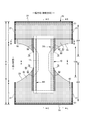
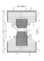
- FIG. 1 is a plan view of the main part of the exterior body
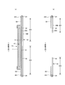
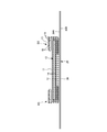
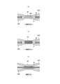
- FIG. 2 is a cross-sectional view taken along the line AA in FIG. FIG.
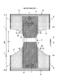
- FIG. 3 is a cross-sectional view taken along the line BB in FIG. It is a top view which shows only the principal part of the underpants type disposable diaper of a full expansion
- FIG. 1 to 7 show a pants-type disposable diaper.
- This pants-type disposable diaper (hereinafter also simply referred to as a diaper) has an exterior body 20 that forms a front body F and a back body B, and an interior body 10 that is fixed to and integrated with the inner surface of the exterior body 20.
- the interior body 10 is formed by interposing an absorbent body 13 between a liquid-permeable top sheet 11 and a liquid-impermeable back sheet 12.
- a joining means such as a hot melt adhesive (shaded portion 10B in FIG. 7)
- the interior body 10 and the exterior body 20 are joined. Is folded at the center in the front-rear direction (longitudinal direction), which is the boundary between the front body F and the back body B, and both side portions thereof are joined to each other by heat welding or hot melt adhesive to form the side seal portion 21.
- a pants-type disposable diaper having a waist opening and a pair of left and right leg openings is formed.
- the interior body 10 has an absorbent body 13 interposed between a liquid-permeable top sheet 11 made of nonwoven fabric or the like and a liquid-impermeable back side sheet 12 made of polyethylene or the like.
- the excretory fluid that has permeated through the top sheet 11 is absorbed and retained.
- the planar shape of the interior body 10 is not particularly limited, but is generally rectangular as illustrated.
- a porous or non-porous nonwoven fabric or a porous plastic sheet is preferably used as the liquid-permeable surface sheet 11 covering the surface side (skin contact surface side) of the absorbent body 13.
- the material fibers constituting the nonwoven fabric can be made of synthetic fibers such as polyethylene or polypropylene, synthetic fibers such as polyester or polyamide, recycled fibers such as rayon or cupra, natural fibers such as cotton, and the spunlace method.
- a nonwoven fabric obtained by an appropriate processing method such as a spun bond method, a thermal bond method, a melt blown method, or a needle punch method can be used. Among these processing methods, the spunlace method is excellent in terms of flexibility and drapeability, and the thermal bond method is excellent in terms of being bulky and soft.
- liquid permeable surface sheet 11 When a large number of through holes are formed in the liquid permeable surface sheet 11, urine and the like are quickly absorbed, and the dry touch property is excellent.
- the liquid permeable top sheet 11 is wound around the side edge of the absorber 13 and extends to the back side of the absorber 13.
- liquid-impermeable back sheet 12 that covers the back surface side (non-skin contact surface side) of the absorbent body 13 a liquid-impermeable plastic sheet such as polyethylene or polypropylene is used. Those having wettability are preferably used.
- This water-impervious and moisture-permeable sheet is a microporous sheet obtained by, for example, melt-kneading an inorganic filler in an olefin resin such as polyethylene or polypropylene to form a sheet, and then stretching in a uniaxial or biaxial direction. is there.
- Absorbent body 13 is a known one, for example, a pulp fiber stack, a filament aggregate such as cellulose acetate, or a non-woven fabric, mixed with a superabsorbent polymer as necessary, fixed, etc. Can be used.
- the absorbent body 13 can be packaged with a wrapping sheet 14 having liquid permeability and liquid retention, such as crepe paper, if necessary, for holding the shape and polymer.
- the shape of the absorber 13 is formed in a substantially hourglass shape having a narrowed portion 13N having a narrower width than the front and rear sides in the crotch portion, but may be an appropriate shape such as a rectangular shape.
- the size of the constricted portion 13N can be determined as appropriate, but the length in the front-rear direction of the constricted portion 13N can be about 20 to 50% of the total length of the diaper, and the width of the narrowest portion is 40% of the total width of the absorber 13. It can be about 60%.
- the planar shape of the interior body 10 is substantially rectangular, the remainder of the interior body 10 that does not have the absorber 13 in the portion corresponding to the constricted portion 13N of the absorber 13 A part is formed.
- the three-dimensional gather BS that fits around the legs is formed on both sides of the interior body 10.
- the three-dimensional gather BS includes a fixed portion fixed to a side portion on the back surface of the interior body, and a side portion on the surface of the interior body from the fixed portion to the side of the interior body.
- the body part that extends to the front, the front and rear ends of the body part in a lying state, and the lying part that is fixed to the side of the surface of the interior body, and the freedom part that is formed with this lying part being unfixed
- the part is formed of a gathered nonwoven fabric 15 that is turned into a double sheet by folding.
- an elongated gather elastic member 16 is disposed at the free end of the free portion.
- the gather elastic member 16 is for forming a three-dimensional gather BS by raising a free part by elastic stretching force as shown by a two-dot chain line in FIG. 5 in the product state.
- the liquid-impermeable back sheet 12 is folded back on the both sides in the width direction of the absorber 13 together with the liquid-permeable surface sheet 11.
- the liquid-impermeable back side sheet 12 it is desirable to use an opaque sheet so that brown such as defecation and urine does not appear.
- a plastic film and a pigment and filler such as calcium carbonate, titanium oxide, zinc oxide, white carbon, clay, talc and barium sulfate are preferably used.
- the gather elastic member 16 materials such as styrene rubber, olefin rubber, urethane rubber, ester rubber, polyurethane, polyethylene, polystyrene, styrene butadiene, silicon, polyester and the like that are usually used can be used. In order to make it difficult to see from the outside, it is preferable that the thickness is 925 dtex or less, the tension is 150 to 350%, and the interval is 7.0 mm or less.
- the gathered elastic member 16 may be a tape-like member having a certain width in addition to the thread-like shape shown in the figure.
- the material fiber constituting the gathered nonwoven fabric 15 is made of synthetic fibers such as polyethylene or polypropylene, synthetic fibers such as polyester or amide, recycled fibers such as rayon or cupra, and cotton.
- Non-woven fabric obtained by an appropriate processing method such as a spunbond method, a thermal bond method, a melt blown method, a needle punch method, etc. can be used. It is preferable to use a nonwoven fabric that suppresses the basis weight and has excellent air permeability.
- the gathered nonwoven fabric 15 in order to prevent the transmission of urine and the like, to prevent fogging, and to enhance the touch to the skin (dry feeling), silicon-based, paraffin metal-based, alkylchromic croid-based water repellent, etc. It is desirable to use a water-repellent non-woven fabric coated with.
- the exterior body 20 is provided with an elastic film 30 and an elongated elastic member 24 along the width direction between the first sheet layer 20A and the second sheet layer 20B. Elasticity in the width direction is given.
- the planar shape of the exterior body 20 has a pseudo hourglass shape as a whole due to concave leg-around lines 29 formed to form leg openings on both sides of the middle.
- the exterior body 20 may be divided into two parts in the front-rear direction so that both are separated in the front-rear direction at the crotch part.
- the waist portion 23 is located on the waist portion 23 in the waist region T defined as the longitudinal range of the side seal portion 21 where the front body F and the back body B are joined.
- An elastic member 24 is provided.
- the waist elastic member 24 in the illustrated form is an elongated elastic member such as a plurality of rubber bands arranged at intervals in the vertical direction, and gives a stretching force so as to tighten around the body torso.
- the waist elastic members 24 are not arranged substantially as a single bundle with a close spacing, but with a spacing of about 3 to 8 mm so as to form a predetermined stretch zone, preferably three or more, preferably Five or more are arranged.
- the elongation rate at the time of fixing the waist elastic member 24 can be determined as appropriate, but can be about 230 to 320% for a normal adult.
- the waist elastic member 24 one or a plurality of belt-like elastic members can be used.
- the rubber elastic member 24 is made of rubber thread. However, for example, a tape-like elastic member may be used. Alternatively, an elastic film described later may be extended to the waist 23. .
- the waist elastic member 24 in the illustrated form is sandwiched between folded portions 20C formed by folding the constituent material of the second sheet layer 20B to the inner surface side at the waist opening edge. You may pinch
- the constituent material of the first sheet layer 20A and the second sheet layer 20B can be used without particular limitation as long as it is a sheet, but it is preferable to use a nonwoven fabric from the viewpoint of air permeability and flexibility.
- the nonwoven fabric is not particularly limited as to what the raw fiber is.
- synthetic fibers such as olefins such as polyethylene and polypropylene, polyesters and polyamides, recycled fibers such as rayon and cupra, natural fibers such as cotton, and mixed fibers and composite fibers using two or more of them. Etc. can be illustrated.
- the nonwoven fabric may be manufactured by any processing.
- the processing method examples include known methods such as a spunlace method, a spunbond method, a thermal bond method, a melt blown method, a needle punch method, an air through method, and a point bond method.
- the basis weight is preferably about 10 to 25 g / m 2 .
- the first sheet layer 20A and the second sheet layer 20B may be a pair of layers in which a part or all of the first sheet layer is folded and faced.
- the elastic film stretchable structure 20 ⁇ / b> X is provided in the waist region T of the front body F, the waist region T of the back body B, and the intermediate region L between them, as shown in FIG. 2. Is formed. That is, in the stretchable structure 20X of the exterior body 20, in the width direction intermediate portion including the portion overlapping the absorber 13 (a part or all of the overlapping portion may be included, and it is desirable to include substantially the entire interior body fixing portion 10B). A non-stretchable region 70 is provided, and portions up to the side seal portions 21 on both sides in the width direction are the stretchable regions 80. As shown in FIG.
- the elastic film 30 is laminated between the first sheet layer 20A and the second sheet layer 20B over the entire stretchable region 80 and non-stretchable region 70, and the elastic film.
- the first sheet layer 20A and the second sheet layer 20B are elastic films with a large number of joints 40 arranged at intervals in the expansion / contraction direction and the direction orthogonal thereto. They are joined through a through hole 31 formed in 30.
- an elastic film stretchable structure 20X basically, the higher the area ratio of the joint portion 40, the fewer the portions of the first sheet layer 20A and the second sheet layer 20B that are contracted by the elastic film 30. Accordingly, the area ratio of the opening of the through hole 31 in the elastic film 30 is also increased, and the proportion of the stretched direction continuous portion of the elastic film 30 in the direction orthogonal to the stretched direction is reduced. There is a tendency that the elastic film 30 tends to tear as the shrinkage force generated sometimes decreases.
- the area ratio of the joint portion 40 is higher than that of the stretchable region 80, so that the elastic limit elongation in the stretch direction is 130% or less (preferably 120% or less, more preferably
- the elastic limit elongation in the stretchable direction is 200% or more (preferably 265 to 295%).
- the “elastic limit elongation” means the elongation at the elastic limit (in other words, the state where the first sheet layer and the second sheet layer are completely expanded), and the length at the elastic limit is the natural length of 100. The percentage is expressed as%.
- the first sheet layer 20A and the second sheet layer 20B between the joints swell in a direction away from each other, and the stretch direction
- a shrinking eyelid 25 extending in a direction intersecting with is formed, and as shown in FIG. 3C, the shrinking eyelid 25 is stretched but remains even in a mounted state that extends to some extent in the width direction.
- the first sheet layer 20A and the second sheet layer 20B are not joined to the elastic film 30 except at least between the first sheet layer 20A and the second sheet layer 20B in the joint portion 40. As can be seen from FIG. 3C assuming the mounted state and FIGS.
- the portion swelled in a streak shape between the joints 40 or extremely small.
- the stretchability is substantially killed.
- region 80 is joined part 40 rather than the main expansion-contraction part 81 except the said edge part.
- the buffer expansion / contraction portion 82 has a low area ratio. It is considered that the following changes occur during expansion due to the buffer expansion / contraction portion. In other words, considering that the natural stretched state is gradually extended from the natural length state, the buffer stretchable portion 82 and the main stretchable portion 81 both extend, but the buffer stretchable portion 82 is elastic before the main stretchable portion 81. It extends to the limit and becomes the fully expanded state (the state shown in FIG.
- the main stretchable portion 81 is in the incompletely deployed state (the state shown in FIG. 3C), and then the main stretchable portion 81.
- the buffer expansion / contraction portion 82 is stretched, but its elastic limit elongation is small, and therefore the tension applied to the boundary between the buffer expansion / contraction portion 82 and the non-stretch region 70 in the elastic film 30 is also small. Rupture of the elastic film 30 at the boundary between 82 and the non-stretchable region 70 is less likely to occur.
- the tension applied to the boundary between the buffer stretchable portion 82 and the non-stretchable region 70 in the elastic film 30 does not exceed the elastic limit elongation of the first step, so that it is the same as the first step.
- the elastic film 30 is less likely to break at the boundary between the buffer stretchable portion 82 and the non-stretchable region 70.
- the buffer expansion / contraction portion 82 is determined by the tensile elongation in the expansion / contraction direction of the elastic film 30 having the same width as the interval between the through holes 31 of the elastic film 30 in the direction orthogonal to the expansion / contraction direction in the non-expandable region 70.
- the elastic limit elongation is small, it is preferable because the elastic film 30 can be reliably prevented from being broken at the boundary between the stretchable region 80 and the non-stretchable region 70.
- each joint 40 may be determined as appropriate, but if it is too large, the effect of the hardness of the joint 40 on the feel will increase, and if it is too small, the joint area will be small and the materials will not be sufficiently bonded together. Therefore, in general, the area of each joint 40 is preferably about 0.14 to 3.5 mm 2 .
- the area of the opening of each through hole 31 may be equal to or larger than the joint because the joint is formed through the through hole 31, but is preferably about 1 to 1.5 times the area of the joint. .
- each joint 40 in each region are as follows in a normal case.
- Non-stretchable region 70 Area of the joint 40: 0.14 to 3.5 mm 2 (particularly 0.25 to 1.0 mm 2 ) Area ratio of the joint 40: 16 to 45% (especially 25 to 45%)
- Mainn stretchable part 81 Area of the joint 40: 0.14 to 3.5 mm 2 (particularly 0.14 to 1.0 mm 2 ) Area ratio of the joint 40: 1.8 to 19.1% (particularly 1.8 to 10.6%)
- Buffer expansion / contraction part 82 Area of the joint 40: 0.14 to 3.5 mm 2 (particularly 0.25 to 1.0 mm 2 ) Area ratio of the joint 40: 8 to 22.5% (especially 12.5 to 22.5%)
- the area of the joint 40 can be the same in two or more of the non-stretchable region 70, the main stretchable portion 81 and the buffer stretchable portion 82, and can be different in all locations.
- the number of joints 40 per unit area may be the same at two or more of the non-stretchable region 70, the main stretchable portion 81, and the buffer stretchable portion 82, and may be different at all locations.
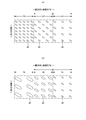
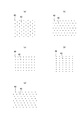
- the plane arrangement of the joints 40 and the through-holes 31 can be determined as appropriate, but a plane arrangement that is regularly repeated is preferable, such as an oblique lattice shape as shown in FIG. 20 (a), or as shown in FIG. 20 (b). Hexagonal lattice shape (these are also called staggered shapes), a square lattice shape as shown in FIG. 20 (c), a rectangular lattice shape as shown in FIG. 20 (d), and a parallel shape as shown in FIG. 20 (e). Body lattice (in the form shown in the figure, two groups are provided so that a large number of groups of parallel diagonal rows intersect each other), etc.
- the group of joints 40 (in which these are inclined at an angle of less than 90 degrees with respect to the expansion / contraction direction)
- group of joints 40 (group unit arrangement may be regular or irregular, and may be a pattern, a character shape, etc.) shall be regularly repeated. You can also.
- the arrangement form of the joint portion 40 and the through-hole 31 may be the same or different in the main stretchable portion 81, the buffer stretchable portion 82, and the non-stretchable region 70.
- a non-stretchable region 70 in which the joint portion 40 is arranged in a display 71 shape or the like can be provided in the expansion / contraction area
- a buffer expansion-contraction part can be provided in the expansion / contraction area
- the display 71 may be a display known in the field of absorbent articles, for example, a decorative pattern (including a one-point picture or character), a function display such as a method of use or assistance, and a size, or a manufacturer or It can be a mark display of product name, characteristic function, etc.
- a flower pattern display 71 which is a plant pattern is added, but it is needless to say that various patterns such as an abstract pattern, an animal pattern, and a natural phenomenon pattern can be used.
- the elastic film 30 is not particularly limited, and can be used without particular limitation as long as it is a resin film having its own elasticity.
- a styrene-based elastomer, an olefin-based elastomer, a polyester-based elastomer, a polyamide-based elastomer, and a polyurethane-based film can be used.
- a product obtained by processing one or two or more blends of thermoplastic elastomers such as elastomers into a film by extrusion molding such as a T-die method or an inflation method can be used.
- the elastic film 30 the thing in which many holes and slits were formed for ventilation other than a non-porous thing can also be used.
- the tensile strength in the stretching direction is 8 to 25 N / 35 mm
- the tensile strength in the direction perpendicular to the stretching direction is 5 to 20 N / 35 mm
- the tensile elongation in the stretching direction is 450 to 1050%
- the direction perpendicular to the stretching direction is preferable.
- the tensile strength and tensile elongation were determined according to JIS K7127 except that a tensile tester (for example, AOUTGRAPHAGS-G100N manufactured by SHIMADZU) was used and the test piece was a rectangular shape having a width of 35 mm and a length of 80 mm.
- a tensile tester for example, AOUTGRAPHAGS-G100N manufactured by SHIMADZU
- the thickness of the elastic film 30 is not particularly limited, but is preferably about 20 to 40 ⁇ m.
- the basis weight of the elastic film 30 is not particularly limited, but is preferably about 30 to 45 g / m 2 , particularly preferably about 30 to 35 g / m 2 .
- the joining of the first sheet layer 20A and the second sheet layer 20B in the joining portion 40 may be performed by a hot melt adhesive, but is preferably performed by a joining means by material welding such as heat sealing or ultrasonic sealing. preferable.
- a joining means by material welding such as heat sealing or ultrasonic sealing.
- the through hole of the elastic film is formed by extrusion, and the first sheet layer and the second sheet layer are directly fused at the position of the through hole.
- the peel strength is low, and there is a risk of peeling when a strong force is applied.
- the elastic film 30 remains between the 1st sheet layer 20A and the 2nd sheet layer 20B.
- joining of the 1st sheet layer 20A and the 2nd sheet layer 20B in the junction part 40 is at least 1st sheet layer 20A and
- formed by 30 m of the melt-solidified material of the elastic film 30 covering the 2nd sheet layer 20B is preferable.
- the peel strength becomes high, so that both high air permeability and high peel strength can be achieved.
- such a joining structure is formed by stretching the elastic film 30 between the first sheet layer 20 ⁇ / b> A and the second sheet layer 20 ⁇ / b> B with a substantially uniform elongation rate in a direction orthogonal to the stretching direction.
- the elastic film 30 is melted at a large number of locations to form the through-holes 31 by being welded with a predetermined pattern of the joining portions 40 while being stretched and sandwiched between the elastic films 30 and at least the elastic film at the positions of the through-holes 31. It can be manufactured simply and efficiently using a technique of joining the first sheet layer 20A and the second sheet layer 20B by solidifying the melt of 30.
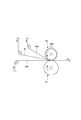
- FIG. 15 shows an example using a heat seal device, which is opposed to a seal roll 60 having a large number of pressurizing convex portions 60p arranged in the pattern of the joint portion 40 on the outer peripheral surface.
- the elastic film 30 is melted to form the through-hole 31 only at the portion pressed in the thickness direction between the pressure convex portion 60p and the outer peripheral surface of the anvil roll 61, and at least the elastic film is located at the position of the through-hole 31. While the first sheet layer 20A and the second sheet layer 20B are joined by solidifying the melt of 30, the elastic film 30 is melted in a desired pattern to form the through holes 31. As long as the first sheet layer 20A and the second sheet layer 20B can be joined by solidifying the melt of the elastic film 30 at the position of the through hole 31, other devices such as an ultrasonic seal can be used. .
- the relationship between the melting point of the elastic film 30, the melting points of the first sheet layer 20A and the second sheet layer 20B, and the level of the processing temperature at the welding position can be determined as appropriate, but the first sheet layer 20A and the second sheet layer 20B
- the melting point is set to be equal to or lower than the melting point of the elastic film 30, and the first sheet layer 20 ⁇ / b> A and the second sheet layer 20 ⁇ / b> B and the entire elastic film 30 are melted and mixed at the welding position, and the joining portion 40 is formed.
- the melting points of the first sheet layer 20A and the second sheet layer 20B are higher than the melting point of the elastic film 30, and the elastic film 30 is melted at the welding location, and part or all of the first sheet layer 20A and the second sheet layer 20B are It is preferable not to melt. That is, in the latter case, the first sheet layer 20A and the second sheet layer that are continuous from the periphery of the joint portion 40, as can be seen from FIGS. 20B fibers 20f remain, and the first sheet layer 20A and the second sheet layer 20B are joined by the melt-solidified product 30m of the elastic film 30 that has permeated and solidified the first sheet layer 20A and the second sheet layer 20B.
- the surrounding part (including not only the sheath in the composite fiber but also the part on the surface side of the single component fiber) melts, and some of the fibers do not melt at all, but the remaining fibers all melt or the core remains However, the surrounding part includes a molten form.
- the elastic film 30 preferably has a melting point of about 80 to 145 ° C., and the first sheet layer 20A and the second sheet layer 20B have melting points of about 85 to 190 ° C., particularly about 150 to 190 ° C.
- the difference between the melting point of the first sheet layer 20A and the second sheet layer 20B and the melting point of the elastic film 30 is preferably about 60 to 80 ° C.
- the shape of the through hole 31 in the natural length state is long in one direction, and its longitudinal direction and the width direction of the diaper.
- the inclination angle ⁇ determined as the intersection angle on the center side in the width direction is an inclination shape with an angle of 25 to 35 degrees.
- the illustrated example shows only the inclined shape of the through-hole 31 of the front body F, it goes without saying that the rear body B can also have the same inclined shape of the through-hole 31 instead of or together with this.
- the shape of the through-hole 31 in the natural length state is not particularly limited as long as it is long in one direction of the inclination angle ⁇ , but is a polygon such as an ellipse or a rectangle (including linear and rounded ones), a cloud shape Or any other shape.
- the shape of each joint 40 may be different from the through hole 31 such as a perfect circle, a star, or a regular polygon, but is preferably the same shape as the through hole 31.
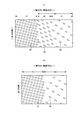
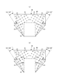
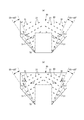
- the direction of the force when the stretchable region 80 is strongly extended obliquely upward due to the crotch portion being caught by a heel, a toe, or a knee is shown in FIGS. 18 and 19.
- the crossing angle outside the width direction with respect to the width direction is about 55 to 65 degrees.
- this angle is a flat state in which the front body F and the back body B are overlapped with each other in a direction connecting the side edge of the crotch portion and the end of the side seal portion 21 on the waist side. The angle is determined because most of the angles are within this range.
- the through holes 31 having an inclined shape that is long in the direction orthogonal to the direction in which the force is applied as described above have the same area and arrangement of the through holes 31 as compared to the case of a true circle or a square.
- each through hole 31 of the elastic film 30 is closest to a range of 55 to 65 degrees with a central angle of 0 degree in the width direction outside the through hole 31 as a center.
- An elastic film having no other through-holes 31 in the illustrated arrangement, the interval 31d is longer than the interval 31e), that is, by preventing the through-holes 31 from being arranged at a short distance in the direction in which a strong force is applied. 30 can be more difficult to break.
- an attachment method in which the side seal portion 21 is grasped and pulled up is common, and the direction of the force applied to the stretchable region 80 at the time of such attachment is indicated by a two-dot chain line arrow in FIG.
- the angle increases toward the crotch side.
- the inclination angle ⁇ of a large number of through holes 31 provided in the stretchable region 80 is the same as shown in FIG. If the inclined angles ⁇ 1 and ⁇ 2 of the large number of through-holes 31 are formed so as to decrease continuously or stepwise toward the crotch side, the elastic film 30 is more difficult to break.
- the large number of through holes 31 provided in the stretchable region 80 have each through hole 31 and the outer side in the width direction as 0 degrees with the through hole 31 as the center. If the shortest distance 31d with the other through hole 31 located in the range of 55 to 65 degrees in the central angle is formed so as to increase continuously or stepwise toward the crotch side, that is, the direction of the force It is preferable that the shortest distance 31d between the through holes 31 is increased continuously or stepwise in accordance with this because the elastic film 30 is more difficult to break.
- the illustrated example is an example in which the elastic film stretchable structure 20X is applied to a stretchable structure other than the waist portion 23 of the exterior body 20.
- the elastic body stretchable structure 20X may be applied including the waist portion 23 or the waist region T and the back body of the front body F.
- Appropriate changes can be made, such as a configuration in which the elastic film stretchable structure 20X is not provided in the intermediate region L between the waistline region T of B.
- the stretchable structure 20X described above is not limited to pants-type disposable diapers, but also to other stretchable parts such as three-dimensional gathers, flat gathers, etc. that are widely used around the waist of a tape-type disposable diaper, fastening tape, and absorbent articles in general. Can also be applied.
- this embodiment has the non-expandable area
- the expansion / contraction direction is the width direction, but it is also possible to use the front-rear direction or both the width direction and the front-rear direction.
- the front presser sheet 50 extends over the entire width direction from the inner surface of the folded portion 20C of the waist side end of the front body F to the position overlapping the front end of the interior body 10.
- the rear pressing sheet 60 extends over the entire width direction from the inner surface of the folded portion 20C of the waist side end portion to the position overlapping the rear end portion of the interior body 10 in the inner surface of the back body B.
- the folded portion 20C formed by folding the exterior body 20 on the inner surface of the diaper can be extended to a portion overlapping the interior body 10 to form a portion equivalent to the above-described pressing sheets 50 and 60.
- Elongation rate means a value when the natural length is 100%.
- Weight is measured as follows. After the sample or test piece has been pre-dried, it is left in a test room or apparatus in a standard state (test location is temperature 20 ⁇ 5 ° C., relative humidity 65% or less) to obtain a constant weight. Pre-drying refers to making a sample or test piece constant in an environment where the relative humidity is 10 to 25% and the temperature does not exceed 50 ° C. In addition, it is not necessary to perform preliminary drying about the fiber whose official moisture content is 0.0%.
- a sample with a size of 200 mm ⁇ 250 mm ( ⁇ 2 mm) is cut out from the test piece in a constant weight using a rice-basis plate (200 mm ⁇ 250 mm, ⁇ 2 mm). Measure the weight of the sample, multiply it by 20, calculate the weight per square meter, and use it as the basis weight. “Thickness” is automatically measured using an automatic thickness measuring instrument (KES-G5 handy compression measurement program) under the conditions of load: 10 gf / cm 2 and pressure area: 2 cm 2 . ⁇ If there is no description about the environmental conditions in the test and measurement, the test and measurement shall be performed in a test room or equipment in the standard condition (test location is temperature 20 ⁇ 5 °C, relative humidity 65% or less). .
- the present invention can be used for a pants-type disposable diaper as in the above example.
- B Rear body, F ... Front body, T ... Trunk circumference region, L ... Intermediate region, 10 ... Interior body, 11 ... Liquid permeable top sheet, 12 ... Liquid impervious back side sheet, 13 ... Absorber, 13N DESCRIPTION OF SYMBOLS ... Constricted part, 14 ... Packaging sheet, 15 ... Gathered nonwoven fabric, 16 ... Gather elastic member, 20 ... Exterior body, 20A ... First sheet layer, 20B ... Second sheet layer, 20C ... Folded part, 20X ... Stretch structure, 21 DESCRIPTION OF SYMBOLS ... Side seal part, 24 ... Waist part elastic member, 25 ... Shrinkage collar, 29 ... Leg circumference line, 30 ...
- Elastic film 31 ... Through-hole, 40 ... Joint part, 70 ... Non-stretchable area, 71 ... Display, 80 ... Expansion / contraction area, 81 ... main expansion / contraction part, 82 ... buffer expansion / contraction part, 31d ... shortest interval.
Landscapes
- Health & Medical Sciences (AREA)
- Epidemiology (AREA)
- Engineering & Computer Science (AREA)
- Biomedical Technology (AREA)
- Heart & Thoracic Surgery (AREA)
- Vascular Medicine (AREA)
- Life Sciences & Earth Sciences (AREA)
- Animal Behavior & Ethology (AREA)
- General Health & Medical Sciences (AREA)
- Public Health (AREA)
- Veterinary Medicine (AREA)
- Absorbent Articles And Supports Therefor (AREA)
Abstract
Le problème posé est d'empêcher la rupture d'un film élastique lorsqu'on met une couche-culotte d'apprentissage jetable. Le problème est résolu si l'on prévoit une zone extensible (80) qui peut s'étirer élastiquement dans le sens de la largeur sur au moins l'un ou l'autre côté dans le sens de la largeur d'un corps externe (20). Dans la zone extensible (80), un film élastique (30) est stratifié entre une première couche en feuille (20A) comprenant un tissu non tissé et une seconde couche en feuille (20B) comprenant un tissu non tissé et, le film élastique (30) étendu dans la direction d'étirement, la première couche en feuille (20A) et la seconde couche en feuille (20B) sont assemblées par des trous de passage (31) formés dans le film élastique (30) au niveau de nombreuses sections d'assemblage (40) espacées à la fois dans la direction de l'étirement et dans la direction orthogonale à celui-ci. La forme des trous de passage (31) dans leur longueur naturelle est une configuration inclinée qui est longue dans une direction et présente un angle d'inclinaison thêta de 25 à 35 degrés. L'angle d'inclinaison thêta est l'un des angles d'intersection entre le sens longitudinal des trous de passage (31) et la largeur de la couche-culotte, et est l'angle d'intersection situé vers le centre dans le sens de la largeur.
Applications Claiming Priority (2)
| Application Number | Priority Date | Filing Date | Title |
|---|---|---|---|
| JP2015068067A JP6082418B2 (ja) | 2015-03-30 | 2015-03-30 | パンツタイプ使い捨ておむつ |
| JP2015-068067 | 2015-03-30 |
Publications (1)
| Publication Number | Publication Date |
|---|---|
| WO2016158751A1 true WO2016158751A1 (fr) | 2016-10-06 |
Family
ID=57004669
Family Applications (1)
| Application Number | Title | Priority Date | Filing Date |
|---|---|---|---|
| PCT/JP2016/059625 Ceased WO2016158751A1 (fr) | 2015-03-30 | 2016-03-25 | Couche-culotte d'apprentissage jetable |
Country Status (2)
| Country | Link |
|---|---|
| JP (1) | JP6082418B2 (fr) |
| WO (1) | WO2016158751A1 (fr) |
Cited By (2)
| Publication number | Priority date | Publication date | Assignee | Title |
|---|---|---|---|---|
| US20200214904A1 (en) * | 2017-09-27 | 2020-07-09 | Daio Paper Corporation | Elastic member and disposable wearing article including elastic member |
| EP3689311B1 (fr) | 2017-09-27 | 2023-11-08 | Daio Paper Corporation | Élément élastique, article vestimentaire jetable utilisant cet élément élastique, et procédé de production d'élément élastique |
Families Citing this family (3)
| Publication number | Priority date | Publication date | Assignee | Title |
|---|---|---|---|---|
| JP6492152B1 (ja) * | 2017-11-24 | 2019-03-27 | 大王製紙株式会社 | 伸縮部材及びこの伸縮部材を有する使い捨て着用物品 |
| WO2019065572A1 (fr) * | 2017-09-27 | 2019-04-04 | 大王製紙株式会社 | Élément élastique et article vestimentaire jetable utilisant cet élément élastique |
| DE102018125746A1 (de) * | 2018-10-17 | 2020-04-23 | Mondi Ag | Elastische Folie sowie Verfahren zur Herstellung eines elastischen Schichtmaterials |
Citations (3)
| Publication number | Priority date | Publication date | Assignee | Title |
|---|---|---|---|---|
| JP2004532758A (ja) * | 2001-06-21 | 2004-10-28 | ザ プロクター アンド ギャンブル カンパニー | 弾性のある積層ウェブ |
| JP2006198132A (ja) * | 2005-01-20 | 2006-08-03 | Kao Corp | 吸収性物品 |
| JP2008260131A (ja) * | 2007-04-10 | 2008-10-30 | Zuiko Corp | 積層伸縮シートの製造方法 |
-
2015
- 2015-03-30 JP JP2015068067A patent/JP6082418B2/ja active Active
-
2016
- 2016-03-25 WO PCT/JP2016/059625 patent/WO2016158751A1/fr not_active Ceased
Patent Citations (3)
| Publication number | Priority date | Publication date | Assignee | Title |
|---|---|---|---|---|
| JP2004532758A (ja) * | 2001-06-21 | 2004-10-28 | ザ プロクター アンド ギャンブル カンパニー | 弾性のある積層ウェブ |
| JP2006198132A (ja) * | 2005-01-20 | 2006-08-03 | Kao Corp | 吸収性物品 |
| JP2008260131A (ja) * | 2007-04-10 | 2008-10-30 | Zuiko Corp | 積層伸縮シートの製造方法 |
Cited By (3)
| Publication number | Priority date | Publication date | Assignee | Title |
|---|---|---|---|---|
| US20200214904A1 (en) * | 2017-09-27 | 2020-07-09 | Daio Paper Corporation | Elastic member and disposable wearing article including elastic member |
| US11529266B2 (en) * | 2017-09-27 | 2022-12-20 | Daio Paper Corporation | Elastic member and disposable wearing article including elastic member |
| EP3689311B1 (fr) | 2017-09-27 | 2023-11-08 | Daio Paper Corporation | Élément élastique, article vestimentaire jetable utilisant cet élément élastique, et procédé de production d'élément élastique |
Also Published As
| Publication number | Publication date |
|---|---|
| JP2016187385A (ja) | 2016-11-04 |
| JP6082418B2 (ja) | 2017-02-15 |
Similar Documents
| Publication | Publication Date | Title |
|---|---|---|
| JP5980355B2 (ja) | 吸収性物品の伸縮構造、及びこれを用いたパンツタイプ使い捨ておむつ | |
| JP6049222B2 (ja) | 吸収性物品及びその製造方法 | |
| JP6636855B2 (ja) | 吸収性物品 | |
| JP5967736B1 (ja) | 吸収性物品 | |
| WO2016121976A1 (fr) | Article absorbant et procédé de production associé | |
| JP5980367B1 (ja) | 吸収性物品の製造方法 | |
| JP2016193199A5 (fr) | ||
| JP5964477B1 (ja) | 吸収性物品 | |
| JP5999790B1 (ja) | パンツタイプ使い捨ておむつ | |
| JP6331199B2 (ja) | 吸収性物品 | |
| JP6049228B1 (ja) | 吸収性物品 | |
| WO2016121979A1 (fr) | Article absorbant | |
| WO2016159095A1 (fr) | Couche jetable de type sous-vêtement | |
| JP6082418B2 (ja) | パンツタイプ使い捨ておむつ | |
| JP5918877B1 (ja) | 吸収性物品及びその製造方法 | |
| JP6709550B2 (ja) | 吸収性物品及びその製造方法 | |
| JP2016189826A5 (fr) | ||
| JP6739962B2 (ja) | パンツタイプ使い捨ておむつ | |
| JP6447924B2 (ja) | 使い捨ておむつ | |
| WO2016121978A1 (fr) | Article absorbant et procédé de production associé | |
| JP6276215B2 (ja) | パンツタイプ使い捨ておむつ | |
| JP2017064230A5 (fr) | ||
| JP5918876B1 (ja) | パンツタイプ使い捨ておむつ | |
| JP5967735B1 (ja) | パンツタイプ使い捨ておむつ | |
| JP2016187387A5 (fr) |
Legal Events
| Date | Code | Title | Description |
|---|---|---|---|
| 121 | Ep: the epo has been informed by wipo that ep was designated in this application |
Ref document number: 16772632 Country of ref document: EP Kind code of ref document: A1 |
|
| NENP | Non-entry into the national phase |
Ref country code: DE |
|
| 122 | Ep: pct application non-entry in european phase |
Ref document number: 16772632 Country of ref document: EP Kind code of ref document: A1 |