WO2016159143A1 - Dispositif électronique et produit de programme informatique - Google Patents
Dispositif électronique et produit de programme informatique Download PDFInfo
- Publication number
- WO2016159143A1 WO2016159143A1 PCT/JP2016/060496 JP2016060496W WO2016159143A1 WO 2016159143 A1 WO2016159143 A1 WO 2016159143A1 JP 2016060496 W JP2016060496 W JP 2016060496W WO 2016159143 A1 WO2016159143 A1 WO 2016159143A1
- Authority
- WO
- WIPO (PCT)
- Prior art keywords
- image
- imaging
- unit
- electronic device
- imaging condition
- Prior art date
- Legal status (The legal status is an assumption and is not a legal conclusion. Google has not performed a legal analysis and makes no representation as to the accuracy of the status listed.)
- Ceased
Links
Images








Classifications
-
- G—PHYSICS
- G03—PHOTOGRAPHY; CINEMATOGRAPHY; ANALOGOUS TECHNIQUES USING WAVES OTHER THAN OPTICAL WAVES; ELECTROGRAPHY; HOLOGRAPHY
- G03B—APPARATUS OR ARRANGEMENTS FOR TAKING PHOTOGRAPHS OR FOR PROJECTING OR VIEWING THEM; APPARATUS OR ARRANGEMENTS EMPLOYING ANALOGOUS TECHNIQUES USING WAVES OTHER THAN OPTICAL WAVES; ACCESSORIES THEREFOR
- G03B15/00—Special procedures for taking photographs; Apparatus therefor
-
- G—PHYSICS
- G03—PHOTOGRAPHY; CINEMATOGRAPHY; ANALOGOUS TECHNIQUES USING WAVES OTHER THAN OPTICAL WAVES; ELECTROGRAPHY; HOLOGRAPHY
- G03B—APPARATUS OR ARRANGEMENTS FOR TAKING PHOTOGRAPHS OR FOR PROJECTING OR VIEWING THEM; APPARATUS OR ARRANGEMENTS EMPLOYING ANALOGOUS TECHNIQUES USING WAVES OTHER THAN OPTICAL WAVES; ACCESSORIES THEREFOR
- G03B7/00—Control of exposure by setting shutters, diaphragms or filters, separately or conjointly
- G03B7/08—Control effected solely on the basis of the response, to the intensity of the light received by the camera, of a built-in light-sensitive device
- G03B7/091—Digital circuits
-
- G—PHYSICS
- G06—COMPUTING OR CALCULATING; COUNTING
- G06V—IMAGE OR VIDEO RECOGNITION OR UNDERSTANDING
- G06V10/00—Arrangements for image or video recognition or understanding
- G06V10/10—Image acquisition
-
- G—PHYSICS
- G06—COMPUTING OR CALCULATING; COUNTING
- G06V—IMAGE OR VIDEO RECOGNITION OR UNDERSTANDING
- G06V10/00—Arrangements for image or video recognition or understanding
- G06V10/40—Extraction of image or video features
- G06V10/50—Extraction of image or video features by performing operations within image blocks; by using histograms, e.g. histogram of oriented gradients [HoG]; by summing image-intensity values; Projection analysis
-
- G—PHYSICS
- G06—COMPUTING OR CALCULATING; COUNTING
- G06V—IMAGE OR VIDEO RECOGNITION OR UNDERSTANDING
- G06V10/00—Arrangements for image or video recognition or understanding
- G06V10/40—Extraction of image or video features
- G06V10/56—Extraction of image or video features relating to colour
-
- H—ELECTRICITY
- H04—ELECTRIC COMMUNICATION TECHNIQUE
- H04N—PICTORIAL COMMUNICATION, e.g. TELEVISION
- H04N23/00—Cameras or camera modules comprising electronic image sensors; Control thereof
- H04N23/60—Control of cameras or camera modules
-
- H—ELECTRICITY
- H04—ELECTRIC COMMUNICATION TECHNIQUE
- H04N—PICTORIAL COMMUNICATION, e.g. TELEVISION
- H04N23/00—Cameras or camera modules comprising electronic image sensors; Control thereof
- H04N23/60—Control of cameras or camera modules
- H04N23/62—Control of parameters via user interfaces
-
- H—ELECTRICITY
- H04—ELECTRIC COMMUNICATION TECHNIQUE
- H04N—PICTORIAL COMMUNICATION, e.g. TELEVISION
- H04N23/00—Cameras or camera modules comprising electronic image sensors; Control thereof
- H04N23/60—Control of cameras or camera modules
- H04N23/63—Control of cameras or camera modules by using electronic viewfinders
-
- H—ELECTRICITY
- H04—ELECTRIC COMMUNICATION TECHNIQUE
- H04N—PICTORIAL COMMUNICATION, e.g. TELEVISION
- H04N23/00—Cameras or camera modules comprising electronic image sensors; Control thereof
- H04N23/60—Control of cameras or camera modules
- H04N23/63—Control of cameras or camera modules by using electronic viewfinders
- H04N23/631—Graphical user interfaces [GUI] specially adapted for controlling image capture or setting capture parameters
- H04N23/632—Graphical user interfaces [GUI] specially adapted for controlling image capture or setting capture parameters for displaying or modifying preview images prior to image capturing, e.g. variety of image resolutions or capturing parameters
-
- H—ELECTRICITY
- H04—ELECTRIC COMMUNICATION TECHNIQUE
- H04N—PICTORIAL COMMUNICATION, e.g. TELEVISION
- H04N23/00—Cameras or camera modules comprising electronic image sensors; Control thereof
- H04N23/60—Control of cameras or camera modules
- H04N23/63—Control of cameras or camera modules by using electronic viewfinders
- H04N23/633—Control of cameras or camera modules by using electronic viewfinders for displaying additional information relating to control or operation of the camera
- H04N23/635—Region indicators; Field of view indicators
-
- H—ELECTRICITY
- H04—ELECTRIC COMMUNICATION TECHNIQUE
- H04N—PICTORIAL COMMUNICATION, e.g. TELEVISION
- H04N23/00—Cameras or camera modules comprising electronic image sensors; Control thereof
- H04N23/60—Control of cameras or camera modules
- H04N23/67—Focus control based on electronic image sensor signals
-
- H—ELECTRICITY
- H04—ELECTRIC COMMUNICATION TECHNIQUE
- H04N—PICTORIAL COMMUNICATION, e.g. TELEVISION
- H04N23/00—Cameras or camera modules comprising electronic image sensors; Control thereof
- H04N23/60—Control of cameras or camera modules
- H04N23/67—Focus control based on electronic image sensor signals
- H04N23/673—Focus control based on electronic image sensor signals based on contrast or high frequency components of image signals, e.g. hill climbing method
-
- H—ELECTRICITY
- H04—ELECTRIC COMMUNICATION TECHNIQUE
- H04N—PICTORIAL COMMUNICATION, e.g. TELEVISION
- H04N23/00—Cameras or camera modules comprising electronic image sensors; Control thereof
- H04N23/70—Circuitry for compensating brightness variation in the scene
- H04N23/71—Circuitry for evaluating the brightness variation
-
- H—ELECTRICITY
- H04—ELECTRIC COMMUNICATION TECHNIQUE
- H04N—PICTORIAL COMMUNICATION, e.g. TELEVISION
- H04N23/00—Cameras or camera modules comprising electronic image sensors; Control thereof
- H04N23/70—Circuitry for compensating brightness variation in the scene
- H04N23/72—Combination of two or more compensation controls
-
- H—ELECTRICITY
- H04—ELECTRIC COMMUNICATION TECHNIQUE
- H04N—PICTORIAL COMMUNICATION, e.g. TELEVISION
- H04N23/00—Cameras or camera modules comprising electronic image sensors; Control thereof
- H04N23/70—Circuitry for compensating brightness variation in the scene
- H04N23/73—Circuitry for compensating brightness variation in the scene by influencing the exposure time
-
- H—ELECTRICITY
- H04—ELECTRIC COMMUNICATION TECHNIQUE
- H04N—PICTORIAL COMMUNICATION, e.g. TELEVISION
- H04N23/00—Cameras or camera modules comprising electronic image sensors; Control thereof
- H04N23/70—Circuitry for compensating brightness variation in the scene
- H04N23/76—Circuitry for compensating brightness variation in the scene by influencing the image signals
-
- H—ELECTRICITY
- H04—ELECTRIC COMMUNICATION TECHNIQUE
- H04N—PICTORIAL COMMUNICATION, e.g. TELEVISION
- H04N25/00—Circuitry of solid-state image sensors [SSIS]; Control thereof
- H04N25/10—Circuitry of solid-state image sensors [SSIS]; Control thereof for transforming different wavelengths into image signals
- H04N25/11—Arrangement of colour filter arrays [CFA]; Filter mosaics
- H04N25/13—Arrangement of colour filter arrays [CFA]; Filter mosaics characterised by the spectral characteristics of the filter elements
- H04N25/134—Arrangement of colour filter arrays [CFA]; Filter mosaics characterised by the spectral characteristics of the filter elements based on three different wavelength filter elements
-
- H—ELECTRICITY
- H04—ELECTRIC COMMUNICATION TECHNIQUE
- H04N—PICTORIAL COMMUNICATION, e.g. TELEVISION
- H04N25/00—Circuitry of solid-state image sensors [SSIS]; Control thereof
- H04N25/50—Control of the SSIS exposure
- H04N25/53—Control of the integration time
- H04N25/533—Control of the integration time by using differing integration times for different sensor regions
-
- H—ELECTRICITY
- H04—ELECTRIC COMMUNICATION TECHNIQUE
- H04N—PICTORIAL COMMUNICATION, e.g. TELEVISION
- H04N25/00—Circuitry of solid-state image sensors [SSIS]; Control thereof
- H04N25/70—SSIS architectures; Circuits associated therewith
- H04N25/79—Arrangements of circuitry being divided between different or multiple substrates, chips or circuit boards, e.g. stacked image sensors
-
- H—ELECTRICITY
- H10—SEMICONDUCTOR DEVICES; ELECTRIC SOLID-STATE DEVICES NOT OTHERWISE PROVIDED FOR
- H10F—INORGANIC SEMICONDUCTOR DEVICES SENSITIVE TO INFRARED RADIATION, LIGHT, ELECTROMAGNETIC RADIATION OF SHORTER WAVELENGTH OR CORPUSCULAR RADIATION
- H10F39/00—Integrated devices, or assemblies of multiple devices, comprising at least one element covered by group H10F30/00, e.g. radiation detectors comprising photodiode arrays
- H10F39/10—Integrated devices
- H10F39/12—Image sensors
- H10F39/199—Back-illuminated image sensors
-
- H—ELECTRICITY
- H10—SEMICONDUCTOR DEVICES; ELECTRIC SOLID-STATE DEVICES NOT OTHERWISE PROVIDED FOR
- H10F—INORGANIC SEMICONDUCTOR DEVICES SENSITIVE TO INFRARED RADIATION, LIGHT, ELECTROMAGNETIC RADIATION OF SHORTER WAVELENGTH OR CORPUSCULAR RADIATION
- H10F39/00—Integrated devices, or assemblies of multiple devices, comprising at least one element covered by group H10F30/00, e.g. radiation detectors comprising photodiode arrays
- H10F39/80—Constructional details of image sensors
- H10F39/805—Coatings
- H10F39/8053—Colour filters
-
- H—ELECTRICITY
- H10—SEMICONDUCTOR DEVICES; ELECTRIC SOLID-STATE DEVICES NOT OTHERWISE PROVIDED FOR
- H10F—INORGANIC SEMICONDUCTOR DEVICES SENSITIVE TO INFRARED RADIATION, LIGHT, ELECTROMAGNETIC RADIATION OF SHORTER WAVELENGTH OR CORPUSCULAR RADIATION
- H10F39/00—Integrated devices, or assemblies of multiple devices, comprising at least one element covered by group H10F30/00, e.g. radiation detectors comprising photodiode arrays
- H10F39/80—Constructional details of image sensors
- H10F39/806—Optical elements or arrangements associated with the image sensors
- H10F39/8063—Microlenses
-
- G—PHYSICS
- G06—COMPUTING OR CALCULATING; COUNTING
- G06V—IMAGE OR VIDEO RECOGNITION OR UNDERSTANDING
- G06V10/00—Arrangements for image or video recognition or understanding
- G06V10/10—Image acquisition
- G06V10/12—Details of acquisition arrangements; Constructional details thereof
- G06V10/14—Optical characteristics of the device performing the acquisition or on the illumination arrangements
- G06V10/147—Details of sensors, e.g. sensor lenses
-
- H—ELECTRICITY
- H04—ELECTRIC COMMUNICATION TECHNIQUE
- H04N—PICTORIAL COMMUNICATION, e.g. TELEVISION
- H04N23/00—Cameras or camera modules comprising electronic image sensors; Control thereof
- H04N23/60—Control of cameras or camera modules
- H04N23/67—Focus control based on electronic image sensor signals
- H04N23/672—Focus control based on electronic image sensor signals based on the phase difference signals
-
- H—ELECTRICITY
- H04—ELECTRIC COMMUNICATION TECHNIQUE
- H04N—PICTORIAL COMMUNICATION, e.g. TELEVISION
- H04N23/00—Cameras or camera modules comprising electronic image sensors; Control thereof
- H04N23/80—Camera processing pipelines; Components thereof
- H04N23/84—Camera processing pipelines; Components thereof for processing colour signals
Definitions
- the present invention relates to an electronic device and a computer program product.
- Patent Document 1 An imaging device equipped with an image sensor capable of setting imaging conditions for each screen area is known (see Patent Document 1).
- the conventional technology has a problem that it is difficult to set the imaging condition for each region.
- the electronic device includes an imaging unit that captures a subject image with an imaging element configured to be able to set imaging conditions for a plurality of regions on the imaging surface, and a captured image captured by the imaging unit. And a control unit that determines an imaging condition to be changed for each region based on the subject element detected from.
- the control unit determines the imaging condition based on the subject element and the set imaging mode.
- a candidate image in which the imaging condition determined by the control unit is changed is generated for at least one of the plurality of regions. It is preferable to include an image processing unit.
- the image processing unit in the electronic device of the third aspect, it is preferable that the image processing unit generates a plurality of candidate images in which the imaging conditions are changed stepwise.
- the imaging condition is at least one of luminance and saturation, and the image processing unit changes the luminance or saturation in stages. It is preferable to generate a plurality of candidate images.
- the image processing unit in the electronic device of the fifth aspect, the image processing unit generates a captured image before changing the imaging condition for each region as a reference image, and sets the imaging condition for each region. It is preferable to generate a candidate image after the change.
- the image processing unit preferably generates a reference image and an image having a luminance different from that of the reference image.
- the image processing unit in the electronic device according to the sixth or seventh aspect, the image processing unit preferably generates a reference image and an image having a saturation different from that of the reference image.
- the electronic device according to any one of the third to eighth aspects includes a display unit that displays a candidate image.
- the candidate image is displayed on the imaging surface corresponding to the candidate image.
- the computer program product includes an imaging process for imaging a subject image by an imaging element configured to be able to set imaging conditions for a plurality of areas on the imaging surface, and an image captured by the imaging unit. And a determination process for determining an imaging condition to be changed for each area based on the subject element detected from the computer.
- FIG. 5 is a block diagram showing a functional configuration of an image sensor corresponding to the circuit of FIG. 4. It is a figure which shows typically the image of the to-be-photographed object imaged on the imaging device of a camera. It is a figure which illustrates the setting screen of imaging conditions. It is a figure which illustrates the setting screen of imaging conditions. It is a figure which illustrates the display screen which displays a candidate image side by side.
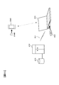
- FIG. 10 is a block diagram illustrating a configuration of an imaging system according to Modification 5. It is a figure explaining supply of the program to a mobile device.
- FIG. 1 is a block diagram illustrating the configuration of an electronic device (for example, camera 1) according to an embodiment.
- the camera 1 includes an imaging optical system 31, an imaging unit 32, an image processing unit 33, a work memory 34, a control unit 35, a liquid crystal monitor 36, an operation member 37, and a nonvolatile memory 38. And a recording unit 39 and a light emitting device 40.
- the imaging optical system 31 guides the light flux from the object scene to the imaging unit 32.
- the imaging unit 32 includes an imaging device 100 and a driving unit 32a, and photoelectrically converts an image of a subject formed by the imaging optical system 31.
- the imaging unit 32 can capture an image on the entire imaging surface of the imaging element 100 under the same conditions, or can capture an image on different conditions for each area of the imaging surface of the imaging element 100. Details of the imaging unit 32 will be described later.
- the drive unit 32a generates a drive signal necessary for causing the image sensor 100 to perform accumulation control.
- An imaging instruction such as a charge accumulation time for the imaging unit 32 is transmitted from the control unit 35 to the driving unit 32a.
- the image processing unit 33 performs image processing on the image data captured by the imaging unit 32 in cooperation with the work memory 34.
- the image processing includes, for example, contour enhancement processing, gamma correction, white balance adjustment, display luminance adjustment, saturation adjustment, and the like.
- the image processing unit 33 may perform image processing by applying the same parameter or the like to the entire area of the image, or may perform image processing by applying a different parameter or the like for each region of the image. it can.
- the work memory 34 is a memory in which image data before and after image processing is temporarily recorded.
- the control unit 35 is configured by a CPU, for example, and controls the overall operation of the camera 1. For example, a predetermined exposure calculation is performed based on the image signal acquired by the imaging unit 32, and the charge accumulation time (exposure time) of the image sensor 100 necessary for proper exposure, the aperture value of the imaging optical system 31, ISO sensitivity, and the like. The exposure condition is determined and an instruction is given to the drive unit 32a.
- image processing conditions for adjusting saturation, contrast, sharpness, and the like are determined and instructed to the image processing unit 33 according to the imaging scene mode set in the camera 1 and the type of the detected subject element. The detection of the subject element will be described later. Furthermore, when the setting for permitting the light emission of the light emitting device 40 is performed, the light emission amount of the light emitting device 40 necessary for proper exposure is determined and the light emitting device 40 is instructed.
- the control unit 35 includes an object detection unit 35a, an area segmentation unit 35b, a setting unit 35c, an imaging condition setting unit 35d, an imaging control unit 35e, an AF calculation unit 35f, and a display control unit 35g. . These are realized by software by the control unit 35 executing a program stored in the nonvolatile memory 38, but these may be configured by an ASIC or the like.
- the object detection unit 35a performs a known object recognition process, and from the image acquired by the imaging unit 32, an animal (animal face) such as a person (person's face), a dog, or a cat, a plant, a bicycle, an automobile , Detecting a subject element such as a vehicle such as a train, a building, a stationary object, a landscape such as a mountain or a cloud, or a predetermined specific object.
- the area dividing unit 35b divides (divides) the imaging screen by the imaging unit 32 into a plurality of areas including the subject element detected as described above.
- the setting unit 35c ranks the plurality of regions divided by the region dividing unit 35b. The ordering method will be described later.
- the imaging condition setting unit 35d sets imaging conditions for a plurality of areas divided by the area dividing unit 35b.
- Imaging conditions include the exposure conditions (charge accumulation time, gain, ISO sensitivity, frame rate, etc.) and the image processing conditions (for example, white balance adjustment parameters, gamma correction curves, display brightness adjustment parameters, saturation adjustment parameters, etc.) ).
- the same imaging conditions can be set for all of the plurality of areas, or different imaging conditions can be set for the plurality of areas.
- the imaging control unit 35e controls the imaging unit 32 (imaging device 100) and the image processing unit 33 by applying the imaging conditions set for each region by the imaging condition setting unit 35d. Thereby, it is possible to cause the imaging unit 32 to perform imaging under different exposure conditions for each of the plurality of regions divided by the region dividing unit 35b.
- the region dividing unit It is possible to perform image processing under different image processing conditions for each of the plurality of regions divided by 35b.
- the AF calculation unit 35f performs automatic focus adjustment (autofocus: AF) calculation for focusing on a corresponding subject at a predetermined position (called a focus point) on the imaging screen.
- the AF calculation unit 35f sends a drive signal for moving the focus lens of the imaging optical system 31 to the in-focus position based on the AF calculation result.
- the AF method may be a contrast detection method or a phase difference detection method.
- the display control unit 35g controls display of an image to be displayed on the liquid crystal monitor 36.
- the display control unit 35g displays, for example, one image on the display surface of the liquid crystal monitor 36, or displays a plurality of images side by side on the display surface of the liquid crystal monitor 36. Further, the display control unit 35g scrolls and displays the image being displayed on the display surface of the liquid crystal monitor 36 in accordance with a user operation.
- the liquid crystal monitor 36 reproduces and displays the image processed by the image processing unit 33 and the image read out by the recording unit 39.
- the liquid crystal monitor 36 also displays an operation menu screen, a setting screen for setting imaging conditions, and the like.
- the operation member 37 is composed of various operation members such as a release button and a menu button.
- the operation member 37 sends an operation signal corresponding to each operation to the control unit 35.
- the operation member 37 includes a touch operation member provided on the display surface of the liquid crystal monitor 36.
- the non-volatile memory 38 records a program executed by the control unit 35.
- the recording unit 39 records image data or the like on a recording medium including a memory card (not shown).
- the recording unit 39 reads image data recorded on the recording medium in response to an instruction from the control unit 35.
- the light emitting device 40 is a photographing auxiliary light source that illuminates the subject. For example, when the light emission permission is set, the light emitting device 40 emits light with the light amount instructed from the control unit 35 in response to the light emission instruction from the control unit 35.
- FIG. 2 is a cross-sectional view of the multilayer image sensor 100.
- the imaging device 100 includes a backside illumination type imaging chip 113 that outputs a pixel signal corresponding to incident light, a signal processing chip 111 that processes the pixel signal, and a memory chip 112 that records the pixel signal.
- the imaging chip 113, the signal processing chip 111, and the memory chip 112 are stacked, and are electrically connected to each other by a conductive bump 109 such as Cu.
- incident light is incident mainly in the positive direction of the Z axis indicated by the white arrow.
- the surface on the side where incident light enters is referred to as a back surface (imaging surface).
- the left direction of the paper orthogonal to the Z axis is the X axis plus direction
- the front side of the paper orthogonal to the Z axis and the X axis is the Y axis plus direction.
- the coordinate axes are displayed so that the orientation of each figure can be understood with reference to the coordinate axes in FIG.
- the imaging chip 113 is a back-illuminated MOS image sensor.
- the PD layer 106 is disposed on the back side of the wiring layer 108.
- the PD layer 106 includes a plurality of PDs (photodiodes) 104 that are two-dimensionally arranged and store charges corresponding to incident light, and transistors 105 that are provided corresponding to the PDs 104.
- a color filter 102 is provided on the incident light incident side of the PD layer 106 via a passivation film 103.
- the color filter 102 has a plurality of types that transmit different wavelength regions, and has a specific arrangement corresponding to each of the PDs 104. The arrangement of the color filter 102 will be described later.
- a set of the color filter 102, the PD 104, and the transistor 105 forms one pixel.
- a microlens 101 is provided on the incident light incident side of the color filter 102 corresponding to each pixel.
- the microlens 101 condenses incident light toward the corresponding PD 104.
- the wiring layer 108 includes a wiring 107 that transmits a pixel signal from the PD layer 106 to the signal processing chip 111.
- the wiring 107 may be multilayer, and a passive element and an active element may be provided.
- a plurality of bumps 109 are arranged on the surface of the wiring layer 108.
- the plurality of bumps 109 are aligned with the plurality of bumps 109 provided on the opposing surfaces of the signal processing chip 111, and the imaging chip 113 and the signal processing chip 111 are pressed and aligned.
- the bumps 109 are joined and electrically connected.
- a plurality of bumps 109 are arranged on the mutually facing surfaces of the signal processing chip 111 and the memory chip 112.
- the bumps 109 are aligned with each other, and the signal processing chip 111 and the memory chip 112 are pressurized, so that the aligned bumps 109 are joined and electrically connected.
- the bonding between the bumps 109 is not limited to Cu bump bonding by solid phase diffusion, and micro bump bonding by solder melting may be employed. Further, for example, about one bump 109 may be provided for one block described later. Therefore, the size of the bump 109 may be larger than the pitch of the PD 104. Further, a bump larger than the bump 109 corresponding to the pixel region may be provided in a peripheral region other than the pixel region where the pixels are arranged.
- the signal processing chip 111 has TSVs (silicon through electrodes) 110 that connect circuits provided on the front and back surfaces to each other.
- the TSV 110 is preferably provided in the peripheral area.
- the TSV 110 may also be provided in the peripheral area of the imaging chip 113 and the memory chip 112.
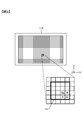
- FIG. 3 is a diagram for explaining the pixel array and the unit area 131 of the imaging chip 113.
- a state where the imaging chip 113 is observed from the back surface (imaging surface) side is shown.
- 20 million or more pixels are arranged in a matrix in the pixel region.
- adjacent 16 pixels of 4 pixels ⁇ 4 pixels form one unit region 131.
- the grid lines in the figure indicate the concept that adjacent pixels are grouped to form a unit region 131.
- the number of pixels forming the unit region 131 is not limited to this, and may be about 1000, for example, 32 pixels ⁇ 64 pixels, or more or less.
- the unit region 131 in FIG. 3 includes four so-called Bayer arrays, which are composed of four pixels of green pixels Gb, Gr, blue pixels B, and red pixels R, vertically and horizontally.
- the green pixels Gb and Gr are pixels having a green filter as the color filter 102, and receive light in the green wavelength band of incident light.
- the blue pixel B is a pixel having a blue filter as the color filter 102 and receives light in the blue wavelength band
- the red pixel R is a pixel having a red filter as the color filter 102 and having a red wavelength band. Receives light.
- a plurality of blocks are defined so as to include at least one unit region 131 per block, and each block can control pixels included in each block with different control parameters. That is, it is possible to acquire imaging signals having different imaging conditions between a pixel group included in a certain block and a pixel group included in another block.
- the control parameters include a frame rate, a gain, a thinning rate, the number of addition rows or addition columns to which pixel signals are added, a charge accumulation time or accumulation count, a digitization bit number (word length), and the like.
- the imaging element 100 can freely perform not only thinning in the row direction (X-axis direction of the imaging chip 113) but also thinning in the column direction (Y-axis direction of the imaging chip 113).
- the control parameter may be a parameter in image processing after obtaining an image signal from a pixel.
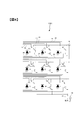
- FIG. 4 is a diagram for explaining a circuit in the unit region 131.
- one unit region 131 is formed by 9 pixels of 3 pixels ⁇ 3 pixels adjacent to each other.
- the number of pixels included in the unit region 131 is not limited to this, and may be less than this or more.
- the two-dimensional position of the unit area 131 is indicated by symbols A to I.
- the reset transistors of the pixels included in the unit region 131 are configured to be turned on and off individually for each pixel.
- a reset wiring 300 for turning on / off the reset transistor of the pixel A is provided, and a reset wiring 310 for turning on / off the reset transistor of the pixel B is provided separately from the reset wiring 300.
- a reset line 320 for turning on and off the reset transistor of the pixel C is provided separately from the reset lines 300 and 310.
- dedicated reset wirings for turning on and off the respective reset transistors are provided.
- the transfer transistors of the pixels included in the unit region 131 are also configured to be turned on and off individually for each pixel.
- a transfer wiring 302 for turning on / off the transfer transistor of the pixel A, a transfer wiring 312 for turning on / off the transfer transistor of the pixel B, and a transfer wiring 322 for turning on / off the transfer transistor of the pixel C are separately provided.
- dedicated transfer wirings for turning on / off the respective transfer transistors are provided for the other pixels D to I.
- the selection transistors of the pixels included in the unit region 131 are also configured to be turned on and off individually for each pixel.
- a selection wiring 306 for turning on / off the selection transistor of the pixel A, a selection wiring 316 for turning on / off the selection transistor of the pixel B, and a selection wiring 326 for turning on / off the selection transistor of the pixel C are separately provided.
- a dedicated selection wiring for turning on and off each selection transistor is provided for the other pixels D to I.
- the power supply wiring 304 is commonly connected from the pixel A to the pixel I included in the unit region 131.
- the output wiring 308 is commonly connected from the pixel A to the pixel I included in the unit region 131.
- the power supply wiring 304 is commonly connected between a plurality of unit regions, but the output wiring 308 is provided for each unit region 131 individually.
- the load current source 309 supplies current to the output wiring 308.
- the load current source 309 may be provided on the imaging chip 113 side or may be provided on the signal processing chip 111 side.
- the charge accumulation including the charge accumulation start time, the accumulation end time, and the transfer timing is controlled from the pixel A to the pixel I included in the unit region 131. can do.
- the pixel signals of the pixels I from each pixel A can be output via the common output wiring 308.
- a so-called rolling shutter system in which charge accumulation is controlled in a regular order with respect to rows and columns for pixels A to I included in the unit region 131.
- pixel signals are output in the order of “ABCDEFGHI” in the example of FIG.
- the charge accumulation time can be controlled for each unit region 131.
- the unit area 131 included in another block is rested while the unit areas 131 included in some blocks perform charge accumulation (imaging). Only the image can be taken and the pixel signal can be output.
- FIG. 5 is a block diagram illustrating a functional configuration of the image sensor 100 corresponding to the circuit illustrated in FIG.
- the analog multiplexer 411 sequentially selects the nine PDs 104 forming the unit region 131 and outputs each pixel signal to the output wiring 308 provided corresponding to the unit region 131.
- the multiplexer 411 is formed on the imaging chip 113 together with the PD 104.
- the pixel signal output via the multiplexer 411 is supplied to the signal processing chip 111 by a signal processing circuit 412 that performs correlated double sampling (CDS) / analog / digital (A / D) conversion. D conversion is performed.
- CDS correlated double sampling
- a / D converted pixel signal is transferred to the demultiplexer 413 and stored in the pixel memory 414 corresponding to each pixel.
- the demultiplexer 413 and the pixel memory 414 are formed in the memory chip 112.
- the arithmetic circuit 415 processes the pixel signal stored in the pixel memory 414 and passes it to the subsequent image processing unit.
- the arithmetic circuit 415 may be provided in the signal processing chip 111 or may be provided in the memory chip 112. Note that FIG. 5 shows connections for one unit region 131, but actually these exist for each unit region 131 and operate in parallel. However, the arithmetic circuit 415 does not have to exist for each unit region 131. For example, one arithmetic circuit 415 may perform sequential processing while sequentially referring to the values of the pixel memory 414 corresponding to each unit region 131. Good.
- the output wiring 308 is provided corresponding to each of the unit areas 131. Since the image pickup device 100 includes the image pickup chip 113, the signal processing chip 111, and the memory chip 112, each chip is arranged in the plane direction by using an electrical connection between the chips using the bump 109 for the output wiring 308. Wiring can be routed without increasing the size.
- an imaging condition can be set for each of a plurality of blocks in the imaging device 100 (imaging chip 113).
- the control unit 35 causes the region divided by the region dividing unit 35b to correspond to the block, and performs imaging under the imaging condition set for each region.
- the user sets imaging conditions for a desired area while confirming a live view image displayed on the display surface of the liquid crystal monitor 36, for example.
- the live view image refers to a monitor image that is repeatedly imaged at a predetermined frame rate (for example, 60 fps).
- the control unit 35 causes the image processing unit 33 to perform image processing on that area of the live view image.
- the image processing performed here is image processing for confirming the effect of changing the imaging condition. For example, when a change to increase the luminance is made, image processing to increase the display luminance displayed on the liquid crystal monitor 36 is performed. For example, when the light emitting device 40 is changed to emit light, image processing for increasing the display luminance displayed on the liquid crystal monitor 36 is performed for a predetermined subject element (for example, a person). Furthermore, for example, when a change for increasing the saturation is made, image processing for increasing the saturation is performed on a predetermined subject element (for example, a flower) displayed on the liquid crystal monitor 36.
- a predetermined subject element for example, a flower
- the user can confirm the effect of changing the imaging condition on the live view image that has been subjected to image processing before the actual imaging.
- the imaging condition setting for each region will be described in detail below.
- the method of performing image processing and displaying on the liquid crystal monitor 36 to confirm the effect of the change of the imaging condition operated for a certain area but also the change of the imaging condition operated for a certain area
- a method of displaying on the liquid crystal monitor 36 a live view image of the imaging condition set (changed) reflected on the imaging element corresponding to the region may be used.
- FIG. 6 is a diagram schematically showing a subject image formed on the image sensor 100 of the camera 1.
- the camera 1 photoelectrically converts the subject image to obtain a live view image before an imaging instruction is given.
- the control unit 35 first sets the same imaging condition over the entire area of the imaging chip 113 (that is, the entire area of the imaging surface).
- the exposure condition is determined based on the exposure condition calculated to obtain an appropriate exposure according to the photometric value of the subject luminance or the exposure condition manually set by the user.
- the image processing condition is determined as an image processing condition prepared in advance so as to obtain a standard image quality.
- the imaging condition determined in this way is referred to as a reference condition.
- An image acquired by applying the reference condition is called a reference image.
- the control unit 35 In response to an operation signal from an exposure mode changeover switch constituting the operation member 37, the control unit 35 performs a “program auto” mode, a “shutter speed priority auto” mode, an “aperture priority auto” mode, and a “manual” mode. Select one of them.
- the control unit 35 calculates the exposure conditions (charge accumulation time, gain, ISO sensitivity, frame rate, etc.) by performing a predetermined exposure calculation according to the selected exposure mode.
- the control unit 35 determines an aperture value, a shutter speed (charge accumulation time), a gain, and the like so that the average luminance in the screen is appropriate.
- the control unit 35 uses the shutter speed (charge accumulation time) set by the user, for example, to set an aperture value, a gain, and the like so that the average brightness in the screen is appropriate. decide.
- the control unit 35 determines a shutter speed (charge accumulation time), a gain, and the like so that the average brightness in the screen is appropriate, for example, using the aperture value set by the user. To do.
- the control unit 35 calculates the deviation from the appropriate exposure based on the aperture value set by the user and the shutter speed (charge accumulation time).
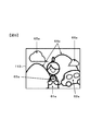
- an image including a person 61a, an automobile 62a, a bag 63a, a mountain 64a, and clouds 65a and 66a is formed on the imaging surface of the imaging chip 113.
- the person 61a holds the bag 63a with both hands.
- the automobile 62a stops at the right rear of the person 61a.
- the control unit 35 divides the image acquired as the live view image into a plurality of regions as follows.
- the subject element is detected from the live view image by the object detection unit 35a.
- the subject element is detected using a known subject recognition technique.
- the object detection unit 35a detects a person 61a, a car 62a, a bag 63a, a mountain 64a, a cloud 65a, and a cloud 66a as subject elements.
- an image acquired as a live view image is divided into regions including subject elements by the region dividing unit 35b based on the detection means.
- the area including the person 61a is the first area 61
- the area including the car 62a is the second area 62
- the area including the bag 63a is the third area 63
- the area including the mountain 64a is the fourth area 64.
- the region including the cloud 65a is referred to as a fifth region 65
- the region including the cloud 66a is referred to as a sixth region 66.
- the setting unit 35c ranks the plurality of regions divided by the region dividing unit 35b.
- the setting unit 35c detects the following regions (1) to (4) among the regions divided by the region dividing unit 35b, the setting unit 35c prioritizes the imaging condition over the other regions divided by the region dividing unit 35b.
- (1) Region in which a specific subject is detected according to the imaging scene mode The specific subject differs depending on the imaging scene mode of the camera 1 that has been set. For example, when the imaging scene mode setting of the camera 1 is set to the portrait mode, the setting unit 35c sets the area including the automobile 62a as the second area 62 with respect to the first area 61 including the person 61a.
- the region including the bag 63 a is the third region 63, the region including the mountain 64 a is the fourth region 64, the region including the cloud 65 a is the fifth region 65, and the region including the cloud 66 a is the imaging condition than the sixth region 66.
- the setting unit 35c When the imaging scene mode setting of the camera 1 is set to the close-up mode and a flower is detected as a subject element by the object detection unit 35a, the setting unit 35c The imaging condition is set as a region that is changed with priority over other regions. In the case of the close-up mode, it is based on the idea that there is a high possibility of setting (changing) the imaging condition of the region including the flower.
- the setting unit 35c It is set as an area where imaging conditions are changed with priority over other areas.
- the landscape mode it is based on the idea that there is a high possibility of setting (changing) the imaging condition of the area including the mountain.
- the setting unit 35c It is set as an area where imaging conditions are changed with priority over other areas.
- the beach mode it is based on the idea that there is a high possibility of setting (changing) the imaging condition of the region including the sea.
- the setting unit 35c applies to the region including the red sky.
- the region including the red sky is set as an area where the imaging condition is changed with priority over other areas.
- the sunset mode it is based on the idea that there is a high possibility of setting (changing) the imaging condition of the region including the red sky.
- the setting unit 35c Is set as a region in which the imaging condition is changed with priority over other regions.
- the cooking mode it is based on the idea that there is a high possibility of setting (changing) the imaging conditions of an area including dishes on a plate.
- the setting of the imaging scene mode of the camera 1 may be set by the user operating the operation member 37 or may be set by the control unit 37 based on the subject element detected from the screen of the live view image. It may be.
- the setting unit 35c displays the subject element in focus (that is, the focus point). Is determined as a region in which the imaging condition is preferentially changed over a region including a subject element that is not in focus.
- an image is captured of an area including the subject element with the smallest focus shift amount (that is, the closest subject element from the subject element position to the in-focus position). You may make it determine as an area
- the setting unit 35c selects the subject element with the darkest or brightest subject element from among the plurality of subject elements detected by the object detection unit 35a.
- the area to be included is determined as an area in which the imaging condition is changed with priority over other areas.
- An area including a subject element that is too dark, such as blackout, or a subject element that is too bright, such as overexposure, is based on the idea that there is a high possibility of setting (changing) the imaging condition.
- the setting unit 35c includes the above-described green pixels Gb, Gr, or blue pixels B, among the plurality of subject elements detected by the object detection unit 35a.
- an area including a subject element in which the ratio of the color components of the red pixel R is higher than the ratio of the other color components is determined as an area where the imaging condition is changed with priority over the other areas.
- an area including subject elements such as sky blue, sea blue, mountain green, and sunset red is based on the idea that there is a high possibility of setting (changing) imaging conditions.
- the setting unit 35c is a region in which the imaging condition is preferentially changed over the subject element closest to the camera 1 over the subject element far away. decide.
- the control unit 35 acquires distance information from the camera 1 to the segmented subject element, and determines a region including the subject element closest to the camera 1.
- the control unit 35 may determine an area including the subject element having the largest proportion of the screen as the subject element close to the camera 1.
- the setting unit 35c When the setting unit 35c detects the following regions (6) to (10) among the regions divided by the region dividing unit 35b, the setting unit 35c sets the rank lower than the regions (1) to (5) described above. Thus, the imaging condition is determined as a region to be changed.
- the setting unit 35c includes a plurality of detection points detected by the object detection unit 35a.
- the area including the subject element with the smallest focus deviation amount among the areas other than the area including the focused subject element is set as the area where the imaging condition is changed with priority over the other areas. Set.
- the smaller the amount of focus shift the higher the sharpness of the contour of the subject element. Therefore, it can be said that the subject element having a high contour sharpness has a small amount of focus shift.
- the setting unit 35c sets an area including a subject element having a high outline sharpness as an area in which the imaging condition is preferentially changed over an area having a low outline sharpness.
- Example 1 For example, in FIG. 6, a case is assumed where the person 61a is in focus due to the AF operation performed on the first region 61 by the AF calculation unit.
- the setting unit 35c sets the subject element having the smallest focus shift amount among the automobile 62a, the bag 63a, the mountain 64a, the cloud 65a, and the cloud 66a (that is, from the position of the person 61a in focus).
- the third region 63 including the bag 63a) at a close position is set as a region for preferentially changing the imaging condition after the first region 61 including the person 61a. Based on the idea that the imaging condition of the third region 63 including the bag 63a is likely to be set (changed) next to the first region 61 including the person 61a.
- Example 2 For example, in FIG. 6, a case is assumed in which the AF calculation unit focuses between the person 61a and the car 62a.
- the setting unit 35c has a subject element with the smallest focus shift amount among the automobile 62a, the bag 63a, the mountain 64a, the cloud 65a, and the cloud 66a (that is, the closest position from the focused position).
- the second area 62 including a certain automobile 62a) is set as an area in which the imaging condition is preferentially changed after the first area 61 including the person 61a. Based on the idea that the imaging condition of the second area 62 including the automobile 62a is likely to be set (changed) next to the first area 61 including the person 61a.
- the setting unit 35c sets an order based on the difference in distance from the camera 1 to the subject element. For example, in FIG. 6, it is assumed that the person 61a is in focus by performing the AF operation on the first region 61. In this case, the setting unit 35c determines that the distance from the camera 1 among the automobile 62a, the bag 63a, the mountain 64a, the cloud 65a, and the cloud 66a is close to the distance from the camera 1 to the person 61a (distance difference).
- the region including the subject element is set as a region for preferentially changing the imaging condition.
- Region including Subject Element with Large Brightness Difference For example, in FIG. 6, a case is assumed where the person 61a is in focus due to the AF operation performed on the first region 61.
- the setting unit 35c sets a region including the subject element having the largest luminance difference between the person 61a among the automobile 62a, the bag 63a, the mountain 64a, the cloud 65a, the cloud 65a, and the cloud 66a.
- the imaging condition is set as an area to be preferentially changed.
- the setting unit 35c preferentially sets the imaging condition to the fourth area 64 including the mountain 64a next to the first area 61 including the person 61a.
- An area including a subject element having a large luminance difference with the person 61a is based on the idea that there is a high possibility that an imaging condition is set (changed).
- (9) Region including a large subject element When the magnitude relationship of the difference in focus shift amount between the regions including the subject element is poor and the luminance difference between the regions is also poor, the setting unit 35c A region including a subject element larger than the element, in other words, a region having a larger occupied area in the screen is set as a region for preferentially changing the imaging condition.
- the setting unit 35c The region including the subject element closer to the center of the screen is set as a region for preferentially changing the imaging condition.
- any one of the above (6) to (10) may be selected in advance by operating the operation member 37 by the user.
- a plurality of (6) to (10) may be combined.
- the setting unit 35c ranks the second area 63 to the sixth area 66.
- the second area 62 including the automobile 62a which is a large subject element is ranked second
- the third area 63 including the bag 63a is ranked third
- the fourth area 64 including the mountain 64a is ranked fourth and includes the cloud 65a.
- the fifth region 65 is fifth
- the sixth region 66 including the cloud 66a is sixth.
- the setting unit 35c treats an area that has not been ordered even after the processing of (6) to (10) above as having an equivalent order.
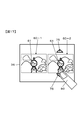
- the control unit 35 causes the liquid crystal monitor 36 to display a setting screen as illustrated in FIG.
- a live view image 60a is displayed, and an icon 71 and an icon 72 are displayed over the live view image 60a.
- the live view image 60a is a reference image acquired by applying the above-described reference conditions.
- the icon 71 is an operation icon for selecting “luminance” as an example of the setting item of the imaging condition.
- the icon 72 is an operation icon for selecting “saturation” as an example of an imaging condition setting item. Operation icons for selecting setting items for imaging conditions may be added as appropriate in addition to those illustrated in FIG.
- the imaging condition setting item may be selected and determined by the photographer, but may be determined and determined by the control unit 35 of the camera 1 from the detected subject image.
- the areas to be displayed with emphasis are set (changed) of the imaging conditions.
- the first area 61 is a target for setting (changing) the imaging condition.
- the first target for setting (changing) the imaging condition is the region in which the ranking given by the setting unit 35 c is first.
- the control unit 35 sets (changes) the highlighted area (first area 61) as a target.
- Select brightness as a setting item for imaging conditions.
- an imaging condition setting item may be selected by operating a button or the like constituting the operation member 37.
- the control unit 35 that has selected luminance as the setting item of the imaging condition sets the luminance of the first region 61 that is the target of setting (change) of the imaging condition in the live view image.
- the imaging condition corresponding to the first region 61 is determined so as to be higher (or lower) than the luminance of the reference image.
- the set imaging conditions are maintained so as to maintain the brightness of the reference image.
- the regions that are not subject to setting (changing) of the imaging conditions in the vicinity of the boundary with the first region 61, considering the balance of the entire image so as to blur the discontinuity of the imaging conditions in the vicinity of the boundary.
- the imaging conditions may be changed.
- the imaging condition setting unit 35d makes the charge accumulation time longer than the charge accumulation time of the reference condition among the imaging conditions of the first region 61, or increases the gain.
- the imaging condition for increasing the luminance is determined by increasing the gain compared to the reference condition gain.
- the imaging condition setting unit 35d may, for example, shorten the charge accumulation time among the imaging conditions of the first region 61 compared to the charge accumulation time of the reference condition, Is set lower than the gain of the reference condition to determine the imaging condition for reducing the luminance.
- the imaging condition setting unit 35d determines the imaging conditions for increasing or decreasing the luminance so that the luminance is gradually different from the luminance obtained in the reference condition (for example, eight levels). To decide.
- the upper limit in the case of increasing the brightness is set to a value that does not saturate (so-called whiteout) the high brightness area in the first area 61 of the live view image.
- the lower limit in the case of lowering the luminance is a value in which the low luminance region in the first region 61 of the live view image is not too dark (so-called black crushing).
- the imaging condition setting unit 35d determines the multi-stage imaging conditions for raising and lowering the luminance for the first region 61 as described above, and sets the multi-stage imaging conditions determined for the luminance in the image processing unit 33.
- the reason for setting the image processing unit 33 is to obtain a multi-stage candidate image to be described later by performing image processing on the live view image.
- the control unit 35 that has selected the saturation as the setting item of the imaging condition sets the saturation of the first region 61 that is the target of setting (changing) of the imaging condition in the live view image.
- the imaging condition corresponding to the first region 61 is determined so that is higher (or lower) than the saturation of the reference image.
- the set imaging condition is maintained so as to maintain the saturation of the reference image.
- the regions that are not subject to setting (changing) of the imaging conditions in the vicinity of the boundary with the first region 61, considering the balance of the entire image so as to blur the discontinuity of the imaging conditions in the vicinity of the boundary.
- the imaging conditions may be changed.
- the imaging condition setting unit 35d When increasing the saturation of the first area 61, the imaging condition setting unit 35d reads out signals read from, for example, the green pixel Gb, Gr, the blue pixel B, or the red pixel R among the imaging conditions of the first area 61.
- the image capturing condition for making a specific color vivid is determined by relatively increasing the value of the color signal compared to the signal values of the other color components.
- the imaging condition setting unit 35d is read from, for example, the green pixels Gb, Gr, the blue pixel B, and the red pixel R among the imaging conditions of the first region 61.
- the imaging condition for suppressing the vividness of a specific color is determined by relatively lowering the value of the signal of the color component protruding from the other color components in the signal.
- the imaging condition setting unit 35d determines an imaging condition for increasing or decreasing the saturation
- the imaging condition setting unit 35d performs imaging in multiple stages (e.g., eight stages) so that the saturation is gradually different from the saturation obtained in the reference condition. Determine the conditions.
- the upper limit for increasing the saturation is a value that does not saturate the signal of high saturation (protruding color component) in the first region 61 of the live view image.
- the lower limit for lowering the saturation is a value that does not suppress the vividness until the color in the first region 61 of the live view image becomes an achromatic color.
- the imaging condition setting unit 35d determines the multi-stage imaging conditions for raising and lowering the saturation for the first region 61 as described above, and sets the multi-stage imaging conditions determined for the saturation in the image processing unit 33. To do.
- the reason for setting the image processing unit 33 is to obtain a multi-stage candidate image to be described later by performing image processing on the live view image.
- the imaging condition setting unit 35d sets the first region 61 including the person 61a so as to lower the saturation of the person. An imaging condition corresponding to one area 61 is determined.
- the imaging condition setting unit 35d increases the saturation of the mountain in the region including the mountain 64a as the background with respect to the fourth region 64 (for example, the values of the signals read from the green pixels Gr and Gb are changed to other values).
- the imaging condition corresponding to the fourth region 64 is determined so as to be relatively higher than the value of the color component signal.
- the portrait mode it is based on the idea that the background is vivid and there is a high possibility that the person 61a will be brought out.
- the imaging condition setting unit 35d In addition, the imaging condition is determined so as to increase the saturation for the area including the dish.
- the imaging condition setting unit 35d includes an area including red autumnal leaves.
- the imaging condition is determined so as to increase the saturation (for example, the value of the signal read from the red pixel R is relatively higher than the values of the signals of the other color components). The same applies when the imaging scene mode setting of the camera 1 is the sunset mode.
- the imaging condition setting unit 35d is an area including the sea and the sky.
- the imaging conditions are determined so as to increase the saturation (for example, the value of the signal read from the blue pixel B is relatively higher than the values of the signals of the other color components).
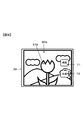
- FIG. 8 is a diagram illustrating a setting screen of the liquid crystal monitor 36 that displays a live view image 60b different from the live view image 60a.
- the setting unit 35c applies to the region including the red flower. Rank first.
- the outline of the first area 61b is highlighted and displayed as a target area for setting (changing) the imaging conditions.
- the close-up mode it is based on the idea that there is a high possibility of setting (changing) the imaging condition of an area including a flower preferentially over other areas.
- the icons 71 and 72 in FIG. 8 are the same as those in the setting screen illustrated in FIG.
- the control unit 35 that has selected the saturation as the setting item for the imaging condition applies to the first region 61 b that is the target for setting (changing) the imaging condition in the live view image.
- the imaging conditions are determined so as to increase the saturation (for example, the value of the signal read from the red pixel R is relatively higher than the values of the signals of the other color components).
- the imaging condition for making the color of the red flower bright is determined by relatively increasing the value of the signal read from the red pixel R as compared with the values of the signals of the other color components.
- the imaging condition setting unit 35d receives the signals read from the green pixels Gb, Gr, the blue pixels B, and the red pixels R for each color of the subject element in the region divided by the region dividing unit 35b. Of these, by changing the value of the signal of the color component that protrudes compared to the other color components, the imaging condition with the saturation changed is determined.
- the image processing unit 33 includes the first region 61 in the reference area obtained by applying the reference condition.
- a plurality of images (eight images in the case of the above eight steps) having different luminance levels are generated.
- the plurality of images generated in this way are referred to as candidate images.
- the plurality of candidate images generated by the image processing unit 33 are temporarily recorded in the work memory 34.
- the image processing unit 33 sets the saturation of the image in the first region 61b in the reference image when the imaging condition setting unit 35d sets the above-described multi-level imaging conditions for the saturation.
- a plurality of different images in multiple stages are generated. These multiple images are also called candidate images.
- the plurality of candidate images generated by the image processing unit 33 are temporarily recorded in the work memory 34.
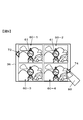
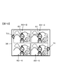
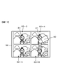
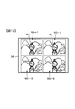
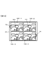
- the display control unit 35g displays the candidate images side by side on the display surface of the liquid crystal monitor 36 as shown in FIG. 9 to 12 are diagrams illustrating examples of the screen of the liquid crystal monitor 36 that displays the candidate images side by side.
- the display control unit 35g displays the candidate images for the luminances side by side on the display surface of the liquid crystal monitor 36 when the candidate images having the above-described different luminances in multiple stages are recorded in the work memory 34. Further, when the candidate images having different saturations described above are recorded in the work memory 34, the display control unit 35g arranges the candidate images for the saturations on the display surface of the liquid crystal monitor 36. Display.
- candidate images 60-1 to 60-4 among the eight candidate images are displayed.
- Candidate image 60-2 is one step higher in luminance (or saturation) than candidate image 60-1.
- Candidate image 60-3 is one step higher in luminance (or saturation) than candidate image 60-2.
- Candidate image 60-4 is one step higher in luminance (or saturation) than candidate image 60-3.
- a left icon 73 is displayed at the left position of the candidate image 60-1, and a right icon 74 is displayed at the right position of the candidate image 60-4.
- the display control unit 35g displays four candidate images (candidate images) among the eight candidate images as illustrated in FIG. 60-2 to candidate images 60-5) are displayed.
- the candidate image 60-1 displayed in FIG. 9 is not displayed, and the candidate image 60-5 not displayed in FIG. 9 is newly displayed.
- Candidate image 60-5 is one step higher in luminance (or saturation) than candidate image 60-4.
- the display control unit 35 g displays four of the eight candidate images as illustrated in FIG. 9. Two candidate images (candidate images 60-1 to 60-4) are displayed. That is, the candidate image 60-5 displayed in FIG. 10 is not displayed, and the candidate image 60-1 not displayed in FIG. 10 is newly displayed.
- FIG. 11 is a diagram illustrating a screen of the liquid crystal monitor 36 that displays four candidate images (candidate images 60-3 to 60-6) among the eight candidate images.
- the candidate image 60-6 is one level higher in brightness than the candidate image 60-5.
- the display control unit 35g displays eight candidate images as illustrated in FIG. Of these, four candidate images (candidate images 60-1 to 60-4) are displayed. According to FIG. 12, the candidate image 60-4 and candidate image 60-5 displayed in FIG. 11 are not displayed, and the candidate image 60-1 and candidate image 60-2 not displayed in FIG. Is displayed.
- the user can confirm a plurality of candidate images. Further, the user can display and confirm other candidate images that are not displayed on the liquid crystal monitor 36 by performing a tap operation on the left icon 73 or the right icon 74 or a slide operation with the finger 80.
- FIG. 13 is a diagram exemplifying a screen of the liquid crystal monitor 36 that displays candidate images having different saturations in multiple stages.
- four candidate images candidate images 160-1 to 160-4) of eight candidate images are displayed.
- Candidate image 160-2 is one step higher in saturation than candidate image 160-1.
- Candidate image 160-3 is one step higher in saturation than candidate image 160-2.
- Candidate image 160-4 is one step higher in saturation than candidate image 160-3.
- ⁇ Selection operation> The user selects an arbitrary candidate image from among the plurality of candidate images. For example, when the user double-taps the position where an arbitrary candidate image is displayed among the plurality of candidate images on the screen illustrated in FIGS. 9 to 12 with the finger 80, the control unit 35 next issues an imaging instruction. When it is performed, the imaging condition to be applied to the first area 61 is determined as follows, and the screen returns to the state where the setting screen illustrated in FIG.
- control unit 35 sets the imaging condition applied to the first region 61 of the candidate image that has been double-tapped in the imaging unit 32 or the image processing unit 33.
- the reason for setting in the imaging unit 32 is to change the luminance by changing the exposure condition of the imaging device 100 at the next imaging.
- the reason for setting the image processing unit 33 is to change the saturation by changing the image processing condition of the image processing unit 33 at the next imaging.
- the imaging condition setting unit 35d sets the exposure condition for obtaining the luminance corresponding to the double-tapped candidate image to the first.
- the imaging condition (exposure condition) to be applied to the region 61 is determined, and the imaging control unit 35e sets the condition in the imaging unit 32.
- the imaging condition setting unit 35d obtains saturation corresponding to the double-tapped candidate image.
- the image processing condition for this is determined as the imaging condition (image processing condition) to be applied to the first region 161, and the imaging control unit 35e sets the condition in the image processing unit 33.
- the user can perform an operation of selecting an arbitrary candidate image from among the plurality of candidate images regarding saturation after performing an operation of selecting an arbitrary candidate image among the plurality of candidate images regarding luminance.
- the user can perform an operation of selecting an arbitrary candidate image from among the plurality of candidate images regarding luminance after performing an operation of selecting an arbitrary candidate image among the plurality of candidate images regarding the saturation.
- the user selects an arbitrary candidate image from among a plurality of candidate images regarding the luminance or the saturation even for the region other than the first region 61, that is, the region whose rank given by the setting unit 35c is second or lower. It can be performed. For example, when the user taps an area other than the first area 61 with a finger while the setting screen illustrated in FIG. 7 is displayed on the liquid crystal monitor 36, for example, the control unit 35 replaces the first area 61 with Highlight and display the tapped area.
- the imaging condition setting unit 35d sets the highlighted area as an object for setting (changing) the imaging condition. Subsequent setting operations are the same as those in the first area 61 described above.
- control unit 35 sets (changes) the imaging conditions in order of the areas where the order given by the setting unit 35c is second or lower. You may make it switch as an area
- the example of highlighting the outline of the area (first area 61 in the above example) targeted for setting (changing) the imaging condition has been described, but instead of outline enhancement, the contrast of the entire target area is set. It may be displayed in a raised manner, or the entire target area may be blinked. Further, the target area may be surrounded by a frame. The frame surrounding the target area may be displayed as a double frame or a single frame, and the display mode such as the line type of the surrounding frame may be appropriately changed.
- the control unit 35 may display an indication of an area for which the imaging condition is set with an arrow or the like in the vicinity of the target area. The control unit 35 may display the area other than the target area for which the imaging condition is set (changed) in a dark manner or display the area other than the target area with a lower contrast.
- the control unit 35 After the imaging conditions for the areas described above are set, when a release button (not shown) constituting the operation member 37 or a display for instructing to start imaging is operated, the control unit 35 causes each of the divided areas.
- the image is captured under the image capturing conditions set for the image data, image data that has undergone image processing is generated, and recorded on a recording medium including a memory card (not shown).
- FIG. 14 is a flowchart for explaining the flow of processing for setting an imaging condition for each area and imaging.
- the control unit 35 activates a program that executes the process shown in FIG.
- the control unit 35 causes the liquid crystal monitor 36 to start live view display, and proceeds to step S20.
- the control unit 35 instructs the imaging unit 32 to start acquiring a live view image, and sequentially displays the acquired live view image on the liquid crystal monitor 36. As described above, at this time, the same imaging condition is set over the entire area of the imaging chip 113, that is, the entire screen. If the setting for performing the AF operation is performed during live view display, the control unit 35 (AF calculation unit 35f) controls the AF operation for focusing on the subject element corresponding to the predetermined focus point. If the setting for performing the AF operation is not performed during the live view display, the control unit 35 (AF calculation unit 35f) performs the AF operation when the AF operation is instructed later.
- step S20 the control unit 35 (object detection unit 35a) detects the subject element from the live view image, and proceeds to step S30.
- step S30 the control unit 35 (region dividing unit 35b) divides the screen of the live view image into regions including subject elements, and proceeds to step S40.
- step S40 the control unit 35 determines the reference condition described above based on the setting state of the camera 1 or the state of the subject. That is, the same imaging condition is set over the entire screen, and the process proceeds to step S50.
- step S50 the control unit 35 acquires a live view image (reference image) to which the reference condition is applied, and proceeds to step S60.
- step S60 the control unit 35 selects a region to be set (changed) for imaging conditions from the regions divided by the region dividing unit 35b. For example, the control unit 35 selects the order given by the setting unit 35c in order from the first ranked region.
- step S70 the control unit 35 determines whether or not an operation for displaying a candidate image has been performed. As described above, when the user taps the icon 71 or 72 in FIG. 7 (or FIG. 8), the control unit 35 makes a positive determination in step S70 and proceeds to step S80. If not, a negative determination is made in step S70 and the process proceeds to step S120.
- step S80 the control unit 35 determines an imaging condition to be set (changed). That is, the control unit 35 determines the setting item corresponding to the icon 71 or 72 tapped by the user, and proceeds to step S90.
- step S90 the control unit 35 (imaging condition setting unit 35d) acquires a plurality of candidate images for the setting item determined in step S80, and proceeds to step S100.
- step S100 the control unit 35 displays a plurality of candidate images on the display surface of the liquid crystal monitor 36, and proceeds to step S110.
- step S110 when the user performs the selection operation (for example, double tap), the control unit 35 corresponds to the candidate image that has been double-tapped with respect to the region for which the imaging condition is to be set (changed).
- the imaging condition is determined, the condition is set in the imaging unit 32 or the image processing unit 33, and the process proceeds to step S120. Note that the display transition of the liquid crystal monitor 36 and the setting of the imaging condition according to the user operation in step S110 are as described above.
- step S120 the control unit 35 determines whether there is an imaging instruction.
- a release button (not shown) constituting the operation member 37 or a display for instructing imaging is operated, the control unit 35 makes a positive determination in step S120 and proceeds to step S130.
- the control unit 35 makes a negative determination in step S120 and returns to step S70.
- step S130 the control unit 35 performs a predetermined main imaging process. That is, the image capturing control unit 35e controls the image capturing unit 32 so as to perform image capturing under the image capturing conditions set for each region, and the image processing unit 33 performs predetermined image processing on the image data obtained by image capturing. Apply. Then, the recording unit 39 records the image data on a recording medium (not shown).
- step S140 the control unit 35 determines whether an end operation has been performed. When the end operation is performed, the control unit 35 makes a positive determination in step S140 and ends the process illustrated in FIG. When the end operation is not performed, the control unit 35 makes a negative determination in step S140 and returns to step S20. When returning to step S20, the control unit 35 repeats the above-described processing.
- the camera 1 has an imaging unit 32 that captures a subject image by the imaging element 100 configured to be able to set imaging conditions for a plurality of areas on the imaging surface, and parameters for changing the imaging conditions for each area. And a control unit 35 that determines based on the subject element detected from the captured live view image. As a result, the camera 1 automatically determines parameters for changing the imaging condition for each area, so that the user can easily set the imaging conditions for each area.
- the control unit 35 determines the parameter based on the subject element and the set imaging mode. As a result, appropriate parameters are automatically determined according to the type of subject element (eg, person, mountain, flower, etc.) and the imaging mode (eg, portrait mode, landscape mode, etc.). It becomes easy to set the imaging condition for each region.
- the type of subject element eg, person, mountain, flower, etc.
- the imaging mode eg, portrait mode, landscape mode, etc.
- the camera 1 generates a candidate image in which the imaging condition is changed using the parameter determined by the control unit 35 in at least one of the plurality of areas with respect to the captured live view image.
- a processing unit 33 is provided. Thereby, the user can confirm the effect when the imaging condition is changed for the region by using the candidate image obtained by performing the image processing on the live view image before performing the main imaging.
- the control unit 35 determines a plurality of parameters, and the image processing unit 33 uses a plurality of different parameters determined by the control unit 35 for the captured live view image in a stepwise manner. A plurality of changed candidate images are generated. Thereby, the user can compare the effect when the imaging condition is changed with a plurality of candidate images having different imaging conditions in stages.
- the imaging condition is luminance or saturation
- the image processing unit 33 generates a plurality of candidate images in which the luminance or saturation is changed stepwise. Accordingly, the user can compare the effect when the luminance (or saturation) is changed with a plurality of candidate images having different luminance (or saturation) in stages.
- the image processing unit 33 generates the captured live view image as a reference image before changing the imaging condition, and generates a candidate image after changing the imaging condition. Accordingly, the user can compare the effect when the imaging condition is changed with respect to the region before the imaging condition is changed.
- the image processing unit 33 generates a reference image, an image having a higher brightness than the reference image, and / or an image having a lower brightness than the reference image. Thereby, the user can compare the effect when the luminance is changed with respect to the region compared with before changing the luminance.
- the image processing unit 33 generates a reference image, an image with high saturation with respect to the reference image, and / or an image with low saturation with respect to the reference image. Thereby, the user can compare the effect when the saturation is changed with respect to the region compared with before changing the saturation.
- the display control unit 35g is configured to display, on the liquid crystal monitor 36, a region for displaying an image generated by changing the imaging condition by the image processing unit 33 among the plurality of regions. Thereby, it is possible to easily show the region that is the target of the setting (change) to the user.
- 15 and 16 are diagrams illustrating display screens according to the first modification.
- the display control unit 35g has a reference image (reference image) of the reference condition on the display surface of the liquid crystal monitor 36 as shown in FIG. 60-1) is displayed.
- the image in the first area 61 is the reference image 61-1.
- the outline of the first region 61 to be set (changed) for the imaging condition is highlighted, as in the case of the above embodiment.
- a left icon 73 is displayed at the left position of the first area 61
- a right icon 74 is displayed at the right position of the first area 61.
- the display control unit 35g selects only the image in the first area 61 as the candidate image 61-, as illustrated in FIG.
- the composite image replaced with 2 is displayed.
- the background other than the first area 61 remains the reference image 60-1.
- the candidate image 61-2 is an image that is one step higher in luminance (or saturation) than the candidate image 61-1.
- the display control unit 35g reads out the necessary candidate image 60-2 from the eight candidate images temporarily stored in the work memory 34 in response to the tap operation of the right icon 74, and the read candidate Of the image 60-2, only the candidate image 61-2 in the first region 61 is extracted and used for the composite display illustrated in FIG.
- the display control unit 35g displays the image in the first region 61 as illustrated in FIG. A composite image in which is replaced with the reference image 61-1 is displayed.
- the background other than the first area 61 remains the reference image 60-1.
- the user can confirm candidate images for the first region 61 that is the target of setting (changing) the imaging conditions. Further, the user can display and confirm other candidate images in the first area 61 by performing a tap operation on the left icon 73 or the right icon 74.
- the control unit 35 (imaging condition setting unit 35d) at that time
- the imaging condition applied to the candidate image 61-n (n is a natural number of 1 to 8) displayed in the first area 61 is applied to the first area 61 when the next imaging instruction is issued.
- the imaging condition is determined, and the screen returns to the state in which the setting screen illustrated in FIG.
- the user can perform an operation of selecting an arbitrary candidate image from among the plurality of candidate images regarding saturation after performing an operation of selecting an arbitrary candidate image among the plurality of candidate images regarding luminance, and As described above, the user can perform an operation of selecting an arbitrary candidate image from among the plurality of candidate images regarding luminance after performing an operation of selecting an arbitrary candidate image among the plurality of candidate images regarding the saturation. This is the same as the embodiment described above.
- the user can set (change) the imaging condition with respect to luminance or saturation even in the area other than the first area 61, that is, in the area where the order given by the setting unit 35c is second or lower. This is the same as the embodiment described above.
- (Modification 2) 17 and 18 are diagrams illustrating display screens according to the second modification.
- the display control unit 35g displays the reference image of the reference condition on the left side of the display surface of the liquid crystal monitor 36 (see FIG. 17).
- the outline of the first region 61 to be set (changed) for the imaging condition is highlighted, as in the case of the above embodiment.
- the upper icon 75 is displayed at the upper position of the right candidate image 60-2
- the lower icon 76 is displayed at the lower position of the candidate image 60-2.
- the display control unit 35g replaces the right candidate image 60-2 with the candidate image 60, as illustrated in FIG. -3 is displayed.
- the display of the left reference image 60-1 remains unchanged.
- Candidate image 60-3 is an image that is one step higher in luminance (or saturation) than candidate image 60-2.
- the display control unit 35g reads out the necessary candidate image 60-3 from the eight candidate images temporarily stored in the work memory 34 in response to the tap operation of the lower icon 76, and the result is shown in FIG. Used for the illustrated display.
- the display control unit 35g displays the right candidate image 60-3 as illustrated in FIG. Instead, the candidate image 60-2 is displayed.
- the display of the left reference image 60-1 remains unchanged.
- the user can confirm the candidate image together with the reference image.
- the user can display and confirm other candidate images that are not displayed on the liquid crystal monitor 36 by performing a tap operation on the upper icon 75 or the lower icon 76.
- the control unit 35 (imaging condition setting unit 35d) at that time
- the imaging condition applied to the candidate image 60-n (n is a natural number of 1 to 8) displayed on the right side of the display screen is applied to the first area 61 when an imaging instruction is next issued.
- the imaging condition is determined, and the screen returns to the state in which the setting screen illustrated in FIG.
- the user can perform an operation of selecting an arbitrary candidate image from among the plurality of candidate images regarding saturation after performing an operation of selecting an arbitrary candidate image among the plurality of candidate images regarding luminance, and As described above, the user can perform an operation of selecting an arbitrary candidate image from among the plurality of candidate images regarding luminance after performing an operation of selecting an arbitrary candidate image among the plurality of candidate images regarding the saturation. This is the same as the embodiment described above.
- the user can set (change) the imaging condition with respect to luminance or saturation even in the area other than the first area 61, that is, in the area where the order given by the setting unit 35c is second or lower. This is the same as the embodiment described above.
- the reference condition As an example of determining the reference condition, one of “program auto” mode, “shutter speed priority auto” mode, “aperture priority auto” mode, and “manual” mode is selected and selected.
- the appropriate exposure is determined by performing a predetermined exposure calculation according to the exposure mode, and the image processing conditions prepared in advance so as to obtain a standard image quality are determined, and the determined exposure conditions and image processing conditions are determined.
- An example in which the reference condition is used has been described. Instead of this, the reference condition may be determined as follows.
- the method for determining proper exposure varies depending on the setting of the imaging scene mode of the camera 1 and the subject element detected by the object detection unit 35a, and this is used as the reference condition (exposure condition).
- the reference condition exposure condition
- the control unit 35 applies to the area including the person.
- the exposure condition is determined so that the luminance of the person is appropriate, and is set as the reference condition.
- the control unit 35 applies to a region including the person.
- the brightness of the person is made brighter, and the exposure condition is determined so as to be appropriate for the area including the night view as the background, taking the brightness of the night view into consideration, and is set as the reference condition.
- the light emitting device 40 is caused to emit light, the appropriate exposure is determined so as to balance the luminance of both the person and the background, and the necessary light emission amount of the light emitting device 40 is calculated.
- the control unit 35 sets the color component (green pixel) of the subject element. Based on the ratio of Gb, Gr, blue pixel B, red pixel R) and the luminance of the subject element, the exposure condition is set so that the luminance of the mountain is appropriate for the region including the subject element (for example, the mountain). Determine and use as a reference condition.
- the image processing condition prepared separately from the standard image quality is set as the reference condition (image processing condition) according to the imaging scene mode setting of the camera 1 and the subject element detected by the object detection unit 35a.
- control unit 35 protrudes in comparison with the other color components among the signals read from the green pixels Gb, Gr, the blue pixel B, and the red pixel R in the region divided by the region dividing unit 35b.
- a condition for obtaining a plain image (flat) for which no image is formed is determined for the area, and the condition thus determined is set as a reference condition.
- the setting unit 35c sets the region including the red flower.
- a condition for lowering the exposure and lowering the saturation of the red component is determined, and the condition thus determined is set as a reference condition.
- the camera 1 has been described as an example.
- the camera 1 may be configured by a high-function mobile phone 250 having a camera function like a smartphone or a mobile device such as a tablet terminal.
- the camera 1 in which the imaging unit 32 and the control unit 35 are configured as a single electronic device has been described as an example.
- the imaging unit 1 and the control unit 35 may be provided separately, and the imaging system 1B that controls the imaging unit 32 from the control unit 35 via communication may be configured.
- the imaging device 1001 including the imaging unit 32 is controlled from the control device 1002 including the control unit 35 will be described.
- FIG. 19 is a block diagram illustrating the configuration of an imaging system 1B according to the fifth modification.
- the imaging system 1 ⁇ / b> B includes an imaging device 1001 and a display device 1002.
- the imaging device 1001 includes a first communication unit 1003 in addition to the imaging optical system 31 and the imaging unit 32 described in the above embodiment.
- the display device 1002 is in addition to the image processing unit 33, work memory 34, control unit 35, liquid crystal monitor 36, operation member 37, nonvolatile memory 38, recording unit 39, and light emitting device 40 described in the above embodiment.
- the second communication unit 1004 is provided.
- the first communication unit 1003 and the second communication unit 1004 can perform bidirectional data communication using, for example, a known wireless communication technology or optical communication technology. Note that the imaging device 1001 and the display device 1002 may be connected by a wired cable so that the first communication unit 1003 and the second communication unit 1004 perform bidirectional data communication.
- the control unit 35 controls the imaging unit 32 by performing data communication via the second communication unit 1004 and the first communication unit 1003. For example, by transmitting and receiving predetermined control data between the imaging device 1001 and the display device 1002, the display device 1002 can divide the screen into a plurality of regions or be divided based on the image as described above. An order is added to the areas, different imaging conditions are set for each divided area, and an imaging signal captured in each area is read out.
- the live view image acquired on the imaging device 1001 side and transmitted to the display device 1002 is displayed on the liquid crystal monitor 36 of the display device 1002, so that the user is at a position away from the imaging device 1001.
- Remote control can be performed from a certain display device 1002.
- the display device 1002 can be configured by a high-function mobile phone 250 such as a smartphone, for example.
- the imaging apparatus 1001 can be configured by an electronic device including the above-described stacked imaging element.
- the control unit 35 of the display device 1002 includes an object detection unit 35a, an area segmentation unit 35b, a setting unit 35c, an imaging condition setting unit 35d, an imaging control unit 35e, an AF calculation unit 35f, and a display control unit 35g.
- the object detection unit 35a, the area segmentation unit 35b, the setting unit 35c, the imaging condition setting unit 35d, the imaging control unit 35e, the AF calculation unit 35f, and a part of the display control unit 35g are imaged. You may make it provide in the apparatus 1001. FIG.
- the program is supplied to the above-described mobile device such as the camera 1, the high-function mobile phone 250, or the tablet terminal by infrared communication or short-range wireless communication from the personal computer 205 storing the program as illustrated in FIG. 20, for example. Can be sent to mobile devices.
- the program may be supplied to the personal computer 205 by setting a recording medium 204 such as a CD-ROM storing the program in the personal computer 205 or by a method via the communication line 201 such as a network. You may load. When passing through the communication line 201, the program is stored in the storage device 203 of the server 202 connected to the communication line.
- the program can be directly transmitted to the mobile device via a wireless LAN access point (not shown) connected to the communication line 201.
- a recording medium 204B such as a memory card storing the program may be set in the mobile device.
- the program can be supplied as various forms of computer program products, such as provision via a recording medium or a communication line.
Landscapes
- Engineering & Computer Science (AREA)
- Multimedia (AREA)
- Signal Processing (AREA)
- Physics & Mathematics (AREA)
- General Physics & Mathematics (AREA)
- Theoretical Computer Science (AREA)
- Human Computer Interaction (AREA)
- Spectroscopy & Molecular Physics (AREA)
- Health & Medical Sciences (AREA)
- General Health & Medical Sciences (AREA)
- Vascular Medicine (AREA)
- Studio Devices (AREA)
- Exposure Control For Cameras (AREA)
Abstract
L'invention concerne un dispositif électronique pourvu : d'une unité de capture d'image permettant de capturer une image du sujet par un élément de capture d'image conçu de sorte qu'une condition de capture d'image dans une pluralité de zones d'un plan de capture d'image puisse être réglée ; et d'une unité de commande permettant de déterminer la condition de capture d'image à modifier pour chaque zone, en fonction d'éléments du sujet détectés à partir de l'image capturée prise par l'unité de capture d'image.
Priority Applications (5)
| Application Number | Priority Date | Filing Date | Title |
|---|---|---|---|
| CN201680015824.3A CN107409177B (zh) | 2015-03-30 | 2016-03-30 | 一种电子设备 |
| CN202110315620.4A CN112954181B (zh) | 2015-03-30 | 2016-03-30 | 电子设备 |
| US15/563,783 US10567638B2 (en) | 2015-03-30 | 2016-03-30 | Electronic device and computer program product for setting image capturing conditions for multiple regions in image capturing sensor |
| EP16773024.1A EP3280129B1 (fr) | 2015-03-30 | 2016-03-30 | Dispositif électronique |
| US16/732,655 US11800074B2 (en) | 2015-03-30 | 2020-01-02 | Electronic device and computer program product |
Applications Claiming Priority (2)
| Application Number | Priority Date | Filing Date | Title |
|---|---|---|---|
| JP2015070439A JP6617428B2 (ja) | 2015-03-30 | 2015-03-30 | 電子機器 |
| JP2015-070439 | 2015-03-30 |
Related Child Applications (2)
| Application Number | Title | Priority Date | Filing Date |
|---|---|---|---|
| US15/563,783 A-371-Of-International US10567638B2 (en) | 2015-03-30 | 2016-03-30 | Electronic device and computer program product for setting image capturing conditions for multiple regions in image capturing sensor |
| US16/732,655 Continuation US11800074B2 (en) | 2015-03-30 | 2020-01-02 | Electronic device and computer program product |
Publications (1)
| Publication Number | Publication Date |
|---|---|
| WO2016159143A1 true WO2016159143A1 (fr) | 2016-10-06 |
Family
ID=57005148
Family Applications (1)
| Application Number | Title | Priority Date | Filing Date |
|---|---|---|---|
| PCT/JP2016/060496 Ceased WO2016159143A1 (fr) | 2015-03-30 | 2016-03-30 | Dispositif électronique et produit de programme informatique |
Country Status (5)
| Country | Link |
|---|---|
| US (2) | US10567638B2 (fr) |
| EP (1) | EP3280129B1 (fr) |
| JP (1) | JP6617428B2 (fr) |
| CN (2) | CN112954181B (fr) |
| WO (1) | WO2016159143A1 (fr) |
Families Citing this family (19)
| Publication number | Priority date | Publication date | Assignee | Title |
|---|---|---|---|---|
| JP6527579B2 (ja) * | 2014-07-30 | 2019-06-05 | エスケー テックス カンパニー、リミテッド | クラウドストリーミングサービスシステム、スチールイメージ基盤クラウドストリーミングサービス方法及びそのための装置 |
| US20170054897A1 (en) * | 2015-08-21 | 2017-02-23 | Samsung Electronics Co., Ltd. | Method of automatically focusing on region of interest by an electronic device |
| JP6684168B2 (ja) * | 2016-06-28 | 2020-04-22 | キヤノン株式会社 | 画像処理装置および画像処理方法 |
| JP2018160830A (ja) * | 2017-03-23 | 2018-10-11 | 株式会社ニコン | 撮像装置 |
| JP2020096211A (ja) * | 2017-03-31 | 2020-06-18 | 株式会社ニコン | 電子機器 |
| JP2020098943A (ja) * | 2017-03-31 | 2020-06-25 | 株式会社ニコン | 電子機器 |
| CN108702452B (zh) | 2017-06-09 | 2020-02-14 | 华为技术有限公司 | 一种图像拍摄方法及装置 |
| US20190052803A1 (en) | 2017-08-09 | 2019-02-14 | Canon Kabushiki Kaisha | Image processing system, imaging apparatus, image processing apparatus, control method, and storage medium |
| JP7297406B2 (ja) * | 2017-12-18 | 2023-06-26 | キヤノン株式会社 | 制御装置、撮像装置、制御方法およびプログラム |
| CN109951627B (zh) * | 2017-12-20 | 2021-09-10 | Oppo广东移动通信有限公司 | 图像处理方法、装置、存储介质及电子设备 |
| WO2019229913A1 (fr) * | 2018-05-30 | 2019-12-05 | 株式会社ニコン | Dispositif de traitement d'informations, procédé de traitement d'informations, programme de traitement d'informations et microscope |
| US11170035B2 (en) * | 2019-03-29 | 2021-11-09 | Snap Inc. | Context based media curation |
| JP7651269B2 (ja) * | 2020-05-21 | 2025-03-26 | キヤノン株式会社 | 情報処理装置、情報処理方法及びプログラム |
| US11849232B2 (en) * | 2020-11-03 | 2023-12-19 | Samsung Electronics Co., Ltd. | Integrated image sensor with internal feedback and operation method thereof |
| TWI891951B (zh) * | 2021-01-06 | 2025-08-01 | 日商發那科股份有限公司 | 圖像處理裝置 |
| JP7724653B2 (ja) * | 2021-07-19 | 2025-08-18 | キヤノン株式会社 | 撮像装置及びその制御方法及びプログラム |
| CN113909637B (zh) * | 2021-09-30 | 2024-02-02 | 北京博清科技有限公司 | 焊接设备的控制方法、控制装置以及焊接系统 |
| JP2023178835A (ja) * | 2022-06-06 | 2023-12-18 | パナソニックIpマネジメント株式会社 | 撮像装置 |
| JP2024097396A (ja) * | 2023-01-06 | 2024-07-19 | キヤノン株式会社 | 撮像装置の制御装置、撮像装置、撮像方法及びコンピュータプログラム |
Citations (3)
| Publication number | Priority date | Publication date | Assignee | Title |
|---|---|---|---|---|
| JP2007081772A (ja) * | 2005-09-14 | 2007-03-29 | Sony Corp | 画像処理装置および方法、並びにプログラム |
| JP2008092515A (ja) * | 2006-10-05 | 2008-04-17 | Nikon Corp | 電子カメラ、画像処理装置およびプログラム |
| WO2014192152A1 (fr) * | 2013-05-31 | 2014-12-04 | 株式会社ニコン | Dispositif électronique et programme de commande |
Family Cites Families (21)
| Publication number | Priority date | Publication date | Assignee | Title |
|---|---|---|---|---|
| US6539177B2 (en) * | 2001-07-17 | 2003-03-25 | Eastman Kodak Company | Warning message camera and method |
| JP4382314B2 (ja) * | 2001-09-27 | 2009-12-09 | 富士フイルム株式会社 | 画像処理方法および装置並びにプログラム |
| JP3754943B2 (ja) * | 2002-08-19 | 2006-03-15 | キヤノン株式会社 | 画像処理方法、装置、記憶媒体及びプログラム |
| JP4349232B2 (ja) | 2004-07-30 | 2009-10-21 | ソニー株式会社 | 半導体モジュール及びmos型固体撮像装置 |
| JP5272206B2 (ja) * | 2008-04-22 | 2013-08-28 | 株式会社ザクティ | 画像処理装置及び画像処理方法並びに撮像装置 |
| KR101595254B1 (ko) * | 2009-02-20 | 2016-02-18 | 삼성전자주식회사 | 화이트 밸런스 조정 방법, 상기 방법을 기록한 기록 매체, 화이트 밸런스 조정 장치 |
| CN101877764B (zh) * | 2009-04-29 | 2012-05-30 | 鸿富锦精密工业(深圳)有限公司 | 拍摄系统及使用该拍摄系统进行辅助构图的方法 |
| JP5493456B2 (ja) * | 2009-05-01 | 2014-05-14 | ソニー株式会社 | 画像処理装置、画像処理方法、プログラム |
| CN101860668A (zh) * | 2010-01-15 | 2010-10-13 | 英华达(上海)科技有限公司 | 数码相机及其操作方法 |
| US8625021B2 (en) | 2010-08-30 | 2014-01-07 | Canon Kabushiki Kaisha | Image capture with region-based adjustment of imaging properties |
| US8823829B2 (en) * | 2010-09-16 | 2014-09-02 | Canon Kabushiki Kaisha | Image capture with adjustment of imaging properties at transitions between regions |
| JP5664141B2 (ja) * | 2010-11-08 | 2015-02-04 | ソニー株式会社 | 固体撮像素子およびカメラシステム |
| BR112014027066A2 (pt) | 2012-05-02 | 2017-06-27 | Nikon Corp | dispositivo de formação de imagem |
| JP2014120844A (ja) * | 2012-12-14 | 2014-06-30 | Ricoh Co Ltd | 画像処理装置および撮像装置 |
| US20140176745A1 (en) * | 2012-12-21 | 2014-06-26 | Nvidia Corporation | Approach for camera control |
| EP2945364B1 (fr) * | 2013-01-08 | 2021-12-29 | Sony Group Corporation | Dispositif de commande d'affichage, programme, et procédé de commande d'affichage |
| KR102045957B1 (ko) * | 2013-01-18 | 2019-11-18 | 삼성전자 주식회사 | 휴대단말의 촬영 방법 및 장치 |
| US10088989B2 (en) * | 2014-11-18 | 2018-10-02 | Duelight Llc | System and method for computing operations based on a first and second user input |
| CN109743514B (zh) * | 2013-07-04 | 2022-01-28 | 株式会社尼康 | 摄像元件以及摄像装置 |
| US9305949B2 (en) * | 2013-11-01 | 2016-04-05 | Omnivision Technologies, Inc. | Big-small pixel scheme for image sensors |
| KR102121531B1 (ko) * | 2013-12-10 | 2020-06-10 | 삼성전자주식회사 | 초점검출 가능한 이미지 센서 제어장치 및 방법. |
-
2015
- 2015-03-30 JP JP2015070439A patent/JP6617428B2/ja active Active
-
2016
- 2016-03-30 US US15/563,783 patent/US10567638B2/en active Active
- 2016-03-30 WO PCT/JP2016/060496 patent/WO2016159143A1/fr not_active Ceased
- 2016-03-30 CN CN202110315620.4A patent/CN112954181B/zh active Active
- 2016-03-30 EP EP16773024.1A patent/EP3280129B1/fr active Active
- 2016-03-30 CN CN201680015824.3A patent/CN107409177B/zh active Active
-
2020
- 2020-01-02 US US16/732,655 patent/US11800074B2/en active Active
Patent Citations (3)
| Publication number | Priority date | Publication date | Assignee | Title |
|---|---|---|---|---|
| JP2007081772A (ja) * | 2005-09-14 | 2007-03-29 | Sony Corp | 画像処理装置および方法、並びにプログラム |
| JP2008092515A (ja) * | 2006-10-05 | 2008-04-17 | Nikon Corp | 電子カメラ、画像処理装置およびプログラム |
| WO2014192152A1 (fr) * | 2013-05-31 | 2014-12-04 | 株式会社ニコン | Dispositif électronique et programme de commande |
Also Published As
| Publication number | Publication date |
|---|---|
| CN107409177A (zh) | 2017-11-28 |
| CN107409177B (zh) | 2021-03-30 |
| EP3280129A1 (fr) | 2018-02-07 |
| EP3280129A4 (fr) | 2018-10-03 |
| US10567638B2 (en) | 2020-02-18 |
| EP3280129B1 (fr) | 2022-01-19 |
| US20200162662A1 (en) | 2020-05-21 |
| US11800074B2 (en) | 2023-10-24 |
| CN112954181B (zh) | 2023-05-05 |
| US20180097988A1 (en) | 2018-04-05 |
| CN112954181A (zh) | 2021-06-11 |
| JP6617428B2 (ja) | 2019-12-11 |
| JP2016192606A (ja) | 2016-11-10 |
Similar Documents
| Publication | Publication Date | Title |
|---|---|---|
| JP6617428B2 (ja) | 電子機器 | |
| US20230283910A1 (en) | Image-capturing device and image processing device | |
| JP2022174185A (ja) | 撮像装置 | |
| JP2023036625A (ja) | 撮像装置 | |
| JP6516014B2 (ja) | 撮像装置および画像処理装置 | |
| WO2017170716A1 (fr) | Dispositif de capture d'image, dispositif de traitement d'image et appareil électronique | |
| JP2022115944A (ja) | 撮像装置 | |
| JP6973599B2 (ja) | 電子機器 | |
| JP6780762B2 (ja) | 電子機器 | |
| JPWO2017170717A1 (ja) | 撮像装置、焦点調節装置、および電子機器 | |
| JP6516016B2 (ja) | 撮像装置および画像処理装置 | |
| JP6551533B2 (ja) | 撮像装置および画像処理装置 | |
| JP6516015B2 (ja) | 撮像装置および画像処理装置 | |
| JPWO2017170719A1 (ja) | 撮像装置、および電子機器 | |
| JPWO2017170718A1 (ja) | 撮像装置、被写体検出装置、および電子機器 |
Legal Events
| Date | Code | Title | Description |
|---|---|---|---|
| 121 | Ep: the epo has been informed by wipo that ep was designated in this application |
Ref document number: 16773024 Country of ref document: EP Kind code of ref document: A1 |
|
| REEP | Request for entry into the european phase |
Ref document number: 2016773024 Country of ref document: EP |
|
| WWE | Wipo information: entry into national phase |
Ref document number: 15563783 Country of ref document: US |
|
| NENP | Non-entry into the national phase |
Ref country code: DE |