WO2016159272A1 - Élément bloqueur de pénétration et dispositif tube somatique - Google Patents
Élément bloqueur de pénétration et dispositif tube somatique Download PDFInfo
- Publication number
- WO2016159272A1 WO2016159272A1 PCT/JP2016/060754 JP2016060754W WO2016159272A1 WO 2016159272 A1 WO2016159272 A1 WO 2016159272A1 JP 2016060754 W JP2016060754 W JP 2016060754W WO 2016159272 A1 WO2016159272 A1 WO 2016159272A1
- Authority
- WO
- WIPO (PCT)
- Prior art keywords
- tube
- entry
- blocking
- passage
- drain
- Prior art date
- Legal status (The legal status is an assumption and is not a legal conclusion. Google has not performed a legal analysis and makes no representation as to the accuracy of the status listed.)
- Ceased
Links
- NNBZCPXTIHJBJL-UHFFFAOYSA-N C(CC1)CC2C1CCCC2 Chemical compound C(CC1)CC2C1CCCC2 NNBZCPXTIHJBJL-UHFFFAOYSA-N 0.000 description 1
Images






Classifications
-
- A—HUMAN NECESSITIES
- A61—MEDICAL OR VETERINARY SCIENCE; HYGIENE
- A61M—DEVICES FOR INTRODUCING MEDIA INTO, OR ONTO, THE BODY; DEVICES FOR TRANSDUCING BODY MEDIA OR FOR TAKING MEDIA FROM THE BODY; DEVICES FOR PRODUCING OR ENDING SLEEP OR STUPOR
- A61M1/00—Suction or pumping devices for medical purposes; Devices for carrying-off, for treatment of, or for carrying-over, body-liquids; Drainage systems
Definitions
- the present invention relates to an entry blocking member and a body tube device.
- Patent Documents 1 and 2 disclose a catheter fixing tool that is fixed to the skin while the catheter is fixed.
- Patent Document 3 the outer periphery of the catheter is fixed by frictional force, and a balloon is formed by inflating a part of the catheter inserted into the body, while a ring-shaped, leg-shaped or plate-shaped fixing portion is brought into contact with the skin.
- a medical catheter fixing device that is fixed in a state is disclosed.
- any of the above-described fixing devices is configured to be fixed when the catheter is inserted into the body or after being inserted.
- An object of the present invention is to provide an entry blocking member and a body tube device that are easy to wear and excellent in stability in a worn state.
- the present invention provides: A cylindrical mounting part integrated with the outer peripheral surface of the tube inserted into the body; An entry blocking part that is integrated with the mounting part and restricts the size of the tube entering the body; An entry blocking member is provided.
- the work can be easily completed simply by inserting the tube into the body and attaching the entry blocking unit integrated with the tube to the body. Further, the size of the tube that enters the body is limited by the entry blocking portion. Furthermore, in the state after mounting, since the tube is supported by the cylindrical mounting portion, the stability is excellent.
- the mounting portion preferably includes a guide portion that guides a body-side insertion port into which the tube is inserted.
- the entry blocking portion includes a plurality of entry blocking pieces that extend radially from the mounting portion and have elasticity.
- each entry blocking piece can be elastically deformed according to the peripheral shape of the insertion opening on the body side where the tube is inserted.
- the entry blocking piece includes a first blocking piece pair and a second blocking piece pair that are arranged symmetrically with respect to a plane passing through the center of the tube, and the two first blocking pieces constituting the first blocking piece pair.
- the interval between the blocking pieces is preferably smaller than the interval between the two second blocking pieces constituting the second blocking piece pair.
- each first blocking piece constituting the first blocking piece pair can be arranged along the inner crotch, and the second blocking piece pair can be Each configured second blocking piece can be disposed along the buttocks around the anus. That is, the arrangement of the entry preventing member is appropriate according to the shape around the anus, so that the sticking property can be improved and the burden on the patient in the sticking state can be reduced.
- the entry blocking piece preferably includes an adhesive layer that can be attached to the skin of the body on one side and a release sheet that covers the adhesive layer in a peelable manner.
- each entry blocking piece simply by removing the release sheet and bringing the adhesive layer into contact with the skin. If the entry blocking pieces are composed of a plurality of elastic pieces, the sticking operation can be easily performed by peeling off the release sheets in order when sticking each entry blocking piece.
- the mounting portion extends outward from the body from the entry blocking portion.
- This configuration makes it possible to easily adjust the length and position of the wearing part from the outside of the body.
- the mounting section gradually decreases in opening cross-sectional area as it moves away from the entry blocking section.
- the mounting portion includes a display portion showing a difference in opening cross-sectional area on the surface.
- the mounting unit can have an appropriate opening cross-sectional area corresponding to the difference in the outer diameter of the tube, and versatility can be improved. Become.
- the tube includes a passage member that is inserted into the anus and has a first passage portion and a second passage portion that communicate between the intestine and the outside of the body,
- the passage member includes at least a first through hole communicating with the first passage portion on the anus side of the intestinal attachment portion, and a second through hole communicating with the second passage portion on a distal end side of the intestinal attachment portion. Is preferably formed.
- the watery stool collected in the vicinity of the anus is discharged from the first through hole through the first passage portion, thereby preventing the watery stool from staying in the intestine.
- the second through-hole is formed on the inner side of the intestine from the position where the watery stool in the vicinity of the anus is stored, regardless of the discharge state of the watery stool in the first passage portion, Gas can be reliably discharged through the second passage portion. Therefore, it is possible to prevent the occurrence of a malfunction (suture failure) in which the gas pressure in the intestine increases and the anastomosis portion opens.
- the present invention provides: A cylindrical mounting portion disposed on the outer peripheral surface of the tube to be inserted into the body; An intrusion prevention unit integrated with the attachment part, extending radially from the attachment part, comprising a plurality of intrusion prevention pieces having elasticity, and restricting the size of the tube entering the body; An entry blocking member is provided.
- each entry blocking piece may be elastically deformed according to the peripheral shape of the insertion opening on the body side where the tube is inserted.
- wearing since the tube is supported by the cylindrical mounting part, it is excellent in stability.
- the present invention provides: A tube inserted into the body, An entry blocking member integrated with the tube to limit the size of the tube entering the body; With The entry preventing member is A mounting part integrated with a tube inserted into the body; An entry blocking part that is integrated with the mounting part and restricts the size of the tube entering the body; A body tube device is provided.
- the operation can be easily completed simply by inserting the tube into the body and attaching the entry blocking unit integrated with the tube to the body.
- the size of the tube that enters the body can be limited by the entry blocking portion.
- the stability is excellent.
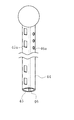
- FIG. 5 is a bottom view of the transanal drain device shown in FIG. 4. It is a schematic explanatory drawing which shows the state with which the transanal drain apparatus shown in FIG. 4 was mounted
- FIG. 1st drain tube shown in FIG. It is a cross-sectional view of the 1st drain tube shown in FIG. It is a perspective view of the transanal drain apparatus which concerns on 3rd Embodiment. It is a top view which shows the approach prevention member of FIG. It is a fragmentary sectional view which shows the use condition of the transanal drain apparatus shown in FIG. It is a fragmentary sectional view which shows the use condition of the transanal drain apparatus which concerns on other embodiment. It is a half sectional view which shows the approach prevention member of the transanal drain apparatus which concerns on other embodiment. It is a schematic explanatory drawing which shows the transanal drain apparatus which concerns on other embodiment. It is a schematic explanatory drawing which shows the transanal drain apparatus which concerns on other embodiment. It is a schematic explanatory drawing which shows the transanal drain apparatus which concerns on other embodiment. It is a perspective view which shows the transanal drain apparatus which concerns on other embodiment. It is front sectional drawing of FIG. It is a partially broken perspective
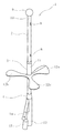
- FIG. 1 shows a transanal drain device (hereinafter referred to as “drain device”) 1 according to a first embodiment, which is an example of a body tube device.
- the drain device 1 includes a passage member 2, an entry preventing member 3 attached to the outer periphery of the passage member 2, and a connection member 4 connected to the lower end portion of the passage member 2.
- the passage member 2 has a hollow cylindrical shape, is made of a material such as flexible silicon rubber, and can be formed by extrusion molding.
- a second passage portion 6 and a third passage portion 7 are formed on the outer peripheral wall (wall portion) in addition to the first passage portion 5 that is the internal space thereof.
- the first passage portion 5 is configured by a hole having a circular cross section formed eccentrically from the axial center position of the passage member 2. For this reason, the wall thickness of the outer peripheral wall of the passage member 2 is different in the circumferential direction. And the 2nd channel
- path part 6 is an elongate hole, and is provided in two places along the circumferential direction here.
- the third passage portion 7 is a hole having a smaller channel cross-sectional area than the second passage portion 6.
- the first through hole 8 (see FIG. 2) is provided on the outer peripheral wall of the passage member 2 at two positions by shifting the positions in the circumferential direction and the axial direction on the front end side and the rear end side, respectively. 2 (a) shows only one of them).
- Each first through-hole 8 communicates with the first passage portion 5 and is formed to a size that allows water-like feces in the intestine to pass therethrough and be guided into the first passage portion 5.
- a spherical bulge 9 is formed at the tip of the passage member 2.
- the third passage portion 7 communicates with the bulging portion 9 and can be elastically expanded by supplying water from a connecting member 4 described later.
- a plurality (four in this case) of second through holes 10 are formed between the bulge portion 9 and the first through hole 8 on the distal end side.
- the second through hole 10 communicates with the second passage portion 6 formed on the outer peripheral wall of the passage member 2 and is formed in a size that makes it difficult for watery feces to flow in.
- the 2nd through-hole 10 is covered with a waterproof breathable material, the size and shape of the 2nd through-hole 10 can be freely set.
- the second through hole 10 is arranged upstream of the suture position in the rectum (near the sigmoid colon) (this position is also a position where it is difficult to soak in the watery stool collected in the rectum).
- the length inserted into the intestinal tract of the passage member 2 is in the range of 50 mm to 250 mm.
- the entry blocking member 3 is made of an elastic material (for example, a rubber material), and as shown in FIG. 1, a hollow cylindrical mounting portion 11 fixed to the outer periphery of the passage member 2 and a base portion of the mounting portion 11 to the side. It is provided with the approach prevention part 12 (entrance prevention piece 12a, 12b, 12c) extended.
- an elastic material for example, a rubber material
- the lower end of the passage member 2 is inserted into the mounting portion 11 from above and protrudes from below.
- the mounting portion 11 and the passage member 2 are bonded together to form an integral structure.
- An upper end portion of a connection member 4 to be described later is inserted into the lower end portion of the passage member 2, and these are connected by adhesion or the like.
- the outer diameter dimension of the mounting portion 11 is set to a value that facilitates insertion into the anus (for example, a diameter of 11 mm), and is the same as or slightly longer than the anal canal.
- the length of the anal canal varies from person to person, but the length of the mounting portion 11 is determined to be slightly longer (45 mm in this case) than the length assumed by the Japanese (about 30 mm to about 40 mm). ing.
- Each entry blocking piece 12a, 12b, 12c has a width dimension that gradually increases toward the tip in a plan view, and is formed in an arc shape at the tip.
- the entry blocking piece 12a has a cross-sectional mountain shape in accordance with the shape of the crotch.
- the entry blocking pieces 12b, 12c are formed thin, elastically deformed along the inner crotch with the entry blocking piece 12a disposed between the crotch, and can be fixed to the inner crotch with an adhesive applied to the surface thereof.
- the entry blocking piece 12a can also be fixed to the body side with an adhesive.
- the connecting member 4 includes a first passage portion 13, and a second passage portion 14 and a third passage portion 15 that extend obliquely from the tip portion.
- the outer surface of the upper end portion of the connection member 4 is formed in a conical shape and is connected to the passage member 2.
- the first passage portion 13, the second passage portion 14, and the third passage portion 15 are communicated with the first passage portion 5, the second passage portion 6, and the third passage portion 7 of the passage member 2, respectively.
- a tube or the like (not shown) is connected to the first passage portion 13 so that the discharged watery stool is discharged to a bag body (not shown).
- the second passage portion 14 is used as it is, and discharges the gas that has passed through the second passage portion 6 from the second through hole 10 of the passage member 2.
- the third passage portion 15 includes a check valve (not shown) inside. When the check valve is pressed by a syringe or the like, the flow path is opened and fluid (here, water) is allowed to flow in and out.
- the internal space of the passage member 2 is constituted by the first passage portion 5, and the second passage portion 6 is formed on the outer peripheral wall thereof.
- path member 2 can be set as the slim structure with a small outer diameter dimension, and it becomes possible to insert smoothly from an anus into an intestine.
- the burden on the patient can be reduced.
- the processing of the passage portions 5 and 6 has a simple configuration that can be integrally formed by extrusion molding.
- the drain device 1 having the above-described configuration is used for rectal resection (high anterior resection, low anterior resection, ultra-low anterior resection, intersphincter resection, etc.) performed while preserving the anus with colon cancer. Used when decompression is required.
- rectal resection high anterior resection, low anterior resection, ultra-low anterior resection, intersphincter resection, etc.
- the tip of the passage member 2 is inserted into the anus.
- the bulging portion 9 does not bulge and is kept in a small spherical shape. Thereby, insertion into an anus can be performed smoothly.
- the insertion part 11 is inserted into the anus, and the entry blocking piece 12a is arranged from the anus to the crotch on the rear side.
- the entry blocking pieces 12b and 12c are elastically deformed to follow the inner crotch and are fixed to the inner crotch with an adhesive.
- the entry blocking member 3 prevents the passage member 2 from further entering the intestine. Accordingly, the distal end portion of the passage member 2, particularly the position of the second through-hole 10, can be disposed at a desired position, that is, at a position on the back side of the rectal suture portion.
- a syringe (specifically, a distal end cylinder portion on which the syringe needle of the syringe is not attached) is inserted into the third passage portion 15, and water is injected to inflate the bulge portion 9 with the check valve opened.
- the check valve closes the flow path, and the bulging portion 9 maintains the bulging state.
- the bulging portion 9 has a spherical shape and no corner portion, and this portion contacts the intestinal wall. Moreover, the contact area is sufficiently large. Therefore, there is no worry that the pressure is increased and damaged in a part of the intestinal wall.
- the transanal drain device it is only necessary to fix the entry blocking pieces 12b and 12c (in some cases, the entry blocking piece 12a) to the inner crotch, so that the burden on the patient in the attached state is small. Further, the watery stool near the anus that tends to stay can be discharged from the first through hole 8 of the passage member 2 through the first passage portion 5. Further, regardless of the discharge state of the watery stool, the gas generated in the intestine can be discharged through the second passage portion 6 from the second through hole 10 formed on the distal end side of the passage member 2. Since the second through-hole 10 is formed on the deeper side of the intestine than the position where the watery stool near the anus is stored, the gas can be discharged smoothly. As a result, it is possible to prevent the occurrence of a problem that the gas pressure in the intestine increases and the anastomosis portion opens.
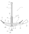
- FIG. 4 shows a drain device 1 according to the second embodiment, which is another example of the body tube device.
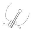
- the drain device 1 includes a drain body 16 that is an example of a first passage member, and a first drain tube 17 that is an example of a second passage member that is attached to the drain body 16.
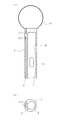
- the drain main body 16 is made of an elastic material (for example, a rubber material), and includes a mounting portion 18 that is inserted into the anus and an entry blocking portion 19 that extends forward and backward from the lower end of the mounting portion 18.
- an elastic material for example, a rubber material
- the mounting portion 18 has a hollow cylindrical shape, and its outer diameter, inner diameter, and length are set in the same manner as in the first embodiment.
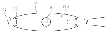
- the entry preventing portion 19 has a substantially elliptical shape in plan view, and the upper surface 19a from which the mounting portion 18 protrudes is formed in a cross-sectional mountain shape according to the shape of the crotch, and as it goes toward both ends. It gradually curves upward.
- the two sides of the upper surface 19a are formed in an R shape so that an acute angle structure is not exposed at the contact portion with the body.
- the lower surface 19b is curved in the same manner as the upper surface 19a. However, the radius of curvature is set smaller than that of the upper surface, and the entry preventing portion 19 is gradually thinner toward both ends.
- first communication hole 20 passes through the mounting portion 18 and the entry preventing portion 19.
- the first communication hole 20 opens in the lower surface 19b of the entry blocking portion 19, and a relief recess 21 having an enlarged inner diameter is formed there.
- a non-slip portion 22 (or formed of a plurality of annular grooves) is formed in a predetermined range (a range from the second communication hole 23 below) from the escape recess 21. ing.
- the second communication hole 23 is branched from the middle of the first communication hole 20.
- the second communication hole 23 extends orthogonally to the first communication hole 20 and opens at a side portion of the lower surface 19b.
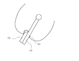
- One end of the second drain tube 24 is connected to this opening.
- the second drain tube 24 is made of vinyl chloride or the like.
- the other end of the second drain tube 24 is connected to a bag body (not shown, but, for example, a urobag or the like can be used) via a joint portion 25.
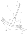
- FIG. 8 shows a state in which the drain device 1 using the strip 27 is mounted.
- the belt-like body 27 includes the first belt-like portion 28a and the second belt-like portion 28b in which the drain device 1 (only the entry preventing portion 19 is shown in FIG. 8) is divided into two in front of the body, and the third belt-like shape in the rear.
- a part 28c and a fourth belt part 28d wound around the waist and connected to the first to third belt parts 28a to 28c are configured. Thereby, the approach prevention part 19 can be fixed to a patient's body, without adhere
- the first drain tube 17 is made of a material such as flexible silicon rubber.
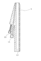
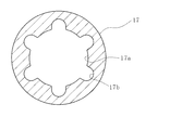
- a structure is adopted in which a groove portion 17b having an arc-shaped cross section along the longitudinal direction is formed in six equal portions in the circumferential direction on the inner peripheral surface constituting the center hole 17a. According to this structure, the path is not completely blocked even if it is crushed from any direction around the first drain tube 17.
- the first drain tube 17 is inserted into the first communication hole 20 of the drain main body 16, and one end thereof is located in the escape recess 21 of the entry blocking portion 19.
- a hollow plug 29 is attached to one end (base) of the first drain tube 17.
- the hollow plug body 29 has a cylindrical shape having a flange portion 29 a and is press-fitted into one end portion of the first drain tube 17, and the one end portion is sandwiched between the non-slip portion 22 formed in the first communication hole 20.
- the lower end part of the 1st communicating hole 20 is closed, and the 1st path
- the first drain tube 17 is positioned with respect to the drain body 16. In this state, the flange portion 29 a of the hollow plug body 29 is located in the escape recess 21 and does not protrude from the lower surface 19 b of the entry blocking portion 19.
- the protruding dimension of the drain body 16 from the mounting portion 18 is determined in consideration of the position of the distal end portion (the other end side) in the rectum, as in the first embodiment. is there.
- the protrusion dimension of the drain tube 17 from the drain main body 16 can be adjusted as needed. For example, one end of the first drain tube 17 may be cut to a desired length, and then fixed to the drain body 16 by the hollow plug body 29.
- a spherical bulge 30 is formed at the other end (tip) of the first drain tube 17. Since the bulging part 30 is spherical, there is little friction with the intestinal wall, and it can be smoothly inserted into and removed from the rectum. Further, after insertion, since the bulging portion 30 has no corners and has a large contact area with the intestinal wall, the pressure does not partially increase and the intestinal wall is not damaged.
- each through-hole 31 is set to a value that is sufficiently small and difficult for watery stools to flow, at least smaller than the inner diameter of the first drain tube itself.
- gas generated mainly in the intestine can be discharged.
- the through hole 31 is not formed in the bulging portion 9 and the inner diameter dimension thereof is sufficiently small so that the watery stool is difficult to flow in.
- the inner diameter of the first drain tube 17 is formed larger than the through-hole 31, so that it is smoothly discharged without causing clogging. Can do.
- annular passage 32 for discharging watery feces is formed between the outer peripheral surface of the first drain tube 17 and the inner peripheral surface of the first communication hole 20 of the entry preventing member 3. Even if the first drain tube 17 is made of a material having flexibility and is bent in use and a part of the annular passage 32 may be closed, the first drain tube 17 must be moved to the second drain tube 24 in any of the surroundings. Can be secured.
- first drain tube 17 and the second drain tube 24 with a pump or a bag that generates a negative pressure so that gas or watery stool can be forcibly discharged.
- the mounting portion 18 of the drain body 16 is inserted into the anus.
- a first drain tube 17, a second drain tube 24, and a strip 27 are connected to the drain body 16 in advance.
- One end of the first drain tube 17 is inserted from the opening of the mounting portion 18 and is positioned in the first communication hole 20 of the entry blocking portion 19.
- the hollow plug body 29 is press-fitted into one end opening of the first drain tube 17, and the first drain tube 17 is sandwiched between the non-slip portion 22 and positioned.
- the belt-like bodies 27 are respectively attached to the long holes 26 of the entry blocking portion 19.
- the first drain tube 17 may be mounted after the mounting portion 18 of the drain main body 16 is inserted into the anus, or the first drain tube 17 is inserted into the anus first.
- the mounting portion 18 of the main body 16 may be inserted into the anus.
- the order of attachment to the anus can be freely changed according to the use situation.
- the mounting portion 18 of the drain main body 16 is inserted until the upper surface of the entry preventing portion 19 is located along the crotch. In this state, the tip position of the mounting portion 18 reaches the same position as the upper edge of the anal canal or a position slightly beyond it. As a result, the annular passage 32 opens to a portion near the upper portion of the anal canal in the rectum, and the watery feces can be discharged through the annular passage 32.
- the first drain tube 17 has the bulging portion 30 at the tip positioned behind the anastomosis portion of the rectum. This may be determined in consideration of the length of the rectal portion of the patient after surgery (mainly the anastomosis position). Even after the mounting, the insertion position of the first drain tube 17 can be adjusted.
- the belt-like body 27 is used by appropriately wrapping around the trunk or thigh of the body. Thereby, the attachment state of the drain main body 16, the 1st drain tube 17, and the 2nd drain tube 24 can be stabilized.
- the bulging portion 30 is formed at the distal end portion of the first drain tube 17.
- the bulging portion 30 has a spherical shape and no corners. Therefore, as in the first embodiment, the distal end portion of the first drain tube 17 does not damage the intestinal wall.
- the watery stool that has flowed through the intestine does not directly enter the first drain tube. Then, mainly gas in the intestine flows through the first drain tube 17 through the through hole 31 formed in the vicinity of the bulging portion 30 and is discharged outside the body. Since gas is mainly discharged through the first drain tube 17, the first drain tube 17 can always be kept in communication with the outside of the body. Therefore, it is sufficient for the patient to put on a disposable diaper after wearing the drain device 1. Since the watery stool is hardly discharged, the paper diaper is hardly contaminated to cause problems such as rough skin.
- the mounting portion 18 of the drain main body 16 is located in the vicinity of the upper edge of the anal canal in the rectum, and an annular passage 32 formed between the first drain tube 17 disposed inside thereof opens.
- the anal canal is in close contact with the outer peripheral surface of the mounting portion 18 so that watery stool does not leak out. Watery stool accumulates in the rectum before the anal canal and is discharged from the annular passage 32 to the bag body via the second drain tube 24.
- the second drain tube 24 is connected to a side portion of the lower surface 19b of the drain body 16. For this reason, the second drain tube 24 can be arranged along the lower surface 19b without being bent. As a result, there are few protrusion parts from the drain main body 16, and even if it wears a paper diaper, it does not become obstructive. In other words, gas and watery feces can be discharged smoothly while the wearing state is stabilized, and the burden on the patient can be suppressed.
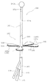
- FIG. 10 shows a drain device 100 according to the third embodiment, which is another example of the body tube device.
- the drain device 1 includes a passage member 101 that is a tube, and an entry prevention member 102 and a connection member 103 that are attached to the passage member 101.
- the passage member 101 has substantially the same configuration as the passage member 2 of the first embodiment.
- the passage member 101 has a hollow cylindrical shape, is made of a flexible material such as silicon rubber, and can be formed by extrusion molding.
- the passage member 101 is formed with a second passage portion and a third passage portion on the outer peripheral wall (wall portion) in addition to the first passage portion which is the internal space (see FIG. 3).
- a plurality of first through holes 101a are formed in the outer peripheral wall of the passage member at predetermined intervals along the longitudinal direction. Each first through-hole 101a communicates with the first passage portion, and can pass watery stool in the intestine and guide it into the first passage portion.
- a spherical bulge 101 b is formed at the tip of the passage member 101.
- the third passage portion communicates with the bulging portion 101b, and can be inflated elastically by supplying water.
- a plurality (four in this case) of second through holes 101c are formed in the vicinity of the bulging portion 101b.
- the second through-hole 101c communicates with the second passage portion formed on the outer peripheral wall of the passage member 101, but is formed in such a size that the watery stool is difficult to flow in and the gas mainly flows.
- the entry blocking member 102 is made of an elastic material (for example, a rubber material), and has a hollow cylindrical mounting portion 104 that is fixed to the outer periphery of the passage member 2 and an entry blocking portion 105 that extends laterally from the base of the mounting portion 104. Is provided.
- the mounting part 104 is also a part constituting the guide part of the present invention.
- the mounting part 104 has the same configuration as that of the mounting part 11 according to the first embodiment, and the outer diameter dimension and length are similarly designed.
- the adhesive layer 106 is formed by applying an adhesive between the inner peripheral surface of the mounting portion 104 and the outer peripheral surface of the passage member 102, so that both members are integrated. Further, the protruding dimension of the mounting portion 104 from the entry blocking portion 105, that is, the insertion length into the body, is designed to be substantially the same as that of the patient's anal canal, as in the above-described embodiment.
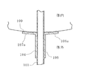
- the entry blocking unit 105 includes a first blocking piece pair 107 and a second blocking piece pair 108 that are arranged in line symmetry with respect to a straight line L1 passing through the axis within a plane orthogonal to the axis of the mounting unit 104.
- the first blocking piece pair 107 includes two first blocking pieces 107a
- the second blocking piece pair 108 includes two second blocking pieces 108a.
- the first blocking piece 107a and the second blocking piece 108a are thin and gradually increase in width as they move away from the mounting portion, and the tip edge is formed in an arc shape and rounded.
- the opposing edges of the first blocking piece 107a are close to each other so that a substantially uniform narrow gap is formed.
- the second blocking pieces 108a are arranged such that the center lines L2 form an angle of about 120 ° with respect to the center line L1 of the gap between the first blocking pieces 107a. That is, the interval between the first blocking pieces 107a is narrower than the interval between the second blocking pieces 108a.
- the length of the first blocking piece 107a from the mounting portion 104 is longer than that of the second blocking piece 108a.
- An adhesive is applied to one side of the first blocking piece 107a and the second blocking piece 108a (the surface on the side of the mounting portion 104 entering the body) to form an adhesive layer 109.
- These adhesive layers 109 are each covered with a release sheet 110.
- the release sheet 110 can be easily peeled off during use.
- the connection member 103 includes a first passage portion 113, and a second passage portion 114 and a third passage portion 115 extending obliquely from the front end portion thereof, as in the above embodiment.
- the outer surface of the upper end portion of the connection member 4 is formed in a conical shape and is connected to the passage member 2.
- path part 113 is connected to the 1st channel
- the second passage portion 114 is connected to the second passage portion of the passage member 101, and discharges the gas that has passed through the second passage portion from the second through hole 101 c of the passage member 101.
- the third passage portion 115 is connected to the third passage portion, and an internal check valve (not shown) is pressed by a syringe or the like to open the flow path, so that fluid (here, water) flows in and out. Is acceptable.
- the passage member 101 and then the mounting portion 104 are inserted into the anus, and the release sheet 110 is sequentially peeled off from each first blocking piece 107a and attached to the inner crotch. Subsequently, the release sheet 110 is sequentially peeled off from each of the second blocking pieces 108a and attached to the collar portion.
- work of the drain apparatus 100 to a body can be completed. Since each of the blocking pieces 107a and 108a can be peeled off and attached to the body in order, the sticking operation can be performed one by one. At the time when the mounting operation is completed, as shown in FIG.
- each of the blocking pieces 107a and 108a has elasticity, can be flexibly deformed according to the shape of the periphery of the anus, and can be attached in an appropriate state. Therefore, there is little burden on the body and no pain or the like is caused in the anus.
- the mounting portion 104 has almost the same length as the anal canal, but may have a short dimension that guides only the anal portion. Moreover, the mounting part 104 is good also as a structure which eliminated the part inserted in an anus and extended to the part located in the other side of the approach prevention part 105, ie, a body outer side. For example, as shown in FIG. 13, if the mounting portion 104 is formed on the outside of the body with respect to the entry blocking portion 105, the adhesive layer 106 between the outer peripheral surface of the passage member 101 and the inner peripheral surface of the mounting portion 104 can be reliably secured. It can be formed outside the body.
- the mounting portion 104 can be integrated with different lengths of the passage member 101 protruding therefrom.
- the protrusion dimension of the passage member 101 from the mounting part 104 can be set to an appropriate length while looking at the display part, and the protrusion dimension can be grasped at a glance after manufacture.
- the mounting portion 104 can be configured such that the opening cross-sectional area in the axial direction changes.
- the mounting section 104 is configured such that the opening cross-sectional area (inner diameter dimension) gradually decreases as it moves away from the entry blocking section 105, the outer diameter dimension differs by cutting in the middle.
- the passage member 101 can be flexibly accommodated.
- the display part 104a which consists of a number which shows an opening cross-sectional area (inner diameter dimension) with the scale on the surface. Based on the outer diameter dimension of the passage member 101 to be used, the user only has to cut the mounting portion 104 at an appropriate location while viewing the display portion 104a.
- the passage member 101 may be integrated with the mounting portion 104 in the manufacturing stage in advance, or may be configured to be integrated at the time of use.
- the passage member 101 and the mounting portion 104 are not only an adhesive, but also those that simply use the pressure contact force or frictional force between the contact surfaces of both members, or those in which the surfaces of both members are connected with an adhesive tape or the like. It is also possible to adopt.
- a drain device for inserting gas from the anus and discharging intestinal gas or water stool is described as an example of a body tube device.
- a similar configuration can be employed.
- catheters include those that discharge body fluids and blood from the body, can supply chemicals, contrast agents, etc., can insert guide wires, stents, etc., and can perform both .
- the tube includes one that is used by being pierced in the skin and inserted into the body, or inserted from a body part that is already open, such as the oral cavity.
- a plurality of through holes 10 and 31 are formed in the other end of the passage member 2 and the first drain tube 17, and gas in the intestine is discharged through these through holes 10 and 31.
- a waterproof breathable material for example, Gore-Tex (registered trademark), breathable sheet (Breslon (registered trademark), etc.
- Gore-Tex registered trademark
- breathable sheet breathable sheet
- the entire first drain tube 17 need not be made of a waterproof and breathable material.
- An opening larger than the through holes 10 and 31 is formed at the other end, and the opening is made of a film made of a waterproof and breathable material. Fortress It may be so.
- water is supplied to the bulging portion 9 of the passage member 2.
- a balloon that floats on watery stool by supplying air may be used.
- the swelling part 30 of the 1st drain tube 17 shall have the characteristic only in the shape, you may comprise with the balloon which inflates by supplying air like the above.
- the through hole or the like can be prevented from being submerged in watery stool, and gas can be reliably supplied. This is preferable in that it can be discharged.
- the length of the mounting portions 11, 18, and 104 can be adjusted.
- the mounting portions 11, 18, and 104 may be screwed to the entry blocking portions 12, 19, and 105, and the protruding position may be adjusted by changing the screwing position.
- the protrusion dimension of mounting part 11, 18, 104 can be made into the suitable length according to the length of a patient's anal canal.
- the bulging portions 9, 30, 101b are formed at the distal ends of the passage member 2, the first drain tube 17, and the passage member 101, respectively, but these bulging portions 9, 30, 101b are formed in the drain device 1.
- the present invention is not limited to 100, and can be used for other tubes such as other drain tubes and catheters that are inserted into the body.
- the tube that is inserted into the body for use A tube body; A bulging portion having a curved surface as a contact portion with an in-vivo mounting site provided at the distal end of the tube body on the insertion side; With The tube body includes a communication portion that can supply or discharge a fluid from outside the body and expand or contract the bulge portion.
- This configuration makes it difficult for the insertion work to be hindered by reducing the bulge 9 when inserted into the body. Moreover, if a fluid is supplied into the bulging part via the communicating part and then inflated after insertion into the body, the inner wall of the mounting site in the body will not be damaged.
- the tube body preferably has the communication part formed on a cylindrical wall.
- This configuration allows the bulging portion to expand or contract without increasing the outer diameter of the tube.
- the drainage device 1 is fixed by winding the belt-like body 27 around a part of the body (for example, the thigh or the torso).
- the drainage device 1 is appropriately fixed by other means such as a tape. You may do it.
- a double-pipe structure including the mounting portion 18 of the drain main body 16 and the first drain tube 17 is used.
- two drain tubes may be arranged side by side.
- a gap may be formed in the anus. Therefore, it is preferable that at least one of the tubes has flexibility. Thereby, the drain tube is pressed and deformed by the anal canal, and the generation of a gap can be prevented.
- the drain tube needs to maintain rigidity so as to ensure a flow path cross-sectional area through which gas and watery feces can flow.
- the mounting portion 18 of the drain main body 16 and the first drain tube 17 have a double pipe structure, and the annular passage 32 is formed between them. As shown in FIG.
- a non-annular passage may be formed.
- the first passage member is constituted by the drain main body 16 and the second passage member is constituted by the first drain tube 17.
- a cylindrical guide sleeve 35 may be provided on the outer periphery of two drain tubes 33 and 34 having different sizes, and the guide sleeve 35 may be held by an anal canal.
- the drain tubes 33 and 34 may be configured so as to be arranged without a gap on the inner periphery of the guide sleeve 35.
- at least one of the drain tubes 33 and 34 is made of a flexible material, or a sealing member (not shown) is interposed between the drain tubes 33 and 34 and the guide sleeve 35. It may be.
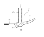
- the drain main body 16 is configured as shown in FIG. 4 and the like, but may be configured as follows.
- the drain main body 16 includes a main body portion 36, a mounting portion 37 that extends upward from the main body portion 36, and entry blocking portions 38, 39, and 40 that are divided into three forks from the main body portion 36.
- the entry blocking part 38 is formed in a cross-sectional mountain shape as in the above-described embodiment, and extends rearward from the anus according to the shape of the crotch.
- the entry blocking portions 39 and 40 are formed thin, elastically deformed along the inner crotch and fixed to the inner crotch with tape or the like as shown by a two-dot chain line in FIG. 17 with the entry blocking portion 38 disposed between the crotch. It can be done.
- the entry preventing portion 38 can be fixed to the body side with a tape or the like. In addition, you may comprise so that it can fix to the body side by apply
- a central hole 41 is formed in the mounting portion 37, and a first communication hole 42 and a second communication hole 43 communicating with the central hole 41 are formed in the main body portion 36.
- the first communication hole 42 has a diameter smaller than that of the center hole 41, is arranged on the same straight line as the center hole 41, and forms a stepped hole that opens on the lower surface of the main body 36.
- the second communication hole 43 diverges obliquely downward from the center hole 41 and constitutes a stepped hole that opens on an inclined surface formed on the lower side between the entry blocking portions 39 and 40.
- the first drain tube 17 is disposed in the center hole 41 of the mounting portion 37 through the first communication hole 42.
- the first drain tube 17 is fixed between the outer peripheral surface of the hollow plug body 29 whose front end portion protrudes from the mounting portion 37 and the rear end portion is press-fitted into the first communication hole 42 and the inner peripheral surface of the first communication hole 42. Is done. Watery feces in the intestine can be discharged through an annular passage 32 formed between the inner peripheral surface of the mounting portion 37 and the inner peripheral surface of the first drain tube 17.
- the second drain tube 24 is connected to the second communication hole 43 so that the watery stool can be discharged into the bag body.
- the transanal drain device having the above-described configuration, it is not necessary to sew on the body as in the conventional case, and the occurrence of pain associated with the suturing can be prevented.
- the transanal drain device since it is only necessary to attach the entry preventing portions 39 and 40 to the inner crotch with a tape or the like, the transanal drain device can be easily fixed to the body.
- there is little risk of displacement in use as in the case of fixing with a string.
- replacement or the like can be easily performed only by removing the tape.
- the first drain tube 17 is disposed in the mounting portion 37 as in the second embodiment.
- the trans-anal drain device can be configured by only the mounting portion 37. . In this case, either the first communication hole 42 or the second communication hole 43 is not necessary.
Landscapes
- Health & Medical Sciences (AREA)
- Heart & Thoracic Surgery (AREA)
- Vascular Medicine (AREA)
- Engineering & Computer Science (AREA)
- Anesthesiology (AREA)
- Biomedical Technology (AREA)
- Hematology (AREA)
- Life Sciences & Earth Sciences (AREA)
- Animal Behavior & Ethology (AREA)
- General Health & Medical Sciences (AREA)
- Public Health (AREA)
- Veterinary Medicine (AREA)
- Infusion, Injection, And Reservoir Apparatuses (AREA)
Abstract
La présente invention aborde le problème de la conception d'un élément bloqueur de pénétration qui soit facile à installer, ait un impact réduit sur le corps après installation et présente une excellente stabilité. L'invention concerne un élément bloqueur de pénétration pourvu d'un segment d'installation tubulaire (104), qui est ajusté sur la surface circonférentielle d'un tube (101) destiné à être inséré dans un corps, et d'une partie de blocage de pénétration (105) qui est intégrée au segment d'installation (104) et qui est destinée à limiter la distance de pénétration du tube (101) dans le corps. La partie de blocage de pénétration (105) s'étend du segment d'installation (104) dans la direction radiale et est formée de plusieurs pièces de blocage de pénétration (104a, 105a) élastiques.
Applications Claiming Priority (4)
| Application Number | Priority Date | Filing Date | Title |
|---|---|---|---|
| JP2015071515 | 2015-03-31 | ||
| JP2015-071515 | 2015-03-31 | ||
| JP2015140648A JP6042948B2 (ja) | 2015-03-31 | 2015-07-14 | 経肛門ドレーン装置 |
| JP2015-140648 | 2015-07-14 |
Publications (1)
| Publication Number | Publication Date |
|---|---|
| WO2016159272A1 true WO2016159272A1 (fr) | 2016-10-06 |
Family
ID=57004383
Family Applications (1)
| Application Number | Title | Priority Date | Filing Date |
|---|---|---|---|
| PCT/JP2016/060754 Ceased WO2016159272A1 (fr) | 2015-03-31 | 2016-03-31 | Élément bloqueur de pénétration et dispositif tube somatique |
Country Status (1)
| Country | Link |
|---|---|
| WO (1) | WO2016159272A1 (fr) |
Citations (8)
| Publication number | Priority date | Publication date | Assignee | Title |
|---|---|---|---|---|
| JP2002508212A (ja) * | 1997-12-17 | 2002-03-19 | アストラゼネカ アクツィエボラーグ | 医療装置 |
| JP2006223704A (ja) * | 2005-02-21 | 2006-08-31 | Shigenobu Takane | 排便器具 |
| JP2009291632A (ja) * | 2009-08-06 | 2009-12-17 | Hollister Inc | 改良された人工肛門装置 |
| JP2012530519A (ja) * | 2009-06-18 | 2012-12-06 | デパートメント オブ バイオテクノロジー | 失禁患者における便排出物を収集するための装置 |
| WO2013181686A1 (fr) * | 2012-06-03 | 2013-12-12 | Daniel Eduard Kleiner | Dispositif endoluminal de thérapie par le vide |
| JP2015116489A (ja) * | 2013-12-19 | 2015-06-25 | キョンプク ナショナル ユニバーシティ インダストリー−アカデミック コーポレーション ファウンデーション | 直腸吻合保護用装置 |
| JP2015181511A (ja) * | 2014-03-20 | 2015-10-22 | テルモ株式会社 | 医療用ドレーンチューブ |
| US20150328437A1 (en) * | 2014-05-19 | 2015-11-19 | Noureyah Rageh | Rectal tube securement device |
-
2016
- 2016-03-31 WO PCT/JP2016/060754 patent/WO2016159272A1/fr not_active Ceased
Patent Citations (8)
| Publication number | Priority date | Publication date | Assignee | Title |
|---|---|---|---|---|
| JP2002508212A (ja) * | 1997-12-17 | 2002-03-19 | アストラゼネカ アクツィエボラーグ | 医療装置 |
| JP2006223704A (ja) * | 2005-02-21 | 2006-08-31 | Shigenobu Takane | 排便器具 |
| JP2012530519A (ja) * | 2009-06-18 | 2012-12-06 | デパートメント オブ バイオテクノロジー | 失禁患者における便排出物を収集するための装置 |
| JP2009291632A (ja) * | 2009-08-06 | 2009-12-17 | Hollister Inc | 改良された人工肛門装置 |
| WO2013181686A1 (fr) * | 2012-06-03 | 2013-12-12 | Daniel Eduard Kleiner | Dispositif endoluminal de thérapie par le vide |
| JP2015116489A (ja) * | 2013-12-19 | 2015-06-25 | キョンプク ナショナル ユニバーシティ インダストリー−アカデミック コーポレーション ファウンデーション | 直腸吻合保護用装置 |
| JP2015181511A (ja) * | 2014-03-20 | 2015-10-22 | テルモ株式会社 | 医療用ドレーンチューブ |
| US20150328437A1 (en) * | 2014-05-19 | 2015-11-19 | Noureyah Rageh | Rectal tube securement device |
Similar Documents
| Publication | Publication Date | Title |
|---|---|---|
| US20250135152A1 (en) | Urinary catheter | |
| CN111902182B (zh) | 女用导管定位器末梢 | |
| US5941815A (en) | Sigmoid splint device for endoscopy | |
| ES2769645T3 (es) | Conjuntos de cartucho de catéter | |
| US8518020B2 (en) | Safety urinary catheter | |
| KR20020093109A (ko) | 뒤집힐 수 있는 슬리브가 구비된 카테터 o.t.l.용삽입기 장치 | |
| JP2016193190A (ja) | 進入阻止部材及び身体用チューブ装置 | |
| TW201726201A (zh) | 人工氣道裝置 | |
| JP2006507894A (ja) | 反転して取り付けられたバルーン部分を有するカテーテル | |
| JP2011506000A (ja) | 圧力制御バルーンカテーテル | |
| US20150182728A1 (en) | Catheter insertion site plug | |
| EP3582744B1 (fr) | Dispositif de gastrostomie pourvu d'un élément de retenue amélioré | |
| WO2020261591A1 (fr) | Cathéter à ballon | |
| JP6581513B2 (ja) | 医療用長尺体 | |
| JP2005103120A (ja) | バルーンカテーテル | |
| JP2014180386A (ja) | 胃瘻カテーテル用内視鏡 | |
| US9999412B2 (en) | Fistula management device and method | |
| KR101528418B1 (ko) | 체내 삽입용 도관 | |
| WO2016159272A1 (fr) | Élément bloqueur de pénétration et dispositif tube somatique | |
| ES3033285T3 (en) | Catheter assembly | |
| EP4044972B1 (fr) | Dispositif de collecte d'urine | |
| CN212416632U (zh) | 一种球囊扩张导管 | |
| JP2005013710A (ja) | 身体アクセスポート | |
| JP2020151139A (ja) | バルーンカテーテル | |
| CN113576387B (zh) | 一种胃镜辅助装置及其使用方法 |
Legal Events
| Date | Code | Title | Description |
|---|---|---|---|
| 121 | Ep: the epo has been informed by wipo that ep was designated in this application |
Ref document number: 16773152 Country of ref document: EP Kind code of ref document: A1 |
|
| NENP | Non-entry into the national phase |
Ref country code: DE |
|
| 122 | Ep: pct application non-entry in european phase |
Ref document number: 16773152 Country of ref document: EP Kind code of ref document: A1 |