WO2016167101A1 - Contenant et capuchon - Google Patents
Contenant et capuchon Download PDFInfo
- Publication number
- WO2016167101A1 WO2016167101A1 PCT/JP2016/059659 JP2016059659W WO2016167101A1 WO 2016167101 A1 WO2016167101 A1 WO 2016167101A1 JP 2016059659 W JP2016059659 W JP 2016059659W WO 2016167101 A1 WO2016167101 A1 WO 2016167101A1
- Authority
- WO
- WIPO (PCT)
- Prior art keywords
- container
- cap
- diameter
- wall surface
- mouth
- Prior art date
- Legal status (The legal status is an assumption and is not a legal conclusion. Google has not performed a legal analysis and makes no representation as to the accuracy of the status listed.)
- Ceased
Links
Images


Classifications
-
- B—PERFORMING OPERATIONS; TRANSPORTING
- B65—CONVEYING; PACKING; STORING; HANDLING THIN OR FILAMENTARY MATERIAL
- B65D—CONTAINERS FOR STORAGE OR TRANSPORT OF ARTICLES OR MATERIALS, e.g. BAGS, BARRELS, BOTTLES, BOXES, CANS, CARTONS, CRATES, DRUMS, JARS, TANKS, HOPPERS, FORWARDING CONTAINERS; ACCESSORIES, CLOSURES, OR FITTINGS THEREFOR; PACKAGING ELEMENTS; PACKAGES
- B65D41/00—Caps, e.g. crown caps or crown seals, i.e. members having parts arranged for engagement with the external periphery of a neck or wall defining a pouring opening or discharge aperture; Protective cap-like covers for closure members, e.g. decorative covers of metal foil or paper
- B65D41/02—Caps or cap-like covers without lines of weakness, tearing strips, tags, or like opening or removal devices
- B65D41/28—Caps combined with stoppers
-
- B—PERFORMING OPERATIONS; TRANSPORTING
- B65—CONVEYING; PACKING; STORING; HANDLING THIN OR FILAMENTARY MATERIAL
- B65D—CONTAINERS FOR STORAGE OR TRANSPORT OF ARTICLES OR MATERIALS, e.g. BAGS, BARRELS, BOTTLES, BOXES, CANS, CARTONS, CRATES, DRUMS, JARS, TANKS, HOPPERS, FORWARDING CONTAINERS; ACCESSORIES, CLOSURES, OR FITTINGS THEREFOR; PACKAGING ELEMENTS; PACKAGES
- B65D47/00—Closures with filling and discharging, or with discharging, devices
- B65D47/04—Closures with discharging devices other than pumps
- B65D47/20—Closures with discharging devices other than pumps comprising hand-operated members for controlling discharge
- B65D47/2018—Closures with discharging devices other than pumps comprising hand-operated members for controlling discharge comprising a valve or like element which is opened or closed by deformation of the container or closure
- B65D47/2031—Closures with discharging devices other than pumps comprising hand-operated members for controlling discharge comprising a valve or like element which is opened or closed by deformation of the container or closure the element being formed by a slit, narrow opening or constrictable spout, the size of the outlet passage being able to be varied by increasing or decreasing the pressure
-
- B—PERFORMING OPERATIONS; TRANSPORTING
- B65—CONVEYING; PACKING; STORING; HANDLING THIN OR FILAMENTARY MATERIAL
- B65D—CONTAINERS FOR STORAGE OR TRANSPORT OF ARTICLES OR MATERIALS, e.g. BAGS, BARRELS, BOTTLES, BOXES, CANS, CARTONS, CRATES, DRUMS, JARS, TANKS, HOPPERS, FORWARDING CONTAINERS; ACCESSORIES, CLOSURES, OR FITTINGS THEREFOR; PACKAGING ELEMENTS; PACKAGES
- B65D41/00—Caps, e.g. crown caps or crown seals, i.e. members having parts arranged for engagement with the external periphery of a neck or wall defining a pouring opening or discharge aperture; Protective cap-like covers for closure members, e.g. decorative covers of metal foil or paper
- B65D41/02—Caps or cap-like covers without lines of weakness, tearing strips, tags, or like opening or removal devices
- B65D41/16—Snap-on caps or cap-like covers
- B65D41/18—Snap-on caps or cap-like covers non-metallic, e.g. made of paper or plastics
- B65D41/185—Snap-on caps or cap-like covers non-metallic, e.g. made of paper or plastics with integral internal sealing means
-
- B—PERFORMING OPERATIONS; TRANSPORTING
- B65—CONVEYING; PACKING; STORING; HANDLING THIN OR FILAMENTARY MATERIAL
- B65D—CONTAINERS FOR STORAGE OR TRANSPORT OF ARTICLES OR MATERIALS, e.g. BAGS, BARRELS, BOTTLES, BOXES, CANS, CARTONS, CRATES, DRUMS, JARS, TANKS, HOPPERS, FORWARDING CONTAINERS; ACCESSORIES, CLOSURES, OR FITTINGS THEREFOR; PACKAGING ELEMENTS; PACKAGES
- B65D47/00—Closures with filling and discharging, or with discharging, devices
- B65D47/04—Closures with discharging devices other than pumps
- B65D47/06—Closures with discharging devices other than pumps with pouring spouts or tubes; with discharge nozzles or passages
- B65D47/08—Closures with discharging devices other than pumps with pouring spouts or tubes; with discharge nozzles or passages having articulated or hinged closures
-
- B—PERFORMING OPERATIONS; TRANSPORTING
- B65—CONVEYING; PACKING; STORING; HANDLING THIN OR FILAMENTARY MATERIAL
- B65D—CONTAINERS FOR STORAGE OR TRANSPORT OF ARTICLES OR MATERIALS, e.g. BAGS, BARRELS, BOTTLES, BOXES, CANS, CARTONS, CRATES, DRUMS, JARS, TANKS, HOPPERS, FORWARDING CONTAINERS; ACCESSORIES, CLOSURES, OR FITTINGS THEREFOR; PACKAGING ELEMENTS; PACKAGES
- B65D47/00—Closures with filling and discharging, or with discharging, devices
- B65D47/04—Closures with discharging devices other than pumps
- B65D47/06—Closures with discharging devices other than pumps with pouring spouts or tubes; with discharge nozzles or passages
- B65D47/08—Closures with discharging devices other than pumps with pouring spouts or tubes; with discharge nozzles or passages having articulated or hinged closures
- B65D47/0857—Closures with discharging devices other than pumps with pouring spouts or tubes; with discharge nozzles or passages having articulated or hinged closures made separately from the base element provided with the spout or discharge passage
-
- B—PERFORMING OPERATIONS; TRANSPORTING
- B65—CONVEYING; PACKING; STORING; HANDLING THIN OR FILAMENTARY MATERIAL
- B65D—CONTAINERS FOR STORAGE OR TRANSPORT OF ARTICLES OR MATERIALS, e.g. BAGS, BARRELS, BOTTLES, BOXES, CANS, CARTONS, CRATES, DRUMS, JARS, TANKS, HOPPERS, FORWARDING CONTAINERS; ACCESSORIES, CLOSURES, OR FITTINGS THEREFOR; PACKAGING ELEMENTS; PACKAGES
- B65D47/00—Closures with filling and discharging, or with discharging, devices
- B65D47/04—Closures with discharging devices other than pumps
- B65D47/20—Closures with discharging devices other than pumps comprising hand-operated members for controlling discharge
- B65D47/2018—Closures with discharging devices other than pumps comprising hand-operated members for controlling discharge comprising a valve or like element which is opened or closed by deformation of the container or closure
-
- B—PERFORMING OPERATIONS; TRANSPORTING
- B65—CONVEYING; PACKING; STORING; HANDLING THIN OR FILAMENTARY MATERIAL
- B65D—CONTAINERS FOR STORAGE OR TRANSPORT OF ARTICLES OR MATERIALS, e.g. BAGS, BARRELS, BOTTLES, BOXES, CANS, CARTONS, CRATES, DRUMS, JARS, TANKS, HOPPERS, FORWARDING CONTAINERS; ACCESSORIES, CLOSURES, OR FITTINGS THEREFOR; PACKAGING ELEMENTS; PACKAGES
- B65D49/00—Arrangements or devices for preventing refilling of containers
- B65D49/02—One-way valves
-
- B—PERFORMING OPERATIONS; TRANSPORTING
- B65—CONVEYING; PACKING; STORING; HANDLING THIN OR FILAMENTARY MATERIAL
- B65D—CONTAINERS FOR STORAGE OR TRANSPORT OF ARTICLES OR MATERIALS, e.g. BAGS, BARRELS, BOTTLES, BOXES, CANS, CARTONS, CRATES, DRUMS, JARS, TANKS, HOPPERS, FORWARDING CONTAINERS; ACCESSORIES, CLOSURES, OR FITTINGS THEREFOR; PACKAGING ELEMENTS; PACKAGES
- B65D85/00—Containers, packaging elements or packages, specially adapted for particular articles or materials
- B65D85/70—Containers, packaging elements or packages, specially adapted for particular articles or materials for materials not otherwise provided for
- B65D85/72—Containers, packaging elements or packages, specially adapted for particular articles or materials for materials not otherwise provided for for edible or potable liquids, semiliquids, or plastic or pasty materials
-
- B—PERFORMING OPERATIONS; TRANSPORTING
- B05—SPRAYING OR ATOMISING IN GENERAL; APPLYING FLUENT MATERIALS TO SURFACES, IN GENERAL
- B05B—SPRAYING APPARATUS; ATOMISING APPARATUS; NOZZLES
- B05B11/00—Single-unit hand-held apparatus in which flow of contents is produced by the muscular force of the operator at the moment of use
- B05B11/0005—Components or details
- B05B11/0062—Outlet valves actuated by the pressure of the fluid to be sprayed
- B05B11/0072—A valve member forming part of an outlet opening
-
- B—PERFORMING OPERATIONS; TRANSPORTING
- B65—CONVEYING; PACKING; STORING; HANDLING THIN OR FILAMENTARY MATERIAL
- B65D—CONTAINERS FOR STORAGE OR TRANSPORT OF ARTICLES OR MATERIALS, e.g. BAGS, BARRELS, BOTTLES, BOXES, CANS, CARTONS, CRATES, DRUMS, JARS, TANKS, HOPPERS, FORWARDING CONTAINERS; ACCESSORIES, CLOSURES, OR FITTINGS THEREFOR; PACKAGING ELEMENTS; PACKAGES
- B65D47/00—Closures with filling and discharging, or with discharging, devices
- B65D47/04—Closures with discharging devices other than pumps
- B65D47/20—Closures with discharging devices other than pumps comprising hand-operated members for controlling discharge
- B65D47/2018—Closures with discharging devices other than pumps comprising hand-operated members for controlling discharge comprising a valve or like element which is opened or closed by deformation of the container or closure
- B65D47/2056—Closures with discharging devices other than pumps comprising hand-operated members for controlling discharge comprising a valve or like element which is opened or closed by deformation of the container or closure lift valve type
- B65D47/2081—Closures with discharging devices other than pumps comprising hand-operated members for controlling discharge comprising a valve or like element which is opened or closed by deformation of the container or closure lift valve type in which the deformation raises or lowers the valve port
Definitions
- the present invention relates to a container in which a cap molded from a synthetic resin is attached to a container mouth by a stopper or the like, and the cap.
- the width along the radial direction of the annular space of the cap is formed to be slightly narrower than the peripheral wall thickness of the container mouth portion, so that the body portion, the fitting wall portion, and the container mouth portion can The cap is attached to the container mouth by the pressing force.
- the outer diameter of the container mouth is substantially constant within a predetermined range along the axial direction, there is no problem with this prior art, but the container mouth has a plurality of mouths (steps) having different outer diameters as shafts.
- this prior art has a problem with the sealing performance between the container mouth and the cap.
- the container mouth portion is constituted by a plurality of mouth portions (step portions) having different outer diameters, simply by fitting the container mouth portion into the annular space provided in the cap, A problem arises in the sealing performance between the container mouth portion.
- the present invention has been made in view of such points, and even if a cap is attached to a container mouth portion constituted by a plurality of mouth portions (step portions) having different outer diameters by a stopper, the cap and the container mouth are provided. It aims at providing the container and cap which can ensure the sealing performance between parts.
- the present invention relates to a container according to claim 1, wherein the cap is mounted on the container mouth by plugging, and the container mouth is A large-diameter mouth portion disposed below the large-diameter mouth portion, and a small-diameter mouth portion having an outer diameter smaller than that of the large-diameter mouth portion, and the cap includes a trunk portion and a trunk portion.
- annular space provided between the cylindrical main fitting wall portion disposed on the inner side of the container and into which the container mouth portion is fitted, and a cylindrical sub-fitting wall portion formed in the annular space
- the inner wall surface of the sub-fitting wall portion of the cap and the outer wall surface of the large-diameter mouth portion of the container mouth portion are in close contact with each other
- the outer wall surface of the main fitting wall portion of the cap and the inner wall surface of the small-diameter mouth portion of the container mouth portion are in close contact with each other.
- the invention according to a second aspect is the invention according to the first aspect, wherein the container mouth portion has a diameter-increasing mouth portion that continuously and gradually expands downward from the small-diameter mouth portion,
- the container mouth portion has a diameter-increasing mouth portion that continuously and gradually expands downward from the small-diameter mouth portion
- the container is provided with a maximum diameter mouth portion continuously extending downward in the axial direction from the enlarged diameter mouth portion and having a larger diameter than the large diameter mouth portion.
- the maximum diameter mouth portion of the container mouth portion engages so as to get over the protrusion locking portion provided on the lower inner wall surface of the body portion of the cap.
- the diameter-enlarged mouth portion is elastically deformed so as to push up from below, so that the pressing force applied from the inner wall surface of the small-diameter mouth portion of the container mouth portion to the outer wall surface of the main fitting wall portion of the cap further increases.
- the sealing property between the outer wall surface of the main fitting wall portion of the cap and the inner wall surface of the small-diameter mouth portion of the container mouth portion can be further improved.
- the invention relating to the cap according to claim 3 is a cap that is attached to the container mouth by plugging, wherein the cap is a cylindrical main fitting wall portion disposed inside the barrel portion.
- a cap is provided.
- the main fitting of the cap from the inner wall surface of the container mouth portion is achieved by the close fitting wall portion formed in the annular space of the cap closely contacting the outer wall surface of the upper end of the container mouth portion.
- the pressing force to the outer wall surface of the wall portion is increased, and the sealing performance between the outer wall surface of the main fitting wall portion of the cap and the inner wall surface of the container mouth portion can be improved.
- the cap according to the third aspect wherein the main fitting wall portion integrally extends obliquely upward from the inner wall surface toward the radial center, and is formed at the radial central portion.
- the invention according to claim 5 is the invention according to claim 4, wherein the close contact portion between the outer wall surface of the main fitting wall portion and the inner wall surface of the container mouth portion is the main fitting.
- the sealing property between the cap and the container mouth portion is maintained.
- Containers and caps to be secured can be provided.
- FIG. 1 is a cross-sectional view showing a state where a cap is attached to a container mouth portion of a container according to an embodiment of the present invention.
- FIG. 2 is a cross-sectional view of the container mouth portion of FIG. 3 is a plan view of a main cap body including a lid body and an annular wall portion in the configuration of the cap of FIG. 1
- (b) is a cross-sectional view of (a)
- (c) is a bottom view.
- It is. 4A is a plan view of a check valve that is a configuration of the cap of FIG. 1
- FIG. 4B is a cross-sectional view of FIG. 4A
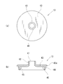
- FIG. Fig.5 (a) is a top view of the inner stopper which is a structure of the cap of FIG. 1, (b) is sectional drawing of (a).
- a container 1 includes a container body 1a and a cap 2 that is attached to the container opening 3 of the container body 1a by a stopper.
- the container main body 1a is easily deformable, such as a tube-shaped container, and the inside thereof is filled with a liquid content or a fluid content having viscosity.
- the contents include soy sauce, ponzu, olive oil, dressing, mayonnaise, ketchup, tonkatsu sauce, pasty mustard, and the like.
- the container main body 1a is of a type that discharges contents by applying an internal pressure by, for example, squeezing the body portion 7 thereof.
- the container mouth 3 is formed in a cylindrical shape.
- the container body 1a includes a double container (including a so-called peeling container) including an outer container and an inner container.
- the inner container is flexible so that it is filled with the contents and deforms as the contents decrease. In order to maintain the volume-reducing shape of the inner container, it is configured so that outside air is sucked between the outer container and the inner container.
- the container body 1 a includes a barrel portion 7 and a container mouth portion 3 that is continuously formed from the barrel portion 7 with the cap 2 fitted by a stopper.
- the container mouth part 3 is formed in a cylindrical shape as a whole.
- the container mouth portion 3 is continuously formed from the trunk portion 7 with substantially the same thickness.
- the container mouth portion 3 is configured by a plurality of mouth portions (step portions) having different outer diameters continuously along the axial direction. Specifically, the container mouth portion 3 is disposed at the upper end and extends in the axial direction, and is disposed below the large diameter mouth portion 60, and has an outer diameter smaller than that of the large diameter mouth portion 60.
- the large-diameter mouth portion 60 and the small-diameter mouth portion 61 positioned at the upper end are connected by an elastically deformable reduced-diameter mouth portion 63 that continuously decreases from the large-diameter mouth portion 60 downward.
- the small-diameter mouth portion 61 and the maximum-diameter mouth portion 62 are connected by an elastically deformable diameter-expanding mouth portion 64 that continuously expands downward from the small-diameter mouth portion 61.
- a support port 65 extending in the axial direction and having a diameter smaller than that of the maximum diameter port portion 62 and larger than that of the large diameter port portion 60 is continuously formed below the maximum diameter port portion 62.
- a concave port 66 having substantially the same diameter as the small-diameter port 61 is formed.
- the user operates the cap 2 by hand immediately after using the appropriate amount of contents by squeezing the body portion 7 of the container body 1a to apply internal pressure to the container body 1a.
- the inside of the container main body 1a is sealed by the check valve 12.
- the cap 2 includes a cap body 4 having a content discharge hole 25 and a lid connected to the main cap body 11 constituting the cap body 4 via a hinge 6. It is composed of a body 5.
- the present cap 2 has three configurations including a main cap body 11 to which the lid body 5 is connected and including the annular wall portion 10 shown in FIG. 3, a check valve 12 shown in FIG. 4, and an inner plug 13 shown in FIG. It is constructed by assembling members.
- the cap body 4 is integrally formed from a cylindrical main cap body 11 that is plugged into the container mouth portion 3 and an inner wall surface of the cylindrical main fitting wall portion 19 of the main cap body 11.
- An annular wall portion 10 extending obliquely upward toward the radial center and having a discharge hole 25 in the radial center portion, and disposed above the annular wall portion 10, and the valve portion 36 is an annular valve seat around the discharge hole 25.
- a check valve 12 that opens or closes the discharge hole 25 by being separated from or seated on the valve 26, and is disposed above the check valve 12, communicates with the discharge hole 25, and has a discharge passage 41 for contents from the discharge hole 25. It is comprised from the inside plug 13.
- the synthetic resin for molding the check valve 12 is more elastic than the synthetic resin for molding the main cap body 11.
- the main cap body 11 including the lid body 12 is formed of polypropylene.
- the inner plug 13 is formed of polyethylene.
- the check valve 12 is formed of a polyethylene elastomer.
- the main cap body 11 includes a body portion 18, a cylindrical main fitting wall portion 19 disposed concentrically inside the body portion 18, and an upper end of the body portion 18. It is comprised from the cyclic
- a protrusion locking portion 21 is formed on the lower inner wall surface of the body portion 18.
- An annular space 22 into which the container mouth 3 is fitted is formed between the cylindrical main fitting wall 19 and the trunk 18.
- An annular projecting portion 17 projecting upward is formed on the outer peripheral portion of the upper surface of the annular horizontal wall portion 20.
- An annular fitting recess 23 extending annularly along the circumferential direction is formed on the upper inner wall surface of the cylindrical main fitting wall portion 19.
- the annular wall portion 10 integrally extends obliquely upward from the entire circumferential direction toward the radial center.
- the annular wall portion 10 has a frustoconical shape.
- a space 24 having an open top is formed by the annular wall portion 10 and the inner wall surface of the cylindrical main fitting wall portion 19.
- a substantially circular discharge hole 25 is opened at the radial center of the annular wall 10.
- the discharge port 25 communicates with the inside of the container port 3.
- An annular valve seat 26 is formed around the discharge hole 25.
- the annular valve seat 26 is formed on an inverted conical surface 28.
- the annular valve seat 26 (inverted conical surface 28) of the annular wall portion 10 is formed with one flow groove 27 along the radial direction.
- the flow groove 27 is formed at a position opposite to the hinge 6 side.
- the flow groove 27 is formed in a U-shaped cross section.
- the outer diameter of the annular horizontal wall portion 20 is smaller than the outer diameter of the body portion 18, and a protrusion locking portion 31 that extends annularly along the circumferential direction is formed on the outer wall surface.
- the lid 5 is fitted to the outer wall surface of the annular horizontal wall portion 20.
- a cylindrical sub-fitting wall portion 32 is concentrically disposed in an annular space 22 between the body portion 18 and the cylindrical main fitting wall portion 19.
- a plurality of reinforcing ribs 33 are formed in the annular space between the cylindrical sub-fitting wall portion 32 and the body portion 18 at intervals along the circumferential direction. In this embodiment, eight places are formed.
- the rigidity of the cylindrical sub-fitting wall portion 32 can be maintained.
- the reason why the annular space is provided between the cylindrical sub-fitting wall portion 32 and the trunk portion 18 is that the annular space is not provided, and the cylindrical sub-fitting wall portion 32 is separated from the inner wall surface of the trunk portion 18. This is because if they are provided integrally, the wall becomes thick and problems such as sinking occur.
- the check valve 12 includes a cylindrical support portion 34 that contacts the inner wall surface of the cylindrical main fitting wall portion 19 of the main cap body 11, and an inner portion of the cylindrical support portion 34. Between the elastic pieces 35, a plurality of elastic pieces 35 that integrally extend from the wall surface toward the center in the radial direction, a valve portion 36 that is integrally connected to the tip of each elastic piece 35, and opens and closes the discharge hole 25. And a plurality of flow holes 37 through which the contents from the discharge holes 25 flow.
- Each elastic piece 35 extends from the upper inner wall surface of the cylindrical support portion 34 toward the center in the radial direction and slightly curved downward.
- the elastic pieces 35 are formed at four positions with a 90 ° pitch in the circumferential direction
- the flow holes 37 are formed at four positions with a 90 ° pitch between the elastic pieces 35.
- the distal end portion of each elastic piece 35 is integrally connected to the upper edge of the outer peripheral portion of the valve portion 36.
- the valve portion 36 has a dome shape.
- the valve portion 36 has a circular shape in plan view, and is configured by a convex curved wall portion facing upward.
- valve part 36 is formed in the inverted conical surface 29 so that it may seat on the annular valve seat 26 (inverted conical surface 28).
- a spherical convex portion 38 protrudes from the upper surface of the valve portion 36.
- the inner stopper 13 is disposed above the check valve 12.
- the inner plug 13 is disposed concentrically on the inner side of the cylindrical support portion 40 and the cylindrical support portion 40 fitted to the cylindrical main fitting wall portion 19 of the main cap body 11, and inside the discharge passage 41.
- the cylindrical guide part 42 which has this, and the cyclic
- the annular horizontal wall 43 is formed with an annular flange 43 a that protrudes in the radial direction from the outer peripheral surface of the cylindrical support portion 40.
- a plurality of reinforcing ribs 45 are formed between the lower wall surface of the annular horizontal wall portion 43 and the inner wall surface of the cylindrical support portion 40 at intervals along the circumferential direction.
- the cylindrical support portion 40 is disposed above the cylindrical support portion 34 constituting the check valve 12.
- An annular protrusion 44 extending in the circumferential direction is formed on the outer wall surface of the cylindrical support portion 40. The thickness of the peripheral wall portion of the cylindrical support portion 40 of the inner plug 13 and the thickness of the peripheral wall portion of the cylindrical support portion 34 of the check valve 12 are substantially the same.
- the lid body 5 is integrally connected to the body portion 18 of the main cap body 11 via the hinge 6.
- the lid body 5 is integrally connected to the cylindrical body portion 50 connected to the outer wall surface of the body portion 18 of the main cap body 11 via the hinge 6 and the entire circumferential direction of the upper end of the body portion 50.
- the top surface part 51 is comprised.
- a cylindrical contact portion 52 that fits tightly inside the upper end of the cylindrical guide portion 42 of the inner plug 13 constituting the cap body 4 is suspended from the central portion in the radial direction of the top surface portion 51. Between the cylindrical contact portion 52 and the body portion 50 of the top surface portion 51, a cylindrical scattering suppression portion 55 is suspended.
- a protrusion locking portion 53 that extends annularly in the circumferential direction is formed.
- a grip portion 54 to be gripped by the user protrudes outward in a predetermined range along the circumferential direction.
- the check valve 12 is assembled on the upper surface of the annular wall portion 10 of the main cap body 11 from above. Specifically, the check valve 12 is placed on the upper surface of the annular wall portion 10 so that the outer wall surface of the cylindrical support portion 34 of the check valve 12 extends along the inner wall surface of the cylindrical main fitting wall portion 19 of the main cap body 11. To place. That is, the check valve 12 is incorporated into a space 24 that is open from above and surrounded by the annular wall portion 10 and the inner wall surface of the cylindrical main fitting wall portion 19.
- the inner plug 13 is disposed in the opening 19 a in the cylindrical main fitting wall portion 19 of the main cap body 11, that is, the outer wall surface of the cylindrical support portion 40 of the inner plug 13 is the main cap body 11.
- An annular protrusion provided on the outer wall surface of the cylindrical support portion 40 of the inner plug 13 by being arranged so as to be along the inner wall surface of the cylindrical main fitting wall portion 19 and incorporating the check valve 12 so as to be pushed in. 44 is fitted into an annular fitting recess 23 provided on the inner wall surface of the cylindrical main fitting wall portion 19 of the main cap body 11, and the annular flange 43 a of the inner plug 13 is brought into contact with the upper surface of the annular horizontal wall portion 20. Assemble and assemble.
- the outer peripheral portion (inverted conical surface 29) of the valve portion 36 of the check valve 12 closely contacts the annular valve seat 26 (inverted conical surface 28) around the discharge hole 25 of the annular wall portion 10.
- the reverse biasing force (restoring force) of each curved elastic piece 35 is reversed.
- the outer peripheral portion (inverted conical surface 29) of the valve portion 36 of the stop valve 12 is brought into close contact with the annular valve seat 26 (inverted conical surface 28) around the discharge hole 25 of the annular wall portion 10.
- the cylindrical guide portion 42 of the inner stopper 13 is located immediately above the valve portion 36 (discharge hole 25) of the check valve 12. Furthermore, the annular protrusion 17 provided on the annular horizontal wall portion 20 of the main cap body 11 is positioned at a distance from the outer peripheral surface of the annular flange 43a of the inner plug 13 in the radial direction. Thereby, the assembly of the cap body 4 is completed.
- the hinge 6 is folded so that the lid body 5 is covered from above the cap body 4. Then, the ridge locking portion 53 provided on the body portion 50 of the lid body 5 engages so as to get over the ridge locking portion 31 provided on the annular horizontal wall portion 20 of the main cap body 11, and the lid body.
- a cylindrical contact portion 52 provided on the top surface portion 51 of 5 is tightly fitted inside the upper end of the cylindrical guide portion 42 constituting the inner plug 13 of the cap body 4.
- the container mouth 3 is connected to the annular space 22 between the cylindrical main fitting wall 19 and the body 18 of the cap body 4. Insert inside. Then, the inner wall surface of the cylindrical sub-fitting wall portion 32 suspended from the annular horizontal wall portion 20 of the main cap body 11 into the annular space 22 and the outer wall surface of the large-diameter mouth portion 60 of the container mouth portion 3 are in close contact with each other. At the same time, the outer wall surface of the cylindrical main fitting wall portion 19 of the main cap body 11 and the inner wall surface of the small-diameter mouth portion 61 of the container mouth portion 3 are in close contact with each other.
- the maximum diameter mouth portion 62 of the container mouth portion 3 is alternately positioned along the vertical direction (maximum diameter so as to get over the protrusion locking portion 21 provided on the lower inner wall surface of the trunk portion 18 of the main cap body 11.
- the maximum diameter port portion 62 and the protrusion lock portion 21 are engaged, and the maximum diameter port portion 62 of the container port portion 3 is the main cap body 11. It adheres closely to the inner wall surface of the body portion 18 of the body.
- the diameter-reduced mouth part 63 and the diameter-expanded mouth part 64 of the container mouth part 3 are elastically deformed by being pushed up from below, respectively, and the restoring force of each diameter-reduced mouth part 63 and the diameter-expanded mouth part 64 causes the container to
- the pressing force from the inner wall surface of the small-diameter mouth portion 61 of the mouth portion 3 toward the outer wall surface of the cylindrical main fitting wall portion 19 of the cap 2 is increased.
- the close contact portion 16 (seal portion) between the outer wall surface of the cylindrical main fitting wall portion 19 of the main cap body 11 and the inner wall surface of the small-diameter mouth portion 61 of the container mouth portion 3 is an annular wall. It comes to be located above the connection part 15 of the part 10 and the cylindrical main fitting wall part 19. Moreover, since the annular wall portion 10 of the main cap body 11 extends obliquely upward toward the center in the radial direction, the annular wall portion 10 is inserted when the container mouth portion 3 is inserted into the annular space 22 of the main cap body 11.
- the container mouth portion 3 can be smoothly inserted into the annular space 22 without resistance. Further, after the insertion, the annular wall portion 10 can increase the restoring force to the outside of the cylindrical main fitting wall portion 19, and the outer wall surface of the main cylindrical fitting wall portion 19 of the main cap body 11 and the container mouth The sealing property between the inner wall surface of the small-diameter mouth portion 61 of the portion 3 can be further improved. In this way, the attachment of the cap 2 to the container mouth 3 by the stopper is completed.
- the operation of the cap 2 according to the embodiment of the present invention will be described.
- the lid 5 is opened, and the inner plug 13 of the cap body 4 is exposed to the outside.
- the container body 1a is squeezed to apply the internal pressure to the container body 1a.
- the internal pressure of 1a acts on the entire lower wall surface of the valve portion 36 of the check valve 12
- the elastic pieces 35 of the check valve 12 are elastically deformed so as to be bent, and the outer peripheral portion of the valve portion 36 (inverted cone).
- the shaped surface 29) is detached from the annular valve seat 26 (inverted conical surface 28) around the discharge hole 25 of the annular wall 10.
- the pressing force from the valve portion 26 to the annular valve seat 26 is increased and the valve portion 36 has elasticity, so that the opening area of the flow groove 27 is reduced, and the content is finally circulated by the surface tension.
- the inside of the container main body 1a can be maintained in a sealed state.
- the inside of the container 1 can be quickly sealed while returning the contents in the cap body 4 that has not been discharged into the container 1 without operating the cap 2 by hand. Inflow of air into the container 1 can be suppressed.
- the protrusion locking portion 53 provided on the body 50 of the lid 5 is connected to the cap body 4 (main cap).
- the cylindrical contact portion 52 provided on the top surface portion 51 of the lid body 5 is engaged with the protruding portion locking portion 31 provided on the annular horizontal wall portion 20 of the body 11), and the inner plug of the cap body 4 13 is tightly fitted inside the upper end of the cylindrical guide portion 42 that constitutes 13.
- the cap 2 when the cap 2 is plugged into the container mouth 3 of the container main body 1a, the inner wall surface of the cylindrical sub-fitting wall 32 of the main cap body 11 and the container
- the outer wall surface of the large diameter mouth portion 60 of the mouth portion 3 is in close contact with the outer wall surface of the cylindrical main fitting wall portion 19 of the main cap body 11 and the inner wall surface of the small diameter mouth portion 61 of the container mouth portion 3.
- the maximum diameter mouth portion 62 of the container mouth portion 3 is engaged so as to get over the protrusion locking portion 21 provided on the lower inner wall surface of the trunk portion 18 of the main cap body 11, and the container mouth portion 3.
- the maximum diameter opening portion 62 closely contacts the inner wall surface of the body portion 18 of the main cap body 11.
- the diameter-reduced mouth portion 63 and the diameter-expanded mouth portion 64 of the container mouth portion 3 are elastically deformed so as to be pushed up from below, and the restoring force causes the inner diameter of the small-diameter mouth portion 61 of the container mouth portion 3 to The pressing force toward the outer wall surface of the cylindrical main fitting wall portion 19 of the cap 2 is increased.
- the sealing performance between the outer wall surface of the cylindrical main fitting wall part 19 of the cap 2 and the inner wall surface of the small diameter mouth part 61 of the container mouth part 3 can be improved.
- the main cap body 11 integrally extends from the inner wall surface of the cylindrical main fitting wall portion 19 obliquely upward toward the radial center, and has a discharge hole 25 in the radial center portion.
- An annular wall portion 10 is provided, and a close contact portion 16 between the outer wall surface of the cylindrical main fitting wall portion 19 and the inner wall surface of the small-diameter mouth portion 61 of the container mouth portion 3 is annular with the cylindrical main fitting wall portion 19. It is located above the connection part 15 with the wall part 10.
- the container opening 3 can be smoothly inserted into the annular space 22 without resistance.
- the annular wall portion 10 can increase the restoring force to the outside of the cylindrical main fitting wall portion 19, and the outer wall surface and the container mouth portion of the cylindrical main fitting wall portion 19 of the main cap body 11.
- the sealing property between the inner wall surface of the three small-diameter mouth portions 61 can be further improved.
Landscapes
- Engineering & Computer Science (AREA)
- Mechanical Engineering (AREA)
- Closures For Containers (AREA)
Abstract
L'invention vise à proposer un contenant pouvant assurer une propriété d'étanchéité entre un capuchon et une section d'embouchure du contenant même lorsque le capuchon est fixé, par recouvrement, à la section d'embouchure du contenant composée d'une pluralité de sections d'embouchure (sections en gradins) présentant des diamètres extérieurs différents les uns des autres. À cet effet, dans le contenant (1), lorsqu'un capuchon (2) recouvre une section embouchure (3) du contenant, la surface de paroi intérieure d'une section de paroi d'ajustement cylindrique secondaire (32) du capuchon (2) et la surface de paroi extérieure de la section d'embouchure de grand diamètre (60) de la section d'embouchure (3) du contenant viennent en contact étroit, et la surface de paroi extérieure d'une section de paroi d'ajustement cylindrique principale (19) du capuchon (2) et la surface de paroi intérieure de la section d'embouchure de petit diamètre (61) de la section d'embouchure (3) du contenant viennent en contact étroit. En conséquence, la force de pression appliquée à la surface de paroi extérieure de la section de paroi d'ajustement cylindrique principale (19) du capuchon (2) à partir de la surface de paroi intérieure de la section d'embouchure de petit diamètre (61) de la section d'embouchure (3) du contenant est augmentée, de sorte qu'une caractéristique d'étanchéité peut être assurée entre la surface de paroi extérieure de la section de paroi d'ajustement cylindrique principale (19) du capuchon (2) et la surface de paroi intérieure de la section d'embouchure de petit diamètre (61) de la section d'embouchure (3).
Priority Applications (4)
| Application Number | Priority Date | Filing Date | Title |
|---|---|---|---|
| CN201680021658.8A CN107531368B (zh) | 2015-04-15 | 2016-03-25 | 容器和盖子 |
| EP16779892.5A EP3284693B1 (fr) | 2015-04-15 | 2016-03-25 | Contenant et capuchon |
| KR1020177032918A KR101933398B1 (ko) | 2015-04-15 | 2016-03-25 | 용기 및 캡 |
| US15/566,091 US10689167B2 (en) | 2015-04-15 | 2016-03-25 | Container and cap |
Applications Claiming Priority (2)
| Application Number | Priority Date | Filing Date | Title |
|---|---|---|---|
| JP2015-083306 | 2015-04-15 | ||
| JP2015083306A JP6548440B2 (ja) | 2015-04-15 | 2015-04-15 | 容器及びキャップ |
Publications (1)
| Publication Number | Publication Date |
|---|---|
| WO2016167101A1 true WO2016167101A1 (fr) | 2016-10-20 |
Family
ID=57125896
Family Applications (1)
| Application Number | Title | Priority Date | Filing Date |
|---|---|---|---|
| PCT/JP2016/059659 Ceased WO2016167101A1 (fr) | 2015-04-15 | 2016-03-25 | Contenant et capuchon |
Country Status (6)
| Country | Link |
|---|---|
| US (1) | US10689167B2 (fr) |
| EP (1) | EP3284693B1 (fr) |
| JP (1) | JP6548440B2 (fr) |
| KR (1) | KR101933398B1 (fr) |
| CN (1) | CN107531368B (fr) |
| WO (1) | WO2016167101A1 (fr) |
Cited By (1)
| Publication number | Priority date | Publication date | Assignee | Title |
|---|---|---|---|---|
| US11040806B2 (en) | 2017-12-15 | 2021-06-22 | Husky Injection Molding Systems Ltd. | Closure cap for a container |
Families Citing this family (16)
| Publication number | Priority date | Publication date | Assignee | Title |
|---|---|---|---|---|
| JP6537319B2 (ja) * | 2015-03-30 | 2019-07-03 | 東京ライト工業株式会社 | キャップ |
| JP6548440B2 (ja) * | 2015-04-15 | 2019-07-24 | 東京ライト工業株式会社 | 容器及びキャップ |
| ES2887848T3 (es) | 2015-09-07 | 2021-12-28 | Mikasa Ind Co Ltd | Tapón |
| US10822135B2 (en) * | 2015-12-03 | 2020-11-03 | Kyoraku Co., Ltd. | Delaminatable container |
| JP6710468B2 (ja) * | 2016-12-28 | 2020-06-17 | 株式会社吉野工業所 | 吐出容器 |
| EP3722411B1 (fr) | 2017-12-18 | 2024-10-16 | Terumo Kabushiki Kaisha | Dispositif de retenue d'objet fragile pourvu d'un mécanisme de protection |
| CN112334570B (zh) | 2018-07-10 | 2024-02-09 | 泰尔茂株式会社 | 用于移送移植片的装置 |
| CN110921090B (zh) * | 2018-09-20 | 2022-03-29 | 宏全国际股份有限公司 | 逆止瓶盖及其止回阀 |
| CN109466874B (zh) * | 2018-12-05 | 2024-11-05 | 上海升村包装材料有限公司 | 一种喷雾瓶盖 |
| GB201820292D0 (en) * | 2018-12-13 | 2019-01-30 | Obrist Closures Switzerland | Flow control insert |
| EP3896144A4 (fr) | 2018-12-18 | 2022-02-16 | TERUMO Kabushiki Kaisha | Outil de préhension |
| KR102076658B1 (ko) * | 2019-05-31 | 2020-02-13 | 임종수 | 튜브용기 내의 액상 내용물을 방울 형태로 배출시키는 배출장치 |
| CN214554535U (zh) * | 2020-06-08 | 2021-11-02 | 璞真生活有限公司 | 精油雾化器 |
| MX2023003327A (es) * | 2020-10-15 | 2023-03-27 | Tetra Laval Holdings & Finance | Ensamble de tapa y boquilla para un envase y envase que tiene un ensamble de tapa y boquilla. |
| JP2022156281A (ja) * | 2021-03-31 | 2022-10-14 | 本田技研工業株式会社 | 密封容器 |
| US20220378171A1 (en) * | 2021-05-27 | 2022-12-01 | L'oreal | Applicator having three-dimensional surface contact with reservoir |
Citations (3)
| Publication number | Priority date | Publication date | Assignee | Title |
|---|---|---|---|---|
| JPS6238831U (fr) * | 1985-08-27 | 1987-03-07 | ||
| JPH0421465U (fr) * | 1990-06-12 | 1992-02-24 | ||
| JP2014125250A (ja) * | 2012-12-27 | 2014-07-07 | Kao Corp | キャップのシール構造 |
Family Cites Families (50)
| Publication number | Priority date | Publication date | Assignee | Title |
|---|---|---|---|---|
| US3223269A (en) * | 1964-12-21 | 1965-12-14 | Owens Illinois Glass Co | Snap-on closure |
| US3572413A (en) * | 1969-06-19 | 1971-03-23 | Jay G Livingstone | Container and snap-on cover |
| USRE28521E (en) * | 1970-02-21 | 1975-08-19 | Container construction | |
| US3805994A (en) * | 1971-09-13 | 1974-04-23 | Great American Foods Inc | Containers and plastic snap-closures therefor for use with automatic capping machines |
| JPS6238831A (ja) | 1985-08-14 | 1987-02-19 | Yamaha Motor Co Ltd | 自動二輪車等の車両における2サイクルエンジンの排気装置 |
| US5033647A (en) * | 1990-03-09 | 1991-07-23 | Allergan, Inc. | Value controlled squeezable fluid dispenser |
| JP2841707B2 (ja) | 1990-05-16 | 1998-12-24 | 松下電器産業株式会社 | サーマルヘッド駆動装置 |
| JP2578040Y2 (ja) * | 1991-06-05 | 1998-08-06 | 三笠産業株式会社 | 容器の栓 |
| IT221941Z2 (it) | 1991-10-10 | 1994-12-29 | Sofar Spa | Valvola di non ritorno impiegabile in particolare in un contenitore di erogazione a pressione di un liquido |
| US6536616B2 (en) * | 1995-02-09 | 2003-03-25 | Portola Packaging, Inc. | Container neck finish and method and apparatus for forming same and cap for use thereon |
| GB2335624B (en) * | 1995-02-09 | 1999-11-10 | Portola Packaging Inc | Blow molded container neck and cap |
| WO1996024526A1 (fr) * | 1995-02-09 | 1996-08-15 | Portola Packaging, Inc. | Col de recipient et bouchon realises par moulage par soufflage |
| FR2769595B1 (fr) * | 1997-10-10 | 1999-11-19 | Oreal | Tete de distribution a reprise d'air amelioree, et ensemble de conditionnement et de distribution equipe d'une telle tete |
| JP4485627B2 (ja) * | 1999-10-08 | 2010-06-23 | 大成化工株式会社 | 積層剥離ボトル、並びに、ポンプ容器 |
| JP4586223B2 (ja) * | 1999-11-19 | 2010-11-24 | 大成化工株式会社 | 吐出容器 |
| FR2806705B1 (fr) * | 2000-03-27 | 2002-05-03 | Oreal | Capsule de distribution et recipient equipe d'une telle capsule |
| FR2810641B1 (fr) * | 2000-06-21 | 2002-10-18 | Cebal | Tube souple muni d'un goulot de grand diametre et embout rigide destine a etre fixe sur ledit tube |
| DE20013287U1 (de) * | 2000-08-02 | 2001-01-11 | MegaPlast GmbH & Co. KG, 78052 Villingen-Schwenningen | Selbsttätiger Verschluß für elastisch verformbare Behälter |
| US6536617B2 (en) * | 2001-02-15 | 2003-03-25 | Colgate-Palmolive Company | Bottle with closure holding structure |
| CN2471720Y (zh) * | 2001-04-13 | 2002-01-16 | 王瑞才 | 用于化工用品包装容器的防爆盖 |
| US6616012B2 (en) * | 2001-07-27 | 2003-09-09 | Richard C. G. Dark | Fluid dispensing valve and method of use |
| US6749092B2 (en) * | 2001-08-10 | 2004-06-15 | Seaquist Closures Foreign, Inc. | Deformable dispensing valve |
| JP4129811B2 (ja) * | 2002-04-30 | 2008-08-06 | 株式会社吉野工業所 | 注出容器 |
| DE10308599B4 (de) * | 2003-02-27 | 2006-02-16 | Weener Plastik Gmbh & Co Kg | Verschlusskappe |
| PL1622814T3 (pl) * | 2003-05-07 | 2008-07-31 | Obrist Closures Switzerland | Zamknięcie zaworu |
| JP4522111B2 (ja) * | 2004-02-25 | 2010-08-11 | 三笠産業株式会社 | 容器のキャップ |
| US7703621B2 (en) * | 2005-08-25 | 2010-04-27 | Union Street Brand Packaging Llc | Moisture retention seal |
| CN101535143B (zh) | 2006-04-28 | 2012-07-04 | 东罐兴业株式会社 | 盖及附盖容器 |
| US7743952B2 (en) * | 2006-10-18 | 2010-06-29 | Stull Technologies, Inc. | Double bead sealing system for container closure |
| US7874466B2 (en) * | 2006-11-07 | 2011-01-25 | The Procter & Gamble Company | Package comprising push-pull closure and slit valve |
| US8056744B2 (en) * | 2007-01-12 | 2011-11-15 | Phoenix Closures, Inc. | Closure with ring ribs |
| US8397956B2 (en) * | 2007-03-27 | 2013-03-19 | Aptargroup, Inc. | Dispensing valve with improved dispensing |
| JP5198888B2 (ja) | 2008-01-31 | 2013-05-15 | 株式会社吉野工業所 | 注出キャップ |
| CN201195602Y (zh) * | 2008-03-24 | 2009-02-18 | 赖文生 | 瓶盖及瓶口之结构 |
| BR112013004938B8 (pt) * | 2010-09-02 | 2020-10-13 | Kraft Foods Group Brands Llc | recipientes para dispensar concentrados de bebidas |
| JP5667010B2 (ja) * | 2011-06-09 | 2015-02-12 | 株式会社吉野工業所 | 吐出容器 |
| ITVI20110267A1 (it) * | 2011-10-05 | 2013-04-06 | Giflor S R L | Contenitore per prodotti, in particolare per prodotti fluidi. |
| CA2853508C (fr) * | 2011-10-31 | 2020-10-27 | Yoshino Kogyosho Co., Ltd. | Recipient de decharge |
| SG11201403052TA (en) * | 2011-12-26 | 2014-10-30 | Yoshino Kogyosho Co Ltd | Squeezable container |
| CN202967002U (zh) * | 2012-12-25 | 2013-06-05 | 河北德容塑料包装容器有限公司 | 塑料瓶瓶口密封装置 |
| US9669973B2 (en) * | 2013-06-28 | 2017-06-06 | Yoshino Kogyosho Co., Ltd. | Double-walled container |
| CN203889189U (zh) * | 2014-04-17 | 2014-10-22 | 内蒙古伊利实业集团股份有限公司 | 内塞型瓶盖与挤吹工艺瓶瓶口的密封结构 |
| US9974419B2 (en) * | 2014-04-23 | 2018-05-22 | The Clorox Company | Disinfecting wipes dispenser |
| KR102110129B1 (ko) * | 2014-05-14 | 2020-06-08 | 도쿄 라이트 고교 가부시키가이샤 | 캡 |
| GB201601237D0 (en) * | 2016-01-22 | 2016-03-09 | Rieke Packaging Systems Ltd | Dispensing closures and dispensers |
| JP6537319B2 (ja) * | 2015-03-30 | 2019-07-03 | 東京ライト工業株式会社 | キャップ |
| JP6548440B2 (ja) * | 2015-04-15 | 2019-07-24 | 東京ライト工業株式会社 | 容器及びキャップ |
| GB201516189D0 (en) * | 2015-09-14 | 2015-10-28 | Obrist Closures Switzerland | Head stand closure with a tamper-evident seal |
| GB201601232D0 (en) * | 2016-01-22 | 2016-03-09 | Rieke Packaging Systems Ltd | Dispensing closures and dispensers |
| US10781017B2 (en) * | 2016-05-20 | 2020-09-22 | Tokyo Light Industry Co., Ltd. | Cap and discharge container |
-
2015
- 2015-04-15 JP JP2015083306A patent/JP6548440B2/ja active Active
-
2016
- 2016-03-25 WO PCT/JP2016/059659 patent/WO2016167101A1/fr not_active Ceased
- 2016-03-25 EP EP16779892.5A patent/EP3284693B1/fr active Active
- 2016-03-25 CN CN201680021658.8A patent/CN107531368B/zh active Active
- 2016-03-25 US US15/566,091 patent/US10689167B2/en active Active
- 2016-03-25 KR KR1020177032918A patent/KR101933398B1/ko active Active
Patent Citations (3)
| Publication number | Priority date | Publication date | Assignee | Title |
|---|---|---|---|---|
| JPS6238831U (fr) * | 1985-08-27 | 1987-03-07 | ||
| JPH0421465U (fr) * | 1990-06-12 | 1992-02-24 | ||
| JP2014125250A (ja) * | 2012-12-27 | 2014-07-07 | Kao Corp | キャップのシール構造 |
Cited By (1)
| Publication number | Priority date | Publication date | Assignee | Title |
|---|---|---|---|---|
| US11040806B2 (en) | 2017-12-15 | 2021-06-22 | Husky Injection Molding Systems Ltd. | Closure cap for a container |
Also Published As
| Publication number | Publication date |
|---|---|
| JP2016203985A (ja) | 2016-12-08 |
| CN107531368B (zh) | 2020-08-18 |
| KR101933398B1 (ko) | 2018-12-28 |
| CN107531368A (zh) | 2018-01-02 |
| KR20170136630A (ko) | 2017-12-11 |
| JP6548440B2 (ja) | 2019-07-24 |
| US10689167B2 (en) | 2020-06-23 |
| EP3284693A1 (fr) | 2018-02-21 |
| EP3284693A4 (fr) | 2019-03-06 |
| EP3284693B1 (fr) | 2020-10-07 |
| US20180111724A1 (en) | 2018-04-26 |
Similar Documents
| Publication | Publication Date | Title |
|---|---|---|
| JP2016203985A (ja) | 容器及びキャップ | |
| CN107531372B (zh) | 盖 | |
| CN106573709B (zh) | 瓶盖 | |
| JP5963323B2 (ja) | キャップ | |
| JP6552287B2 (ja) | キャップ | |
| JP5938256B2 (ja) | もぎり容器 | |
| JP2017193352A (ja) | キャップ | |
| JP4921477B2 (ja) | 液体容器用の分配用栓 | |
| US11426034B2 (en) | Reduced force, sealing vent for squeeze foamer | |
| JP2015217952A (ja) | キャップ | |
| JP2016055921A (ja) | キャップ | |
| JP2016216050A (ja) | キャップ | |
| JP2019026378A (ja) | キャップ | |
| JP6671199B2 (ja) | キャップ | |
| JP5762923B2 (ja) | 吐出容器 | |
| KR200446846Y1 (ko) | 고점성 유체 포장 용기 | |
| JP2016084153A (ja) | 止液機能を備えた注出蓋構造 | |
| JP2013209151A (ja) | もぎり容器 | |
| JP2019011068A (ja) | 吐出容器 |
Legal Events
| Date | Code | Title | Description |
|---|---|---|---|
| 121 | Ep: the epo has been informed by wipo that ep was designated in this application |
Ref document number: 16779892 Country of ref document: EP Kind code of ref document: A1 |
|
| WWE | Wipo information: entry into national phase |
Ref document number: 15566091 Country of ref document: US |
|
| NENP | Non-entry into the national phase |
Ref country code: DE |
|
| ENP | Entry into the national phase |
Ref document number: 20177032918 Country of ref document: KR Kind code of ref document: A |