WO2016167111A1 - 空気調和機のインバータ駆動装置 - Google Patents
空気調和機のインバータ駆動装置 Download PDFInfo
- Publication number
- WO2016167111A1 WO2016167111A1 PCT/JP2016/059883 JP2016059883W WO2016167111A1 WO 2016167111 A1 WO2016167111 A1 WO 2016167111A1 JP 2016059883 W JP2016059883 W JP 2016059883W WO 2016167111 A1 WO2016167111 A1 WO 2016167111A1
- Authority
- WO
- WIPO (PCT)
- Prior art keywords
- inverter
- mechanical relay
- drive
- circuit
- driving
- Prior art date
- Legal status (The legal status is an assumption and is not a legal conclusion. Google has not performed a legal analysis and makes no representation as to the accuracy of the status listed.)
- Ceased
Links
Images











Classifications
-
- F—MECHANICAL ENGINEERING; LIGHTING; HEATING; WEAPONS; BLASTING
- F24—HEATING; RANGES; VENTILATING
- F24F—AIR-CONDITIONING; AIR-HUMIDIFICATION; VENTILATION; USE OF AIR CURRENTS FOR SCREENING
- F24F11/00—Control or safety arrangements
- F24F11/30—Control or safety arrangements for purposes related to the operation of the system, e.g. for safety or monitoring
- F24F11/32—Responding to malfunctions or emergencies
-
- H—ELECTRICITY
- H02—GENERATION; CONVERSION OR DISTRIBUTION OF ELECTRIC POWER
- H02M—APPARATUS FOR CONVERSION BETWEEN AC AND AC, BETWEEN AC AND DC, OR BETWEEN DC AND DC, AND FOR USE WITH MAINS OR SIMILAR POWER SUPPLY SYSTEMS; CONVERSION OF DC OR AC INPUT POWER INTO SURGE OUTPUT POWER; CONTROL OR REGULATION THEREOF
- H02M1/00—Details of apparatus for conversion
- H02M1/0003—Details of control, feedback or regulation circuits
- H02M1/0006—Arrangements for supplying an adequate voltage to the control circuit of converters
-
- F—MECHANICAL ENGINEERING; LIGHTING; HEATING; WEAPONS; BLASTING
- F24—HEATING; RANGES; VENTILATING
- F24F—AIR-CONDITIONING; AIR-HUMIDIFICATION; VENTILATION; USE OF AIR CURRENTS FOR SCREENING
- F24F11/00—Control or safety arrangements
- F24F11/70—Control systems characterised by their outputs; Constructional details thereof
- F24F11/80—Control systems characterised by their outputs; Constructional details thereof for controlling the temperature of the supplied air
- F24F11/86—Control systems characterised by their outputs; Constructional details thereof for controlling the temperature of the supplied air by controlling compressors within refrigeration or heat pump circuits
-
- F—MECHANICAL ENGINEERING; LIGHTING; HEATING; WEAPONS; BLASTING
- F24—HEATING; RANGES; VENTILATING
- F24F—AIR-CONDITIONING; AIR-HUMIDIFICATION; VENTILATION; USE OF AIR CURRENTS FOR SCREENING
- F24F11/00—Control or safety arrangements
- F24F11/89—Arrangement or mounting of control or safety devices
-
- F—MECHANICAL ENGINEERING; LIGHTING; HEATING; WEAPONS; BLASTING
- F25—REFRIGERATION OR COOLING; COMBINED HEATING AND REFRIGERATION SYSTEMS; HEAT PUMP SYSTEMS; MANUFACTURE OR STORAGE OF ICE; LIQUEFACTION SOLIDIFICATION OF GASES
- F25B—REFRIGERATION MACHINES, PLANTS OR SYSTEMS; COMBINED HEATING AND REFRIGERATION SYSTEMS; HEAT PUMP SYSTEMS
- F25B49/00—Arrangement or mounting of control or safety devices
- F25B49/02—Arrangement or mounting of control or safety devices for compression type machines, plants or systems
- F25B49/022—Compressor control arrangements
-
- H—ELECTRICITY
- H02—GENERATION; CONVERSION OR DISTRIBUTION OF ELECTRIC POWER
- H02M—APPARATUS FOR CONVERSION BETWEEN AC AND AC, BETWEEN AC AND DC, OR BETWEEN DC AND DC, AND FOR USE WITH MAINS OR SIMILAR POWER SUPPLY SYSTEMS; CONVERSION OF DC OR AC INPUT POWER INTO SURGE OUTPUT POWER; CONTROL OR REGULATION THEREOF
- H02M1/00—Details of apparatus for conversion
- H02M1/32—Means for protecting converters other than automatic disconnection
-
- H—ELECTRICITY
- H02—GENERATION; CONVERSION OR DISTRIBUTION OF ELECTRIC POWER
- H02M—APPARATUS FOR CONVERSION BETWEEN AC AND AC, BETWEEN AC AND DC, OR BETWEEN DC AND DC, AND FOR USE WITH MAINS OR SIMILAR POWER SUPPLY SYSTEMS; CONVERSION OF DC OR AC INPUT POWER INTO SURGE OUTPUT POWER; CONTROL OR REGULATION THEREOF
- H02M7/00—Conversion of AC power input into DC power output; Conversion of DC power input into AC power output
- H02M7/42—Conversion of DC power input into AC power output without possibility of reversal
- H02M7/44—Conversion of DC power input into AC power output without possibility of reversal by static converters
- H02M7/48—Conversion of DC power input into AC power output without possibility of reversal by static converters using discharge tubes with control electrode or semiconductor devices with control electrode
-
- H—ELECTRICITY
- H02—GENERATION; CONVERSION OR DISTRIBUTION OF ELECTRIC POWER
- H02P—CONTROL OR REGULATION OF ELECTRIC MOTORS, ELECTRIC GENERATORS OR DYNAMO-ELECTRIC CONVERTERS; CONTROLLING TRANSFORMERS, REACTORS OR CHOKE COILS
- H02P27/00—Arrangements or methods for the control of AC motors characterised by the kind of supply voltage
- H02P27/04—Arrangements or methods for the control of AC motors characterised by the kind of supply voltage using variable-frequency supply voltage, e.g. inverter or converter supply voltage
- H02P27/06—Arrangements or methods for the control of AC motors characterised by the kind of supply voltage using variable-frequency supply voltage, e.g. inverter or converter supply voltage using DC to AC converters or inverters
- H02P27/08—Arrangements or methods for the control of AC motors characterised by the kind of supply voltage using variable-frequency supply voltage, e.g. inverter or converter supply voltage using DC to AC converters or inverters with pulse width modulation
-
- H—ELECTRICITY
- H02—GENERATION; CONVERSION OR DISTRIBUTION OF ELECTRIC POWER
- H02P—CONTROL OR REGULATION OF ELECTRIC MOTORS, ELECTRIC GENERATORS OR DYNAMO-ELECTRIC CONVERTERS; CONTROLLING TRANSFORMERS, REACTORS OR CHOKE COILS
- H02P29/00—Arrangements for regulating or controlling electric motors, appropriate for both AC and DC motors
- H02P29/02—Providing protection against overload without automatic interruption of supply
- H02P29/024—Detecting a fault condition, e.g. short circuit, locked rotor, open circuit or loss of load
- H02P29/0241—Detecting a fault condition, e.g. short circuit, locked rotor, open circuit or loss of load the fault being an overvoltage
-
- H—ELECTRICITY
- H02—GENERATION; CONVERSION OR DISTRIBUTION OF ELECTRIC POWER
- H02P—CONTROL OR REGULATION OF ELECTRIC MOTORS, ELECTRIC GENERATORS OR DYNAMO-ELECTRIC CONVERTERS; CONTROLLING TRANSFORMERS, REACTORS OR CHOKE COILS
- H02P3/00—Arrangements for stopping or slowing electric motors, generators, or dynamo-electric converters
- H02P3/06—Arrangements for stopping or slowing electric motors, generators, or dynamo-electric converters for stopping or slowing an individual dynamo-electric motor or dynamo-electric converter
- H02P3/18—Arrangements for stopping or slowing electric motors, generators, or dynamo-electric converters for stopping or slowing an individual dynamo-electric motor or dynamo-electric converter for stopping or slowing an AC motor
-
- F—MECHANICAL ENGINEERING; LIGHTING; HEATING; WEAPONS; BLASTING
- F24—HEATING; RANGES; VENTILATING
- F24F—AIR-CONDITIONING; AIR-HUMIDIFICATION; VENTILATION; USE OF AIR CURRENTS FOR SCREENING
- F24F2140/00—Control inputs relating to system states
- F24F2140/10—Pressure
-
- H—ELECTRICITY
- H02—GENERATION; CONVERSION OR DISTRIBUTION OF ELECTRIC POWER
- H02M—APPARATUS FOR CONVERSION BETWEEN AC AND AC, BETWEEN AC AND DC, OR BETWEEN DC AND DC, AND FOR USE WITH MAINS OR SIMILAR POWER SUPPLY SYSTEMS; CONVERSION OF DC OR AC INPUT POWER INTO SURGE OUTPUT POWER; CONTROL OR REGULATION THEREOF
- H02M5/00—Conversion of AC power input into AC power output, e.g. for change of voltage, for change of frequency, for change of number of phases
- H02M5/40—Conversion of AC power input into AC power output, e.g. for change of voltage, for change of frequency, for change of number of phases with intermediate conversion into DC
- H02M5/42—Conversion of AC power input into AC power output, e.g. for change of voltage, for change of frequency, for change of number of phases with intermediate conversion into DC by static converters
- H02M5/44—Conversion of AC power input into AC power output, e.g. for change of voltage, for change of frequency, for change of number of phases with intermediate conversion into DC by static converters using discharge tubes or semiconductor devices to convert the intermediate DC into AC
- H02M5/453—Conversion of AC power input into AC power output, e.g. for change of voltage, for change of frequency, for change of number of phases with intermediate conversion into DC by static converters using discharge tubes or semiconductor devices to convert the intermediate DC into AC using devices of a triode or transistor type requiring continuous application of a control signal
- H02M5/458—Conversion of AC power input into AC power output, e.g. for change of voltage, for change of frequency, for change of number of phases with intermediate conversion into DC by static converters using discharge tubes or semiconductor devices to convert the intermediate DC into AC using devices of a triode or transistor type requiring continuous application of a control signal using semiconductor devices only
-
- H—ELECTRICITY
- H02—GENERATION; CONVERSION OR DISTRIBUTION OF ELECTRIC POWER
- H02P—CONTROL OR REGULATION OF ELECTRIC MOTORS, ELECTRIC GENERATORS OR DYNAMO-ELECTRIC CONVERTERS; CONTROLLING TRANSFORMERS, REACTORS OR CHOKE COILS
- H02P27/00—Arrangements or methods for the control of AC motors characterised by the kind of supply voltage
- H02P27/04—Arrangements or methods for the control of AC motors characterised by the kind of supply voltage using variable-frequency supply voltage, e.g. inverter or converter supply voltage
- H02P27/06—Arrangements or methods for the control of AC motors characterised by the kind of supply voltage using variable-frequency supply voltage, e.g. inverter or converter supply voltage using DC to AC converters or inverters
Definitions
- the present invention relates to an inverter driving device for an air conditioner that drives an inverter of an actuator provided in the air conditioner.
- inverter-driven actuators such as motors driven by inverters are often used in air conditioners.
- some air conditioners have a compressor rotated by a motor driven by an inverter.
- Patent Document 1 Japanese Patent Laid-Open No. 2007-107781
- Patent Document 2 Japanese Patent No. 4151188
- the inverter of the compressor driven by the inverter is controlled by a microcomputer. There is.
- a semiconductor device is used to change the inverter drive waveform signal of the microcomputer, and the semiconductor device is also used to forcibly cut off the supply of the inverter drive voltage. If the semiconductor device is used for stopping the compressor when an abnormality is detected in this way, the certainty of the stop depends on the reliability of the semiconductor device.
- An object of the present invention is to improve the certainty of stopping of driving of an actuator driven by an inverter when an abnormality is detected by an air conditioner and stopping of driving of the actuator is requested.
- An inverter driving apparatus for an air conditioner is an inverter driving apparatus for an air conditioner that drives an inverter of an actuator that operates the air conditioner, and a driving circuit that outputs a driving signal to the inverter; , A microcomputer for controlling the drive circuit, a power supply for driving the inverter of the drive circuit or a first mechanical relay connected to the drive circuit so that the drive signal of the drive circuit can be cut off, and an inverter control for continuously supplying power to the microcomputer
- the first mechanical relay shuts off the inverter drive power supply of the drive circuit or the drive signal of the drive circuit when an abnormality of the air conditioner is detected and the drive stop of the actuator is requested To do.
- the inverter driving power source or driving signal of the driving circuit is cut off by the first mechanical relay. Therefore, since the contact is mechanically opened and closed inside the first mechanical relay, the contact is mechanically disconnected. When the contact is mechanically opened inside the first mechanical relay, the drive signal for the inverter is reliably changed, and the driven inverter is reliably stopped.
- An inverter driving apparatus for an air conditioner is the inverter driving apparatus according to the first aspect, further comprising an abnormal signal transmission circuit for transmitting an abnormal signal to the microcomputer, and a first mechanical relay Includes a common contact connected to the inverter drive power supply of the drive circuit, a break contact connected to the drive circuit, and a make contact connected to the abnormal signal transmission circuit.
- the first mechanical relay is connected to the common contact connected to the inverter driving power source of the driving circuit, the break contact connected to the driving circuit, and the abnormality signal transmission circuit. It is possible to detect an abnormality quickly and reliably and to prevent the microcomputer from erroneously detecting an abnormality detection other than the abnormality detection related to the first mechanical relay. it can.
- An inverter driving apparatus for an air conditioner according to a third aspect of the present invention is an inverter driving apparatus according to the first aspect or the second aspect. And a first contact for operating the first mechanical relay so as to cut off the driving signal of the power source or the driving circuit.
- the first connection port since the first connection port is further provided, a device to which a request to stop driving of the actuator is output is connected to the first connection port, and the first connection port is normally connected to the device. And when the abnormality is detected, the first connection port can be opened by the device to operate the first mechanical relay so that the inverter driving power source of the driving circuit or the driving signal of the driving circuit is cut off.
- An inverter driving apparatus for an air conditioner is the inverter driving apparatus according to the third aspect, wherein the second mechanical relay is connected to the first connection port and receives a request for stopping the actuator.
- the first mechanical relay and the second mechanical relay are further provided with separate first and second substrates, respectively, to which the first mechanical relay and the second mechanical relay are attached.
- the first mechanical relay is attached to the first substrate, and the second mechanical relay is attached to the second substrate separate from the first substrate.
- the board can be provided in a place where the board is not provided, and the second mechanical relay can be easily connected to the equipment by providing the equipment to which the request for stopping the driving of the actuator is easily connected.
- the second board can be provided in a place where the first board can be opened to easily connect the second mechanical relay to the device.
- An inverter driving apparatus for an air conditioner is the inverter driving apparatus according to the third aspect or the fourth aspect, wherein the inverter driving apparatus is connected in series to the first connection port and the first mechanical relay, and during an emergency stop.
- a second connection port to which an emergency stop circuit to be opened is connected is further provided.
- the second connection port is connected in series to the first connection port and the first mechanical relay, the first connection port and the first connection port are not required even if the first connection port is not opened.
- the line including the mechanical relay can be opened at the second connection port, and the first mechanical relay can reliably change the drive signal to the inverter by the emergency stop circuit, and the driven inverter can be reliably stopped. it can.
- An inverter driving apparatus for an air conditioner is the inverter driving apparatus according to any one of the first to fifth aspects, wherein the actuator is a compressor, and the first mechanical relay is a compression When a high-pressure abnormality of the compressor is detected and a stop of driving of the compressor is requested, the inverter driving power source of the driving circuit or the driving signal of the driving circuit is cut off.
- the inverter driving device of the sixth aspect when the high pressure abnormality of the compressor is detected, the inverter driving the compressor is surely stopped.
- An inverter driving apparatus for an air conditioner is the inverter driving apparatus according to any one of the first to sixth aspects, wherein the microcomputer is a first mechanical relay when the inverter driving apparatus is powered on. The mask process is performed so that the drive circuit is not controlled to operate until the inverter drive power source of the drive circuit or the drive signal of the drive circuit is connected from the cut-off state.
- the mask processing is performed by the microcomputer when the inverter driving device is turned on. Therefore, even if the microcomputer is brought into the operating state quickly, the disconnection of the driving circuit by the first mechanical relay is not released. Thus, it is possible to avoid the problem that the microcomputer tries to output the drive signal from the drive circuit.
- An inverter driving apparatus for an air conditioner is the inverter driving apparatus according to any one of the first to seventh aspects.
- the microcomputer is driven when a stop of driving of the actuator is requested.
- the circuit is controlled to output a drive signal so as to stop the inverter.
- the inverter may be stopped by the microcomputer earlier than when the inverter is stopped only by the first mechanical relay, and in such a case, further stop when the actuator is abnormal Can be shortened.
- the inverter driving apparatus for an air conditioner when an abnormality of the air conditioner is detected and a stop of driving of the actuator is requested, the driving of the inverter can be stopped reliably, and the driving of the actuator The certainty of stopping is improved.
- the air conditioner inverter drive apparatus can provide an inverter drive apparatus that can quickly and surely stop and detect abnormality of the inverter drive power source of the drive circuit at low cost.
- inverter driving apparatus for an air conditioner it is possible to easily connect a device that detects an abnormality of the air conditioner and requests the actuator to stop driving using the first connection port. it can.
- the connection between the first mechanical relay and the device that requires the actuator to stop driving when an abnormality of the air conditioner is detected is the first connection. This is facilitated through the port and the second mechanical relay.
- the drive of the inverter can be stopped reliably using the first mechanical relay and the emergency stop circuit, and the drive stop reliability of the actuator by the emergency stop circuit is reliable. Will improve.
- the compressor can be stopped reliably by the first mechanical relay.
- the inverter driving apparatus for an air conditioner according to the seventh aspect of the present invention, the occurrence of problems at the start of the air conditioner due to the use of the first mechanical relay that operates slowly is prevented.
- the circuit diagram which shows the outline
- the circuit diagram which shows the connection relation of an outdoor control part and a compressor. Timing chart showing the presence or absence of commercial power
- the timing chart which shows the change of the voltage V1 for inverter drive.
- the timing chart which shows the change of the voltage of a control board power supply.
- the timing chart which shows the change of the voltage of the power supply for inverter control.
- the timing chart which shows the change of the high voltage
- the timing chart which shows the opening / closing operation
- the timing chart which shows switching operation
- the timing chart which shows the change of the voltage of the power supply for inverter drive which is applied to the PWM drive circuit.
- the timing chart which shows the timing which a high voltage
- 6 is a timing chart illustrating a period during which a mask process in which the CPU does not perform control on the PWM drive circuit is performed.
- an inverter driving device that drives an inverter of a compressor of an air conditioner will be described as an example of an inverter driving device that drives an inverter of an actuator that operates an air conditioner according to an embodiment of the present invention.
- the configuration of an air conditioner to which the inverter drive device is applied will be briefly described.
- FIG. 1 is a circuit diagram illustrating an overview of the configuration of the air conditioner 10.
- a solid line connecting the devices indicates a refrigerant pipe
- a broken line connecting the devices indicates a transmission line.
- the indoor unit 20 is provided with an indoor heat exchanger 21, and the outdoor unit 30 includes a compressor 31, a four-way switching valve 32, an outdoor unit A heat exchanger 33, an electric valve 34, and an accumulator 35 are provided, and the indoor unit 20 and the outdoor unit 30 are connected by a communication pipe 12.
- the refrigerant circulates in the refrigerant circuit 14.
- a first port of a four-way switching valve 32 is connected to the discharge side of the compressor 31.
- One outlet of the outdoor heat exchanger 33 is connected to the second port of the four-way switching valve 32, the accumulator 35 is connected to the third port, and the refrigerant communication pipe 12b is connected to the fourth port.
- the first port and the second port are connected, and the third port and the fourth port are connected.
- the first port and the fourth port are connected, and the second port and the third port are connected, as indicated by a broken line.
- the other entrance / exit of the outdoor heat exchanger 33 is connected to one entrance / exit of the indoor heat exchanger 21 via the electric valve 34 and the refrigerant communication pipe 12a.
- the other entrance / exit of the indoor heat exchanger 21 is connected to the fourth port of the four-way switching valve 32 via the refrigerant communication pipe 12b.
- the suction side of the compressor 31 is connected to the third port of the four-way switching valve 32 via the accumulator 35.
- the indoor unit 20 and the outdoor unit 30 are controlled by the indoor control unit 50 and the outdoor control unit 60.
- the indoor control unit 50 and the outdoor control unit 60 are connected to each other via the communication line 12c and transmit / receive data to / from each other.
- Each of the indoor control unit 50 and the outdoor control unit 60 includes a CPU (Central Processing Unit), a memory, and peripheral circuits.
- CPU Central Processing Unit
- Various sensors are connected to the indoor control unit 50 of the indoor unit 20 and the outdoor control unit 60 of the outdoor unit 30.
- Various sensors include a temperature sensor 40 for measuring the temperature of each part, a high pressure abnormality detection unit 41 for detecting a high pressure abnormality of the refrigerant discharged to the compressor 31, and a pressure of the refrigerant sucked from the compressor 31.
- a pressure sensor 42 for measuring is included.
- the high pressure abnormality detection unit 41 is constituted by, for example, a high pressure sensor.
- the inverter motor 70 of the indoor fan 22 is connected to the indoor control unit 50.
- the indoor control unit 50 controls the rotation speed and operation / stop of the inverter motor 70.
- the outdoor control unit 60 controls the motor speed of the inverter motor 80 of the compressor 31 and the inverter motor 90 of the outdoor fan 37 and their operation / stop, and the switching of the four-way switching valve 32 is controlled.
- the opening of 34 is controlled.
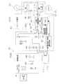
- FIG. 2 is a circuit diagram showing a connection relationship between the outdoor control unit 60 and the compressor 31.
- the circuit diagram shown in FIG. 2 shows a state when the outdoor unit 30 is in operation and no abnormality is detected.
- the outdoor control unit 60 includes an inverter board PCB1 and a control board PCB2.
- An inverter 61 and an inverter drive device 62 that drives the inverter 61 are mounted on the inverter board PCB1.
- An inverter 61 is connected to the compressor 31, and AC voltage is supplied to the compressor 31 from the inverter 61.
- the inverter 61 converts a DC voltage output from a filter circuit 69 described later into an AC voltage by PWM (Pulse Width Modulation) control.
- the inverter drive device 62 includes a rectifier circuit 68 and a filter circuit 69.
- the rectifier circuit 68 is connected to the commercial power source PS1.
- the rectifier circuit 68 rectifies the AC voltage supplied from the commercial power source PS1 into a DC voltage.
- the filter circuit 69 is connected to the rectifier circuit 68.
- the filter circuit 69 includes a reactor L1 and a capacitor C1. The harmonic current is suppressed by the inductance of the reactor L1, and the ripple component of the DC voltage output from the rectifier circuit 68 is smoothed by the capacitance of the capacitor C1. Filter noise.
- the inverter 61 is connected to the filter circuit 69.
- the inverter drive device 62 performs PWM control on the inverter 61.
- the inverter drive device 62 includes a PWM drive circuit 65.
- the PWM drive circuit 65 is a drive circuit for the inverter 61 that transmits a gate signal GS to the inverter 61.
- This gate signal GS is a drive signal for driving the inverter 61.
- the inverter driving device 62 is supplied with a voltage V1 (for example, DC15V) from an inverter driving power source PS2 for driving the PWM driving circuit 65. Further, the inverter drive device 62 includes a first mechanical relay RY1 for disconnecting the inverter drive power source PS2 from the PWM drive circuit 65.
- the common contact CP1 of the first mechanical relay RY1 is connected to the inverter driving power source PS2, and the PWM drive circuit 65 is connected to the break contact CP2 (shown as A contact in FIG. 10) of the first mechanical relay RY1.
- An abnormal signal transmission circuit 66 described later is connected to the make contact CP3 (shown as B contact in FIG. 10) of the first mechanical relay RY1.
- the inverter drive device 62 includes a CPU (central processing unit) 63, an abnormal signal transmission circuit 66, and an emergency stop information detection circuit 67.
- the CPU 63 is supplied with an inverter control voltage V2 (for example, DC15V) from the inverter control power supply PS3. ing.
- the CPU 63 transmits a PWM signal PWMS that gives information necessary for the PWM drive circuit 65 to generate the gate signal GS to the PWM drive circuit 65.
- the abnormality signal transmission circuit 66 transmits a high voltage abnormality detection signal HPSS to the CPU 63.
- the CPU 63 that has received the high voltage abnormality detection signal HPSS stops the PWM drive circuit 65.
- the emergency stop information detection circuit 67 detects information instructing an emergency stop given from the outside of the inverter drive device 62.
- the emergency stop information detection circuit 67 transmits an emergency stop signal ESS to the CPU 63 when detecting information instructing emergency stop.
- the CPU 63 that has received the emergency stop signal ESS stops the PWM drive circuit 65.
- the inverter control power source PS3 is supplied to the inverter board PCB1 independently of the inverter drive power source PS2, and the inverter control power source PS3 is supplied to the CPU 63 even if the inverter control power source PS3 is cut off by the first mechanical relay RY1. The state is kept.
- the inverter drive device 62 includes a first connection port X1A and a second connection port X2A connected in series with each other.
- the first connection port X1A and the second connection port X2A are break contacts.
- the first mechanical relay RY1 has a coil to which the voltage V1 is applied from the inverter driving power source PS2 via the first connection port X1A and the second connection port X2A.
- the common contact CP1 and the break contact CP2 are connected.
- the common contact CP1 and the make contact CP3 are connected.
- An emergency stop circuit 110 is connected to the second connection port X2A.
- the emergency stop circuit 110 is provided with, for example, a button switch 111 so that the button switch 111 can be pressed when the user determines that an emergency stop is necessary.
- the button switch 111 is pressed, the button switch 111 is opened and the second connection port X2A is also opened. Further, when the button switch 111 is pressed, the emergency stop circuit 110 sends information for instructing an emergency stop to the emergency stop information detection circuit 67.
- the control board PCB2 is supplied with a voltage V3 (for example, DC15V) from the control board power supply PS4.
- V3 for example, DC15V
- a third connection port X3A, a second mechanical relay RY2, and a fourth connection port X4A are mounted on the control board PCB2.
- the voltage V3 is applied to the coil of the second mechanical relay RY2 via the third connection port X3A.
- the third connection port X3A is connected to the high pressure abnormality detection unit 41.
- the high voltage abnormality detection unit 41 connected to the third connection port X3A detects a high voltage abnormality, the high voltage abnormality detection unit 41 is turned off, and the supply of the voltage V3 to the coil of the second mechanical relay RY2 is shut off.
- the break contact of the second mechanical relay RY2 is connected to the fourth connection port X4A, and the fourth connection port X4A is connected to the first connection port X1A.
- the connection between the second mechanical relay RY2, the fourth connection port X4A and the first connection port X1A is such that when the second mechanical relay RY2 is opened, the fourth connection port X4A is opened and the fourth connection port X4A is opened. Then, the connection is such that the first connection port X1A is also open. In other words, when the second mechanical relay RY2 is closed, the fourth connection port X4A and the first connection port X1A are also closed.
- the operation of the inverter drive device 62 will be described with reference to FIG. 3, FIG. 4, and FIG.
- the air conditioner 10 including the outdoor unit 30 is not supplied with power to the control board PCB2 and the inverter board PCB1 until the commercial power supply PS1 is turned off until the time t1, so that the operation is stopped and the inverter driving power supply PS2 is supplied.
- the voltage V1, the inverter control voltage V2 of the inverter control power supply PS3, and the voltage V3 of the control board power supply PS4 are all 0V. Therefore, until the time t1, the CPU 63, the PWM drive circuit 65, the abnormal signal transmission circuit 66, and the emergency stop information detection circuit 67 do not operate. Until time t1, the common contact CP1 and the make contact CP3 of the first mechanical relay RY1 are connected, and the second mechanical relay RY2 is open.
- the inverter 63 is supplied with the inverter control voltage.
- V2 is applied and a voltage V3 is applied to the second mechanical relay RY2.
- the voltage V3 may be applied to the second mechanical relay RY2.
- the first mechanical relay RY1 is delayed in response by a time required for switching the contact connection of the first mechanical relay RY1 until the first mechanical relay RY1 switches from the make contact CP3 to the break contact CP2. Occurs. Therefore, there is a slight delay from when the voltage V1 of the inverter driving power source PS2 is supplied to the inverter board PCB1 until the voltage V1 is applied to the PWM driving circuit 65 as shown in FIG.
- a device formed of a semiconductor such as the CPU 63 and the abnormal signal transmission circuit 66 generally has a faster rising speed than a device that requires mechanical operation such as the first mechanical relay RY1. If such a CPU 63 or abnormal signal transmission circuit 66 starts to operate quickly, a malfunction such as a malfunction may occur. For example, when the abnormality signal transmission circuit 66 starts operating in a state where the common contact CP1 and the make contact CP3 of the first mechanical relay RY1 are connected, the high voltage abnormality detection signal HPSS is transmitted from the abnormality signal transmission circuit 66. there is a possibility.
- the CPU 63 When the CPU 63 starts operating with the common contact CP1 and the make contact CP3 of the first mechanical relay RY1 connected, the voltage V1 is not yet applied to the PWM drive circuit 65 from the inverter drive power supply PS2. There is a possibility that the CPU 63 outputs the PWM signal PWMS to the stopped PWM drive circuit 65. If a part of the PWM signal PWMS is missing in this way, the driving of the inverter motor 80 of the compressor 31 may be hindered. Alternatively, when the rise of the voltage V3 of the control board power supply PS4 of the control board PCB2 is slower than the inverter control voltage V2, the second mechanical relay RY2 of the control board PCB2 is closed even when the CPU 63 starts operating. First, the first connection port S1A of the inverter board PCB1 becomes open, and the CPU 63 may erroneously detect a high voltage abnormality even though it is not a high voltage abnormality.
- the CPU 63 has a mask processing function for stopping the control for a predetermined period after the inverter control voltage V2 is supplied from the inverter control power source PS3. As shown in FIG. 15, the standby state is maintained without performing control only for a certain period (t2-t1) from time t1 to time t2.
- the voltage V1 of the inverter driving power supply PS2 is set to the first machine.
- the case where the compressor 31 is stopped by being interrupted by the relay RY1 the case where the compressor 31 is stopped by stopping the transmission of the PWM signal PWMS of the CPU 63.
- the transmission of the gate signal GS of the PWM drive circuit 65 is stopped as shown in FIG. 12, and the operation of the compressor 31 is stopped as shown in FIG.
- the transmission of the PWM signal PWMS from the CPU 63 to the PWM drive circuit 65 is stopped.
- the transmission of the PWM signal PWMS is stopped by the compressor 31. Does not affect the suspension of operation.
- the high voltage abnormality is resolved slightly after time t6, and the high voltage abnormality signal HPS from the high voltage abnormality detection unit 41 is canceled.
- the second mechanical relay RY2 is closed slightly after the release of the high voltage abnormality signal HPS.
- the fourth connection port X4A and the first connection port X1A are closed, and the first mechanical relay RY1 is switched from the B contact to the A contact.
- the voltage V1 is applied to the PWM drive circuit 65, and the gate signal GS from the PWM drive circuit 65 can be output.
- the CPU 63 performs mask processing from the abnormality signal transmission circuit 66. From the time t8, transmission of the PWM signal PWMS to the PWM drive circuit 65 of the CPU 63 is started with a slight delay after the output of the abnormal signal from is stopped. As a result, transmission of the gate signal GS of the PWM drive circuit 65 is started, and the application of the AC voltage by the inverter 61 and the operation of the compressor 31 are resumed.
- the transmission of the PWM signal PWMS from the CPU 63 is stopped as shown in FIG. 7, and the transmission of the gate signal GS of the PWM drive circuit 65 is stopped as shown in FIG.
- the operation of the compressor 31 is stopped.
- the voltage V1 of the inverter drive power supply PS2 to the PWM drive circuit 65 is cut off by the first mechanical relay RY1, but at this time, transmission of the PWM signal PWMS to the PWM drive circuit 65 is already stopped. Therefore, the interruption of the voltage V1 by the first mechanical relay RY1 does not affect the stop of the operation of the compressor 31.
- the high voltage abnormality is resolved slightly after time t13, and the high voltage abnormality signal HPS from the high voltage abnormality detection unit 41 is canceled.
- the second mechanical relay RY2 is closed slightly after the release of the high voltage abnormality signal HPS.
- the fourth connection port X4A and the first connection port X1A are closed, and the first mechanical relay RY1 is switched from the B contact to the A contact.
- the voltage V1 is applied to the PWM drive circuit 65, and the gate signal GS from the PWM drive circuit 65 can be output.
- the CPU 63 performs mask processing from the abnormality signal transmission circuit 66. From the time t15, transmission of the PWM signal PWMS to the PWM drive circuit 65 of the CPU 63 is started with a slight delay after the output of the abnormal signal from is stopped. As a result, transmission of the gate signal GS of the PWM drive circuit 65 is started, and the application of the AC voltage by the inverter 61 and the operation of the compressor 31 are resumed.
- the commercial power supply PS1 is turned off at time t16, power is not supplied to the control board PCB2 and the inverter board PCB1, the voltage V1 of the inverter driving power supply PS2, and the inverter control voltage V2 of the inverter control power supply PS3 (see FIG. 6).
- the voltages V3 of the control board power supply PS4 are all 0V.
- the first mechanical relay RY1 is switched from the break contact CP2 (A contact) to the make contact PC3 (B contact), and the second mechanical relay RY2 is opened.
- the first mechanical relay RY1 drives the inverter of the PWM drive circuit 65.
- Power supply PS2 is shut off.
- the inverter motor 80 and the compressor 31 incorporating the inverter motor 80 are actuators. In this way, the inverter driving power source PS2 is cut off and the contact is mechanically opened and closed inside the first mechanical relay RY1, so that the contact is mechanically disconnected.
- the contact is mechanically opened inside the first mechanical relay RY1, the drive signal for the inverter 61 is reliably changed, and the driven inverter 61 is reliably stopped.
- the drive of the inverter 61 can be stopped reliably, and the reliability of the drive stop of the compressor 31 is improved. Further, for example, even if a malfunction such as the first mechanical relay RY1 does not operate due to disconnection or the like, the first mechanical relay RY1 maintains the state where the common contact CP1 is connected to the make contact CP3, so that safety is ensured. Kept.
- the inverter motor 80 of the compressor 31 has been described as an example.
- the present invention can also be applied to the inverter motor 70 of the indoor fan 22 and the inverter motor 90 of the outdoor fan 37. Even in this case, the same effect can be obtained.
- the first mechanical relay RY1 is connected to the common contact CP1 connected to the inverter drive power source PS2 of the PWM drive circuit 65, the break contact CP2 connected to the PWM drive circuit 65, and the abnormal signal transmission circuit 66. It is configured to include a make contact CP3. Since it is configured in this manner, an abnormality is notified by disconnecting the inverter driving power source PS2 from the PWM drive circuit 65 and applying the voltage V1 to the abnormality signal transmission circuit 66 in one operation of the first mechanical relay RY1. Therefore, it is possible to quickly and surely detect an abnormality, and to prevent the CPU 63 (an example of a microcomputer) from erroneously detecting an abnormality detection other than the abnormality detection related to the first mechanical relay RY1. it can. With the configuration as described above, it is possible to provide the inverter driving device 62 that can quickly and surely stop and detect abnormality of the inverter driving power source PS2 of the PWM driving circuit 65 at low cost.
- a high voltage abnormality detection unit 41 capable of outputting a request to stop driving the inverter motor 80 of the compressor 31 is connected to the first connection port X1A via the control board PCB2.
- the first connection port X1A is closed by the high voltage abnormality detection unit 41 and an abnormality is detected, the first connection port X1A is opened by the high voltage abnormality detection unit 41 and opened, and the inverter of the PWM drive circuit 65
- the first mechanical relay RY1 can operate so that the driving power supply PS2 is cut off. In this way, a device such as the high-pressure abnormality detection unit 41 that detects an abnormality of the air conditioner 10 and requests the actuator to stop driving can be easily connected using the first connection port X1A.
- a first mechanical relay RY1 is attached to the inverter board PCB1.
- This inverter substrate PCB1 is the first substrate.
- a second mechanical relay RY2 is attached to a control board PCB2 that is separate from the inverter board PCB1.
- This control board PCB2 is the second board.
- the control board PCB2 can be provided in a place where the inverter board PCB1 is not provided.
- the control board PCB2 can be arranged on the front side of the outdoor unit 30 and the inverter board PCB1 can be arranged on the back side of the outdoor unit 30 so that maintenance and setting of the air conditioner 10 can be easily performed.
- the control board PCB2 and the control board PCB2 are separated by a partition plate (not shown) so that the operator does not touch the inverter board PCB1 during maintenance and setting operations.
- the inverter board PCB1 can be partitioned. In other words, when the first board is provided in a closed place, the second board is provided in a place where the second board can be opened, and the second mechanical relay RY2 and the high voltage abnormality detection unit 41 can be easily connected. can do.
- the high-pressure abnormality detection unit 41 which is a device for which a request to stop driving of the actuator is output in this way, is provided in a place where it is easy to connect, for example, when the compressor 31 is disposed on the front side of the machine room, the control board When the PCB 2 is arranged on the front side, the connection between the second mechanical relay RY2 and the high voltage abnormality detection unit 41 can be easily performed.
- the connection between the high-pressure abnormality detection unit 41 that is a device that requests the stop of the driving of the actuator and the first mechanical relay RY1 is the first connection port X1A and the second connection. This is facilitated through the mechanical relay RY2.
- the second connection port X2A is connected in series to the first connection port X1A and the first mechanical relay RY1.
- the first mechanical relay RY1 can reliably change the gate signal GS for the inverter 61, and the driven inverter can be reliably stopped. As a result, the certainty of stopping the driving of the inverter motor 80 of the compressor 31 by the emergency stop circuit 110 is improved.
- the gate signal GS is a drive signal output from the drive circuit to the inverter.
- the CPU 63 may stop the inverter 61 earlier than the case where the inverter 61 is stopped only by the first mechanical relay RY1. In such a case, the time until the inverter motor 80 of the compressor 31 stops when it is abnormal can be shortened. As a result, the protection of the compressor 31 and the inverter motor 80 of the compressor 31 can be improved.
- the inverter drive power source PS2 and the inverter control power source PS3 can be shared.
- JP 2007-107781 A Japanese Patent No. 4151188
Landscapes
- Engineering & Computer Science (AREA)
- Mechanical Engineering (AREA)
- General Engineering & Computer Science (AREA)
- Chemical & Material Sciences (AREA)
- Combustion & Propulsion (AREA)
- Power Engineering (AREA)
- Physics & Mathematics (AREA)
- Thermal Sciences (AREA)
- Air Conditioning Control Device (AREA)
- Control Of Electric Motors In General (AREA)
- Control Of Ac Motors In General (AREA)
- Inverter Devices (AREA)
Priority Applications (4)
| Application Number | Priority Date | Filing Date | Title |
|---|---|---|---|
| BR112017020784-2A BR112017020784B1 (pt) | 2015-04-16 | 2016-03-28 | Acionador de inversor de condicionador de ar |
| EP16779902.2A EP3285387A4 (de) | 2015-04-16 | 2016-03-28 | Antriebsvorrichtung für einen wechselrichter einer klimaanlage |
| CN201680021692.5A CN107580750B (zh) | 2015-04-16 | 2016-03-28 | 空调机的逆变器驱动装置 |
| US15/565,632 US10619878B2 (en) | 2015-04-16 | 2016-03-28 | Inverter driver of air conditioner |
Applications Claiming Priority (2)
| Application Number | Priority Date | Filing Date | Title |
|---|---|---|---|
| JP2015-083923 | 2015-04-16 | ||
| JP2015083923A JP6464903B2 (ja) | 2015-04-16 | 2015-04-16 | 空気調和機のインバータ駆動装置 |
Publications (1)
| Publication Number | Publication Date |
|---|---|
| WO2016167111A1 true WO2016167111A1 (ja) | 2016-10-20 |
Family
ID=57126749
Family Applications (1)
| Application Number | Title | Priority Date | Filing Date |
|---|---|---|---|
| PCT/JP2016/059883 Ceased WO2016167111A1 (ja) | 2015-04-16 | 2016-03-28 | 空気調和機のインバータ駆動装置 |
Country Status (6)
| Country | Link |
|---|---|
| US (1) | US10619878B2 (de) |
| EP (1) | EP3285387A4 (de) |
| JP (1) | JP6464903B2 (de) |
| CN (1) | CN107580750B (de) |
| BR (1) | BR112017020784B1 (de) |
| WO (1) | WO2016167111A1 (de) |
Cited By (4)
| Publication number | Priority date | Publication date | Assignee | Title |
|---|---|---|---|---|
| CN108625109A (zh) * | 2017-03-24 | 2018-10-09 | 东芝生活电器株式会社 | 洗衣机 |
| CN108679799A (zh) * | 2018-03-07 | 2018-10-19 | 南京天加环境科技有限公司 | 一种螺杆压缩机组的能量调节方法 |
| CN111295828A (zh) * | 2017-11-06 | 2020-06-16 | 大金工业株式会社 | 电力变换装置和空调装置 |
| WO2020188764A1 (ja) * | 2019-03-19 | 2020-09-24 | 三菱電機株式会社 | モータ駆動制御装置および空気調和機の室外機 |
Families Citing this family (7)
| Publication number | Priority date | Publication date | Assignee | Title |
|---|---|---|---|---|
| CN106871354B (zh) * | 2017-02-22 | 2019-08-02 | 海信(广东)空调有限公司 | 一种变频空调的功率控制方法及系统 |
| JP6851331B2 (ja) * | 2018-01-11 | 2021-03-31 | ダイキン工業株式会社 | 電力変換装置及び空気調和装置 |
| CN111954785B (zh) * | 2018-04-18 | 2021-11-02 | 三菱电机株式会社 | 控制基板以及空调机的室内机 |
| CN111005862B (zh) * | 2019-12-16 | 2022-02-15 | 广东美的暖通设备有限公司 | 压力保护电路、控制方法和计算机可读存储介质 |
| BE1028230B1 (de) * | 2020-04-22 | 2021-12-03 | Phoenix Contact Gmbh & Co | Energieversorgungsvorrichtung mit sicherheitsgerichteter Abschaltung sowie Verfahren zum Abschalten einer Energieversorgungsvorrichtung |
| US20240128917A1 (en) * | 2021-05-11 | 2024-04-18 | Mitsubishi Electric Corporation | Motor drive device and outdoor unit of air-conditioning apparatus, which includes the same |
| CN113325766B (zh) * | 2021-05-26 | 2023-05-30 | 珠海格力电器股份有限公司 | 一种驱动控制芯片、暖通设备 |
Citations (5)
| Publication number | Priority date | Publication date | Assignee | Title |
|---|---|---|---|---|
| JPS58163272A (ja) * | 1982-03-19 | 1983-09-28 | Sanyo Electric Co Ltd | インバ−タ装置 |
| JPH08149833A (ja) * | 1994-11-18 | 1996-06-07 | Sanyo Electric Co Ltd | 太陽電池発電装置の制御用電源回路及び保護回路 |
| JP2007107781A (ja) * | 2005-10-12 | 2007-04-26 | Sanyo Electric Co Ltd | 空気調和装置 |
| JP2010181110A (ja) * | 2009-02-06 | 2010-08-19 | Mitsubishi Electric Corp | 冷凍サイクル装置 |
| JP2012070595A (ja) * | 2010-09-27 | 2012-04-05 | Daikin Ind Ltd | 冷凍装置のインバータ基板 |
Family Cites Families (16)
| Publication number | Priority date | Publication date | Assignee | Title |
|---|---|---|---|---|
| JP2865382B2 (ja) * | 1990-05-29 | 1999-03-08 | 三洋電機株式会社 | 空気調和機の制御装置 |
| JP4151188B2 (ja) | 2000-02-29 | 2008-09-17 | 松下電器産業株式会社 | マルチタイプ空気調和機の制御装置 |
| JP4075951B2 (ja) * | 2006-03-08 | 2008-04-16 | ダイキン工業株式会社 | 負荷駆動装置及び空気調和機の室外機並びに負荷の駆動方法 |
| JP4155307B2 (ja) * | 2006-03-29 | 2008-09-24 | ダイキン工業株式会社 | 空気調和装置の制御装置 |
| JP4650477B2 (ja) * | 2007-10-30 | 2011-03-16 | ダイキン工業株式会社 | 漏電検出方法 |
| KR101270336B1 (ko) * | 2009-04-17 | 2013-05-31 | 다이킨 고교 가부시키가이샤 | 전원 회로, 및 전원 회로의 제어 프로그램을 기억한 컴퓨터 판독 가능한 기억 매체 |
| JP5454596B2 (ja) * | 2012-02-08 | 2014-03-26 | ダイキン工業株式会社 | 電源制御装置 |
| CN104412500B (zh) * | 2012-07-09 | 2016-11-16 | 松下知识产权经营株式会社 | 密闭式电动压缩机的控制装置和密闭式电动压缩装置、以及具备这些装置的家电产品 |
| GB2538885B (en) * | 2014-03-24 | 2020-02-19 | Mitsubishi Electric Corp | Air conditioning system and transmission relaying apparatus thereof |
| CN106537053A (zh) * | 2014-06-20 | 2017-03-22 | 江森自控日立空调技术(香港)有限公司 | 显示装置、方法以及程序 |
| JP6281430B2 (ja) * | 2014-07-15 | 2018-02-21 | トヨタ自動車株式会社 | 電動機制御装置 |
| JP6359423B2 (ja) * | 2014-10-24 | 2018-07-18 | 三菱重工業株式会社 | 空調システムの制御装置、空調システム、及び空調システムの制御装置の異常判定方法 |
| JP2016084969A (ja) * | 2014-10-24 | 2016-05-19 | 三菱重工業株式会社 | 空調システムの制御装置、空調システム、及び空調システムの異常判定方法 |
| US9689582B2 (en) * | 2015-04-10 | 2017-06-27 | Lennox Industries Inc. | Overvoltage recovery circuit and a controller and HVAC system including the same |
| US10158312B2 (en) * | 2016-01-20 | 2018-12-18 | Toyota Jidosha Kabushiki Kaisha | Motor control apparatus |
| JP6285475B2 (ja) * | 2016-01-29 | 2018-02-28 | ファナック株式会社 | 放電機能を有するモータ駆動装置 |
-
2015
- 2015-04-16 JP JP2015083923A patent/JP6464903B2/ja active Active
-
2016
- 2016-03-28 CN CN201680021692.5A patent/CN107580750B/zh active Active
- 2016-03-28 BR BR112017020784-2A patent/BR112017020784B1/pt active IP Right Grant
- 2016-03-28 EP EP16779902.2A patent/EP3285387A4/de not_active Withdrawn
- 2016-03-28 WO PCT/JP2016/059883 patent/WO2016167111A1/ja not_active Ceased
- 2016-03-28 US US15/565,632 patent/US10619878B2/en active Active
Patent Citations (5)
| Publication number | Priority date | Publication date | Assignee | Title |
|---|---|---|---|---|
| JPS58163272A (ja) * | 1982-03-19 | 1983-09-28 | Sanyo Electric Co Ltd | インバ−タ装置 |
| JPH08149833A (ja) * | 1994-11-18 | 1996-06-07 | Sanyo Electric Co Ltd | 太陽電池発電装置の制御用電源回路及び保護回路 |
| JP2007107781A (ja) * | 2005-10-12 | 2007-04-26 | Sanyo Electric Co Ltd | 空気調和装置 |
| JP2010181110A (ja) * | 2009-02-06 | 2010-08-19 | Mitsubishi Electric Corp | 冷凍サイクル装置 |
| JP2012070595A (ja) * | 2010-09-27 | 2012-04-05 | Daikin Ind Ltd | 冷凍装置のインバータ基板 |
Non-Patent Citations (1)
| Title |
|---|
| See also references of EP3285387A4 * |
Cited By (6)
| Publication number | Priority date | Publication date | Assignee | Title |
|---|---|---|---|---|
| CN108625109A (zh) * | 2017-03-24 | 2018-10-09 | 东芝生活电器株式会社 | 洗衣机 |
| CN108625109B (zh) * | 2017-03-24 | 2020-11-06 | 东芝生活电器株式会社 | 洗衣机 |
| CN111295828A (zh) * | 2017-11-06 | 2020-06-16 | 大金工业株式会社 | 电力变换装置和空调装置 |
| CN111295828B (zh) * | 2017-11-06 | 2023-09-12 | 大金工业株式会社 | 电力变换装置和空调装置 |
| CN108679799A (zh) * | 2018-03-07 | 2018-10-19 | 南京天加环境科技有限公司 | 一种螺杆压缩机组的能量调节方法 |
| WO2020188764A1 (ja) * | 2019-03-19 | 2020-09-24 | 三菱電機株式会社 | モータ駆動制御装置および空気調和機の室外機 |
Also Published As
| Publication number | Publication date |
|---|---|
| CN107580750A (zh) | 2018-01-12 |
| US20180073765A1 (en) | 2018-03-15 |
| BR112017020784A2 (pt) | 2018-06-26 |
| EP3285387A1 (de) | 2018-02-21 |
| CN107580750B (zh) | 2020-05-08 |
| US10619878B2 (en) | 2020-04-14 |
| JP2016208575A (ja) | 2016-12-08 |
| BR112017020784B1 (pt) | 2023-05-09 |
| EP3285387A4 (de) | 2019-01-16 |
| JP6464903B2 (ja) | 2019-02-06 |
Similar Documents
| Publication | Publication Date | Title |
|---|---|---|
| JP6464903B2 (ja) | 空気調和機のインバータ駆動装置 | |
| JP5984732B2 (ja) | 空気調和機 | |
| JP5241585B2 (ja) | 空気調和機 | |
| AU2010238133B2 (en) | Power circuit, and computer-readable recording medium storing a control program for power circuits | |
| JP5382105B2 (ja) | 空気調和装置 | |
| JP5289086B2 (ja) | 冷凍サイクル装置 | |
| JP5582989B2 (ja) | 空気調和装置 | |
| JP4075951B2 (ja) | 負荷駆動装置及び空気調和機の室外機並びに負荷の駆動方法 | |
| WO2019021397A1 (ja) | 空気調和機 | |
| JP5502062B2 (ja) | 空気調和機 | |
| JP5655775B2 (ja) | 空気調和装置 | |
| JP5804009B2 (ja) | 空気調和装置 | |
| JP5686754B2 (ja) | 空気調和機 | |
| KR101257094B1 (ko) | 오결선 감지 장치 및 이를 구비한 공기 조화기 | |
| JP2013085319A (ja) | 空気調和機 | |
| CN203757951U (zh) | 空调机控制装置 | |
| JP2013148303A (ja) | 空気調和機 | |
| JP2013137135A (ja) | 空気調和装置 | |
| JP7047499B2 (ja) | 電力変換装置 | |
| JP2000002188A (ja) | 空気調和機の制御装置 | |
| JP5246324B2 (ja) | 空気調和装置 | |
| JP2010252567A (ja) | 電源回路 | |
| JP2016169884A (ja) | 空気調和機のモータ駆動装置 | |
| TW201909540A (zh) | 家電機器 | |
| JP2012047367A (ja) | 空気調和機 |
Legal Events
| Date | Code | Title | Description |
|---|---|---|---|
| 121 | Ep: the epo has been informed by wipo that ep was designated in this application |
Ref document number: 16779902 Country of ref document: EP Kind code of ref document: A1 |
|
| REG | Reference to national code |
Ref country code: BR Ref legal event code: B01A Ref document number: 112017020784 Country of ref document: BR |
|
| WWE | Wipo information: entry into national phase |
Ref document number: 15565632 Country of ref document: US |
|
| NENP | Non-entry into the national phase |
Ref country code: DE |
|
| ENP | Entry into the national phase |
Ref document number: 112017020784 Country of ref document: BR Kind code of ref document: A2 Effective date: 20170928 |