WO2016167239A1 - 立体物造形方法及び3次元プリンタ - Google Patents
立体物造形方法及び3次元プリンタ Download PDFInfo
- Publication number
- WO2016167239A1 WO2016167239A1 PCT/JP2016/061784 JP2016061784W WO2016167239A1 WO 2016167239 A1 WO2016167239 A1 WO 2016167239A1 JP 2016061784 W JP2016061784 W JP 2016061784W WO 2016167239 A1 WO2016167239 A1 WO 2016167239A1
- Authority
- WO
- WIPO (PCT)
- Prior art keywords
- dimensional object
- ink
- unit
- printing
- layer
- Prior art date
- Legal status (The legal status is an assumption and is not a legal conclusion. Google has not performed a legal analysis and makes no representation as to the accuracy of the status listed.)
- Ceased
Links
Images







Classifications
-
- H—ELECTRICITY
- H04—ELECTRIC COMMUNICATION TECHNIQUE
- H04N—PICTORIAL COMMUNICATION, e.g. TELEVISION
- H04N1/00—Scanning, transmission or reproduction of documents or the like, e.g. facsimile transmission; Details thereof
- H04N1/40—Picture signal circuits
-
- B—PERFORMING OPERATIONS; TRANSPORTING
- B29—WORKING OF PLASTICS; WORKING OF SUBSTANCES IN A PLASTIC STATE IN GENERAL
- B29C—SHAPING OR JOINING OF PLASTICS; SHAPING OF MATERIAL IN A PLASTIC STATE, NOT OTHERWISE PROVIDED FOR; AFTER-TREATMENT OF THE SHAPED PRODUCTS, e.g. REPAIRING
- B29C64/00—Additive manufacturing, i.e. manufacturing of three-dimensional [3D] objects by additive deposition, additive agglomeration or additive layering, e.g. by 3D printing, stereolithography or selective laser sintering
- B29C64/10—Processes of additive manufacturing
- B29C64/106—Processes of additive manufacturing using only liquids or viscous materials, e.g. depositing a continuous bead of viscous material
- B29C64/112—Processes of additive manufacturing using only liquids or viscous materials, e.g. depositing a continuous bead of viscous material using individual droplets, e.g. from jetting heads
-
- B—PERFORMING OPERATIONS; TRANSPORTING
- B29—WORKING OF PLASTICS; WORKING OF SUBSTANCES IN A PLASTIC STATE IN GENERAL
- B29C—SHAPING OR JOINING OF PLASTICS; SHAPING OF MATERIAL IN A PLASTIC STATE, NOT OTHERWISE PROVIDED FOR; AFTER-TREATMENT OF THE SHAPED PRODUCTS, e.g. REPAIRING
- B29C31/00—Handling, e.g. feeding of the material to be shaped, storage of plastics material before moulding; Automation, i.e. automated handling lines in plastics processing plants, e.g. using manipulators or robots
- B29C31/04—Feeding of the material to be moulded, e.g. into a mould cavity
- B29C31/042—Feeding of the material to be moulded, e.g. into a mould cavity using dispensing heads, e.g. extruders, placed over or apart from the moulds
- B29C31/044—Feeding of the material to be moulded, e.g. into a mould cavity using dispensing heads, e.g. extruders, placed over or apart from the moulds with moving heads for distributing liquid or viscous material into the moulds
- B29C31/045—Feeding of the material to be moulded, e.g. into a mould cavity using dispensing heads, e.g. extruders, placed over or apart from the moulds with moving heads for distributing liquid or viscous material into the moulds moving along predetermined circuits or distributing the material according to predetermined patterns
-
- B—PERFORMING OPERATIONS; TRANSPORTING
- B29—WORKING OF PLASTICS; WORKING OF SUBSTANCES IN A PLASTIC STATE IN GENERAL
- B29C—SHAPING OR JOINING OF PLASTICS; SHAPING OF MATERIAL IN A PLASTIC STATE, NOT OTHERWISE PROVIDED FOR; AFTER-TREATMENT OF THE SHAPED PRODUCTS, e.g. REPAIRING
- B29C67/00—Shaping techniques not covered by groups B29C39/00 - B29C65/00, B29C70/00 or B29C73/00
-
- B—PERFORMING OPERATIONS; TRANSPORTING
- B33—ADDITIVE MANUFACTURING TECHNOLOGY
- B33Y—ADDITIVE MANUFACTURING, i.e. MANUFACTURING OF THREE-DIMENSIONAL [3D] OBJECTS BY ADDITIVE DEPOSITION, ADDITIVE AGGLOMERATION OR ADDITIVE LAYERING, e.g. BY 3D PRINTING, STEREOLITHOGRAPHY OR SELECTIVE LASER SINTERING
- B33Y10/00—Processes of additive manufacturing
-
- B—PERFORMING OPERATIONS; TRANSPORTING
- B33—ADDITIVE MANUFACTURING TECHNOLOGY
- B33Y—ADDITIVE MANUFACTURING, i.e. MANUFACTURING OF THREE-DIMENSIONAL [3D] OBJECTS BY ADDITIVE DEPOSITION, ADDITIVE AGGLOMERATION OR ADDITIVE LAYERING, e.g. BY 3D PRINTING, STEREOLITHOGRAPHY OR SELECTIVE LASER SINTERING
- B33Y30/00—Apparatus for additive manufacturing; Details thereof or accessories therefor
-
- B—PERFORMING OPERATIONS; TRANSPORTING
- B33—ADDITIVE MANUFACTURING TECHNOLOGY
- B33Y—ADDITIVE MANUFACTURING, i.e. MANUFACTURING OF THREE-DIMENSIONAL [3D] OBJECTS BY ADDITIVE DEPOSITION, ADDITIVE AGGLOMERATION OR ADDITIVE LAYERING, e.g. BY 3D PRINTING, STEREOLITHOGRAPHY OR SELECTIVE LASER SINTERING
- B33Y50/00—Data acquisition or data processing for additive manufacturing
- B33Y50/02—Data acquisition or data processing for additive manufacturing for controlling or regulating additive manufacturing processes
-
- B—PERFORMING OPERATIONS; TRANSPORTING
- B29—WORKING OF PLASTICS; WORKING OF SUBSTANCES IN A PLASTIC STATE IN GENERAL
- B29C—SHAPING OR JOINING OF PLASTICS; SHAPING OF MATERIAL IN A PLASTIC STATE, NOT OTHERWISE PROVIDED FOR; AFTER-TREATMENT OF THE SHAPED PRODUCTS, e.g. REPAIRING
- B29C64/00—Additive manufacturing, i.e. manufacturing of three-dimensional [3D] objects by additive deposition, additive agglomeration or additive layering, e.g. by 3D printing, stereolithography or selective laser sintering
- B29C64/30—Auxiliary operations or equipment
- B29C64/386—Data acquisition or data processing for additive manufacturing
- B29C64/393—Data acquisition or data processing for additive manufacturing for controlling or regulating additive manufacturing processes
Definitions
- the present invention relates to a three-dimensional object forming method and a three-dimensional printer.
- a three-dimensional object modeling method and a three-dimensional printer described in Patent Document 1 below include a plurality of three-dimensional data including shape data for specifying the shape of a three-dimensional object and surface image data indicating a surface image. Divide into layers. The three-dimensional object modeling method and the three-dimensional printer eject ink as a modeling material from the ejection unit while moving the ejection unit along the printing path in the main scanning direction based on the cross-sectional slice information of each layer.
- the ink as a modeling material is ejected from the ejection part while moving the ejection part along the printing path in the main scanning direction.
- the three-dimensional object forming method and the three-dimensional printer form a three-dimensional object by repeating the step of ejecting ink while moving the discharge unit in the scanning direction and the step of moving the discharge unit in the sub-scanning direction. .
- the three-dimensional object modeled by the above-described three-dimensional printer of Patent Document 1 also stacks the boundaries between the print paths in order to form the three-dimensional object by stacking the layers, the three-dimensional object is subjected to main scanning. Streaks (grooves) parallel to the direction (first direction) may occur.
- the present invention has been made in view of the above, and an object of the present invention is to provide a three-dimensional object modeling method and a three-dimensional printer capable of suppressing the generation of streaks parallel to the first direction in a three-dimensional object. .
- the three-dimensional object modeling method divides three-dimensional data indicating the shape of the three-dimensional object and the image of the surface into a plurality of layers and cross-sectional slice information of each layer.
- the printing passes are formed in a plurality of rows in a second direction intersecting the first direction to form the layers, and the printing pass is performed between adjacent layers in the stacking direction of the layers.
- the printing pass is formed so that at least a part of the printing pass is shifted in the second direction between the stacked layers, and each layer is formed. For this reason, when laminating each layer, it can suppress that the boundary between printing passes is formed continuously in the laminating direction, and suppresses the generation of streaks parallel to the first direction in the three-dimensional object after modeling. be able to.
- the discharge unit that discharges the ink onto the landing surface includes a plurality of the inks from a plurality of nozzles arranged in the second direction at each position of the layer. It is assumed that each layer is formed by discharging twice and driven by nozzle discharge control in which the printing pass is set so that a boundary between the printing passes extends obliquely with respect to the first direction. it can.
- the print path is set so that the boundary between the print paths extends obliquely with respect to the first direction, so the boundary between the print paths becomes oblique with respect to the first direction. Even if streaks along the boundary between printing passes occur, it can be made inconspicuous.
- it is desirable that the direction in which the boundary of the printing path extends is different between the layers that are stacked on each other. In this case, in addition to the fact that it is possible to suppress the generation of streaks parallel to the first direction in the three-dimensional object after modeling, the upper surface of the three-dimensional object after modeling can be formed flat.
- an ejection unit that ejects the ink onto the landing surface receives the ink from a plurality of nozzles arranged in the second direction at each position of the layer.
- the ejection duty from the nozzles in the first direction of the ejection unit is changed so that each layer is formed by ejecting a plurality of times and the width of the printing path in the second direction changes in the first direction. It can be driven by nozzle discharge control.
- the boundary between the printing passes becomes oblique with respect to the first direction, Even if a line along the boundary is generated, it can be made inconspicuous.
- the boundary is not continuous and it is difficult to form continuous stripes.
- the method further includes a process determination step for determining whether or not the nozzle discharge control is performed for each portion of the cross-sectional slice information, and in the unit layer forming step, the discharge unit includes the process In the determination step, when the layer is formed based on the section slice information determined to be subjected to the nozzle discharge control, the layer may be driven by the nozzle discharge control.
- the present invention further includes a process determination step for determining, for each portion of the slice slice information, whether or not the nozzle discharge control is performed based on the slice slice information. For this reason, according to the present invention, the nozzle discharge control can be performed or not performed according to the shape of each layer, the color density of the surface image, and the like. Therefore, a more accurate three-dimensional object can be modeled.
- the discharge unit in the unit layer forming step, is configured to apply the layer based on the cross-sectional slice information portion that is determined not to perform the nozzle discharge control in the processing determination step.
- the printing path may be driven so as to form a printing path so that a boundary between the printing paths is parallel to the first direction.
- the print pass when it is determined that the nozzle discharge control is not performed, the print pass is set so that the print pass is parallel to the first direction. Therefore, the discharge is performed when ink is discharged along each print pass. Ink can be simultaneously ejected from as many nozzles as possible among the plurality of nozzles in the section. Therefore, since the ink landing accuracy is improved by discharging ink from many nozzles, it is possible to accurately model the details of the three-dimensional object.
- the above three-dimensional object modeling method it is possible to have a plurality of nozzle rows configured by a plurality of nozzles arranged in the second direction, and the nozzle discharge control is performed in units of the nozzle rows.
- nozzle discharge control since nozzle discharge control is performed in units of nozzle rows, it is possible to set whether or not to perform nozzle discharge control for each type of ink discharged from the nozzle rows. For this reason, it is possible to set whether or not to perform nozzle discharge control for each model part, color part, and clear part of each layer of the three-dimensional object. Therefore, nozzle discharge control can be appropriately performed in order to model a three-dimensional object with higher accuracy.
- the three-dimensional data includes surface image data indicating a color of the surface of the three-dimensional object, and in the processing determination step, the surface image data as the portion of the cross-sectional slice information. Based on the above, it can be determined whether or not the nozzle discharge control is performed.
- the presence / absence of the nozzle discharge control is determined based on the surface image data of the slice slice information. For this reason, for example, nozzle discharge control is performed when the surface color of the solid object is dark, and nozzle discharge control is not performed when the surface color is thin. It is possible to appropriately determine the presence or absence of implementation. For this reason, it is possible to improve the ink landing accuracy in the light-colored portion of the surface of the three-dimensional object, and it is possible to suppress the generation of streaks parallel to the main scanning direction in the dark portion.
- a cross section that determines whether or not the nozzle discharge control is performed when it is determined whether or not the nozzle discharge control is performed for each section slice information.
- a region that overlaps the cross-sectional slice information that is modeled after the slice slice information that compares the slice information with the shape of the cross-sectional slice information that is modeled after the slice and determines whether or not the nozzle discharge control is performed It can be determined that the nozzle discharge control is performed.
- nozzle ejection control is performed when a region that overlaps the cross-sectional slice information that is formed immediately after the cross-sectional slice information is formed. For this reason, for example, in the part where the layers of the three-dimensional object are laminated, the boundary between the printing passes can be suppressed, and the modeling accuracy of the upper layer can be improved.
- the discharge unit discharges ink from all of the plurality of nozzles arranged in the second direction when forming at least a part of the printing pass
- the printing pass may be formed so that the entire boundary between the printing passes is shifted in the second direction between adjacent layers in the stacking direction of the layers.
- the printing pass is formed so that the boundary between the printing passes is shifted in the second direction between the layers to be laminated with each other, the lamination of the printing pass can be suppressed when each layer is laminated. It is possible to suppress the generation of streaks parallel to the first direction in the subsequent three-dimensional object.
- a three-dimensional printer is a three-dimensional printer that models the three-dimensional object based on three-dimensional data indicating the shape of the three-dimensional object and an image of the surface, and is covered with ink for modeling the three-dimensional object.
- a discharge unit that discharges to a landing surface; and a control device that controls the discharge unit and the phase difference moving unit. The control device divides the three-dimensional data into a plurality of layers and slices each of the layers.
- the unit layer forming step performs a printing step of forming a single row of printing passes extending in the first direction by the discharge unit, and the printing pass in a second direction intersecting the first direction.
- the A plurality of rows are formed to form each of the layers, and the printing pass is formed so that at least a part of the boundary between the printing passes is shifted in the second direction between adjacent layers in the stacking direction of the layers. It is characterized by that.
- each layer is formed by forming a printing pass so that at least a part of the printing pass is shifted in the second direction between layers stacked on each other. For this reason, when each layer is laminated
- the three-dimensional object modeling method and the three-dimensional printer according to the present invention have an effect that it is possible to suppress the generation of streaks parallel to the first direction in the three-dimensional object.
- FIG. 1 is a schematic configuration diagram illustrating a schematic configuration of an inkjet printer according to an embodiment.
- FIG. 2 is an example of a flowchart of the three-dimensional object modeling method according to the embodiment.
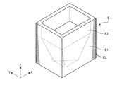
- FIG. 3 is a perspective view showing an example of a three-dimensional object formed by the ink jet printer shown in FIG.
- FIG. 4 is a perspective view showing an example of a support body used when modeling the three-dimensional object shown in FIG. 3.
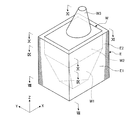
- FIG. 5 is a perspective view illustrating a state in which a three-dimensional object is formed using the support body illustrated in FIG. 4.
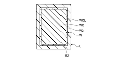
- 6 is a cross-sectional view taken along line VIII-VIII in FIG.
- FIG. 7 is a sectional view taken along line IX-IX in FIG.
- FIG. 8 is a cross-sectional view taken along line XX in FIG.
- FIG. 9 is a sectional view taken along line XI-XI in FIG.
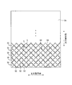
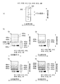
- FIG. 10 is a plan view illustrating an example of a printing pass for nozzle discharge control of the three-dimensional object formation method according to the embodiment.
- FIG. 11 is a diagram illustrating nozzle discharge control of the three-dimensional object formation method according to the embodiment.
- FIG. 11A is a diagram illustrating an example of the configuration of the ejection unit.
- FIG. 11B is a diagram illustrating an example of a method for ejecting ink a plurality of times at each position on the work surface.
- FIG. 12 is a diagram illustrating an example of correspondence between the nozzles of the discharge unit and the print path in the nozzle discharge control of the three-dimensional object formation method according to the embodiment.
- FIG. 12A is a diagram illustrating nozzles divided into ink discharge regions.
- FIG. 12B is a diagram illustrating an example of a change in the boundary of the print path according to a change in the position of each ink ejection region.
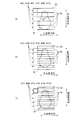
- FIG. 13 is a plan view illustrating an example of a printing path for nozzle discharge control in the three-dimensional object formation method according to Modification Example 1 of the embodiment.
- FIG. 14 is a diagram illustrating nozzle discharge control of the three-dimensional object formation method according to Modification Example 2 of the embodiment.
- Drawing 15 is a figure explaining the unit layer formation process of the solid thing modeling method concerning modification 3 of an embodiment.
- Fig.15 (a) is a top view explaining the state which forms the nth layer L in the unit layer formation process of the three-dimensional object modeling method which concerns on the modification 3 of embodiment
- FIG.15 (b) FIG. 15C is a plan view for explaining a state in which the (n + 1) th layer L is formed in the unit layer forming step of the three-dimensional object formation method according to the third modification of the embodiment
- FIG. It is a top view explaining the other example of the state which forms the n + 1st layer L in the unit layer formation process of the three-dimensional object modeling method which concerns.
- FIG. 1 is a schematic configuration diagram illustrating a schematic configuration of an inkjet printer according to an embodiment.
- FIG. 2 is an example of a flowchart of the three-dimensional object modeling method according to the embodiment.
- FIG. 3 is a perspective view showing an example of a three-dimensional object formed by the ink jet printer shown in FIG.
- FIG. 4 is a perspective view showing an example of a support body used when modeling the three-dimensional object shown in FIG. 3.
- FIG. 5 is a perspective view illustrating a state in which a three-dimensional object is formed using the support body illustrated in FIG. 4.
- 6 is a cross-sectional view taken along line VIII-VIII in FIG.
- FIG. 7 is a sectional view taken along line IX-IX in FIG.
- FIG. 8 is a cross-sectional view taken along line XX in FIG.
- FIG. 9 is a sectional view taken along line XI-XI in FIG.
- An inkjet printer 1 as a three-dimensional printer according to the embodiment shown in FIG. 1 uses a so-called inkjet method to manufacture a three-dimensional object W (an example is shown in FIG. 3) that is a three-dimensional three-dimensional object.
- the inkjet printer 1 typically divides the three-dimensional object W into a number of layers L (shown in FIG. 3) in the vertical direction based on the three-dimensional data indicating the shape and surface image of the three-dimensional object W.
- modeling materials tilting modeling materials (thinned inks) in order from the lower layer L based on the shape data indicating the shape of each layer L of the three-dimensional object W and the surface image data indicating the surface image.
- the three-dimensional object W is modeled according to the three-dimensional data.
- the three-dimensional object W includes a model portion WM that is modeled with white (W: White) ink, and a yellow (Y: Yellow) ink that is formed on the surface of the model portion WM. And a color portion WC composed of at least one of M: Magenta ink, cyan (C: Cyan) ink, and black (K) ink, and a transparent ink covering the color portion WC. It is comprised with the clear part WCL comprised.
- a solid object W shown as an example in FIG. 3 includes an enlarged portion W1 whose cross-sectional shape gradually increases as it goes upward in FIG. 3, and a rectangular parallelepiped portion that is connected to the upper end of the enlarged portion W1 in FIG.
- the enlarged portion W1 has a triangular cross section.
- the rectangular parallelepiped portion W2 has a rectangular cross-sectional shape.
- the projecting portion W3 has a circular cross-sectional shape and an outer appearance of a truncated cone shape.
- the shape of the three-dimensional object W is not limited to this.
- an inkjet printer 1 includes a mounting table 2 whose upper surface forms a work surface 2a (corresponding to a landing surface), a Y bar 3 provided in the main scanning direction (corresponding to the first direction), a carriage 4, a carriage driving unit 5 (corresponding to a relative movement unit), a mounting table driving unit 6 (corresponding to a relative movement unit), a control device 7, an input device 8, and the like.
- the work surface 2a of the mounting table 2 is formed flat in a horizontal direction (a direction parallel to both the X axis and the Y axis shown in FIG. 1), and ink as a modeling material is formed thereon from the lower layer L. It is a plane laminated in order.
- the mounting table 2 is formed in a substantially rectangular shape, for example, but is not limited thereto.
- the Y bar 3 is provided at a predetermined interval above the mounting table 2 in the vertical direction.
- the Y bar 3 is provided linearly along the main scanning direction parallel to the horizontal direction (Y axis).
- the Y bar 3 guides the reciprocation of the carriage 4 along the main scanning direction.
- the carriage 4 is held by the Y bar 3 and can reciprocate in the main scanning direction along the Y bar 3.
- the carriage 4 is controlled to move in the main scanning direction.
- the carriage 4 is provided with a support ink discharge unit 44, a plurality of discharge units 41, and an ultraviolet irradiator 42 on a surface facing the mounting table 2 in the vertical direction via a holder (not shown).
- the support ink discharge unit 44 discharges the support ink whose degree of cure is changed by exposure to the work surface 2a.
- the support ink discharge unit 44 of the embodiment can discharge at least the support ink that forms the support body E (shown in FIG. 4) along the outline of the three-dimensional object W as the ink whose degree of cure changes when exposed.
- the carriage drive unit 5 can move relative to the work surface 2a.
- the support body E is formed in the shape where the inner peripheral surface followed the outer surface of the three-dimensional object W. The support body E is used to support a certain layer L when the layer L of the three-dimensional object W is not present in the lower layer of the certain layer L in the stacking direction, or the outer surface of the three-dimensional object W is formed flat.
- the support body E has an enlarged inclined portion E1 having a shape along the outer surface of the enlarged portion W1 of the three-dimensional object W and a shape along the outer surface of the cuboid portion W2.
- the vertical portion E2 is integrally provided.
- the enlarged inclined part E1 supports the layer L of the three-dimensional object W
- the vertical part E2 is formed with a support body E for modeling the outer surface of the three-dimensional object W flatly.
- the support ink ejection unit 44 can reciprocate along the main scanning direction as the carriage 4 moves along the main scanning direction.
- the support ink discharge unit 44 is connected to an ink tank through various ink flow paths, a regulator, a pump, and the like.
- One or a plurality of support ink ejection units 44 are provided depending on the number of ink tanks, in other words, the number of types of support ink that can be ejected simultaneously.
- the support ink discharge unit 44 is an ink jet discharge unit that can discharge the support ink in the ink tank toward the work surface 2a by an ink jet method.
- the support ink whose degree of cure changes by exposure for example, UV (UltraViolet) cured ink that is cured by irradiating ultraviolet rays can be used.
- the UV effect ink desirably has water solubility, alcohol solubility, or heat solubility after curing.
- the support ink discharge unit 44 is electrically connected to the control device 7, and the drive thereof is controlled by the control device 7.
- the ejection unit 41 ejects ink as a modeling material for modeling the three-dimensional object W whose degree of curing changes by exposure to the work surface 2a.
- the discharge unit 41 of the embodiment is capable of discharging at least ink whose degree of cure is changed by exposure to the work surface 2 a and is relatively movable with respect to the work surface 2 a by the carriage drive unit 5.
- the ejection unit 41 can reciprocate along the main scanning direction as the carriage 4 moves along the main scanning direction.
- the ejection unit 41 is connected to an ink tank through various ink flow paths, a regulator, a pump, and the like.
- the ejection units 41 are provided according to the number of ink tanks, in other words, the types of ink colors that can be ejected simultaneously.
- the ejection unit 41 includes an ejection unit 41Y that ejects yellow (Y) ink, an ejection unit 41M that ejects magenta (M) ink, and a cyan (C) ink.
- a discharge unit 41C that discharges ink, a discharge unit 41K that discharges black (K) ink, a discharge unit 41W that discharges white (W) ink, and a discharge unit that discharges clear (CL) ink 41CL.
- the ejection units 41Y, 41M, 41C, 41K, 41W, and 41CL are inkjet ejection units that can eject ink in the ink tank toward the work surface 2a by an inkjet method.
- an ink that can be used can be UV (ultraviolet) curable ink that is cured by irradiating ultraviolet rays.
- the discharge units 41Y, 41M, 41C, 41K, 41W, and 41CL are electrically connected to the control device 7, and their driving is controlled by the control device 7.
- the discharge units 41Y, 41M, 41C, 41K, 41W, and 41CL are arranged in the Y-axis direction.
- the ink jet printer 1 includes the ejection units 41Y, 41M, 41C, 41K, 41W, and 41CL, thereby ejecting at least three primary color inks.
- the discharge units 41Y, 41M, 41C, 41K, 41W, 41CL and the support ink discharge unit 44 are a plurality of nozzles arranged at a constant density in the sub-scanning direction (corresponding to the second direction). 302.
- the ejection units 41Y, 41M, 41C, 41K, 41W, 41CL and the support ink ejection unit 44 form the three-dimensional object W and the support body E by ejecting ink from these nozzles 302 while moving in the main scanning direction. To do.
- each of the ejection units 41Y, 41M, 41C, 41K, 41W, 41CL and the support ink ejection unit 44 includes the plurality of nozzles 302 arranged at a constant density in the sub-scanning direction.
- a plurality of nozzle rows 303 composed of a plurality of nozzles 302 arranged in the scanning direction are provided.
- the nozzle density d in which the nozzles 302 are arranged is smaller than the printing resolution. Therefore, a desired print resolution can be obtained by forming the same position on the work surface 2a a plurality of times by a plurality of print passes.
- the ejection portions 41Y, 41M, 41C, 41K, 41W, and 41CL and the support ink ejection portion 44 are equivalent to the band width that is the width of the printing pass 50 (shown in FIG. 10) that is shorter than the length of the nozzle row 303 in the sub-scanning direction.
- the ultraviolet irradiator 42 gives an external stimulus to the ink ejected on the work surface 2a and the support ink.
- the ultraviolet irradiator 42 is configured to irradiate ultraviolet rays (UV) to the ink and support ink ejected on the work surface 2a, and irradiates the ink and support ink ejected on the work surface 2a with ultraviolet rays. Thus, the ink and the support ink are exposed.
- the ultraviolet irradiator 42 is constituted by, for example, an LED module that can irradiate ultraviolet rays.
- the ultraviolet irradiator 42 is provided on the carriage 4 and can reciprocate along the main scanning direction as the carriage 4 moves along the main scanning direction.
- the ultraviolet irradiator 42 is electrically connected to the control device 7, and its drive is controlled by the control device 7.
- the carriage drive unit 5 reciprocally moves the carriage 4, that is, the ejection units 41Y, 41M, 41C, 41K, 41W, and 41CL, the support ink ejection unit 44, and the ultraviolet irradiator 42 relative to the Y bar 3 in the main scanning direction. It is a drive device.
- the carriage drive unit 5 includes, for example, a transmission mechanism such as a conveyance belt connected to the carriage 4 and a drive source such as an electric motor that drives the conveyance belt.
- the carriage drive unit 5 converts the power generated by the drive source into power for moving the carriage 4 along the main scanning direction via the transmission mechanism, and reciprocates the carriage 4 along the main scanning direction.
- the carriage drive unit 5 is electrically connected to the control device 7, and its drive is controlled by the control device 7.
- the carriage driving unit 5 and the mounting table driving unit 6 are configured to relatively move the discharge units 41Y, 41M, 41C, 41K, 41W, and 41CL and the work surface 2a.
- the mounting table driving unit 6 includes a vertical direction moving unit 61, a sub-scanning direction moving unit 62, and an axis rotation unit 63.
- the vertical direction moving unit 61 moves the mounting table 2 up and down along a vertical direction parallel to the Z axis, thereby moving the work surface 2a formed on the mounting table 2 to the discharge units 41Y, 41M, 41C, 41K, and 41W.
- 41CL, the support ink discharge part 44 and the ultraviolet irradiator 42 are moved up and down relatively along the vertical direction.
- the mounting table drive unit 6 moves the work surface 2a closer to and away from the discharge units 41Y, 41M, 41C, 41K, 41W, and 41CL, the support ink discharge unit 44, and the ultraviolet irradiator 42 along the vertical direction. be able to. That is, the mounting table drive unit 6 enables the work surface 2a to move relative to the ejection units 41Y, 41M, 41C, 41K, 41W, and 41CL, the support ink ejection unit 44, and the ultraviolet irradiator 42 along the vertical direction. .
- the sub-scanning direction moving unit 62 moves the mounting table 2 in the sub-scanning direction parallel to the X axis orthogonal to the main scanning direction, thereby causing the work surface 2a formed on the mounting table 2 to be ejected by the discharge units 41Y, 41Y, 41M, 41C, 41K, 41W, 41CL, the support ink discharge unit 44, and the ultraviolet irradiator 42 are relatively reciprocated along the sub-scanning direction.
- the mounting table drive unit 6 reciprocates along the sub-scanning direction along the sub-scanning direction with respect to the discharge units 41Y, 41M, 41C, 41K, 41W, and 41CL, the support ink discharge unit 44, and the ultraviolet irradiator 42. Can be made.
- the sub-scanning direction moving unit 62 reciprocally moves the discharge units 41Y, 41M, 41C, 41K, 41W, and 41CL, the support ink discharge unit 44, the ultraviolet irradiator 42, and the work surface 2a relatively in the sub-scanning direction.
- the sub-scanning direction moving unit 62 moves the mounting table 2 in the sub-scanning direction.
- the present invention is not limited to this, and for each Y bar 3, the discharge units 41Y, 41M, 41C, and 41K. , 41W, 41CL, the support ink discharge unit 44, and the ultraviolet irradiator 42 may be moved in the sub-scanning direction.
- the axial center rotation unit 63 rotates the mounting table 2 around an axis (Z axis) parallel to the vertical direction, so that the work surface 2a formed on the mounting table 2 is discharged to the discharge units 41Y, 41M, 41C, and 41K. , 41W, 41CL, the support ink discharge unit 44, and the ultraviolet irradiator 42 are rotated relatively around the axis.
- the mounting table driving unit 6 can rotate the work surface 2a about the axis with respect to the ejection units 41Y, 41M, 41C, 41K, 41W, and 41CL, the support ink ejection unit 44, and the ultraviolet irradiator 42. it can.
- the shaft center rotating unit 63 rotates the discharge units 41Y, 41M, 41C, 41K, 41W, and 41CL, the support ink discharge unit 44, the ultraviolet irradiator 42, and the work surface 2a around an axis parallel to the vertical direction. Make it free.
- the control device 7 controls each part of the inkjet printer 1 including the ejection units 41Y, 41M, 41C, 41K, 41W, and 41CL, the support ink ejection unit 44, the ultraviolet irradiator 42, the carriage driving unit 5, the mounting table driving unit 6, and the like. To do.
- the control device 7 is composed of hardware such as an arithmetic device and a memory, and a program for realizing these predetermined functions.
- the control device 7 controls the ejection units 41Y, 41M, 41C, 41K, 41W, and 41CL and the support ink ejection unit 44, and inks of the ejection units 41Y, 41M, 41C, 41K, 41W, and 41CL, and the support ink ejection unit 44.
- the discharge amount, discharge timing, discharge period, and the like are controlled.
- the control device 7 controls the ultraviolet irradiator 42 to control the intensity of ultraviolet light to be irradiated, the exposure timing, the exposure period, and the like.
- the control device 7 controls the carriage driving unit 5 and controls the relative movement of the carriage 4 along the main scanning direction.
- the control device 7 controls the mounting table driving unit 6 to control the relative movement of the mounting table 2 in the vertical direction and the sub-scanning direction and the relative movement around the axis.
- the control device 7 includes a slice module 71 that divides the three-dimensional data input from the input device 8 into each layer L, calculates cross-sectional slice information of each layer L, and an output module 72 that analyzes the cross-sectional slice information. ing.
- the input device 8 is connected to the control device 7 and inputs three-dimensional data indicating the shape and surface image of the three-dimensional object W.
- the input device 8 includes, for example, a PC connected to the control device 7 by wire / wireless, various terminals, and the like.
- FIGS. 10 to 12 are also referred to as appropriate. 10 to 12 are diagrams for explaining an example of the three-dimensional object formation method according to the embodiment.
- the three-dimensional object modeling method of the embodiment is a method for manufacturing a three-dimensional object W.
- This three-dimensional object modeling method is performed by controlling the drive of each part of the inkjet printer 1 by the control device 7 of the inkjet printer 1.
- the three-dimensional data including the three-dimensional object W and the support body E is divided into a plurality of layers L and EL, and the slice information of the three-dimensional object W of each layer L and EL and the slice information of the support body E are obtained.
- each layer L using a plurality of printing paths 50, while moving the discharge units 41Y, 41M, 41C, 41K, 41W, 41CL, the support ink discharge unit 44, and the ultraviolet irradiator 42 in the main scanning direction.
- EL is formed.
- the three-dimensional object modeling method of the present embodiment employs multi-pass recording in which ink and support ink are ejected a plurality of times from the nozzle 302 at each position of the so-called layers L and EL.
- the operation surface 2a is moved in the sub-scanning direction by a band width equal to the width of the printing pass 50, and the ejection units 41Y, 41M, 41C, 41K, 41W, 41CL, and the discharge of the support ink
- the solid object W is formed by repeating the operation of discharging the ink and the support ink while moving the unit 44 and the ultraviolet irradiator 42 in the main scanning direction.
- the three-dimensional data of the three-dimensional object W input from the input device 8 is read by the control device 7 connected to the input device 8 (step ST21).
- the three-dimensional data includes shape data and surface image data.
- the shape data is data for specifying the shape of the three-dimensional object W, and is data indicating coordinates on the X-axis, Y-axis, and Z-axis of the micro area on the surface of the three-dimensional object W, that is, three-dimensional coordinate data. It is configured.
- the surface image data is data indicating an image (color) of the surface of the three-dimensional object W, and indicates an image profile of each minute region of the shape data.
- the image profile indicates the darkness of each color of yellow (Y), magenta (M), cyan (C), and black (K) in, for example, 256 gradations or 65536 gradations.
- the control device 7 calculates and generates the shape data of the support body E based on the three-dimensional data. Then, the slice module 71 of the control device 7 determines the three-dimensional object W and the three-dimensional object W based on the shape data of the three-dimensional data and the size of the ink droplets of the ink ejected by the ejection units 41Y, 41M, 41C, 41K, 41W, 41CL. The number N of layers L and EL dividing the three-dimensional data of the support body E in the Z-axis direction is calculated (step ST22).
- the slice module 71 of the control device 7 calculates the height of the three-dimensional object W and the support body E in the Z-axis direction based on the shape data, and uses the calculated height as the size of the ink droplet of ink.
- the number N of layers L is calculated by dividing by the height according to.
- the slice module 71 of the control device 7 partitions the three-dimensional data into a plurality of layers L, and in each of the partitioned layers L and EL (the first week of the loop from step ST23 to step ST29) A slice information calculation step (step ST23) for calculating cross-sectional slice information of the layers L and EL) is executed.
- the slice slice 71 of the control device 7 calculates the slice information of the layers L and EL calculated in the slice information calculation step (step ST23) according to the size of the ink droplets of the ink ejected by the ink jet printer 1 from the three-dimensional data. It is divided into a plurality of layers L and EL having a height.
- cross-sectional slice information of the lowermost layers L and EL is calculated.
- the cross-sectional slice information indicates three-dimensional coordinate data indicating coordinates on the X-axis, Y-axis, and Z-axis of each minute region of each layer L, and an image profile of each minute region of each layer L, that is, surface image data.
- the output module 72 analyzes the cross-sectional slice information of the three-dimensional object W and the cross-sectional slice information of the support body E (step ST24). Specifically, the output module 72, based on the cross-sectional slice information of the three-dimensional object W, the area in the XY plane of the model portion WM of each layer L formed by the cross-sectional slice information, the thickness of the color portion WC, and the clear portion WCL. (Length in the sub-scanning direction) and the like are calculated.
- the output module 72 determines the angle of the portion that forms the outer surface of the three-dimensional object W composed of the plurality of layers EL with respect to the XY plane, based on the cross-sectional slice information of the plurality of support bodies E that are continuous in the Z-axis direction. It is calculated whether the three-dimensional object W exists above each layer EL in the stacking direction.
- the area of the model portion WM in the XY plane, the thickness of the collar portion WC, and the clear portion WCL correspond to the section slice information portion.
- control device 7 calculates whether or not the nozzle discharge control is performed based on the cross-sectional slice information calculated in the slice information calculation step (step ST23) and analyzed in step ST24.
- the process determination process (step ST25) determined every time is performed.
- the nozzle discharge control is control for suppressing the generation of streaks parallel to the main scanning direction on the surface of the three-dimensional object W (that is, banding).
- the control device 7 (1) When the area of the model portion WM on the XY plane is equal to or larger than a predetermined value, it is determined that the nozzle discharge control is performed (necessary) when forming the model portion WM; (2) When the thickness (length in the sub-scanning direction) of the color portion WC and the clear portion WCL is equal to or greater than a predetermined value, it is determined that the nozzle discharge control is performed when forming the color portion WC and the clear portion WCL.
- the inner surface of the enlarged inclined portion E1 of the support body E has an angle with respect to the XY plane that is equal to or smaller than a predetermined value, and a solid object W is formed on the inner surface.
- the control device 7 is configured so that the stacking direction (Z direction) can be achieved even when the angle of the portion forming the outer surface of the three-dimensional object W in the plurality of layers EL of the support body E with respect to the XY plane is larger than a predetermined value.
- step ST25 The control device 7 (1) When the area of the model portion WM in the XY plane is less than a predetermined value, it is determined that the nozzle discharge control is not performed (not required) when forming the model portion WM; (2) When the thickness of the color part WC and the clear part WCL is less than a predetermined value, it is determined that the nozzle discharge control is not performed when forming the color part WC and the clear part WCL. (3) When the gradation of the image profile of the color portion WC is less than a predetermined gradation, that is, when the color of the color portion WC is light, it is determined that the nozzle discharge control is not performed when the color portion WC is formed.
- the control device 7 determines whether or not to perform the nozzle discharge control based on the surface image data included in the slice slice information in the process determination step (step ST25). .
- the area of the model portion WM on the XY plane is often greater than or equal to a predetermined value (because it is), so when forming the model portion WM, the control device 7 is often determined (determined) that the nozzle discharge control is performed.
- the control device 7 since the thickness of the color part WC and the clear part WCL is often less than a predetermined value (there is), when forming the color part WC and the clear part WCL, the control device 7 In many cases, it is determined that the discharge control is not performed (determined). In the present embodiment, the angle of the portion forming the outer surface of the three-dimensional object W composed of the plurality of layers EL of the support body E with respect to the XY plane exceeds a predetermined value. When the layer L of the three-dimensional object W is not formed on the layer EL at the uppermost position of the vertical portion E2, the control device 7 performs the nozzle discharge control when forming each layer EL of the support body E. Judged as none.
- the support body E a surface that is nearly perpendicular to the XY plane is formed, and when the layer L of the three-dimensional object W is not formed on the layer EL of the vertical portion E2 of the support body E, the support body This is because the banding generated in E does not affect the three-dimensional object W.
- each nozzle ejection control is performed for each ejection section 41Y, 41M, 41C, 41K, 41W, 41CL and the support ink ejection section 44, that is, for each nozzle row 303.
- ink is ejected a plurality of times from the plurality of nozzles 302 arranged in the sub-scanning direction of the ejection sections 41Y, 41M, 41C, 41K, 41W, and 41CL and the support ink ejection section 44, and each position of each layer L and EL
- each layer L is formed by a plurality of printing passes 50, and the printing passes 50 are set so that the boundary 52 between the printing passes 50 extends obliquely with respect to the main scanning direction (see FIG. 10).
- pass positions 404a to 404e that are positions of a plurality of print passes 50 (shown in FIG. 10) are set.
- the width of each pass position 404a to 404e in the sub-scanning direction is equal to the bandwidth.
- the printing pass 50 has a wave shape that swings back and forth in the sub-scanning direction. Therefore, the wavy path positions 404a to 404e are set according to the print path 50.
- the path positions 404a to 404e are shown in a rectangular shape in order to simplify the illustration.
- FIG. 11B the path positions 404a to 404e are shown in a rectangular shape in order to simplify the illustration.
- FIG. 10 is a plan view illustrating an example of a printing pass for nozzle discharge control of the three-dimensional object formation method according to the embodiment.
- FIG. 11 is a diagram illustrating nozzle discharge control of the three-dimensional object modeling method according to the embodiment
- FIG. 11A is a diagram illustrating an example of the configuration of the discharge unit
- FIG. It is a figure which shows an example of the method of discharging an ink in multiple times to each position of the surface.
- the ejection units 41Y, 41M, 41C, 41K, 41W, and 41CL and the support ink ejection unit 44 print the positions of the layers L and EL through the four printing passes 50. Therefore, the ejection portions 41Y, 41M, 41C, 41K, 41W, 41CL and the support ink ejection portion 44 are divided into at least four ink ejection regions 402a to 402d in the sub-scanning direction. The width of each ink ejection region 402a-d in the sub-scanning direction is equal to the bandwidth.
- the boundaries of the ink ejection regions 402a to 402d are changed according to the positions of the ejection units 41Y, 41M, 41C, 41K, 41W, and 41CL and the support ink ejection unit 44 in the main scanning direction. Accordingly, the ejection units 41Y, 41M, 41C, 41K, 41W, and 41CL and the support ink ejection unit 44 eject ink and support ink in accordance with the wavy print path 50.
- the nozzle discharge control will be described in more detail while showing the positional relationship among the discharge units 41Y, 41M, 41C, 41K, 41W, 41CL and the support ink discharge unit 44 and the work surface 2a.
- ink and support ink are ejected to the pass positions 404a to 404e, for example, when the positions in the sub-scanning direction of the pass position 404a and the ink ejection area 402a first overlap, for example, printing corresponding to the pass position 404a is performed.
- a print area including the pass 50 and the other three print passes 50 is set.
- the ejection units 41Y, 41M, 41C, 41K, 41W, 41CL and the support ink ejection unit 44 move in the main scanning direction (FIG. 11B). By this movement, ink and support ink are ejected from the ejection region 41a in the ejection units 41Y, 41M, 41C, 41K, 41W, and 41CL and the support ink ejection unit 44 to the pass position 404a.
- the sub-scanning direction moving unit 62 moves the work surface 2a in the sub-scanning direction by the bandwidth.
- the positions of the pass positions 404a and 404b in the sub-scanning direction overlap with the ink discharge areas 402b and 402a, respectively.
- a print area including the print path 50 corresponding to the pass positions 404a and 404b and the other two print paths 50 is set.
- the ejection units 41Y, 41M, 41C, 41K, 41W, 41CL and the support ink ejection unit 44 move in the main scanning direction (FIG. 11B).
- ink is ejected from the ejection regions 41a, 402M, 41C, 41K, 41W, 41CL and the ejection regions 402a, 402b in the support ink ejection unit 44 to the pass positions 404b, 404a.
- the sub-scanning direction moving unit 62 further moves the work surface 2a corresponding to the band width.
- the positions of the pass positions 404a to 404c in the sub-scanning direction overlap with the ink discharge areas 402c to 402a, respectively.
- a print area including the print path 50 corresponding to the pass positions 404a to 404c and another print path 50 is set.
- the ejection units 41Y, 41M, 41C, 41K, 41W, 41CL and the support ink ejection unit 44 move in the main scanning direction (FIG. 11B).
- ink is ejected from the ink ejection regions 402a to 402c in the ejection units 41Y, 41M, 41C, 41K, 41W, and 41CL and the support ink ejection unit 44 to the pass positions 404c to 404a.
- the sub-scanning direction moving unit 62 further conveys the work surface 2a by the bandwidth.
- the positions of the pass positions 404a to 404d in the sub-scanning direction overlap with the ink discharge areas 402d to 402a, respectively.
- a print area including the print pass 50 corresponding to the pass positions 404a to 404d is set.
- the ejection units 41Y, 41M, 41C, 41K, 41W, 41CL and the support ink ejection unit 44 move in the main scanning direction (FIG. 11B).
- ink is ejected from the ink ejection regions 402a to 402d in the ejection units 41Y, 41M, 41C, 41K, 41W, and 41CL and the support ink ejection unit 44 to the pass positions 404d to 404a.
- FIG. 12 shows an example of the correspondence between the ejection sections 41Y, 41M, 41C, 41K, 41W, and 41CL and the nozzles 302 of the support ink ejection section 44 and the print path 50.
- FIG. 12A shows the arrangement of the nozzles 302 divided into the ink ejection regions 402a to 402d.
- the nozzles 302 arranged in the sub-scanning direction are distributed to the dummy nozzle area 406a, the ink ejection areas 402a to 402d, and the dummy nozzle area 406b.
- Each of the ink ejection regions 402a to 402d includes the same number of nozzles 302.
- the nozzles 302 included in each of the ink ejection regions 402a to 402d are respectively associated with the four print passes 50 that are simultaneously formed.
- the nozzles 302 included in the respective ranges of the ink discharge regions 402a to 402d are selected as the nozzles 302 that should eject ink droplets to each of the four print paths 50 included in the print region.
- the nozzles 302 included in the dummy nozzle regions 406a and 406b are set as dummy nozzles that do not eject ink.
- the range of the nozzles 302 selected corresponding to each printing pass 50 is sequentially changed according to the positions of the ejection units 41Y, 41M, 41C, 41K, 41W, 41CL and the support ink ejection unit 44 in the main scanning direction. To do.
- the ranges of the dummy nozzle areas 406a and 406b are changed in accordance with the change of the positions of the ink discharge areas 402a to 402d. In this way, it is possible to shift the positions of the ink ejection regions 402a to 402d while maintaining the respective sizes.
- the number of nozzles 302 is shown in a simplified manner.
- Each of the ink ejection regions 402a to 402d and the dummy nozzle regions 406a and 406b include, for example, more nozzles 302 than illustrated.
- FIG. 12B shows an example of the change in the boundary 52 of the print path 50 in accordance with the change in the position of each of the ink ejection regions 402a to 402d.
- the boundary 52 of the printing pass 50 is also shifted stepwise in the sub-scanning direction accordingly. Therefore, according to the present embodiment, the ejection units 41Y, 41M, 41C, 41K, 41W, and 41CL are moved while moving the ejection units 41Y, 41M, 41C, 41K, 41W, and 41CL and the support ink ejection unit 44 in the main scanning direction.
- the position of the boundary 52 of the printing pass 50 can be changed according to the position of the support ink discharge unit 44.
- the boundary 52 of the printing pass 50 is sequentially shifted in a step shape. Therefore, the boundary 52 extends in a polygonal line in an oblique direction with respect to the main scanning direction. Accordingly, the print path 50 is set so that the boundary 52 of the print path 50 extends in an oblique direction with respect to the main scanning direction.
- the boundary 52 of the print pass 50 can be wave-shaped that swings back and forth in the sub-scanning direction. Therefore, according to the present embodiment, for example, the wavy print path 50 as described with reference to FIG. 10 can be appropriately set.
- the direction in which the boundary 52 between the print passes 50 is shifted is reversed between the layers L and EL that overlap each other in the stacking direction.
- the boundary 52 between the print paths 50 is formed so as to extend in a polygonal line in a diagonal direction with respect to the main scanning direction.
- the boundary 52 between the print passes 50 is slanted in the direction opposite to the odd-numbered layers L and EL with respect to the main scanning direction, as indicated by a thick solid line in FIG.
- the print path 50 is set so as to extend in the direction.
- the print path 50 is formed so that at least a part of the boundary 52 between the print paths 50 is shifted in the sub-scanning direction between the adjacent layers L and EL in the stacking direction of the layers L and EL. To do.
- control device 7 when the control device 7 forms the model portion WM, the color portion WC, the clear portion WCL, and each layer EL of the support body E of each layer L that is determined not to perform nozzle discharge control, the control device 7 may The print pass 50 is set so that the boundary 52 extends in parallel with the main scanning direction.
- the output module 72 causes the discharge units 41 ⁇ / b> Y and 41 ⁇ / b> M for each layer L of the three-dimensional object W based on the presence / absence of nozzle discharge control and cross-sectional slice information in the process determination step (step ST ⁇ b> 25).
- 41C, 41K, 41W, and 41CL are generated, and discharge control amounts, curing control amounts, control amounts of the carriage drive unit 5 and the mounting table drive unit 6 that can realize the generated discharge patterns are generated.
- control device 7 discharges the support ink discharge portion 44 for each layer EL of the support body E based on the presence / absence of the nozzle discharge control and the cross-sectional slice information of the support body E in the process determination step (step ST25).
- a pattern is generated, and a discharge control amount, a curing control amount, a control amount of the carriage drive unit 5 and the mounting table drive unit 6 that can realize the generated discharge pattern are generated.
- the control device 7 determines that the nozzle discharge control is performed, the discharge of each of the discharge units 41Y, 41M, 41C, 41K, 41W, 41CL and the support ink discharge unit 44 for performing the nozzle discharge control is performed. A pattern is generated, and a discharge control amount, a curing control amount, a control amount of the carriage drive unit 5 and the mounting table drive unit 6 that can realize the generated discharge pattern are generated. In addition, when it is determined that the nozzle discharge control is not performed, the control device 7 sets the discharge patterns of the discharge units 41Y, 41M, 41C, 41K, 41W, and 41CL and the support ink discharge unit 44 that do not perform the nozzle discharge control. And generating a discharge control amount, a curing control amount, a control amount of the carriage drive unit 5 and the mounting table drive unit 6 that can realize the generated discharge pattern.
- the output module 72 enables the ejection control amount, the curing control amount, and the carriage drive that can realize the ejection patterns of the ejection units 41 Y, 41 M, 41 C, 41 K, 41 W, and 41 CL and the support ink ejection unit 44.
- the control amount of the unit 5 and the mounting table driving unit 6 is transferred to the carriage driving unit 5, the mounting table driving unit 6, the ejection units 41Y, 41M, 41C, 41K, 41W, and 41CL, the support ink ejection unit 44, and the ultraviolet irradiator 42. Transmit (step ST26).
- control device 7 performs a unit layer forming step (step ST27) in which the ink jet printer 1 forms the layers L and EL based on the cross-sectional slice information of the three-dimensional object W and the cross-sectional slice information of the support body E.
- the control device 7 includes the mounting units 41Y, 41M, 41C, 41K, 41W, and 41CL, the support ink discharging unit 44, and the ultraviolet irradiator 42 according to the generated discharging pattern.
- the mounting table 2 is moved to the ejection units 41Y, 41M, 41C, 41K, 41W, 41CL, the support ink ejection unit 44, and the ultraviolet irradiator 42.
- the ink and the support ink are discharged from the discharge portions 41Y, 41M, 41C, 41K, 41W, and 41CL and the support ink discharge portion 44 to the work surface 2a while being rotated relatively in the sub-scanning direction and the axis.
- the discharged ink is exposed to ultraviolet rays irradiated from the ultraviolet irradiator 42 to form the layers L and EL.
- the unit layer forming process includes a printing process (step ST27A) and a sub-scanning direction moving process (step ST27B).
- the control device 7 controls the carriage driving unit 5, the vertical direction moving unit 61, and the axial center rotating unit 63 to position the carriage 4 at an appropriate position with respect to the work surface 2a. Then, the control device 7 moves the carriage 4 in the main scanning direction by the carriage drive unit 5, and discharge units 41 Y, 41 M, 41 C, 41 K, 41 W, 41 CL attached to the carriage 4, the support ink discharge unit 44, and the like.
- the ultraviolet irradiator 42 is moved in the main scanning direction.
- the control device 7 moves the ejection units 41Y, 41M, 41C, 41K, 41W, and 41CL, the support ink ejection unit 44, and the ultraviolet irradiator 42 in the main scanning direction, and generates each layer L generated in the ejection pattern generation process.
- Ink and support ink are discharged from the discharge portions 41Y, 41M, 41C, 41K, 41W, and 41CL and the support ink discharge portion 44 at an appropriate timing for forming the EL.
- the ultraviolet irradiator 42 irradiates ultraviolet rays.
- the ejected ink and the support ink land on the work surface 2a or the shaped layers L and EL and are cured.
- the control device 7 discharges ink and support ink from the discharge portions 41Y, 41M, 41C, 41K, 41W, and 41CL and the support ink discharge portion 44 while moving the carriage 4 one or more times in the main scanning direction.
- the cured ink and the support ink are exposed and cured by the ultraviolet rays irradiated from the ultraviolet irradiator 42 to form one row of printing paths 50 in the main scanning direction of the layers L and EL.
- step ST27B the control device 7 controls the sub-scanning direction moving unit 62 to move the mounting table 2 in the sub-scanning direction by 50 printing lines for one row, and the sub-scanning direction.
- the discharge portions 41Y, 41M, 41C, 41K, 41W, 41CL, the support ink discharge portion 44, the ultraviolet irradiator 42, and the work surface 2a are relatively moved.
- the control device 7 determines whether or not the formation of each of the layers L and EL has been completed (step ST27C), and determines that the formation has not ended (step ST27C: No), and then proceeds to the printing process (step ST27A). Return.
- step ST27 the control device 7 forms a plurality of printing passes 50 by alternately performing the printing step (step ST27A) and the sub-scanning direction moving step (step ST27B) to form each layer L,
- step ST27C the modeling of each layer L and the entire EL is finished.
- the layers L and EL are determined based on the cross-sectional slice information of the three-dimensional object W and the cross-sectional slice information of the support body E determined to be subjected to nozzle discharge control in the processing determination step (step ST25).
- nozzle discharge control is performed.
- this unit layer forming step (step ST27) when nozzle ejection control is performed, at least part of the boundary 52 between the print paths 50 between the adjacent layers L and EL in the stacking direction of the layers L and EL is in the sub-scanning direction.
- the printing pass 50 is formed so as to be shifted to
- the layer L is based on the cross-sectional slice information of the three-dimensional object W and the cross-sectional slice information of the support body E that are determined not to perform the nozzle discharge control in the processing determination step (step ST25).
- the print path 50 is formed such that the boundary 52 between the print paths 50 is parallel to the main scanning direction without performing the nozzle ejection control.
- step ST29: No the control device 7 determines that n does not exceed N (step ST29: No)
- the control device 7 returns to the slice information calculation step (step ST23), and cross-sectional slice information and support of the three-dimensional object W of the next layer L and EL.
- the vertical movement unit 61 is controlled to lower the work surface 2a by one layer L and EL, so that the vertical position of the work surface 2a is the next layer L and EL. The position is appropriate for modeling.
- control device 7 analyzes the cross-sectional slice information of the three-dimensional object W and the cross-sectional slice information of the support body E (step ST24), determines the presence / absence of nozzle discharge control (step ST25), generates a discharge pattern, and the like.
- the ejection pattern or the like is transmitted to the ejection units 41Y, 41M, 41C, 41K, 41W, 41CL, the support ink ejection unit 44, the ultraviolet irradiator 42, and the like (step ST26).
- the control device 7 moves the ejection units 41Y, 41M, 41C, 41K, 41W, 41CL, the support ink ejection unit 44, and the ultraviolet irradiator 42 in the main scanning direction according to the generated ejection pattern, and Ink and support ink are ejected from the ejection units 41Y, 41M, 41C, 41K, 41W, and 41CL and the support ink ejection unit 44 to the work surface 2a while relatively rotating the mounting table 2 around the axis in the sub-scanning direction.
- the discharged ink and the support ink are exposed to the ultraviolet rays irradiated from the ultraviolet irradiator 42 to form the layers L and EL (step ST27).
- the control device 7 repeats the above-described process, that is, the unit layer forming process (step ST27) for each layer L and EL, so that the three-dimensional object W and the lower layer L and EL are sequentially formed as shown in FIG. A support body E is formed.
- step ST29: Yes the controller 7 completes the modeling of the three-dimensional object W, and removes the three-dimensional object W together with the support body E from the work surface 2a.
- the three-dimensional object shaping method is terminated.
- the solid object W that has been shaped is shaped into a shape defined by the shape data of the three-dimensional data, and an image defined by the surface image data is formed on the surface.
- the printing path 50 is formed so that at least a part of the printing path 50 is shifted in the sub-scanning direction between the layers L and EL that are stacked on each other.
- Each layer L, EL is formed.
- the boundary 52 between the print paths 50 can be suppressed from being continued in the stacking direction, and the three-dimensional object after modeling is formed. Generation of streaks parallel to the main scanning direction in W can be suppressed.
- the print path 50 is set so that the boundary 52 between the print paths 50 extends in an oblique direction with respect to the main scanning direction. Is inclined with respect to the main scanning direction, and even if a streak along the boundary 52 between the print passes 50 occurs, it can be made inconspicuous.
- the direction in which the boundary 52 of the print path 50 extends is different between the layers L and EL that are stacked on each other (between the layers L and EL adjacent to each other in the stacking direction). Yes.
- the direction in which the printing pass 50 is shifted in the sub-scanning direction is reversed between the layers L and EL that are stacked on each other. Therefore, in the inkjet printer 1 and the three-dimensional object modeling method, it is possible to suppress the generation of streaks parallel to the main scanning direction in the three-dimensional object W after modeling, and in particular, the upper surface of the three-dimensional object W after modeling. Etc. can be formed flat.
- the process determination step of determining whether or not the nozzle discharge control is performed for each of the slice slice information and the support body side slice information based on the slice slice information and the support body side slice information. (Step ST25).
- the nozzle discharge control can be performed or not performed according to the shape of each layer L, EL, the color density of the surface image, or the like. Therefore, in the inkjet printer 1 and the three-dimensional object modeling method, a three-dimensional object W with higher accuracy can be modeled.
- the printing pass 50 is set so that the printing pass 50 is parallel to the main scanning direction for a portion that is determined not to perform nozzle discharge control.
- the ejection units 41Y, 41M, 41C, 41K, 41W, 41CL and the support ink ejection unit 44 are ejected when ejecting the ink and the support ink along each printing path 50.
- Ink and support ink can be simultaneously discharged from as many nozzles as possible among the plurality of nozzles 302. Therefore, in the inkjet printer 1 and the three-dimensional object modeling method, the landing accuracy of the details of the three-dimensional object W can be improved, and precise modeling can be performed.
- the nozzle discharge control since the nozzle discharge control is performed in units of the nozzle row 303, whether or not the nozzle discharge control is performed can be set for each type of ink to be discharged and support ink. . For this reason, in the inkjet printer 1 and the three-dimensional object modeling method, whether or not nozzle discharge control is performed for each layer EL of the model portion WM, the color portion WC, the clear portion WCL, and the support body E of each layer L of the three-dimensional object W Is set. Therefore, in the inkjet printer 1 and the three-dimensional object modeling method, the nozzle discharge control can be appropriately performed in order to model the three-dimensional object W with higher accuracy.
- the inkjet printer 1 and the three-dimensional object modeling method determines whether or not the nozzle discharge control is performed based on the surface image data of the slice slice information. For this reason, for example, the nozzle discharge control is performed when the surface color of the three-dimensional object W is dark, and the nozzle discharge control is not performed when the color is thin. Whether or not the discharge control is performed can be appropriately determined. For this reason, in the inkjet printer 1 and the three-dimensional object modeling method, the ink landing accuracy can be improved in the light-colored portion of the surface of the three-dimensional object W, and the stripe parallel to the main scanning direction in the dark portion. Can be prevented from occurring.
- whether or not the nozzle discharge control is performed is determined based on the cross-sectional slice information of the support body E. For this purpose, for example, whether or not the nozzle discharge control is performed in each layer EL according to the angle of the portion forming the outer surface of the three-dimensional object W of the plurality of layers EL of the support body E with respect to the XY plane is appropriately determined. Can be determined.
- FIG. 13 is a plan view illustrating an example of a printing path for nozzle discharge control in the three-dimensional object formation method according to Modification Example 1 of the embodiment.
- the same parts as those in the above-described embodiment are denoted by the same reference numerals and description thereof is omitted.
- the control device 7 of the ink jet printer 1 as the three-dimensional printer according to the first modification of the embodiment discharges at each position of each layer L and EL in the unit layer forming step (step ST27).
- Ink is ejected a plurality of times from the plurality of nozzles 302 arranged in the sub-scanning direction of the portions 41Y, 41M, 41C, 41K, 41W, and 41CL and the support ink ejection unit 44, and the layers L and EL are formed by the plurality of printing passes 50. .
- the ejection units 41Y, 41M, 41C, 41K, 41W, and 41CL are arranged so that the width in the sub scanning direction of the printing pass 50 changes in the main scanning direction.
- the control which changes the discharge duty from the some nozzle 302 is performed during the movement of the main scanning direction of the support ink discharge part 44.
- the ejection duty indicates the number of nozzles 302 that simultaneously eject ink from each nozzle row 303.
- the ejection units 41Y, 41M, 41C, 41C, 41K, 41W, 41CL and the support ink ejection unit 44 are moved in the main scanning direction while moving the ejection units 41Y, 41M, 41C. , 41K, 41W, 41CL and the number of nozzles 302 that eject ink and support ink of the support ink ejection unit 44, the width of the print pass 50 in the sub-scanning direction is changed in the main scanning direction.
- the ejection units 41Y, 41M, 41C, 41K, 41W, 41CL and the ejection units 41Y, 41M, 41C, 41K, 41W, 41CL and the support ink ejection unit 44 are moved in the main scanning direction. Ink and support ink are ejected from the nozzle 302 located at the center in the sub-scanning direction of the support ink ejection unit 44, and the positions of the ejection units 41Y, 41M, 41C, 41K, 41W, 41CL and the support ink ejection unit 44 in the main scanning direction.
- the boundary 52 between the printing passes 50 is formed in a wave shape that swings back and forth in the sub-scanning direction.
- the cycle of the boundary 52 between the print passes 50 is shifted by about a half cycle between the layers L and EL that overlap each other.
- the print path 50 is set so that the boundary 52 between the print paths 50 is indicated by a thin solid line in FIG. 13, and in the even-numbered layers L and EL from the bottom, the print path 50 is set.
- a boundary 52 between 50 is set as shown by a thick solid line in FIG.
- the print path 50 is formed so that at least a part of the boundary 52 between the print paths 50 is shifted in the sub-scanning direction between the adjacent layers L and EL in the stacking direction of the layers L and EL. Is done.
- the nozzle discharge control when the nozzle discharge control is not performed, as many nozzles 302 as possible (preferably all the nozzles 302) of the discharge units 41Y, 41M, 41C, 41K, 41W, and 41CL and the support ink discharge unit 44 are used. ) To eject ink and support ink to form the layers L and EL.
- the print path 50 is set so that the width of the print path 50 in the sub-scanning direction changes in the main scanning direction.
- the boundary 52 between them is slanted with respect to the main scanning direction, and even if a streak along the boundary 52 between the print passes 50 occurs, it can be made inconspicuous.
- the ejection portions 41Y, 41M, 41C, 41K, 41W, and 41CL and the support ink ejection portion 44 are ejected between the layers L and EL that are stacked on each other.
- the duty cycle is shifted.
- the inkjet printer 1 and the three-dimensional object modeling method of Modification 1 can suppress the generation of streaks parallel to the main scanning direction in the three-dimensional object W after modeling, In particular, the upper surface of the three-dimensional object W can be formed flat.
- FIG. 14 is a diagram illustrating nozzle discharge control of the three-dimensional object formation method according to Modification Example 2 of the embodiment.
- the same parts as those in the above-described embodiment are denoted by the same reference numerals and description thereof is omitted.
- the slice information of the second layer L is calculated.
- the process determination step (step ST25) when determining whether or not to perform nozzle discharge control for each section slice information portion, as illustrated in FIG.
- the cross-sectional slice information of the n-th layer L is compared with the cross-sectional slice information of the (n + 1) -th layer L to be shaped one after. Then, a region R (shown by parallel oblique lines in FIG.
- the inkjet printer 1 and the three-dimensional object modeling method of Modification 2 it is possible to suppress the generation of streaks parallel to the main scanning direction in the three-dimensional object W after modeling as in the embodiment.
- the region R that overlaps the cross-sectional slice information of the (n + 1) th layer L that is modeled immediately after the cross-sectional slice information of the nth layer L is modeled.
- nozzle discharge control is performed.
- the boundary 52 between the print paths 50 is prevented from being laminated in the portion where the layers L of the three-dimensional object W are laminated.
- the modeling accuracy of the upper layer L can be improved.
- FIG. 15A is a plan view for explaining a state in which the n-th layer L is formed in the unit layer forming step of the three-dimensional object formation method according to Modification 3 of the embodiment
- FIG. 15B are top views explaining the state which forms the (n + 1) th layer L in the unit layer formation process of the three-dimensional object modeling method which concerns on the modification 3 of embodiment
- FIG.15 (c) is the modification of embodiment.
- 6 is a plan view illustrating another example of a state in which the (n + 1) th layer L is formed in the unit layer forming step of the three-dimensional object formation method according to FIG.
- step ST27A In the printing process (step ST27A) of the unit layer forming process (step ST27), as many nozzles as possible are moved while moving the ejection portions 41Y, 41M, 41C, 41K, 41W, 41CL and the support ink ejection portion 44 in the main scanning direction.
- Each printing pass 50 is formed by ejecting ink and support ink from 302. For example, as shown in FIG. 15A, when forming the printing pass 50 at the center of the nth layer L in the sub-scanning direction, the ejection portions 41Y, 41M, 41C, 41K, 41W, 41CL and the support inks are formed.
- Ink and support ink are ejected from all of the plurality of nozzles 302 arranged in the sub-scanning direction of the ejection unit 44.
- the ejection units 41Y, 41M, 41C, 41K, 41W, and 41CL and the support ink ejection unit 44 are subjected to main scanning.
- Ink and support ink are ejected from all of the plurality of nozzles 302 arranged in the sub-scanning direction while moving in the direction.
- the work surface 2a is moved in the sub-scanning direction by the bandwidth of the printing pass 50.
- FIG. 15C when the n + 1th layer L and the EL print path 50 on the nth layer L and EL are formed, FIG. ) And FIG. 15C, the printing path 50 is formed so that the entire boundary 52 between the printing paths 50 is shifted in the sub-scanning direction between the adjacent layers L and EL in the stacking direction of the layers L and EL. To do. That is, the print paths 50 are formed so that the boundary 52 between the print paths 50 is different between the adjacent layers L and EL in the layer L stacking direction.
- the boundary 52 between the print passes 50 is shifted in the sub-scanning direction by 1/2 of the bandwidth of the print pass 50 between the adjacent layers L and EL in the stacking direction of the layers L and EL. ing.
- the boundary 52 between the print passes 50 is shifted by about 1/3 of the bandwidth of the print pass 50 in the sub-scanning direction.
- the thick solid lines in FIGS. 15B and 15C indicate the boundary 52 between the print passes 50 of the nth layer L and EL, and the thin solid lines in FIGS. 15B and 15C. Indicates a boundary 52 between the (n + 1) th layer L and EL printing passes 50.
- the printing pass 50 is formed so that the boundary 52 between the printing passes 50 overlaps the layer L stacking direction.
- the inkjet printer 1 and the three-dimensional object modeling method of Modification 3 it is possible to suppress the generation of streaks parallel to the main scanning direction in the three-dimensional object W after modeling, as in the embodiment. Further, in the inkjet printer 1 and the three-dimensional object modeling method according to the third modification, when the nozzle discharge control is performed, the boundary 52 between the print passes 50 is shifted in the sub-scanning direction between the layers L and EL that are stacked on each other. Thus, when the layers L and EL are stacked, it is possible to prevent the boundaries 52 of the print paths 50 from being stacked, and the three-dimensional object W after modeling is parallel to the main scanning direction. It is possible to suppress the generation of muscles.
- the embodiments of the present invention have been described, but the present invention is not limited thereto.
- the embodiment can be implemented in various other forms, and various omissions, replacements, combinations of changes, and the like can be made without departing from the spirit of the invention.
- the three-dimensional object W or the like is formed by relatively moving the ejection units 41Y, 41M, 41C, 41K, 41W, and 41CL, the support ink ejection unit 44, and the mounting table 2, but the present invention.
- the three-dimensional object W or the like may be formed without relatively moving the ejection units 41Y, 41M, 41C, 41K, 41W, and 41CL, the support ink ejection unit 44, and the mounting table 2.
- the ejection units 41Y, 41M, 41C, 41K, 41W, and 41CL and the support ink discharge portion 44 match (the length in the main scanning direction matches or the length in the sub-scanning direction) Need to be moved relatively.
Landscapes
- Engineering & Computer Science (AREA)
- Chemical & Material Sciences (AREA)
- Materials Engineering (AREA)
- Manufacturing & Machinery (AREA)
- Mechanical Engineering (AREA)
- Multimedia (AREA)
- Signal Processing (AREA)
- Physics & Mathematics (AREA)
- Optics & Photonics (AREA)
- Robotics (AREA)
Abstract
【課題】立体物に主走査方向と平行な筋が生じることを抑制することができる立体物造形方法を提供することを目的とする。 【解決手段】立体物造形方法は、立体物の三次元データを複数の層に区画して各層の断面スライス情報を算出するスライス情報算出工程(ステップST23)と、断面スライス情報に基づいて各層を形成する単位層形成工程(ステップST27)とを有し、単位層形成工程(ステップST27)を複数回繰り返す。単位層形成工程(ステップST27)は、吐出部を主走査方向に移動させながらインクを作業面に吐出して1列の印刷パスを形成する印刷工程(ステップST27A)を有しており、印刷工程では、と、副走査方向に作業面を移動させる副走査方向移動工程(ステップST27B)とを交互に行う。層の積層方向の隣接する層間において印刷パス間の境界の少なくとも一部が副走査方向にずれるように印刷パスを形成する。
Description
本発明は、立体物造形方法及び3次元プリンタに関する。
吐出したインクなどの造形材を積層していくことによって立体物を形作る立体物造形方法及び3次元プリンタが知られている。例えば、下記の特許文献1に記載の立体物造形方法及び3次元プリンタは、立体物の形状を特定するための形状データと表面の画像を示す表面画像データとから構成される三次元データを複数の層に区画する。立体物造形方法及び3次元プリンタは、各層の断面スライス情報に基づいて、主走査方向に印刷パスに沿って吐出部を移動させながら吐出部から造形材としてのインクを吐出する。その後、吐出部を1列の印刷パス分副走査方向に移動させた後、主走査方向に印刷パスに沿って吐出部を移動させながら吐出部から造形材としてのンクを吐出する。このように、立体物造形方法及び3次元プリンタは、吐出部を走査方向に移動させながらインクを吐出する工程と、吐出部を副走査方向に移動させる工程とを繰り返して、立体物を造形する。
ところで、前述した特許文献1の3次元プリンタで造形された立体物は、各層を積層して立体物を造形するために、印刷パス間の境界も積層することになるので、立体物に主走査方向(第一方向)と平行な筋(溝)が生じることがあった。
本発明は、上記に鑑みてなされたものであって、立体物に第一方向と平行な筋が生じることを抑制することができる立体物造形方法及び3次元プリンタを提供することを目的とする。
上述した課題を解決し、目的を達成するために、本発明に係る立体物造形方法は、立体物の形状及び表面の画像を示す三次元データを複数の層に区画して各層の断面スライス情報を算出するスライス情報算出工程と、前記断面スライス情報に基づいて各層を形成する単位層形成工程と、を有し、前記単位層形成工程を複数回繰り返して、各層を積層することで、3次元プリンタが前記立体物を造形する立体物造形方法であって、前記単位層形成工程は、インクを被着弾面に吐出して第一方向に延びる1列の印刷パスを形成する印刷工程を有しており、前記印刷工程では、前記第一方向に交差する第二方向に前記印刷パスを複数列形成して、前記各層を形成するとともに、前記層の積層方向の隣接する層間において、前記印刷パス間の境界の少なくとも一部が前記第二方向にずれるように、前記印刷パスを形成することを特徴とする。
この発明の単位層形成工程では、互いに積層される層間において印刷パスの少なくとも一部が第二方向にずれるように印刷パスが形成されて、各層が形成される。このために、各層を積層する際に、印刷パス間の境界が積層方向に連続して形成されることを抑制でき、造形後の立体物に第一方向と平行な筋が生じることを抑制することができる。
また、上記立体物造形方法において、単位層形成工程では、前記インクを前記被着弾面に吐出する吐出部は、前記層の各位置において、前記第二方向に並ぶ複数のノズルから前記インクを複数回吐出して、各層を形成するとともに、前記印刷パス間の境界が前記第一方向に対して斜め方向に伸びるように前記印刷パスが設定されたノズル吐出制御により駆動されるものとすることができる。
この発明の単位層形成工程では、印刷パス間の境界が第一方向に対して斜め方向に伸びるように印刷パスが設定されるので、印刷パス間の境界が第一方向に対して斜めになり、印刷パス間の境界に沿った筋が生じても目立ちにくくすることができる。また、互いに積層される層間では、印刷パスの境界が伸びる方向を異ならせることが望ましい。この場合、造形後の立体物に第一方向と平行な筋が生じることを抑制することができることにくわえて、造形後の立体物の特に上面などを平坦に形成することができる。
また、上記立体物造形方法において、前記単位層形成工程では、前記インクを前記被着弾面に吐出する吐出部は、前記層の各位置において、前記第二方向に並ぶ複数のノズルから前記インクを複数回吐出して、各層を形成するとともに、前記印刷パスの前記第二方向の幅が前記第一方向に変化するように、前記吐出部の前記第一方向における前記ノズルからの吐出デューティを変化させるノズル吐出制御により駆動されるものとすることができる。
この発明の前記単位層形成工程では、印刷パスの副走査方向を幅が第一方向に変化させることができるため、印刷パス間の境界が第一方向に対して斜めになり、印刷パス間の境界に沿った筋が生じても目立ちにくくすることができる。また、境界部分の吐出デューティを特に変化させることで、境界が連続せず、連続した筋が形成されにくい。また、互いに積層される層間では、吐出部の吐出デューティの変化の周期をずらすことが望ましい。この場合、造形後の立体物に第一方向と平行な筋が生じることを抑制することができることにくわえて、造形後の立体物の特に上面などを平坦に形成することができる。
また、上記立体物造形方法において、前記ノズル吐出制御の実施の有無を前記断面スライス情報の部分毎に判定する処理判定工程を更に有し、前記単位層形成工程では、前記吐出部は、前記処理判定工程において、前記ノズル吐出制御の実施有と判定された前記断面スライス情報の部分に基づいて前記層を形成する際には、前記ノズル吐出制御により駆動されるものとすることができる。
この発明では、断面スライス情報を基にノズル吐出制御の実施の有無を断面スライス情報の部分毎に判定する処理判定工程を更に有している。このために、この発明では、各層の形状や表面の画像の色の濃さなどに応じて、ノズル吐出制御を実施有、実施無とすることができる。したがって、より精度の良い立体物を造形することができる。
また、上記立体物造形方法において、前記単位層形成工程では、前記吐出部は、前記処理判定工程において、前記ノズル吐出制御の実施無と判定された前記断面スライス情報の部分に基づいて前記層を形成する際には、前記印刷パス間の境界が前記第一方向と平行になるように印刷パスを形成するように駆動されるものとすることができる。
この発明では、ノズル吐出制御の実施無と判定された際には、印刷パスが第一方向と平行になるように印刷パスを設定するので、各印刷パスに沿ってインクを吐出する際に吐出部の複数のノズルのうち極力多くのノズルから同時にインクを吐出することができる。したがって、多くのノズルからインクを吐出することで、インクの着弾精度が向上するため、立体物の細部の造形を精度よく行うことができる。
また、上記立体物造形方法において、前記第二方向に並ぶ複数のノズルで構成されたノズル列を複数有し、前記ノズル吐出制御は、前記ノズル列単位で行われるものとすることができる。
この発明では、ノズル吐出制御はノズル列単位で行われるので、ノズル吐出制御を、ノズル列から吐出されるインクの種類ごとに実施の有無を設定することができる。このために、立体物の各層のモデル部分、カラー部分、クリア部分ごとにノズル吐出制御の実施の有無を設定することができる。したがって、ノズル吐出制御を、立体物をより精度よく造形するために適切に実施することができる。
また、上記立体物造形方法において、前記三次元データは、前記立体物の表面のカラーを示す表面画像データを有し、前記処理判定工程では、前記断面スライス情報の前記部分としての前記表面画像データに基づいて、前記ノズル吐出制御の実施の有無が判定されるものとすることができる。
この発明では、ノズル吐出制御の実施の有無を断面スライス情報の表面画像データに基づいて判定する。このために、例えば、立体物の表面の色が濃いとノズル吐出制御を実施し、薄いとノズル吐出制御を実施しないなどの、立体物の表面の色の濃さなどに応じて、ノズル吐出制御の実施の有無を適切に判定できる。このために、立体物の表面の色の薄い部分では、インクの着弾精度を向上することができ、濃い部分では、主走査方向と平行な筋が生じることを抑制することができる。
また、上記立体物造形方法において、前記処理判定工程では、各断面スライス情報の部分毎に前記ノズル吐出制御の実施の有無が判定される際に、前記ノズル吐出制御の実施の有無を判定する断面スライス情報と、一つ後に造形される前記断面スライス情報の形状とを比較し、前記ノズル吐出制御の実施の有無を判定する断面スライス情報の前記一つ後に造形される前記断面スライス情報と重なる領域を、前記ノズル吐出制御の実施有と判定されるものとすることができる。
この発明では、断面スライス情報の一つ後に造形される断面スライス情報と重なる領域を造形する際に、ノズル吐出制御を実施する。このために、例えば、立体物の層同士が積層される部分において、印刷パス間の境界が積層されることを抑制でき、上方の層の造形精度を向上させることができる。
また、上記立体物造形方法において、前記単位層形成工程では、前記吐出部は、少なくとも一部の印刷パスを形成する際に、前記第二方向に並ぶ複数のノズルの全てからインクを吐出し、前記層の積層方向の隣接する層間において、前記印刷パス間の境界全体が前記第二方向にずれるように、前記印刷パスを形成するものとすることができる。
この発明では、互いに積層される層間において、印刷パス間の境界が第二方向にずれるように印刷パスを形成するので、各層を積層する際に、印刷パスが積層されることを抑制でき、造形後の立体物に第一方向と平行な筋が生じることを抑制することができる。
本発明に係る3次元プリンタは、立体物の形状及び表面の画像を示す三次元データに基づいて、前記立体物を造形する3次元プリンタであって、前記立体物を造形するためのインクを被着弾面に吐出する吐出部と、前記吐出部と前記相体移動部とを制御する制御装置と、を備え、前記制御装置は、前記三次元データを複数の層に区画して各層の断面スライス情報を算出するスライス情報算出工程と、前記断面スライス情報に基づいて各層を形成する単位層形成工程と、を実施し、前記単位層形成工程を複数回繰り返して、各層を積層することで、前記立体物を造形するとともに、前記単位層形成工程では、前記吐出部によって第一方向に延びる1列の印刷パスを形成する印刷工程を行い、前記第一方向に交差する第二方向に前記印刷パスを複数列形成して、前記各層を形成するとともに、前記層の積層方向の隣接する層間において、前記印刷パス間の境界の少なくとも一部が前記第二方向にずれるように、前記印刷パスが形成されることを特徴とする。
この発明では、互いに積層される層間において印刷パスの少なくとも一部が第二方向にずれるように印刷パスを形成して、各層を形成する。このために、各層を積層する際に、印刷パスの境界が連続して形成されることを抑制でき、造形後の立体物に主走査方向と平行な筋が生じることを抑制することができる。
本発明に係る立体物造形方法及び3次元プリンタは、立体物に第一方向と平行な筋が生じることを抑制することができる、という効果を奏する。
以下に、本発明に係る立体物造形方法及び3次元プリンタの実施形態を図面に基づいて詳細に説明する。なお、この実施形態によりこの発明が限定されるものではない。また、下記実施形態における構成要素には、当業者が置換可能、且つ、容易なもの、或いは実質的に同一のものが含まれる。
〔実施形態〕
図1は、実施形態に係るインクジェットプリンタの概略の構成を示す概略構成図である。図2は、実施形態に係る立体物造形方法のフローチャートの一例である。図3は、図1に示されたインクジェットプリンタにより造形される立体物の一例を示す斜視図である。図4は、図3に示された立体物を造形する際に用いられるサポート体の一例を示す斜視図である。図5は、図4に示されたサポート体を用いて立体物を造形した状態を示す斜視図である。図6は、図5中のVIII-VIII線に沿う断面図である。図7は、図5中のIX-IX線に沿う断面図である。図8は、図5中のX-X線に沿う断面図である。図9は、図5中のXI-XI線に沿う断面図である。
図1は、実施形態に係るインクジェットプリンタの概略の構成を示す概略構成図である。図2は、実施形態に係る立体物造形方法のフローチャートの一例である。図3は、図1に示されたインクジェットプリンタにより造形される立体物の一例を示す斜視図である。図4は、図3に示された立体物を造形する際に用いられるサポート体の一例を示す斜視図である。図5は、図4に示されたサポート体を用いて立体物を造形した状態を示す斜視図である。図6は、図5中のVIII-VIII線に沿う断面図である。図7は、図5中のIX-IX線に沿う断面図である。図8は、図5中のX-X線に沿う断面図である。図9は、図5中のXI-XI線に沿う断面図である。
図1に示す実施形態に係る3次元プリンタとしてのインクジェットプリンタ1は、いわゆるインクジェット法を用いて、3次元の立体造形物である立体物W(一例を図3に示す)を製造する立体物造形装置である。このインクジェットプリンタ1は、典型的には、立体物Wの形状及び表面の画像を示す三次元データに基づいて当該立体物Wを上下方向に多数の層L(図3に示す)に区画し、その立体物Wの層L毎の形状を示す形状データ及び表面の画像を示す表面画像データに基づいて造形材(インクを硬化させたもの)を下側の層Lから順に積層していくことで、その三次元データに合わせた立体物Wを造形するものである。
図6~図9に示すように、立体物Wは、白色(W:White)のインクにより造形されるモデル部分WMと、モデル部分WMの表面に形成され、かつイエロー(Y:Yellow)のインクとマゼンダ(M:Magenta)のインクとシアン(C:Cyan)のインクと黒色(K)のインクとの少なくとも一つで構成されるカラー部分WCと、カラー部分WCを被覆しかつ透明なインクで構成されるクリア部分WCLとで構成される。
図3に一例を示す立体物Wは、図3中の上方に向かうにしたがって徐々に断面形状が拡大する拡大部W1と、拡大部W1の図3中の上端に連なりかつ直方体状の方体部W2と、方体部W2の図3中の上端から突出した突出部W3とを一体に備えている。拡大部W1は、断面形状が三角形状に形成されている。方体部W2は、断面形状が矩形状に形成されている。突出部W3は、断面形状が丸に形成されて、外観が截頭円錐状に形成されている。しかしながら、本発明では、立体物Wの形状はこれに限らない。
図3に一例を示す立体物Wは、図3中の上方に向かうにしたがって徐々に断面形状が拡大する拡大部W1と、拡大部W1の図3中の上端に連なりかつ直方体状の方体部W2と、方体部W2の図3中の上端から突出した突出部W3とを一体に備えている。拡大部W1は、断面形状が三角形状に形成されている。方体部W2は、断面形状が矩形状に形成されている。突出部W3は、断面形状が丸に形成されて、外観が截頭円錐状に形成されている。しかしながら、本発明では、立体物Wの形状はこれに限らない。
図1に示すように、インクジェットプリンタ1は、上面が作業面2a(被着弾面に相当)をなす載置台2と、主走査方向(第一方向に相当)に設けたYバー3と、キャリッジ4と、キャリッジ駆動部5(相対移動部に相当)と、載置台駆動部6(相対移動部に相当)と、制御装置7と、入力装置8などを備える。
載置台2の作業面2aは、水平方向(図1に示すX軸とY軸との双方と平行な方向)に平坦に形成され、その上に造形材としてのインクが下側の層Lから順に積層される平面である。載置台2は、例えば、略矩形状に形成されるがこれに限らない。
Yバー3は、載置台2の鉛直方向上側に所定の間隔をあけて設けられる。Yバー3は、水平方向(Y軸)と平行な主走査方向に沿って直線状に設けられる。Yバー3は、キャリッジ4の主走査方向に沿った往復移動をガイドする。
キャリッジ4は、Yバー3に保持され、当該Yバー3に沿って主走査方向に往復移動可能である。キャリッジ4は、主走査方向に移動制御される。キャリッジ4は、鉛直方向に対して載置台2と対向する面に、図示しないホルダ等を介してサポートインク吐出部44と、複数の吐出部41と、紫外線照射器42とが設けられる。
サポートインク吐出部44は、露光することで硬化度が変化するサポートインクを作業面2aに吐出するものである。実施形態のサポートインク吐出部44は、少なくとも、露光することで硬化度が変化するインクとして、立体物Wの輪郭に沿ったサポート体E(図4に示す)を形成するサポートインクを吐出可能であるとともにキャリッジ駆動部5により作業面2aと相対移動可能なものである。
なお、サポート体Eは、内周面が立体物Wの外側面に沿った形状に形成されている。サポート体Eは、積層方向において、ある層Lの下層に立体物Wの層Lがない場合に、ある層Lを支持するためのものであったり、立体物Wの外側面を平坦に造形したりするものである。
本実施形態では、図4に示すように、サポート体Eは、立体物Wの拡大部W1の外側面に沿った形状の拡大傾斜部E1と、方体部W2の外側面に沿った形状の垂直部E2とを一体に備えている。このうち、拡大傾斜部E1は立体物Wの層Lを支持しており、垂直部E2は立体物Wの外側面を平坦に造形するためにサポート体Eが形成されている。
なお、サポート体Eは、内周面が立体物Wの外側面に沿った形状に形成されている。サポート体Eは、積層方向において、ある層Lの下層に立体物Wの層Lがない場合に、ある層Lを支持するためのものであったり、立体物Wの外側面を平坦に造形したりするものである。
本実施形態では、図4に示すように、サポート体Eは、立体物Wの拡大部W1の外側面に沿った形状の拡大傾斜部E1と、方体部W2の外側面に沿った形状の垂直部E2とを一体に備えている。このうち、拡大傾斜部E1は立体物Wの層Lを支持しており、垂直部E2は立体物Wの外側面を平坦に造形するためにサポート体Eが形成されている。
サポートインク吐出部44は、キャリッジ4の主走査方向に沿った移動に伴って主走査方向に沿って往復移動可能である。サポートインク吐出部44は、各種インク流路、レギュレータ、ポンプ等を介してインクタンクと接続されている。サポートインク吐出部44は、インクタンクの数、言い換えれば、同時に吐出可能なサポートインクの種類の数等に応じて単数、あるいは複数が設けられる。サポートインク吐出部44は、インクタンク内のサポートインクを作業面2aに向けてインクジェット方式で吐出することができるインクジェット吐出部である。
ここで、露光することで硬化度が変化するサポートインクとしては、例えば、紫外線を照射することで硬化するUV(UltraViolet:紫外線)硬化インクを用いることができる。UV効果インクは、硬化後に易水溶性や易アルコール溶性あるいは加熱溶解性を有するものが望ましい。サポートインク吐出部44は、制御装置7と電気的に接続され、制御装置7によってその駆動が制御される。
ここで、露光することで硬化度が変化するサポートインクとしては、例えば、紫外線を照射することで硬化するUV(UltraViolet:紫外線)硬化インクを用いることができる。UV効果インクは、硬化後に易水溶性や易アルコール溶性あるいは加熱溶解性を有するものが望ましい。サポートインク吐出部44は、制御装置7と電気的に接続され、制御装置7によってその駆動が制御される。
吐出部41は、露光することで硬化度が変化する立体物Wを造形するための造形材としてのインクを作業面2aに吐出するものである。実施形態の吐出部41は、少なくとも、露光することで硬化度が変化するインクを作業面2aに吐出可能であるとともにキャリッジ駆動部5により作業面2aと相対移動可能なものである。
吐出部41は、キャリッジ4の主走査方向に沿った移動に伴って主走査方向に沿って往復移動可能である。吐出部41は、各種インク流路、レギュレータ、ポンプ等を介してインクタンクと接続されている。吐出部41は、インクタンクの数、言い換えれば、同時に吐出可能なインクの色の種類等に応じて設けられる。
図1に示すように、本実施形態では、吐出部41は、イエロー(Y)のインクを吐出する吐出部41Yと、マゼンダ(M)のインクを吐出する吐出部41Mと、シアン(C)のインクを吐出する吐出部41Cと、黒色(K)のインクを吐出する吐出部41Kと、白色(W)のインクを吐出する吐出部41Wと、クリア(CL:Clear)のインクを吐出する吐出部41CLとが設けられている。
図1に示すように、本実施形態では、吐出部41は、イエロー(Y)のインクを吐出する吐出部41Yと、マゼンダ(M)のインクを吐出する吐出部41Mと、シアン(C)のインクを吐出する吐出部41Cと、黒色(K)のインクを吐出する吐出部41Kと、白色(W)のインクを吐出する吐出部41Wと、クリア(CL:Clear)のインクを吐出する吐出部41CLとが設けられている。
吐出部41Y,41M,41C,41K,41W,41CLは、インクタンク内のインクを作業面2aに向けてインクジェット方式で吐出することができるインクジェット吐出部である。ここで、露光することで硬化度が変化するインクとしては、例えば、紫外線を照射することで硬化するUV(紫外線)硬化インクを用いることができるものが望ましい。吐出部41Y,41M,41C,41K,41W,41CLは、制御装置7と電気的に接続され、制御装置7によってその駆動が制御される。吐出部41Y,41M,41C,41K,41W,41CLは、Y軸方向上に配列して設けられている。このように、インクジェットプリンタ1は、吐出部41Y,41M,41C,41K,41W,41CLを備えることで、少なくとも三原色のインクを吐出する。
吐出部41Y,41M,41C,41K,41W,41CL及びサポートインク吐出部44は、図11(a)に示すように、副走査方向(第二方向に相当)に一定の密度で並ぶ複数のノズル302を有する。吐出部41Y,41M,41C,41K,41W,41CL及びサポートインク吐出部44は、主走査方向に移動しつつ、これらのノズル302からインクを吐出することにより、立体物Wやサポート体Eを造形する。このように、吐出部41Y,41M,41C,41K,41W,41CL及びサポートインク吐出部44それぞれが、副走査方向に一定の密度で並ぶ複数のノズル302を備えることで、インクジェットプリンタ1は、副走査方向に並ぶ複数のノズル302で構成されたノズル列303を複数備えることとなる。
また、本実施形態において、ノズル302が並ぶノズル密度dは、印刷解像度よりも小さい。そのため、複数の印刷パスによって作業面2a上の同じ位置を複数回形成することにより、所望の印刷解像度が得られることとなる。吐出部41Y,41M,41C,41K,41W,41CL及びサポートインク吐出部44は、ノズル列303の副走査方向の長さよりも短い印刷パス50(図10に示す)の幅であるバンド幅分の作業面2aが副走査方向に搬送される毎にインクの吐出を繰り返すことにより、同じ位置へ複数回のインクの吐出を行う。
紫外線照射器42は、作業面2a上に吐出されたインク及びサポートインクに外的刺激を付与するものである。
紫外線照射器42は、作業面2a上に吐出されたインク及びサポートインクに対して紫外線(UV)を照射可能に構成されており、作業面2a上に吐出されたインク及びサポートインクに紫外線を照射することで、インク及びサポートインクを露光するようになっている。紫外線照射器42は、例えば、紫外線を照射可能なLEDモジュール等により構成される。紫外線照射器42は、キャリッジ4に設けられ、キャリッジ4の主走査方向に沿った移動に伴って主走査方向に沿って往復移動可能である。紫外線照射器42は、制御装置7と電気的に接続され、制御装置7によってその駆動が制御される。
紫外線照射器42は、作業面2a上に吐出されたインク及びサポートインクに対して紫外線(UV)を照射可能に構成されており、作業面2a上に吐出されたインク及びサポートインクに紫外線を照射することで、インク及びサポートインクを露光するようになっている。紫外線照射器42は、例えば、紫外線を照射可能なLEDモジュール等により構成される。紫外線照射器42は、キャリッジ4に設けられ、キャリッジ4の主走査方向に沿った移動に伴って主走査方向に沿って往復移動可能である。紫外線照射器42は、制御装置7と電気的に接続され、制御装置7によってその駆動が制御される。
キャリッジ駆動部5は、Yバー3に対してキャリッジ4即ち吐出部41Y,41M,41C,41K,41W,41CL、サポートインク吐出部44及び紫外線照射器42を主走査方向に相対的に往復移動させる駆動装置である。
キャリッジ駆動部5は、例えば、キャリッジ4に連結された搬送ベルト等の伝達機構、搬送ベルトを駆動する電動機等の駆動源を含んで構成されている。キャリッジ駆動部5は、駆動源が発生させた動力を、伝達機構を介してキャリッジ4を主走査方向に沿って移動させる動力に変換し、当該キャリッジ4を主走査方向に沿って往復移動させる。
キャリッジ駆動部5は、制御装置7と電気的に接続され、制御装置7によってその駆動が制御される。
キャリッジ駆動部5は、例えば、キャリッジ4に連結された搬送ベルト等の伝達機構、搬送ベルトを駆動する電動機等の駆動源を含んで構成されている。キャリッジ駆動部5は、駆動源が発生させた動力を、伝達機構を介してキャリッジ4を主走査方向に沿って移動させる動力に変換し、当該キャリッジ4を主走査方向に沿って往復移動させる。
キャリッジ駆動部5は、制御装置7と電気的に接続され、制御装置7によってその駆動が制御される。
キャリッジ駆動部5と載置台駆動部6は、吐出部41Y,41M,41C,41K,41W,41CLと作業面2aとを相対的に移動させるものである。
図1に示すように、載置台駆動部6は、鉛直方向移動部61と、副走査方向移動部62と、軸心回転部63とを備える。鉛直方向移動部61は、載置台2をZ軸と平行な鉛直方向に沿って上下移動することで、載置台2に形成された作業面2aを、吐出部41Y,41M,41C,41K,41W,41CL、サポートインク吐出部44及び紫外線照射器42に対して鉛直方向に沿って相対的に上下移動させるものである。これにより、載置台駆動部6は、吐出部41Y,41M,41C,41K,41W,41CL、サポートインク吐出部44及び紫外線照射器42に対して、作業面2aを鉛直方向に沿って接近離間させることができる。つまり、載置台駆動部6は、吐出部41Y,41M,41C,41K,41W,41CL、サポートインク吐出部44及び紫外線照射器42に対して作業面2aを鉛直方向に沿って相対移動可能とする。
図1に示すように、載置台駆動部6は、鉛直方向移動部61と、副走査方向移動部62と、軸心回転部63とを備える。鉛直方向移動部61は、載置台2をZ軸と平行な鉛直方向に沿って上下移動することで、載置台2に形成された作業面2aを、吐出部41Y,41M,41C,41K,41W,41CL、サポートインク吐出部44及び紫外線照射器42に対して鉛直方向に沿って相対的に上下移動させるものである。これにより、載置台駆動部6は、吐出部41Y,41M,41C,41K,41W,41CL、サポートインク吐出部44及び紫外線照射器42に対して、作業面2aを鉛直方向に沿って接近離間させることができる。つまり、載置台駆動部6は、吐出部41Y,41M,41C,41K,41W,41CL、サポートインク吐出部44及び紫外線照射器42に対して作業面2aを鉛直方向に沿って相対移動可能とする。
副走査方向移動部62は、載置台2を主走査方向に対して直交するX軸と平行な副走査方向に移動させることで、載置台2に形成された作業面2aを、吐出部41Y,41M,41C,41K,41W,41CL、サポートインク吐出部44及び紫外線照射器42に対して、副走査方向に沿って相対的に往復移動させるものである。これにより、載置台駆動部6は、吐出部41Y,41M,41C,41K,41W,41CL、サポートインク吐出部44及び紫外線照射器42に対して、作業面2aを副走査方向に沿って往復移動させることができる。つまり、副走査方向移動部62は、吐出部41Y,41M,41C,41K,41W,41CL、サポートインク吐出部44及び紫外線照射器42と、作業面2aとを副走査方向に相対的に往復移動可能とする。
実施形態では、副走査方向移動部62は、載置台2を副走査方向に移動させるが、本発明では、これに限定されることなく、Yバー3毎、吐出部41Y,41M,41C,41K,41W,41CL、サポートインク吐出部44及び紫外線照射器42を副走査方向に移動させてもよい。
実施形態では、副走査方向移動部62は、載置台2を副走査方向に移動させるが、本発明では、これに限定されることなく、Yバー3毎、吐出部41Y,41M,41C,41K,41W,41CL、サポートインク吐出部44及び紫外線照射器42を副走査方向に移動させてもよい。
軸心回転部63は、載置台2を鉛直方向と平行な軸心(Z軸)回りに回転することで、載置台2に形成された作業面2aを、吐出部41Y,41M,41C,41K,41W,41CL、サポートインク吐出部44及び紫外線照射器42に対して軸心回りに相対的に回転させるものである。
これにより、載置台駆動部6は、吐出部41Y,41M,41C,41K,41W,41CL、サポートインク吐出部44及び紫外線照射器42に対して、作業面2aを軸心回りに回転させることができる。つまり、軸心回転部63は、吐出部41Y,41M,41C,41K,41W,41CL、サポートインク吐出部44及び紫外線照射器42と、作業面2aとを鉛直方向と平行な軸心回りに回転自在とする。
これにより、載置台駆動部6は、吐出部41Y,41M,41C,41K,41W,41CL、サポートインク吐出部44及び紫外線照射器42に対して、作業面2aを軸心回りに回転させることができる。つまり、軸心回転部63は、吐出部41Y,41M,41C,41K,41W,41CL、サポートインク吐出部44及び紫外線照射器42と、作業面2aとを鉛直方向と平行な軸心回りに回転自在とする。
制御装置7は、吐出部41Y,41M,41C,41K,41W,41CL、サポートインク吐出部44、紫外線照射器42、キャリッジ駆動部5、載置台駆動部6等を含むインクジェットプリンタ1の各部を制御する。制御装置7は、演算装置、メモリ等のハードウェア及びこれらの所定の機能を実現させるプログラムから構成される。
制御装置7は、吐出部41Y,41M,41C,41K,41W,41CL、サポートインク吐出部44を制御し、各吐出部41Y,41M,41C,41K,41W,41CL、サポートインク吐出部44のインクの吐出量、吐出タイミング、吐出期間等を制御する。制御装置7は、紫外線照射器42を制御し、照射する紫外線の強度、露光タイミング、露光期間等を制御する。
制御装置7は、キャリッジ駆動部5を制御し、キャリッジ4の主走査方向に沿った相対移動を制御する。
制御装置7は、載置台駆動部6を制御し、載置台2の鉛直方向、副走査方向に沿った相対移動及び軸心回りの相対移動を制御する。
制御装置7は、入力装置8から入力された三次元データを各層Lに区画して、各層Lの断面スライス情報を算出するスライスモジュール71と、断面スライス情報を分析等する出力モジュール72とを備えている。
制御装置7は、吐出部41Y,41M,41C,41K,41W,41CL、サポートインク吐出部44を制御し、各吐出部41Y,41M,41C,41K,41W,41CL、サポートインク吐出部44のインクの吐出量、吐出タイミング、吐出期間等を制御する。制御装置7は、紫外線照射器42を制御し、照射する紫外線の強度、露光タイミング、露光期間等を制御する。
制御装置7は、キャリッジ駆動部5を制御し、キャリッジ4の主走査方向に沿った相対移動を制御する。
制御装置7は、載置台駆動部6を制御し、載置台2の鉛直方向、副走査方向に沿った相対移動及び軸心回りの相対移動を制御する。
制御装置7は、入力装置8から入力された三次元データを各層Lに区画して、各層Lの断面スライス情報を算出するスライスモジュール71と、断面スライス情報を分析等する出力モジュール72とを備えている。
入力装置8は、制御装置7に接続され、立体物Wの形状及び表面の画像を示す三次元データを入力するものである。入力装置8は、例えば、制御装置7に有線/無線で接続されるPC、種々の端末等によって構成される。
次に、図2のフローチャートを参照して、上記で説明したインクジェットプリンタ1において実行される立体物造形方法の一例を説明する。図2に示された立体物造形方法は、インクジェットプリンタ1の制御装置7によって実行される。なお、図2の説明に際しては、適宜、図10~図12も参照する。図10~図12は、実施形態に係る立体物造形方法の一例を説明する図である。
実施形態の立体物造形方法は、立体物Wを製造する方法である。
この立体物造形方法は、インクジェットプリンタ1の制御装置7によって、当該インクジェットプリンタ1の各部の駆動が制御されることで行われる。
立体物造形方法は、立体物Wとサポート体Eを含む三次元データを複数の層L、ELに区画し、各層L、ELの立体物Wの断面スライス情報及びサポート体Eの断面スライス情報を算出するスライス情報算出工程(ステップST23)と、立体物Wの断面スライス情報及びサポート体Eの断面スライス情報に基づいて各層L、ELを形成する単位層形成工程(ステップST27)とを有し、単位層形成工程(ステップST27)を複数回繰り返して、各層L、ELを積層することで、インクジェットプリンタ1が立体物Wを造形する方法である。
この立体物造形方法は、インクジェットプリンタ1の制御装置7によって、当該インクジェットプリンタ1の各部の駆動が制御されることで行われる。
立体物造形方法は、立体物Wとサポート体Eを含む三次元データを複数の層L、ELに区画し、各層L、ELの立体物Wの断面スライス情報及びサポート体Eの断面スライス情報を算出するスライス情報算出工程(ステップST23)と、立体物Wの断面スライス情報及びサポート体Eの断面スライス情報に基づいて各層L、ELを形成する単位層形成工程(ステップST27)とを有し、単位層形成工程(ステップST27)を複数回繰り返して、各層L、ELを積層することで、インクジェットプリンタ1が立体物Wを造形する方法である。
立体物造形方法では、吐出部41Y,41M,41C,41K,41W,41CL、サポートインク吐出部44、紫外線照射器42を主走査方向に移動させながら、複数の印刷パス50を用いて各層L、ELを形成する。
本実施形態の立体物造形方法は、いわゆる各層L、ELの各位置においてノズル302からインク及びサポートインクを複数回吐出するマルチパス式記録を採用している。
この立体物造形方法では、作業面2aを、印刷パス50の幅と等しいバンド幅分だけ、副走査方向に移動する動作と、吐出部41Y,41M,41C,41K,41W,41CL、サポートインク吐出部44、紫外線照射器42を、主走査方向に移動させつつインク及びサポートインクを吐出する動作とを繰り返して、立体物Wが造形される。
本実施形態の立体物造形方法は、いわゆる各層L、ELの各位置においてノズル302からインク及びサポートインクを複数回吐出するマルチパス式記録を採用している。
この立体物造形方法では、作業面2aを、印刷パス50の幅と等しいバンド幅分だけ、副走査方向に移動する動作と、吐出部41Y,41M,41C,41K,41W,41CL、サポートインク吐出部44、紫外線照射器42を、主走査方向に移動させつつインク及びサポートインクを吐出する動作とを繰り返して、立体物Wが造形される。
実施形態の立体物造形方法では、まず、入力装置8から入力された立体物Wの三次元データを、この入力装置8に接続された制御装置7で読み込む(ステップST21)。実施形態では、三次元データは、形状データと、表面画像データとを含んで構成されている。形状データは、立体物Wの形状を特定するためのデータであって、立体物Wの表面の微小領域のX軸、Y軸及びZ軸上の座標を示すデータ、即ち三次元の座標データで構成されている。
表面画像データは、立体物Wの表面の画像(カラー)を示すデータであって、形状データの各微小領域の画像プロファイルを示している。画像プロファイルは、イエロー(Y)、マゼンダ(M)、シアン(C)、黒(K)の各色の濃さを例えば256段階や65536段階の階調で示している。
次に、制御装置7は、三次元データを読み込んだ(ステップST21)後に、三次元データに基づいて、サポート体Eの形状データを演算、生成する。
そして、制御装置7のスライスモジュール71は、三次元データの形状データと、吐出部41Y,41M,41C,41K,41W,41CLが吐出するインクのインク滴の大きさとに基づいて、立体物W及びサポート体Eの三次元データをZ軸方向に区画する層L、ELの数Nを算出する(ステップST22)。
具体的には、制御装置7のスライスモジュール71は、形状データに基づいて、立体物W及びサポート体EのZ軸方向の高さを算出し、算出した高さをインクのインク滴の大きさに応じた高さにより除して層Lの数Nを算出する。
また、制御装置7は、ステップST22では、n=1とする。
そして、制御装置7のスライスモジュール71は、三次元データの形状データと、吐出部41Y,41M,41C,41K,41W,41CLが吐出するインクのインク滴の大きさとに基づいて、立体物W及びサポート体Eの三次元データをZ軸方向に区画する層L、ELの数Nを算出する(ステップST22)。
具体的には、制御装置7のスライスモジュール71は、形状データに基づいて、立体物W及びサポート体EのZ軸方向の高さを算出し、算出した高さをインクのインク滴の大きさに応じた高さにより除して層Lの数Nを算出する。
また、制御装置7は、ステップST22では、n=1とする。
次に、制御装置7のスライスモジュール71が、三次元データを複数の層Lに区画して、区画された各層L、EL(ステップST23からステップST29までのループの1週目では、最下方の層L、EL)の断面スライス情報を算出するスライス情報算出工程(ステップST23)を実行する。
制御装置7のスライスモジュール71が、スライス情報算出工程(ステップST23)において算出した各層L、ELの断面スライス情報は、三次元データを、インクジェットプリンタ1が吐出するインクのインク滴の大きさに応じた高さの複数の層L、ELに区画されたものである。
なお、ステップST23からステップST29までのループの1週目では、最下方の層L、ELの断面スライス情報を算出する。断面スライス情報は、各層Lの各微小領域のX軸、Y軸及びZ軸上の座標を示す三次元の座標データと、各層Lの各微小領域の画像プロファイル即ち表面画像データを示している。
なお、ステップST23からステップST29までのループの1週目では、最下方の層L、ELの断面スライス情報を算出する。断面スライス情報は、各層Lの各微小領域のX軸、Y軸及びZ軸上の座標を示す三次元の座標データと、各層Lの各微小領域の画像プロファイル即ち表面画像データを示している。
次に、制御装置7では、出力モジュール72により立体物Wの断面スライス情報及びサポート体Eの断面スライス情報を分析する(ステップST24)。
具体的には、出力モジュール72は、立体物Wの断面スライス情報に基づいて、断面スライス情報が構成する各層Lのモデル部分WMのX-Y平面における面積、カラー部分WC、クリア部分WCLの厚み(副走査方向の長さ)などを算出する。
また、出力モジュール72は、Z軸方向に連続する複数のサポート体Eの断面スライス情報に基づいて、複数の層ELからなる立体物Wの外側面を形成する部分のX-Y平面に対する角度及び積層方向において各層ELの上側に立体物Wが存在するか否かを算出する。モデル部分WMのX-Y平面における面積、カラー部分WC、クリア部分WCLの厚みは、断面スライス情報の部分に相当する。
具体的には、出力モジュール72は、立体物Wの断面スライス情報に基づいて、断面スライス情報が構成する各層Lのモデル部分WMのX-Y平面における面積、カラー部分WC、クリア部分WCLの厚み(副走査方向の長さ)などを算出する。
また、出力モジュール72は、Z軸方向に連続する複数のサポート体Eの断面スライス情報に基づいて、複数の層ELからなる立体物Wの外側面を形成する部分のX-Y平面に対する角度及び積層方向において各層ELの上側に立体物Wが存在するか否かを算出する。モデル部分WMのX-Y平面における面積、カラー部分WC、クリア部分WCLの厚みは、断面スライス情報の部分に相当する。
次に、制御装置7は、スライス情報算出工程(ステップST23)で算出し、ステップST24で分析した断面スライス情報を基に、ノズル吐出制御の実施の有無(要否)を、断面スライス情報の部分毎に判定する処理判定工程(ステップST25)を実行する。
なお、ノズル吐出制御とは、立体物Wの表面に主走査方向と平行な筋が発生すること(即ち、バンディング)を抑制するための制御である。
本実施形態では、この処理判定工程(ステップST25)において、
制御装置7は、
(1)モデル部分WMのX-Y平面における面積が所定値以上である場合、モデル部分WMを形成する際にノズル吐出制御の実施有(実施必要)と判定し、
(2)カラー部分WC、クリア部分WCLの厚み(副走査方向の長さ)が所定値以上である場合、カラー部分WC、クリア部分WCLを形成する際にノズル吐出制御の実施有と判定し、
(3)カラー部分WCの画像プロファイル(断面スライス情報の部分としての表面画像データに相当)の階調が所定階調以上である場合、即ちカラー部分WCの色が濃い場合、カラー部分WCを形成する際にノズル吐出制御の実施有と判定し、
(4)サポート体Eの複数の層ELの立体物Wの外側面を形成する部分のX-Y平面に対する角度が所定値以下である場合、サポート体Eの当該複数の層ELの各層を形成する際にノズル吐出制御の実施有と判定する。
本実施形態では、この処理判定工程(ステップST25)において、
制御装置7は、
(1)モデル部分WMのX-Y平面における面積が所定値以上である場合、モデル部分WMを形成する際にノズル吐出制御の実施有(実施必要)と判定し、
(2)カラー部分WC、クリア部分WCLの厚み(副走査方向の長さ)が所定値以上である場合、カラー部分WC、クリア部分WCLを形成する際にノズル吐出制御の実施有と判定し、
(3)カラー部分WCの画像プロファイル(断面スライス情報の部分としての表面画像データに相当)の階調が所定階調以上である場合、即ちカラー部分WCの色が濃い場合、カラー部分WCを形成する際にノズル吐出制御の実施有と判定し、
(4)サポート体Eの複数の層ELの立体物Wの外側面を形成する部分のX-Y平面に対する角度が所定値以下である場合、サポート体Eの当該複数の層ELの各層を形成する際にノズル吐出制御の実施有と判定する。
なお、本実施形態では、サポート体Eの拡大傾斜部E1の内面は、X-Y平面に対する角度が所定値以下であり、その内面に立体物Wが形成されるので、サポート体Eにおいて主走査方向と平行な筋が発生すること(即ち、バンディング)による立体物Wへの影響を抑制するためにノズル吐出制御の実施有と判定される。
また、制御装置7は、サポート体Eの複数の層ELでの立体物Wの外側面を形成する部分のX-Y平面に対する角度が所定値より大きい場合であっても、積層方向(Z方向)において、サポート体Eの垂直部E2の最上位置にある層ELの上に立体物Wの層Lが形成されている場合、拡大傾斜部E1と同様にノズル吐出制御の実施有と判定する。
また、制御装置7は、サポート体Eの複数の層ELでの立体物Wの外側面を形成する部分のX-Y平面に対する角度が所定値より大きい場合であっても、積層方向(Z方向)において、サポート体Eの垂直部E2の最上位置にある層ELの上に立体物Wの層Lが形成されている場合、拡大傾斜部E1と同様にノズル吐出制御の実施有と判定する。
また、処理判定工程(ステップST25)において、
制御装置7は、
(1)モデル部分WMのX-Y平面における面積が所定値未満である場合、モデル部分WMを形成する際にノズル吐出制御の実施無(実施不要)と判定し、
(2)カラー部分WC、クリア部分WCLの厚みが所定値未満である場合、カラー部分WC、クリア部分WCLを形成する際にノズル吐出制御の実施無と判定し、
(3)カラー部分WCの画像プロファイルの階調が所定階調未満である即ちカラー部分WCの色が薄い場合、カラー部分WCを形成する際にノズル吐出制御の実施無と判定する。
制御装置7は、
(1)モデル部分WMのX-Y平面における面積が所定値未満である場合、モデル部分WMを形成する際にノズル吐出制御の実施無(実施不要)と判定し、
(2)カラー部分WC、クリア部分WCLの厚みが所定値未満である場合、カラー部分WC、クリア部分WCLを形成する際にノズル吐出制御の実施無と判定し、
(3)カラー部分WCの画像プロファイルの階調が所定階調未満である即ちカラー部分WCの色が薄い場合、カラー部分WCを形成する際にノズル吐出制御の実施無と判定する。
このように、本実施形態では、制御装置7は、処理判定工程(ステップST25)において、断面スライス情報に含まれる表面画像データに基づいて、ノズル吐出制御の実施の有無(要否)を判定する。ここで、一般的には、立体物Wでは、モデル部分WMのX-Y平面における面積が所定値以上であることが多いので(あるので)、モデル部分WMを形成する際には、制御装置7が、ノズル吐出制御の実施有と判定することが多い(判定する)。
また、立体物Wでは、カラー部分WC、クリア部分WCLの厚みが所定値未満であることが多いので(あるので)、カラー部分WC、クリア部分WCLを形成する際に、制御装置7が、ノズル吐出制御の実施無と判定することが多い(判定する)。
また、本実施形態では、サポート体Eの複数の層ELで構成される立体物Wの外側面を形成する部分のX-Y平面に対する角度が所定値を超える場合であって、サポート体Eの垂直部E2の最上位置にある層ELの上に立体物Wの層Lが形成されていない場合には、サポート体Eの各層ELを形成する際に、制御装置7が、ノズル吐出制御の実施無と判定する。サポート体Eでは、X-Y平面に対して垂直に近い面が形成され、かつ、サポート体Eの垂直部E2の層ELの上に立体物Wの層Lが形成されない場合には、サポート体Eに生じたバンディングが立体物Wに影響を与えないからである。
また、立体物Wでは、カラー部分WC、クリア部分WCLの厚みが所定値未満であることが多いので(あるので)、カラー部分WC、クリア部分WCLを形成する際に、制御装置7が、ノズル吐出制御の実施無と判定することが多い(判定する)。
また、本実施形態では、サポート体Eの複数の層ELで構成される立体物Wの外側面を形成する部分のX-Y平面に対する角度が所定値を超える場合であって、サポート体Eの垂直部E2の最上位置にある層ELの上に立体物Wの層Lが形成されていない場合には、サポート体Eの各層ELを形成する際に、制御装置7が、ノズル吐出制御の実施無と判定する。サポート体Eでは、X-Y平面に対して垂直に近い面が形成され、かつ、サポート体Eの垂直部E2の層ELの上に立体物Wの層Lが形成されない場合には、サポート体Eに生じたバンディングが立体物Wに影響を与えないからである。
このために、ノズル吐出制御は、吐出部41Y,41M,41C,41K,41W,41CL及びサポートインク吐出部44毎、即ち各ノズル列303単位で行われるものである。
ノズル吐出制御では、吐出部41Y,41M,41C,41K,41W,41CL及びサポートインク吐出部44の副走査方向に並ぶ複数のノズル302からインクを複数回吐出して、各層L、ELの各位置において複数の印刷パス50により各層Lを形成するとともに、印刷パス50間の境界52が主走査方向に対して斜め方向に伸びるように印刷パス50が設定される(図10参照)。
ノズル吐出制御では、吐出部41Y,41M,41C,41K,41W,41CL及びサポートインク吐出部44の副走査方向に並ぶ複数のノズル302からインクを複数回吐出して、各層L、ELの各位置において複数の印刷パス50により各層Lを形成するとともに、印刷パス50間の境界52が主走査方向に対して斜め方向に伸びるように印刷パス50が設定される(図10参照)。
具体的には、ノズル吐出制御では、複数の印刷パス50(図10に示す)の位置であるパス位置404a~e(図11(b)に示す)を設定する。各パス位置404a~eの副走査方向の幅は、バンド幅と等しい。
本実施形態において、印刷パス50は、図10に示すように、副走査方向の前後に振幅する波状である。そのため、印刷パス50に合わせて、波状のパス位置404a~eを設定する。
しかし、図11(b)においては、図示を簡略化するため、各パス位置404a~eを矩形状に示している。なお、図10は、実施形態に係る立体物造形方法のノズル吐出制御の印刷パスの一例を示す平面図である。図11は、実施形態に係る立体物造形方法のノズル吐出制御を説明する図であり、図11(a)は、吐出部の構成の一例を示す図であり、図11(b)は、作業面の各位置に複数回インクを吐出する方法の一例を示す図である。
本実施形態において、印刷パス50は、図10に示すように、副走査方向の前後に振幅する波状である。そのため、印刷パス50に合わせて、波状のパス位置404a~eを設定する。
しかし、図11(b)においては、図示を簡略化するため、各パス位置404a~eを矩形状に示している。なお、図10は、実施形態に係る立体物造形方法のノズル吐出制御の印刷パスの一例を示す平面図である。図11は、実施形態に係る立体物造形方法のノズル吐出制御を説明する図であり、図11(a)は、吐出部の構成の一例を示す図であり、図11(b)は、作業面の各位置に複数回インクを吐出する方法の一例を示す図である。
また、本実施形態において、吐出部41Y,41M,41C,41K,41W,41CL及びサポートインク吐出部44は、各層L、ELの各位置を、4本の印刷パス50により印刷を行う。そのため、吐出部41Y,41M,41C,41K,41W,41CL及びサポートインク吐出部44は、副走査方向において、少なくとも4つのインク吐出領域402a~dに分かれている。各インク吐出領域402a~dの副走査方向における幅は、バンド幅と等しい。これにより、主走査方向に吐出部41Y,41M,41C,41K,41W,41CL及びサポートインク吐出部44が走査する毎に、各インク吐出領域402a~dは、それぞれ1本の印刷パス50で必要な分のインク及びサポートインクの吐出を行う。
尚、本実施形態において、主走査方向における吐出部41Y,41M,41C,41K,41W,41CL及びサポートインク吐出部44の位置に応じて、インク吐出領域402a~dの境界を変化させる。これにより、吐出部41Y,41M,41C,41K,41W,41CL及びサポートインク吐出部44は、波状の印刷パス50に合わせてインク及びサポートインクの吐出を行う。
以下、吐出部41Y,41M,41C,41K,41W,41CL及びサポートインク吐出部44と作業面2aとの位置関係を示しながら、ノズル吐出制御を更に詳しく説明する。
パス位置404a~eに対してインク及びサポートインクを吐出する場合、最初に、パス位置404aとインク吐出領域402aとの副走査方向における位置が重なった時点で、例えば、パス位置404aに対応する印刷パス50と、その他の3本の印刷パス50を含む印刷領域を設定する。
そして、吐出部41Y,41M,41C,41K,41W,41CL及びサポートインク吐出部44は、主走査方向に移動する(図11(b))。この移動により、吐出部41Y,41M,41C,41K,41W,41CL及びサポートインク吐出部44における吐出領域402aから、パス位置404aへインク及びサポートインクが吐出される。
パス位置404a~eに対してインク及びサポートインクを吐出する場合、最初に、パス位置404aとインク吐出領域402aとの副走査方向における位置が重なった時点で、例えば、パス位置404aに対応する印刷パス50と、その他の3本の印刷パス50を含む印刷領域を設定する。
そして、吐出部41Y,41M,41C,41K,41W,41CL及びサポートインク吐出部44は、主走査方向に移動する(図11(b))。この移動により、吐出部41Y,41M,41C,41K,41W,41CL及びサポートインク吐出部44における吐出領域402aから、パス位置404aへインク及びサポートインクが吐出される。
続いて、副走査方向移動部62は、作業面2aをバンド幅分だけ副走査方向に移動する。これにより、パス位置404a,404bのそれぞれの副走査方向における位置が、インク吐出領域402b,402aのそれぞれと重なる。そして、この時点で、例えば、パス位置404a,404bに対応する印刷パス50と、その他の2本の印刷パス50を含む印刷領域を設定する。
そして、吐出部41Y,41M,41C,41K,41W,41CL及びサポートインク吐出部44は、主走査方向に移動する(図11(b))。この移動により、吐出部41Y,41M,41C,41K,41W,41CL及びサポートインク吐出部44における吐出領域402a、402bの各々から、パス位置404b,404aの各々へインクが吐出される。
そして、吐出部41Y,41M,41C,41K,41W,41CL及びサポートインク吐出部44は、主走査方向に移動する(図11(b))。この移動により、吐出部41Y,41M,41C,41K,41W,41CL及びサポートインク吐出部44における吐出領域402a、402bの各々から、パス位置404b,404aの各々へインクが吐出される。
続いて、副走査方向移動部62は、バンド幅分の作業面2aを更に移動する。これにより、パス位置404a~404cのそれぞれの副走査方向における位置が、インク吐出領域402c~402aのそれぞれと重なる。
そして、この時点で、例えば、パス位置404a~404cに対応する印刷パス50と、その他の1本の印刷パス50を含む印刷領域を設定する。そして、吐出部41Y,41M,41C,41K,41W,41CL及びサポートインク吐出部44は、主走査方向に移動する(図11(b))。この移動により、吐出部41Y,41M,41C,41K,41W,41CL及びサポートインク吐出部44におけるインク吐出領域402a~402cの各々から、パス位置404c~404aの各々へインクが吐出される。
そして、この時点で、例えば、パス位置404a~404cに対応する印刷パス50と、その他の1本の印刷パス50を含む印刷領域を設定する。そして、吐出部41Y,41M,41C,41K,41W,41CL及びサポートインク吐出部44は、主走査方向に移動する(図11(b))。この移動により、吐出部41Y,41M,41C,41K,41W,41CL及びサポートインク吐出部44におけるインク吐出領域402a~402cの各々から、パス位置404c~404aの各々へインクが吐出される。
続いて、副走査方向移動部62は、作業面2aをバンド幅分だけ更に搬送する。これにより、パス位置404a~404dのそれぞれの副走査方向における位置が、インク吐出領域402d~402aのそれぞれと重なる。そして、この時点で、例えば、パス位置404a~dに対応する印刷パス50を含む印刷領域を設定する。
そして、吐出部41Y,41M,41C,41K,41W,41CL及びサポートインク吐出部44は、主走査方向に移動する(図11(b))。この移動により、吐出部41Y,41M,41C,41K,41W,41CL及びサポートインク吐出部44におけるインク吐出領域402a~402dの各々から、パス位置404d~404aの各々へインクが吐出される。
そして、吐出部41Y,41M,41C,41K,41W,41CL及びサポートインク吐出部44は、主走査方向に移動する(図11(b))。この移動により、吐出部41Y,41M,41C,41K,41W,41CL及びサポートインク吐出部44におけるインク吐出領域402a~402dの各々から、パス位置404d~404aの各々へインクが吐出される。
この時点において、パス位置404aへの4本全ての印刷パス50のインクの吐出が完了する。以降、上記と同様の動作を繰り返すことにより、他のパス位置404b~404eに対して残りの印刷パス50に必要な分のインクの吐出が順次行われる。
図12は、吐出部41Y,41M,41C,41K,41W,41CL及びサポートインク吐出部44のノズル302と印刷パス50との対応付けの一例を示す。
図12(a)は、インク吐出領域402a~402dに分けられたノズル302の並びを示す。
本実施形態において、副走査方向に並ぶノズル302を、ダミーノズル領域406a、インク吐出領域402a~402d、及びダミーノズル領域406bに振り分ける。インク吐出領域402a~402dは、それぞれ同数のノズル302を含む。そして、インク吐出領域402a~402dのそれぞれに含まれるノズル302を、同時に形成する4本の印刷パス50にそれぞれ対応付ける。これにより、印刷領域に含まれる4本の印刷パス50のそれぞれへインク滴を噴射すべきノズル302として、インク吐出領域402a~402dのそれぞれの範囲に含まれるノズル302を選択する。
また、ダミーノズル領域406a,406bに含まれるノズル302を、インクを吐出させないダミーノズルとして設定する。
図12(a)は、インク吐出領域402a~402dに分けられたノズル302の並びを示す。
本実施形態において、副走査方向に並ぶノズル302を、ダミーノズル領域406a、インク吐出領域402a~402d、及びダミーノズル領域406bに振り分ける。インク吐出領域402a~402dは、それぞれ同数のノズル302を含む。そして、インク吐出領域402a~402dのそれぞれに含まれるノズル302を、同時に形成する4本の印刷パス50にそれぞれ対応付ける。これにより、印刷領域に含まれる4本の印刷パス50のそれぞれへインク滴を噴射すべきノズル302として、インク吐出領域402a~402dのそれぞれの範囲に含まれるノズル302を選択する。
また、ダミーノズル領域406a,406bに含まれるノズル302を、インクを吐出させないダミーノズルとして設定する。
そして、主走査方向に移動する吐出部41Y,41M,41C,41K,41W,41CL及びサポートインク吐出部44の主走査方向における位置に応じて、ダミーノズル領域406a、インク吐出領域402a~402d、及びダミーノズル領域406bの境界を変更することにより、各印刷パス50に対応付けるノズル302を変更する。例えば、吐出部41Y,41M,41C,41K,41W,41CL及びサポートインク吐出部44が一定量移動する毎に、各インク吐出領域402a~402dの位置を、副走査方向へ順次ずらす。これにより、各印刷パス50に対応させて選択するノズル302の範囲を、主走査方向における吐出部41Y,41M,41C,41K,41W,41CL及びサポートインク吐出部44の位置に応じて、順次変更する。
尚、各インク吐出領域402a~402dの位置を変更するのに応じて、ダミーノズル領域406a,406bの範囲を変更する。このようにすれば、それぞれの大きさを保ったまま、各インク吐出領域402a~402dの位置をずらすことができる。
また、図12において、ノズル302の数は簡略化して示してある。各インク吐出領域402a~402d、及びダミーノズル領域406a,406bは、例えば、図示されているよりも多くのノズル302を含む。
また、図12において、ノズル302の数は簡略化して示してある。各インク吐出領域402a~402d、及びダミーノズル領域406a,406bは、例えば、図示されているよりも多くのノズル302を含む。
図12(b)は、各インク吐出領域402a~402dの位置の変化に応じた印刷パス50の境界52の変化の一例を示す。
各インク吐出領域402a~402dの位置が副走査方向にずれた場合、これに応じて、印刷パス50の境界52も、副走査方向にステップ状にずれる。そのため、本実施形態によれば、吐出部41Y,41M,41C,41K,41W,41CL及びサポートインク吐出部44を主走査方向に移動させつつ、吐出部41Y,41M,41C,41K,41W,41CL及びサポートインク吐出部44の位置に応じて、印刷パス50の境界52の位置を変化させることができる。
各インク吐出領域402a~402dの位置が副走査方向にずれた場合、これに応じて、印刷パス50の境界52も、副走査方向にステップ状にずれる。そのため、本実施形態によれば、吐出部41Y,41M,41C,41K,41W,41CL及びサポートインク吐出部44を主走査方向に移動させつつ、吐出部41Y,41M,41C,41K,41W,41CL及びサポートインク吐出部44の位置に応じて、印刷パス50の境界52の位置を変化させることができる。
また、各インク吐出領域402a~402dの位置を副走査方向へ順次ずらすことにより、印刷パス50の境界52を、順次ステップ状にずらす。そのため、境界52は、主走査方向に対して斜め方向へ折れ線状に伸びることとなる。これにより、主走査方向に対して印刷パス50の境界52が斜め方向へ伸びるように、印刷パス50を設定する。
また、例えば、境界52をステップ状に一定回数ずらす毎に、各インク吐出領域402a~402dの位置をずらす方向を反転させる。このようにすれば、印刷パス50の境界52を、副走査方向の前後に振幅する波状にできる。そのため、本実施形態によれば、例えば図10を用いて説明したような、波状の印刷パス50を適切に設定できる。
また、本実施形態では、積層方向において互いに重なる層L、EL間では、印刷パス50同士の境界52をずらす方向を逆向きにする。例えば、下から奇数番目の層L、ELでは、印刷パス50同士の境界52を図10に細い実線で示すように、主走査方向に対して斜め方向へ折れ線状に伸びるように印刷パス50を設定し、下から偶数番目の層L、ELでは、印刷パス50同士の境界52を図10に太い実線で示すように、主走査方向に対して奇数番目の層L、ELと逆向きに斜め方向へ伸びるように、印刷パス50を設定する。このように、ノズル吐出制御では、層L、ELの積層方向の隣接する層L、EL間において、印刷パス50間の境界52の少なくとも一部が副走査方向にずれるように印刷パス50を形成する。
また、制御装置7は、ノズル吐出制御の実施無と判定された各層Lのモデル部分WM、カラー部分WC、クリア部分WCL及びサポート体Eの各層ELを形成する際には、印刷パス50間の境界52が主走査方向と平行に延びるように印刷パス50を設定する。
また、制御装置7は、出力モジュール72が、処理判定工程(ステップST25)において、ノズル吐出制御の実施の有無、断面スライス情報に基づいて、立体物Wの各層L毎の各吐出部41Y,41M,41C,41K,41W,41CLの吐出パターンを生成し、当該生成した吐出パターンを実現可能な吐出制御量、硬化制御量、キャリッジ駆動部5、載置台駆動部6の制御量などを生成する。
また、制御装置7は、処理判定工程(ステップST25)において、ノズル吐出制御の実施の有無、サポート体Eの断面スライス情報に基づいて、サポート体Eの各層EL毎のサポートインク吐出部44の吐出パターンを生成し、当該生成した吐出パターンを実現可能な吐出制御量、硬化制御量、キャリッジ駆動部5、載置台駆動部6の制御量などを生成する。
なお、制御装置7は、ノズル吐出制御の実施有と判定した場合には、ノズル吐出制御を実施するための各吐出部41Y,41M,41C,41K,41W,41CL及びサポートインク吐出部44の吐出パターンを生成し、当該生成した吐出パターンを実現可能な吐出制御量、硬化制御量、キャリッジ駆動部5、載置台駆動部6の制御量などを生成する。
また、制御装置7は、ノズル吐出制御の実施無と判定した場合には、ノズル吐出制御を実施しない各吐出部41Y,41M,41C,41K,41W,41CL及びサポートインク吐出部44の吐出パターンを生成し、当該生成した吐出パターンを実現可能な吐出制御量、硬化制御量、キャリッジ駆動部5、載置台駆動部6の制御量などを生成する。
また、制御装置7は、ノズル吐出制御の実施無と判定した場合には、ノズル吐出制御を実施しない各吐出部41Y,41M,41C,41K,41W,41CL及びサポートインク吐出部44の吐出パターンを生成し、当該生成した吐出パターンを実現可能な吐出制御量、硬化制御量、キャリッジ駆動部5、載置台駆動部6の制御量などを生成する。
次に、制御装置7は、出力モジュール72が、各吐出部41Y,41M,41C,41K,41W,41CL及びサポートインク吐出部44の吐出パターンを実現可能な吐出制御量、硬化制御量、キャリッジ駆動部5、載置台駆動部6の制御量などをキャリッジ駆動部5、載置台駆動部6、各吐出部41Y,41M,41C,41K,41W,41CL、サポートインク吐出部44及び紫外線照射器42に送信する(ステップST26)。
次に、制御装置7は、立体物Wの断面スライス情報及びサポート体Eの断面スライス情報に基づいて、インクジェットプリンタ1に各層L、ELを形成させる単位層形成工程(ステップST27)を行う。
制御装置7は、単位層形成工程(ステップST27)では、生成した吐出パターン通りに、吐出部41Y,41M,41C,41K,41W,41CL、サポートインク吐出部44及び紫外線照射器42を、載置台2の作業面2aに対して、主走査方向に相対的に移動させ、かつ、載置台2を、吐出部41Y,41M,41C,41K,41W,41CL、サポートインク吐出部44及び紫外線照射器42に対して、副走査方向、軸心回りに相対的に回転させながら、吐出部41Y,41M,41C,41K,41W,41CL及びサポートインク吐出部44から作業面2aにインク及びサポートインクを吐出するとともに、紫外線照射器42から照射された紫外線により、吐出したインクを露光して、各層L、ELを造形する。
制御装置7は、単位層形成工程(ステップST27)では、生成した吐出パターン通りに、吐出部41Y,41M,41C,41K,41W,41CL、サポートインク吐出部44及び紫外線照射器42を、載置台2の作業面2aに対して、主走査方向に相対的に移動させ、かつ、載置台2を、吐出部41Y,41M,41C,41K,41W,41CL、サポートインク吐出部44及び紫外線照射器42に対して、副走査方向、軸心回りに相対的に回転させながら、吐出部41Y,41M,41C,41K,41W,41CL及びサポートインク吐出部44から作業面2aにインク及びサポートインクを吐出するとともに、紫外線照射器42から照射された紫外線により、吐出したインクを露光して、各層L、ELを造形する。
具体的には、単位層形成工程(ステップST27)は、印刷工程(ステップST27A)と、副走査方向移動工程(ステップST27B)とを有する。
制御装置7は、印刷工程(ステップST27A)では、キャリッジ駆動部5、鉛直方向移動部61及び軸心回転部63を制御して、作業面2aに対して適切な位置にキャリッジ4を位置付ける。そして、制御装置7は、キャリッジ駆動部5によりキャリッジ4を主走査方向に移動させて、このキャリッジ4に取り付けられた吐出部41Y,41M,41C,41K,41W,41CL、サポートインク吐出部44及び紫外線照射器42を主走査方向に移動させる。
制御装置7は、印刷工程(ステップST27A)では、キャリッジ駆動部5、鉛直方向移動部61及び軸心回転部63を制御して、作業面2aに対して適切な位置にキャリッジ4を位置付ける。そして、制御装置7は、キャリッジ駆動部5によりキャリッジ4を主走査方向に移動させて、このキャリッジ4に取り付けられた吐出部41Y,41M,41C,41K,41W,41CL、サポートインク吐出部44及び紫外線照射器42を主走査方向に移動させる。
そして、制御装置7は、吐出部41Y,41M,41C,41K,41W,41CL、サポートインク吐出部44及び紫外線照射器42を主走査方向に移動させながら、吐出パターン生成工程で生成された各層L、ELを形成するのに適切なタイミングで吐出部41Y,41M,41C,41K,41W,41CL及びサポートインク吐出部44からインク及びサポートインクを作業面2a又は造形済みの層L、EL(被着弾面に相当)に吐出するとともに紫外線照射器42から紫外線を照射させる。
吐出されたインク及びサポートインクは、作業面2a又は造形済みの層L、ELに着弾して硬化される。
そして、制御装置7は、キャリッジ4を主走査方向に1回以上移動させながら、吐出部41Y,41M,41C,41K,41W,41CL及びサポートインク吐出部44からインク及びサポートインクを吐出し、吐出したインク及びサポートインクを紫外線照射器42から照射された紫外線で露光して硬化させ、各層L、ELの主走査方向の1列の印刷パス50を形成する。
吐出されたインク及びサポートインクは、作業面2a又は造形済みの層L、ELに着弾して硬化される。
そして、制御装置7は、キャリッジ4を主走査方向に1回以上移動させながら、吐出部41Y,41M,41C,41K,41W,41CL及びサポートインク吐出部44からインク及びサポートインクを吐出し、吐出したインク及びサポートインクを紫外線照射器42から照射された紫外線で露光して硬化させ、各層L、ELの主走査方向の1列の印刷パス50を形成する。
そして、制御装置7は、副走査方向移動工程(ステップST27B)では、副走査方向移動部62を制御して、載置台2を1列の印刷パス50分副走査方向に移動させて、副走査方向に吐出部41Y,41M,41C,41K,41W,41CL、サポートインク吐出部44及び紫外線照射器42と作業面2aとを相対移動させる。
その後、制御装置7は、各層L、EL全体の形成が終了したか否かを判定し(ステップST27C)、終了していないと判定する(ステップST27C:No)と、印刷工程(ステップST27A)に戻る。
その後、制御装置7は、各層L、EL全体の形成が終了したか否かを判定し(ステップST27C)、終了していないと判定する(ステップST27C:No)と、印刷工程(ステップST27A)に戻る。
単位層形成工程(ステップST27)では、制御装置7は、印刷工程(ステップST27A)と副走査方向移動工程(ステップST27B)とを交互に行うことで印刷パス50を複数列形成して各層L、ELを形成するとともに、終了したと判定する(ステップST27C:Yes)と、各層L、EL全体の造形を終了する。
単位層形成工程(ステップST27)では、処理判定工程(ステップST25)においてノズル吐出制御の実施有と判定された立体物Wの断面スライス情報及びサポート体Eの断面スライス情報に基づいて層L、ELを形成する際には、ノズル吐出制御が実施される。
この単位層形成工程(ステップST27)では、ノズル吐出制御を実施する場合、層L、ELの積層方向の隣接する層L、EL間において印刷パス50間の境界52の少なくとも一部が副走査方向にずれるように印刷パス50が形成される。
この単位層形成工程(ステップST27)では、ノズル吐出制御を実施する場合、層L、ELの積層方向の隣接する層L、EL間において印刷パス50間の境界52の少なくとも一部が副走査方向にずれるように印刷パス50が形成される。
そして、単位層形成工程(ステップST27)では、処理判定工程(ステップST25)においてノズル吐出制御の実施無と判定された立体物Wの断面スライス情報及びサポート体Eの断面スライス情報に基づいて層L、ELが形成される際には、ノズル吐出制御を実施せずに、印刷パス50間の境界52が主走査方向と平行になるように印刷パス50が形成される。
次に、制御装置7は、n=n+1とし(ステップST28)、nがNを超えたか否かを判定する(ステップST29)。
次に、制御装置7は、n=n+1とし(ステップST28)、nがNを超えたか否かを判定する(ステップST29)。
制御装置7は、nがNを超えていないと判定する(ステップST29:No)と、スライス情報算出工程(ステップST23)に戻り、次の層L、ELの立体物Wの断面スライス情報及びサポート体Eの断面スライス情報を算出した後、鉛直方向移動部61を制御して、作業面2aを1層L、EL分下降させて、作業面2aの鉛直方向の位置を次の層L、ELを造形するのに適切な位置にする。
そして、制御装置7は、立体物Wの断面スライス情報及びサポート体Eの断面スライス情報を分析(ステップST24)し、ノズル吐出制御の有無を判定(ステップST25)し、吐出パターン等を生成し、吐出パターン等を吐出部41Y,41M,41C,41K,41W,41CL、サポートインク吐出部44及び紫外線照射器42等に送信する(ステップST26)。
そして、制御装置7は、生成した吐出パターン通りに、吐出部41Y,41M,41C,41K,41W,41CL、サポートインク吐出部44及び紫外線照射器42を主走査方向に相対的に移動させ、かつ、載置台2を副走査方向、軸心回りに相対的に回転させながら、吐出部41Y,41M,41C,41K,41W,41CL及びサポートインク吐出部44から作業面2aにインク及びサポートインクを吐出するとともに紫外線照射器42から照射された紫外線により、吐出したインク及びサポートインクを露光して、各層L、ELを造形する(ステップST27)。
制御装置7は、前述した工程、即ち、単位層形成工程(ステップST27)を各層L、EL毎に繰り返すことで、図5に示すように、下側の層L、ELから順に立体物W及びサポート体Eを造形する。制御装置7は、nがNを超えたと判定する(ステップST29:Yes)と、立体物Wの造形が完了し、作業面2aからサポート体Eとともに立体物Wを取り外すなどして、実施形態の立体物造形方法を終了する。
造形が完了した立体物Wは、三次元データの形状データにより規定された形状に造形され、表面画像データにより規定された画像が表面に形成されている。
造形が完了した立体物Wは、三次元データの形状データにより規定された形状に造形され、表面画像データにより規定された画像が表面に形成されている。
以上の実施形態に係るインクジェットプリンタ1、及び、立体物造形方法では、互いに積層される層L、EL間において印刷パス50の少なくとも一部が副走査方向にずれるように印刷パス50が形成されて、各層L、ELが形成される。このために、インクジェットプリンタ1、及び、立体物造形方法では、各層L、ELが積層される際に、印刷パス50間の境界52が積層方向に連続することを抑制でき、造形後の立体物Wに主走査方向と平行な筋が生じることを抑制することができる。
また、インクジェットプリンタ1、及び、立体物造形方法では、印刷パス50間の境界52が主走査方向に対して斜め方向に伸びるように印刷パス50が設定されるので、印刷パス50間の境界52が主走査方向に対して斜めになり、印刷パス50間の境界52に沿った筋が生じても目立ちにくくすることができる。
また、インクジェットプリンタ1、及び、立体物造形方法では、互いに積層される層L、EL間(積層方向に隣接した層L、EL間)において、印刷パス50の境界52が伸びる方向を異ならせている。本実施形態では、互いに積層される層L、EL間では、副走査方向において、印刷パス50をずらす向きを逆向きにしている。したがって、インクジェットプリンタ1、及び、立体物造形方法では、造形後の立体物Wに主走査方向と平行な筋が生じることを抑制することができることにくわえて、造形後の立体物Wの特に上面などを平坦に形成することができる。
また、インクジェットプリンタ1、及び、立体物造形方法では、断面スライス情報及びサポート体側断面スライス情報を基にノズル吐出制御の実施の有無を断面スライス情報及びサポート体側断面スライス情報毎に判定する処理判定工程(ステップST25)を更に有している。このために、この発明では、各層L、ELの形状や表面の画像の色の濃さなどに応じて、ノズル吐出制御を実施有、実施無とすることができる。したがって、インクジェットプリンタ1、及び、立体物造形方法では、より精度の良い立体物Wを造形することができる。
また、インクジェットプリンタ1、及び、立体物造形方法では、ノズル吐出制御の実施無と判定された部分については、印刷パス50が主走査方向と平行になるように印刷パス50が設定される。
このため、インクジェットプリンタ1、及び、立体物造形方法では、各印刷パス50に沿ってインク及びサポートインクを吐出する際に吐出部41Y,41M,41C,41K,41W,41CL及びサポートインク吐出部44の複数のノズル302のうち極力多くのノズルから同時にインク及びサポートインクを吐出することができる。したがって、インクジェットプリンタ1、及び、立体物造形方法では、立体物Wの細部については着弾精度を向上させることができ、精密な造形を行うことができる。
このため、インクジェットプリンタ1、及び、立体物造形方法では、各印刷パス50に沿ってインク及びサポートインクを吐出する際に吐出部41Y,41M,41C,41K,41W,41CL及びサポートインク吐出部44の複数のノズル302のうち極力多くのノズルから同時にインク及びサポートインクを吐出することができる。したがって、インクジェットプリンタ1、及び、立体物造形方法では、立体物Wの細部については着弾精度を向上させることができ、精密な造形を行うことができる。
また、インクジェットプリンタ1、及び、立体物造形方法では、ノズル吐出制御がノズル列303単位で行われるので、吐出するインク及びサポートインクの種類ごとにノズル吐出制御の実施の有無を設定することができる。このために、インクジェットプリンタ1、及び、立体物造形方法では、立体物Wの各層Lのモデル部分WM、カラー部分WC、クリア部分WCL、サポート体Eの各層ELごとにノズル吐出制御の実施の有無が設定される。したがって、インクジェットプリンタ1、及び、立体物造形方法では、立体物Wをより精度よく造形するためにノズル吐出制御を適切に実施することができる。
また、インクジェットプリンタ1、及び、立体物造形方法では、ノズル吐出制御の実施の有無を断面スライス情報の表面画像データに基づいて判定する。このために、例えば、立体物Wの表面の色が濃いとノズル吐出制御を実施し、薄いとノズル吐出制御を実施しないなどの、立体物Wの表面の色の濃さなどに応じて、ノズル吐出制御の実施の有無を適切に判定できる。このために、インクジェットプリンタ1、及び、立体物造形方法では、立体物Wの表面の色の薄い部分では、インクの着弾精度を向上することができ、濃い部分では、主走査方向と平行な筋が生じることを抑制することができる。
また、インクジェットプリンタ1、及び、立体物造形方法では、ノズル吐出制御の実施の有無をサポート体Eの断面スライス情報に基づいて判定する。このために、例えば、サポート体Eの複数の層ELの立体物Wの外側面を形成する部分のX-Y平面に対する角度などに応じて、各層ELでのノズル吐出制御の実施の有無を適切に判定できる。
また、インクジェットプリンタ1、及び、立体物造形方法では、ノズル吐出制御の実施の有無をサポート体Eの断面スライス情報に基づいて判定する。このために、例えば、サポート体Eの複数の層ELの立体物Wの外側面を形成する部分のX-Y平面に対する角度などに応じて、各層ELでのノズル吐出制御の実施の有無を適切に判定できる。
〔変形例1〕
図13は、実施形態の変形例1に係る立体物造形方法のノズル吐出制御の印刷パスの一例を示す平面図である。なお、図13において、前述した実施形態と同一部分には同一符号を付して説明を省略する。
図13は、実施形態の変形例1に係る立体物造形方法のノズル吐出制御の印刷パスの一例を示す平面図である。なお、図13において、前述した実施形態と同一部分には同一符号を付して説明を省略する。
実施形態の変形例1に係る3次元プリンタとしてのインクジェットプリンタ1の制御装置7は、前記した実施形態と同様に、単位層形成工程(ステップST27)では、各層L、ELの各位置において、吐出部41Y,41M,41C,41K,41W,41CL及びサポートインク吐出部44の副走査方向に並ぶ複数のノズル302からインクを複数回吐出して、複数の印刷パス50により各層L、ELを形成する。
また、図13に示すように、変形例1のノズル吐出制御は、印刷パス50の副走査方向の幅が主走査方向に変化するように、吐出部41Y,41M,41C,41K,41W,41CL及びサポートインク吐出部44の主走査方向の移動中に複数のノズル302からの吐出デューティを変化させる制御を実行する。
ここで、吐出デューティとは、各ノズル列303の同時にインクを吐出するノズル302の数を示す。即ち、変形例1に係るインクジェットプリンタ1のノズル吐出制御では、吐出部41Y,41M,41C,41K,41W,41CL及びサポートインク吐出部44を主走査方向に移動させながら吐出部41Y,41M,41C,41K,41W,41CL及びサポートインク吐出部44のインク及びサポートインクを吐出するノズル302の数を変更することで、印刷パス50の副走査方向の幅を主走査方向に変化させている。
ここで、吐出デューティとは、各ノズル列303の同時にインクを吐出するノズル302の数を示す。即ち、変形例1に係るインクジェットプリンタ1のノズル吐出制御では、吐出部41Y,41M,41C,41K,41W,41CL及びサポートインク吐出部44を主走査方向に移動させながら吐出部41Y,41M,41C,41K,41W,41CL及びサポートインク吐出部44のインク及びサポートインクを吐出するノズル302の数を変更することで、印刷パス50の副走査方向の幅を主走査方向に変化させている。
変形例1のノズル吐出制御では、吐出部41Y,41M,41C,41K,41W,41CL及びサポートインク吐出部44を主走査方向に移動させながら吐出部41Y,41M,41C,41K,41W,41CL及びサポートインク吐出部44の副走査方向の中央に位置するノズル302からインク及びサポートインクを吐出し、吐出部41Y,41M,41C,41K,41W,41CL及びサポートインク吐出部44の主走査方向の位置が変化するのにしたがって、副走査方向の端寄りのノズル302からのインク及びサポートインクを吐出させた後、端寄りのノズル302からのインク及びサポートインクの吐出を停止することを繰り返す。こうして、印刷パス50間の境界52を、副走査方向の前後に振幅する波状に形成する。
また、変形例1のノズル吐出制御では、互いに重なる層L、EL間では、印刷パス50間の境界52の周期を約半周期分ずらす。例えば、下から奇数番目の層L、ELでは、印刷パス50同士の境界52を図13に細い実線で示すように印刷パス50を設定し、下から偶数番目の層L、ELでは、印刷パス50同士の境界52を図13に太い実線で示すように設定する。このように、ノズル吐出制御では、層L、ELの積層方向の隣接する層L、EL間において、印刷パス50間の境界52の少なくとも一部が副走査方向にずれるように印刷パス50が形成される。
また、変形例1では、ノズル吐出制御を実施しない場合には、吐出部41Y,41M,41C,41K,41W,41CL及びサポートインク吐出部44の極力多くのノズル302(望ましくは、全てのノズル302)からインク及びサポートインクを吐出して、各層L、ELを形成する。
変形例1のインクジェットプリンタ1、及び、立体物造形方法では、実施形態と同様に、造形後の立体物Wに主走査方向と平行な筋が生じることを抑制することができる。
また、変形例1のインクジェットプリンタ1、及び、立体物造形方法では、印刷パス50の副走査方向の幅が主走査方向に変化するように、印刷パス50が設定されているので、印刷パス50間の境界52が主走査方向に対して斜めになり、印刷パス50間の境界52に沿った筋が生じても目立ちにくくすることができる。
また、変形例1のインクジェットプリンタ1、及び、立体物造形方法は、互いに積層される層L、EL間では、吐出部41Y,41M,41C,41K,41W,41CL及びサポートインク吐出部44の吐出デューティの周期をずらしている。このために、変形例1のインクジェットプリンタ1、及び、立体物造形方法は、造形後の立体物Wに主走査方向と平行な筋が生じることを抑制することができることにくわえて、造形後の立体物Wの特に上面などを平坦に形成することができる。
また、変形例1のインクジェットプリンタ1、及び、立体物造形方法では、印刷パス50の副走査方向の幅が主走査方向に変化するように、印刷パス50が設定されているので、印刷パス50間の境界52が主走査方向に対して斜めになり、印刷パス50間の境界52に沿った筋が生じても目立ちにくくすることができる。
また、変形例1のインクジェットプリンタ1、及び、立体物造形方法は、互いに積層される層L、EL間では、吐出部41Y,41M,41C,41K,41W,41CL及びサポートインク吐出部44の吐出デューティの周期をずらしている。このために、変形例1のインクジェットプリンタ1、及び、立体物造形方法は、造形後の立体物Wに主走査方向と平行な筋が生じることを抑制することができることにくわえて、造形後の立体物Wの特に上面などを平坦に形成することができる。
〔変形例2〕
図14は、実施形態の変形例2に係る立体物造形方法のノズル吐出制御を説明する図である。なお、図14において、前述した実施形態と同一部分には同一符号を付して説明を省略する。
図14は、実施形態の変形例2に係る立体物造形方法のノズル吐出制御を説明する図である。なお、図14において、前述した実施形態と同一部分には同一符号を付して説明を省略する。
実施形態の変形例2に係るインクジェットプリンタ1の制御装置7は、スライス情報算出工程(ステップST23)において、n番目の層Lの断面スライス情報と、この層Lの一つ上の層L即ちn+1番目の層Lの断面スライス情報を算出する。そして、処理判定工程(ステップST25)では、各断面スライス情報の部分毎にノズル吐出制御の実施の有無を判定する際に、図14に示すように、ノズル吐出制御の実施の有無を判定するn番目の層Lの断面スライス情報と、一つ後に造形されるn+1番目の層Lの断面スライス情報の形状を比較する。そして、ノズル吐出制御の実施の有無を判定するn番目の層Lの断面スライス情報の一つ後に造形されるn+1番目の層Lの断面スライス情報と重なる領域R(図14中に平行斜線で示す)を、ノズル吐出制御の実施有と判定する。
変形例2のインクジェットプリンタ1、及び、立体物造形方法では、実施形態と同様に、造形後の立体物Wに主走査方向と平行な筋が生じることを抑制することができる。
また、変形例2のインクジェットプリンタ1、及び、立体物造形方法では、n番目の層Lの断面スライス情報の一つ後に造形されるn+1番目の層Lの断面スライス情報と重なる領域Rを造形する際に、ノズル吐出制御が実施される。このために、変形例2のインクジェットプリンタ1、及び、立体物造形方法では、例えば、立体物Wの層L同士が積層される部分において、印刷パス50間の境界52が積層されることを抑制でき、上方の層Lの造形精度を向上させることができる。
また、変形例2のインクジェットプリンタ1、及び、立体物造形方法では、n番目の層Lの断面スライス情報の一つ後に造形されるn+1番目の層Lの断面スライス情報と重なる領域Rを造形する際に、ノズル吐出制御が実施される。このために、変形例2のインクジェットプリンタ1、及び、立体物造形方法では、例えば、立体物Wの層L同士が積層される部分において、印刷パス50間の境界52が積層されることを抑制でき、上方の層Lの造形精度を向上させることができる。
〔変形例3〕
図15は、実施形態の変形例3に係る立体物造形方法の単位層形成工程を説明する図である。なお、図15において、前述した実施形態と同一部分には同一符号を付して説明を省略する。なお、図15(a)は、実施形態の変形例3に係る立体物造形方法の単位層形成工程において、n番目の層Lを形成する状態を説明する平面図であり、図15(b)は、実施形態の変形例3に係る立体物造形方法の単位層形成工程において、n+1番目の層Lを形成する状態を説明する平面図であり、図15(c)は、実施形態の変形例3に係る立体物造形方法の単位層形成工程において、n+1番目の層Lを形成する状態の他の例を説明する平面図である。
図15は、実施形態の変形例3に係る立体物造形方法の単位層形成工程を説明する図である。なお、図15において、前述した実施形態と同一部分には同一符号を付して説明を省略する。なお、図15(a)は、実施形態の変形例3に係る立体物造形方法の単位層形成工程において、n番目の層Lを形成する状態を説明する平面図であり、図15(b)は、実施形態の変形例3に係る立体物造形方法の単位層形成工程において、n+1番目の層Lを形成する状態を説明する平面図であり、図15(c)は、実施形態の変形例3に係る立体物造形方法の単位層形成工程において、n+1番目の層Lを形成する状態の他の例を説明する平面図である。
実施形態の変形例3に係る立体物造形方法では、層L、ELの各位置を1列の印刷パス50(即ち、1回のインクの吐出)で形成する、いわゆるシングルパス式記録が採用されている。
実施形態の変形例3に係る立体物造形方法では、吐出部41Y,41M,41C,41K,41W,41CL及びサポートインク吐出部44の全てのノズル302からインク及びサポートインクを吐出した際に印刷できるバンド幅でかつ主走査方向と平行な印刷パス50が設定されている。そして、単位層形成工程(ステップST27)の印刷工程(ステップST27A)では、吐出部41Y,41M,41C,41K,41W,41CL及びサポートインク吐出部44を主走査方向に移動させながら極力多くのノズル302からインク及びサポートインクを吐出して各印刷パス50を形成する。
例えば、図15(a)に示すように、n番目の層Lの副走査方向の中央部の印刷パス50を形成する際に、吐出部41Y,41M,41C,41K,41W,41CL及びサポートインク吐出部44の副走査方向に並ぶ複数のノズル302の全てからインク及びサポートインクを吐出する。
このように、変形例3では、単位層形成工程では、少なくとも一部の印刷パス50を形成する際に、吐出部41Y,41M,41C,41K,41W,41CL及びサポートインク吐出部44を主走査方向に移動させながら副走査方向に並ぶ複数のノズル302の全てからインク及びサポートインクが吐出される。
実施形態の変形例3に係る立体物造形方法では、吐出部41Y,41M,41C,41K,41W,41CL及びサポートインク吐出部44の全てのノズル302からインク及びサポートインクを吐出した際に印刷できるバンド幅でかつ主走査方向と平行な印刷パス50が設定されている。そして、単位層形成工程(ステップST27)の印刷工程(ステップST27A)では、吐出部41Y,41M,41C,41K,41W,41CL及びサポートインク吐出部44を主走査方向に移動させながら極力多くのノズル302からインク及びサポートインクを吐出して各印刷パス50を形成する。
例えば、図15(a)に示すように、n番目の層Lの副走査方向の中央部の印刷パス50を形成する際に、吐出部41Y,41M,41C,41K,41W,41CL及びサポートインク吐出部44の副走査方向に並ぶ複数のノズル302の全てからインク及びサポートインクを吐出する。
このように、変形例3では、単位層形成工程では、少なくとも一部の印刷パス50を形成する際に、吐出部41Y,41M,41C,41K,41W,41CL及びサポートインク吐出部44を主走査方向に移動させながら副走査方向に並ぶ複数のノズル302の全てからインク及びサポートインクが吐出される。
ノズル吐出制御を実施する単位層形成工程(ステップST27)の副走査方向移動工程(ステップST27B)では、作業面2aを印刷パス50のバンド幅分副走査方向に移動させる。
また、実施形態の変形例3に係る立体物造形方法では、n番目の層L、ELの一つ上のn+1番目の層L、ELの印刷パス50を形成する際には、図15(b)及び図15(c)に示すように、層L、ELの積層方向の隣接する層L、EL間において、印刷パス50間の境界52全体が副走査方向にずれるように印刷パス50を形成する。即ち、印刷パス50間の境界52が層Lの積層方向の隣接する層L、EL間において、全て異なるように印刷パス50が形成される。
また、実施形態の変形例3に係る立体物造形方法では、n番目の層L、ELの一つ上のn+1番目の層L、ELの印刷パス50を形成する際には、図15(b)及び図15(c)に示すように、層L、ELの積層方向の隣接する層L、EL間において、印刷パス50間の境界52全体が副走査方向にずれるように印刷パス50を形成する。即ち、印刷パス50間の境界52が層Lの積層方向の隣接する層L、EL間において、全て異なるように印刷パス50が形成される。
なお、図15(b)では、層L、ELの積層方向の隣接する層L、EL間において、印刷パス50間の境界52を印刷パス50のバンド幅の1/2分副走査方向にずらしている。図15(c)では、層L、ELの積層方向の隣接する層L、EL間において、印刷パス50間の境界52を印刷パス50のバンド幅の1/3程度、副走査方向にずらしている。なお、図15(b)及び図15(c)の太い実線は、n番目の層L、ELの印刷パス50間の境界52を示し、図15(b)及び図15(c)の細い実線は、n+1番目の層L、ELの印刷パス50間の境界52を示している。
また、ノズル吐出制御を実施しない単位層形成工程(ステップST27)では、印刷パス50間の境界52が層Lの積層方向に重なるように印刷パス50が形成される。
変形例3のインクジェットプリンタ1、及び、立体物造形方法では、実施形態と同様に、造形後の立体物Wに主走査方向と平行な筋が生じることを抑制することができる。また、変形例3のインクジェットプリンタ1、及び、立体物造形方法では、ノズル吐出制御を実施する場合、印刷パス50間の境界52が互いに積層される層L、EL間において、副走査方向にずれるように印刷パス50が形成されるので、各層L、ELを積層する際に、印刷パス50の境界52同士が積層されることを抑制でき、造形後の立体物Wに主走査方向と平行な筋が生じることを抑制することができる。
前述したように、本発明の実施形態を説明したが、本発明は、これらに限定されない。本発明では、実施形態をその他の様々な形態で実施されることが可能であり、発明の要旨を逸脱しない範囲で、種々の省略、置き換え、組み合わせの変更等を行うことができる。例えば、前述した実施形態では、吐出部41Y,41M,41C,41K,41W,41CL及びサポートインク吐出部44と載置台2とを相対的に移動させて立体物Wなどを造形したが、本発明では、吐出部41Y,41M,41C,41K,41W,41CL及びサポートインク吐出部44と載置台2とを相対的に移動させることなく立体物Wなどを造形してもよい。例えば、被着弾面の面積と吐出部41Y,41M,41C,41K,41W,41CL及びサポートインク吐出部44の吐出領域が一致する場合(主走査方向の長さが一致又は副走査方向の長さが一致の場合もありうる)には、相対的に移動させる必要がない。
1 インクジェットプリンタ(3次元プリンタ)
2a 作業面(被着弾面)
41,41Y,41M,41C,41K,41W,41CL 吐出部
44 サポートインク吐出部(吐出部)
5 キャリッジ駆動部(相対移動部)
6 載置台駆動部(相対移動部)
7 制御装置
50 印刷パス
52 境界
302 ノズル
303 ノズル列
ST23 スライス情報算出工程
ST25 判定処理工程
ST27 単位層形成工程
ST27A 印刷工程
ST27B 副走査方向移動工程
W 立体物
L 層
R 領域
E サポート体(立体物)
EL 層
2a 作業面(被着弾面)
41,41Y,41M,41C,41K,41W,41CL 吐出部
44 サポートインク吐出部(吐出部)
5 キャリッジ駆動部(相対移動部)
6 載置台駆動部(相対移動部)
7 制御装置
50 印刷パス
52 境界
302 ノズル
303 ノズル列
ST23 スライス情報算出工程
ST25 判定処理工程
ST27 単位層形成工程
ST27A 印刷工程
ST27B 副走査方向移動工程
W 立体物
L 層
R 領域
E サポート体(立体物)
EL 層
Claims (10)
- 立体物の形状及び表面の画像を示す三次元データを複数の層に区画して各層の断面スライス情報を算出するスライス情報算出工程と、前記断面スライス情報に基づいて各層を形成する単位層形成工程と、を有し、前記単位層形成工程を複数回繰り返して、各層を積層することで、3次元プリンタが前記立体物を造形する立体物造形方法であって、
前記単位層形成工程は、
インクを被着弾面に吐出して第一方向に延びる1列の印刷パスを形成する印刷工程を有しており、
前記印刷工程では、
前記第一方向に交差する第二方向に前記印刷パスを複数列形成して、前記各層を形成するとともに、前記層の積層方向の隣接する層間において、前記印刷パス間の境界の少なくとも一部が前記第二方向にずれるように、前記印刷パスを形成することを特徴とする立体物造形方法。 - 前記単位層形成工程では、前記インクを前記被着弾面に吐出する吐出部は、前記層の各位置において、前記第二方向に並ぶ複数のノズルから前記インクを複数回吐出して、各層を形成するとともに、前記印刷パス間の境界が前記第一方向に対して斜め方向に伸びるように前記印刷パスが設定されたノズル吐出制御により駆動されることを特徴とする請求項1記載の立体物造形方法。
- 前記単位層形成工程では、前記インクを前記被着弾面に吐出する吐出部は、前記層の各位置において、前記第二方向に並ぶ複数のノズルから前記インクを複数回吐出して、各層を形成するとともに、前記印刷パスの前記第二方向の幅が前記第一方向に変化するように、前記吐出部の前記第一方向における前記ノズルからの吐出デューティを変化させるノズル吐出制御により駆動されることを特徴とする請求項1記載の立体物造形方法。
- 前記ノズル吐出制御の実施の有無を前記断面スライス情報の部分毎に判定する処理判定工程を更に有し、
前記単位層形成工程では、前記吐出部は、前記処理判定工程において、前記ノズル吐出制御の実施有と判定された前記断面スライス情報の部分に基づいて前記層を形成する際には、前記ノズル吐出制御により駆動されることを特徴とする請求項2又は請求項3記載の立体物造形方法。 - 前記単位層形成工程では、前記吐出部は、前記処理判定工程において、前記ノズル吐出制御の実施無と判定された前記断面スライス情報の部分に基づいて前記層を形成する際には、前記印刷パス間の境界が前記第一方向と平行になるように印刷パスを形成するように駆動されることを特徴とする請求項4記載の立体物造形方法。
- 前記第二方向に並ぶ複数のノズルで構成されたノズル列を複数有し、
前記ノズル吐出制御は、前記ノズル列単位で行われることを特徴とする請求項2、請求項3又は請求項5記載の立体物造形方法。 - 前記三次元データは、前記立体物の表面のカラーを示す表面画像データを有し、
前記処理判定工程では、前記断面スライス情報の前記部分としての前記表面画像データに基づいて、前記ノズル吐出制御の実施の有無が判定されることを特徴とする請求項5記載の立体物造形方法。 - 前記処理判定工程では、各断面スライス情報の部分毎に前記ノズル吐出制御の実施の有無が判定される際に、前記ノズル吐出制御の実施の有無を判定する断面スライス情報と、一つ後に造形される前記断面スライス情報の形状とを比較し、前記ノズル吐出制御の実施の有無を判定する断面スライス情報の前記一つ後に造形される前記断面スライス情報と重なる領域を、前記ノズル吐出制御の実施有と判定されることを特徴とする請求項4載の立体物造形方法。
- 前記単位層形成工程では、前記吐出部は、少なくとも一部の印刷パスを形成する際に、前記第二方向に並ぶ複数のノズルの全てからインクを吐出し、
前記層の積層方向の隣接する層間において、前記印刷パス間の境界全体が前記第二方向にずれるように、前記印刷パスを形成することを特徴とする請求項1記載の立体物造形方法。 - 立体物の形状及び表面の画像を示す三次元データに基づいて、前記立体物を造形する3次元プリンタであって、
前記立体物を造形するためのインクを被着弾面に吐出する吐出部と、
前記吐出部と前記相体移動部とを制御する制御装置と、を備え、
前記制御装置は、前記三次元データを複数の層に区画して各層の断面スライス情報を算出するスライス情報算出工程と、前記断面スライス情報に基づいて各層を形成する単位層形成工程と、を実施し、前記単位層形成工程を複数回繰り返して、各層を積層することで、前記立体物を造形するとともに、
前記単位層形成工程では、前記吐出部によって第一方向に延びる1列の印刷パスを形成する印刷工程を行い、前記第一方向に交差する第二方向に前記印刷パスを複数列形成して、前記各層を形成するとともに、前記層の積層方向の隣接する層間において、前記印刷パス間の境界の少なくとも一部が前記第二方向にずれるように、前記印刷パスが形成されることを特徴とする3次元プリンタ。
Priority Applications (2)
| Application Number | Priority Date | Filing Date | Title |
|---|---|---|---|
| US15/564,173 US10703040B2 (en) | 2015-04-13 | 2016-04-12 | Method for forming three-dimensional object, and three-dimensional printer |
| EP16780030.9A EP3284584A4 (en) | 2015-04-13 | 2016-04-12 | Three-dimensional object modeling method and 3d printer |
Applications Claiming Priority (2)
| Application Number | Priority Date | Filing Date | Title |
|---|---|---|---|
| JP2015082023A JP6472308B2 (ja) | 2015-04-13 | 2015-04-13 | 立体物造形方法及び3次元プリンタ |
| JP2015-082023 | 2015-04-13 |
Publications (1)
| Publication Number | Publication Date |
|---|---|
| WO2016167239A1 true WO2016167239A1 (ja) | 2016-10-20 |
Family
ID=57126179
Family Applications (1)
| Application Number | Title | Priority Date | Filing Date |
|---|---|---|---|
| PCT/JP2016/061784 Ceased WO2016167239A1 (ja) | 2015-04-13 | 2016-04-12 | 立体物造形方法及び3次元プリンタ |
Country Status (4)
| Country | Link |
|---|---|
| US (1) | US10703040B2 (ja) |
| EP (1) | EP3284584A4 (ja) |
| JP (1) | JP6472308B2 (ja) |
| WO (1) | WO2016167239A1 (ja) |
Cited By (7)
| Publication number | Priority date | Publication date | Assignee | Title |
|---|---|---|---|---|
| CN106825570A (zh) * | 2017-03-29 | 2017-06-13 | 湖南华曙高科技有限责任公司 | 用于三维物体制造的切片扫描处理方法及系统 |
| JP2018069724A (ja) * | 2016-10-24 | 2018-05-10 | 三緯國際立體列印科技股▲ふん▼有限公司XYZprinting, Inc. | 印刷スワスを用いて実現する3次元印刷方法及びその造形物 |
| CN112848309A (zh) * | 2021-01-05 | 2021-05-28 | 河北工业大学 | 一种针对沉积成型的连续双锯齿状路径填充方法 |
| US11633919B2 (en) | 2019-06-12 | 2023-04-25 | Stratasys Ltd. | System and method for three-dimensional printing |
| US11890816B2 (en) | 2018-07-30 | 2024-02-06 | Stratasys Ltd. | System and method of mitigating color offset discrepancies in 3D printing systems |
| US12552103B2 (en) | 2019-06-12 | 2026-02-17 | Stratasys Ltd. | System and method for selection of a print head of a three-dimensional printer |
| US12554904B2 (en) | 2019-06-13 | 2026-02-17 | Stratasys Ltd. | Systems and methods for calculating a time duration and an amount of material required for printing a three-dimensional object |
Families Citing this family (23)
| Publication number | Priority date | Publication date | Assignee | Title |
|---|---|---|---|---|
| US10029422B2 (en) * | 2014-10-07 | 2018-07-24 | Voxel Llc | Three-dimensional modelling and/or manufacturing apparatus, and related processes |
| WO2017044892A1 (en) * | 2015-09-11 | 2017-03-16 | Autodesk, Inc. | Multi-tool manufacturing system |
| JP6844179B2 (ja) * | 2016-09-30 | 2021-03-17 | 富士ゼロックス株式会社 | 造形装置 |
| KR101961198B1 (ko) * | 2017-03-31 | 2019-03-22 | 한국과학기술연구원 | 삼차원 인쇄 방법 및 삼차원 인쇄 구조체 |
| WO2018197376A1 (en) * | 2017-04-25 | 2018-11-01 | Philips Lighting Holding B.V. | Imprinted 3d printed structure, printing method, 3d item and lighting system therewith |
| WO2019013829A1 (en) | 2017-07-10 | 2019-01-17 | Hewlett-Packard Development Company, L.P. | DEDUCTION OF OBJECT ATTRIBUTES |
| EP3609677A4 (en) * | 2017-07-10 | 2020-11-25 | Hewlett-Packard Development Company, L.P. | NESTED SEGMENTS IN MODELS OF OBJECTS FOR ADDITIVE MANUFACTURING |
| WO2019094792A1 (en) | 2017-11-10 | 2019-05-16 | Local Motors IP, LLC | Additive manufactured structure and method for making the same |
| US11731342B2 (en) | 2018-04-23 | 2023-08-22 | Rapidflight Holdings, Llc | Additively manufactured structure and method for making the same |
| CN112004655A (zh) | 2018-04-23 | 2020-11-27 | 本地汽车知识产权有限责任公司 | 用于增材制造的方法和设备 |
| TWI681312B (zh) * | 2018-08-24 | 2020-01-01 | 三緯國際立體列印科技股份有限公司 | 立體列印方法以及立體列印裝置 |
| CN110961633A (zh) * | 2018-09-28 | 2020-04-07 | 安世亚太科技股份有限公司 | 一种三维打印方法及装置 |
| US11813790B2 (en) | 2019-08-12 | 2023-11-14 | Rapidflight Holdings, Llc | Additively manufactured structure and method for making the same |
| CN110326808A (zh) * | 2019-08-22 | 2019-10-15 | 贵州师范大学 | 一种食用材料膨化三维打印方法 |
| JP7347030B2 (ja) * | 2019-09-03 | 2023-09-20 | 株式会社リコー | 立体造形物の製造装置、及び立体造形物の製造方法 |
| JP6793806B1 (ja) * | 2019-12-04 | 2020-12-02 | 株式会社ソディック | 積層造形装置 |
| CN111674040A (zh) * | 2020-07-21 | 2020-09-18 | 新乡医学院三全学院 | 一种3d打印喷料装置 |
| CN112265271B (zh) * | 2020-09-08 | 2021-10-08 | 同济大学 | 一种建模与切片并行的3d打印路径生成方法 |
| CN113733295B (zh) * | 2021-09-10 | 2022-08-19 | 西安建筑科技大学 | 一种混凝土3d打印的路径优化方法 |
| CN114799213A (zh) * | 2022-03-30 | 2022-07-29 | 湖南华曙高科技股份有限公司 | 用于粉末床熔融工艺的激光扫描方法、装置和存储介质 |
| CN117359928A (zh) * | 2022-06-30 | 2024-01-09 | 上海大界智能设备有限公司 | 一种一体成型打印方法、系统及存储介质 |
| CN116674195B (zh) * | 2023-03-29 | 2026-03-24 | 上海工程技术大学 | 一种用于连续纤维复合路径的3d打印方法 |
| CN121311354A (zh) * | 2024-05-09 | 2026-01-09 | 必昂擎空(北京)科技有限公司 | 一种增材制造飞行器的方法及由其制造的飞行器 |
Citations (4)
| Publication number | Priority date | Publication date | Assignee | Title |
|---|---|---|---|---|
| JP2001018297A (ja) * | 1999-07-09 | 2001-01-23 | Canon Inc | カラー立体モデル形成方法及び装置 |
| JP2002067171A (ja) * | 2000-08-25 | 2002-03-05 | Canon Inc | 目的物生成装置、目的物生成方法、及び記憶媒体 |
| JP2004090530A (ja) * | 2002-09-02 | 2004-03-25 | Ctt Corporation:Kk | 三次元積層造形法とその装置 |
| JP2013208878A (ja) * | 2012-03-30 | 2013-10-10 | Brother Industries Ltd | 立体造形装置および立体造形データ作成プログラム |
-
2015
- 2015-04-13 JP JP2015082023A patent/JP6472308B2/ja active Active
-
2016
- 2016-04-12 EP EP16780030.9A patent/EP3284584A4/en not_active Withdrawn
- 2016-04-12 US US15/564,173 patent/US10703040B2/en active Active
- 2016-04-12 WO PCT/JP2016/061784 patent/WO2016167239A1/ja not_active Ceased
Patent Citations (4)
| Publication number | Priority date | Publication date | Assignee | Title |
|---|---|---|---|---|
| JP2001018297A (ja) * | 1999-07-09 | 2001-01-23 | Canon Inc | カラー立体モデル形成方法及び装置 |
| JP2002067171A (ja) * | 2000-08-25 | 2002-03-05 | Canon Inc | 目的物生成装置、目的物生成方法、及び記憶媒体 |
| JP2004090530A (ja) * | 2002-09-02 | 2004-03-25 | Ctt Corporation:Kk | 三次元積層造形法とその装置 |
| JP2013208878A (ja) * | 2012-03-30 | 2013-10-10 | Brother Industries Ltd | 立体造形装置および立体造形データ作成プログラム |
Non-Patent Citations (1)
| Title |
|---|
| See also references of EP3284584A4 * |
Cited By (10)
| Publication number | Priority date | Publication date | Assignee | Title |
|---|---|---|---|---|
| JP2018069724A (ja) * | 2016-10-24 | 2018-05-10 | 三緯國際立體列印科技股▲ふん▼有限公司XYZprinting, Inc. | 印刷スワスを用いて実現する3次元印刷方法及びその造形物 |
| US10632729B2 (en) | 2016-10-24 | 2020-04-28 | Xyzprinting, Inc. | 3D printing method implemented by swaths and product from the method |
| CN106825570A (zh) * | 2017-03-29 | 2017-06-13 | 湖南华曙高科技有限责任公司 | 用于三维物体制造的切片扫描处理方法及系统 |
| US11890816B2 (en) | 2018-07-30 | 2024-02-06 | Stratasys Ltd. | System and method of mitigating color offset discrepancies in 3D printing systems |
| US11633919B2 (en) | 2019-06-12 | 2023-04-25 | Stratasys Ltd. | System and method for three-dimensional printing |
| US12202207B2 (en) | 2019-06-12 | 2025-01-21 | Stratasys Ltd. | System and method for three-dimensional printing |
| US12552103B2 (en) | 2019-06-12 | 2026-02-17 | Stratasys Ltd. | System and method for selection of a print head of a three-dimensional printer |
| US12554904B2 (en) | 2019-06-13 | 2026-02-17 | Stratasys Ltd. | Systems and methods for calculating a time duration and an amount of material required for printing a three-dimensional object |
| CN112848309A (zh) * | 2021-01-05 | 2021-05-28 | 河北工业大学 | 一种针对沉积成型的连续双锯齿状路径填充方法 |
| CN112848309B (zh) * | 2021-01-05 | 2021-11-09 | 河北工业大学 | 一种针对沉积成型的连续双锯齿状路径填充方法 |
Also Published As
| Publication number | Publication date |
|---|---|
| JP2016198992A (ja) | 2016-12-01 |
| EP3284584A1 (en) | 2018-02-21 |
| EP3284584A4 (en) | 2018-03-14 |
| JP6472308B2 (ja) | 2019-02-20 |
| US10703040B2 (en) | 2020-07-07 |
| US20180117833A1 (en) | 2018-05-03 |
Similar Documents
| Publication | Publication Date | Title |
|---|---|---|
| JP6472308B2 (ja) | 立体物造形方法及び3次元プリンタ | |
| JP6590473B2 (ja) | 立体物造形装置及び立体物造形方法 | |
| EP3002107B1 (en) | Three-dimensional object forming device and three-dimensional object forming method | |
| JP6651584B2 (ja) | 造形装置及び造形方法 | |
| JP6517070B2 (ja) | 立体物造形方法及び3次元プリンタ | |
| JP6902365B2 (ja) | 立体物造形方法及び3次元プリンタ | |
| JP6550280B2 (ja) | 造形装置及び造形方法 | |
| US11260593B2 (en) | Shaping device and shaping method | |
| US11040488B2 (en) | Building apparatus and building method | |
| JP2019209494A (ja) | 液体吐出装置及び液体吐出方法 | |
| JP2018012278A (ja) | 立体物造形方法及び立体物造形装置 | |
| JP2011005703A (ja) | インクジェット記録装置およびインクジェット記録方法 | |
| JP6491492B2 (ja) | 立体物造形装置及び立体物造形方法 | |
| JP2018065308A (ja) | 造形装置及び造形方法 | |
| JP2017071211A (ja) | 造形装置及び造形方法 | |
| JP6786310B2 (ja) | 造形装置及び造形方法 | |
| US20190248074A1 (en) | Shaping device and shaping method | |
| JP2018065352A (ja) | 立体造形物、立体造形物製造方法、及び立体造形物製造装置 | |
| JP6550281B2 (ja) | 造形装置及び造形方法 | |
| JP6823435B2 (ja) | 造形装置及び造形方法 | |
| WO2017002926A1 (ja) | 造形装置及び造形方法 | |
| JP7145046B2 (ja) | 造形装置及び造形方法 | |
| JP2016037007A (ja) | 3次元プリンタ、及び、3次元造形物製造方法 | |
| JP2018114657A (ja) | 立体物造形方法及び立体物造形装置 | |
| JP6574642B2 (ja) | テストパターン作製方法 |
Legal Events
| Date | Code | Title | Description |
|---|---|---|---|
| 121 | Ep: the epo has been informed by wipo that ep was designated in this application |
Ref document number: 16780030 Country of ref document: EP Kind code of ref document: A1 |
|
| WWE | Wipo information: entry into national phase |
Ref document number: 15564173 Country of ref document: US |
|
| NENP | Non-entry into the national phase |
Ref country code: DE |