WO2017002926A1 - 造形装置及び造形方法 - Google Patents
造形装置及び造形方法 Download PDFInfo
- Publication number
- WO2017002926A1 WO2017002926A1 PCT/JP2016/069466 JP2016069466W WO2017002926A1 WO 2017002926 A1 WO2017002926 A1 WO 2017002926A1 JP 2016069466 W JP2016069466 W JP 2016069466W WO 2017002926 A1 WO2017002926 A1 WO 2017002926A1
- Authority
- WO
- WIPO (PCT)
- Prior art keywords
- inkjet head
- modeling
- ink
- scanning
- ink layer
- Prior art date
- Legal status (The legal status is an assumption and is not a legal conclusion. Google has not performed a legal analysis and makes no representation as to the accuracy of the status listed.)
- Ceased
Links
Images






Classifications
-
- B—PERFORMING OPERATIONS; TRANSPORTING
- B29—WORKING OF PLASTICS; WORKING OF SUBSTANCES IN A PLASTIC STATE IN GENERAL
- B29C—SHAPING OR JOINING OF PLASTICS; SHAPING OF MATERIAL IN A PLASTIC STATE, NOT OTHERWISE PROVIDED FOR; AFTER-TREATMENT OF THE SHAPED PRODUCTS, e.g. REPAIRING
- B29C64/00—Additive manufacturing, i.e. manufacturing of three-dimensional [3D] objects by additive deposition, additive agglomeration or additive layering, e.g. by 3D printing, stereolithography or selective laser sintering
- B29C64/10—Processes of additive manufacturing
- B29C64/106—Processes of additive manufacturing using only liquids or viscous materials, e.g. depositing a continuous bead of viscous material
- B29C64/112—Processes of additive manufacturing using only liquids or viscous materials, e.g. depositing a continuous bead of viscous material using individual droplets, e.g. from jetting heads
-
- B—PERFORMING OPERATIONS; TRANSPORTING
- B29—WORKING OF PLASTICS; WORKING OF SUBSTANCES IN A PLASTIC STATE IN GENERAL
- B29C—SHAPING OR JOINING OF PLASTICS; SHAPING OF MATERIAL IN A PLASTIC STATE, NOT OTHERWISE PROVIDED FOR; AFTER-TREATMENT OF THE SHAPED PRODUCTS, e.g. REPAIRING
- B29C64/00—Additive manufacturing, i.e. manufacturing of three-dimensional [3D] objects by additive deposition, additive agglomeration or additive layering, e.g. by 3D printing, stereolithography or selective laser sintering
- B29C64/20—Apparatus for additive manufacturing; Details thereof or accessories therefor
- B29C64/205—Means for applying layers
- B29C64/209—Heads; Nozzles
-
- B—PERFORMING OPERATIONS; TRANSPORTING
- B29—WORKING OF PLASTICS; WORKING OF SUBSTANCES IN A PLASTIC STATE IN GENERAL
- B29C—SHAPING OR JOINING OF PLASTICS; SHAPING OF MATERIAL IN A PLASTIC STATE, NOT OTHERWISE PROVIDED FOR; AFTER-TREATMENT OF THE SHAPED PRODUCTS, e.g. REPAIRING
- B29C64/00—Additive manufacturing, i.e. manufacturing of three-dimensional [3D] objects by additive deposition, additive agglomeration or additive layering, e.g. by 3D printing, stereolithography or selective laser sintering
- B29C64/20—Apparatus for additive manufacturing; Details thereof or accessories therefor
- B29C64/205—Means for applying layers
- B29C64/218—Rollers
-
- B—PERFORMING OPERATIONS; TRANSPORTING
- B29—WORKING OF PLASTICS; WORKING OF SUBSTANCES IN A PLASTIC STATE IN GENERAL
- B29C—SHAPING OR JOINING OF PLASTICS; SHAPING OF MATERIAL IN A PLASTIC STATE, NOT OTHERWISE PROVIDED FOR; AFTER-TREATMENT OF THE SHAPED PRODUCTS, e.g. REPAIRING
- B29C64/00—Additive manufacturing, i.e. manufacturing of three-dimensional [3D] objects by additive deposition, additive agglomeration or additive layering, e.g. by 3D printing, stereolithography or selective laser sintering
- B29C64/20—Apparatus for additive manufacturing; Details thereof or accessories therefor
- B29C64/227—Driving means
- B29C64/232—Driving means for motion along the axis orthogonal to the plane of a layer
-
- B—PERFORMING OPERATIONS; TRANSPORTING
- B29—WORKING OF PLASTICS; WORKING OF SUBSTANCES IN A PLASTIC STATE IN GENERAL
- B29C—SHAPING OR JOINING OF PLASTICS; SHAPING OF MATERIAL IN A PLASTIC STATE, NOT OTHERWISE PROVIDED FOR; AFTER-TREATMENT OF THE SHAPED PRODUCTS, e.g. REPAIRING
- B29C64/00—Additive manufacturing, i.e. manufacturing of three-dimensional [3D] objects by additive deposition, additive agglomeration or additive layering, e.g. by 3D printing, stereolithography or selective laser sintering
- B29C64/20—Apparatus for additive manufacturing; Details thereof or accessories therefor
- B29C64/227—Driving means
- B29C64/236—Driving means for motion in a direction within the plane of a layer
-
- B—PERFORMING OPERATIONS; TRANSPORTING
- B33—ADDITIVE MANUFACTURING TECHNOLOGY
- B33Y—ADDITIVE MANUFACTURING, i.e. MANUFACTURING OF THREE-DIMENSIONAL [3D] OBJECTS BY ADDITIVE DEPOSITION, ADDITIVE AGGLOMERATION OR ADDITIVE LAYERING, e.g. BY 3D PRINTING, STEREOLITHOGRAPHY OR SELECTIVE LASER SINTERING
- B33Y10/00—Processes of additive manufacturing
-
- B—PERFORMING OPERATIONS; TRANSPORTING
- B33—ADDITIVE MANUFACTURING TECHNOLOGY
- B33Y—ADDITIVE MANUFACTURING, i.e. MANUFACTURING OF THREE-DIMENSIONAL [3D] OBJECTS BY ADDITIVE DEPOSITION, ADDITIVE AGGLOMERATION OR ADDITIVE LAYERING, e.g. BY 3D PRINTING, STEREOLITHOGRAPHY OR SELECTIVE LASER SINTERING
- B33Y30/00—Apparatus for additive manufacturing; Details thereof or accessories therefor
Definitions
- the present invention relates to a modeling apparatus and a modeling method.
- Non-Patent Document 1 Ink jet printers that perform printing by an ink jet method have been widely used (see, for example, Non-Patent Document 1).
- a modeling method using a modeling apparatus (3D printer) that models a three-dimensional object a method of performing modeling using an inkjet head (inkjet modeling method) has been studied.
- This modeling method includes a layered modeling method for modeling a three-dimensional object by stacking a plurality of layers of ink ejected from an inkjet head.
- an ink layer is formed by ejecting ink droplets from fine nozzle holes provided in the inkjet head.
- it is unavoidable that a certain amount of variation occurs in the volume of ejected ink droplets.
- a plurality of ink layers are stacked to form a three-dimensional object. Therefore, when the ink droplet capacity varies, the influence of the variation becomes significant in the state after the lamination. There is a risk.
- an object of the present invention is to provide a modeling apparatus and a modeling method that can solve the above-described problems.
- the inventor of the present application has conducted intensive research on various problems and the like caused by using a flattening means in the case where modeling is performed by an additive manufacturing method using an inkjet head. More specifically, when modeling a three-dimensional object using an ink jet head, there are problems caused by using an ink that is cured according to a predetermined condition, such as an ultraviolet curable ink.
- modeling when modeling is performed by the additive manufacturing method using an inkjet head, modeling may be performed by a multi-pass method in order to improve resolution, average nozzle discharge characteristics, or the like, for example.
- performing modeling by the multi-pass method is, for example, performing a plurality of main scanning operations for each position of the three-dimensional object being modeled in the operation of forming one ink layer.
- the main scanning operation is, for example, an operation of an inkjet head that ejects ink droplets while moving in a preset main scanning direction.
- setting may be performed such that only the ink dots formed in the last pass (main scanning operation) are in contact with the flattening unit. Conceivable.
- the dots of ink that have been formed in a pass other than the last and have already been cured due to the effects of errors in the flattening means and variations in the landing position of the ink droplets are also flattened. There is a case where it comes into contact with the adjusting means.
- the inventors of the present application have confirmed that contact between the dots of the cured ink and the flattening means actually occurs by conducting experiments and the like. Further, it has been found that, due to this contact, for example, the cured dots are scraped, and extra waste (for example, scraped ink residue) is generated.
- the inventor of the present application based on further diligent research, in the case of modeling with a multi-pass method or the like, in each main scanning operation for performing flattening, a modeling table and an inkjet head that support a three-dimensional object The distance is increased stepwise for each main scanning operation. It has also been found that this makes it difficult to cause contact between the dots of the cured ink and the flattening means, and for example, the generation of debris can be suppressed and flattened more appropriately. Furthermore, these features were further generalized as follows to specify the configuration of the invention. That is, in order to solve the above problems, the present invention has the following configuration.
- a modeling apparatus for modeling a three-dimensional object by a layered modeling method An inkjet head that ejects ink droplets by an inkjet method; Flattening means for flattening an ink layer formed by ink ejected from the inkjet head; It is a trapezoidal member that supports a three-dimensional object during modeling, and a modeling table disposed at a position facing the inkjet head; A first direction scanning drive unit that causes the inkjet head to perform a first direction scanning that moves relative to the modeling table in a first direction set in advance while discharging ink droplets; It is a direction in which a plurality of layers are laminated in the additive manufacturing method, and by moving at least one of the modeling table and the inkjet head in the stacking direction orthogonal to the first direction, between the inkjet head and the modeling table.
- a stacking direction drive unit that changes the head-to-head distance, which is a distance of
- the inkjet head has a nozzle row in which a plurality of nozzle holes are arranged in a nozzle row direction that is not parallel to the first direction
- the first direction scanning drive unit moves the inkjet head in at least one direction in the first direction in the first direction scanning, and forms the same ink layer in the operation of forming one ink layer.
- the first direction scanning for moving the inkjet head in one direction with respect to the position is performed a plurality of times
- the flattening means moves together with the inkjet head in the first direction scan in one direction to flatten the ink layer
- the stacking direction driving unit has a predetermined ink layer thickness as compared to before the start of the formation of the one ink layer each time the one ink layer is formed with respect to the head-to-head distance. Make it bigger
- the distance between the head units at the time of the first direction scan performed later is The distance between the heads during the first direction scanning performed earlier is set to be larger.
- the distance between the head units during the first direction scanning in which the ink layer is flattened can be increased stepwise. Therefore, with this configuration, for example, in the flattening operation, it is possible to appropriately prevent the (cured) ink dots formed during the previous first direction scanning operation from coming into contact with the flattening means. . In addition, thereby, for example, it is possible to prevent generation of excess residue and perform more appropriate planarization.
- the surface of the three-dimensional object can be smoothed by increasing the head-to-table distance stepwise for each first direction scan in at least some of the first direction scans. More specifically, for example, even when the surface of a three-dimensional object has a gentle slope shape, it is possible to prevent the formation of a conspicuous stepped contour or the like, and to more appropriately perform modeling with a smooth surface.
- the first direction is, for example, a preset main scanning direction.
- the first direction scanning is a main scanning operation.
- the modeling apparatus may perform an operation of forming one ink layer by a multi-pass method.
- forming one ink layer by the multi-pass method means, for example, in the operation of forming one ink layer, a plurality of main scanning operations on the inkjet head with respect to the same position of the three-dimensional object being modeled It is to let you do.
- the inkjet head for example, ejects ink droplets of ink that cures according to predetermined conditions. More specifically, as such an ink, an ultraviolet curable ink that is cured by irradiation with ultraviolet rays can be suitably used. In this case, it is preferable that the modeling apparatus further includes, for example, an ultraviolet irradiation unit that irradiates ultraviolet rays.
- the flattening means flattens the ink layer, for example, by removing a part of the uncured ink.
- the flattening means in the first direction scan for performing the flattening, it is conceivable to perform the flattening in a state where the ink dots formed in the first direction scan previously performed are already cured.
- a roller or the like that scrapes off the uncured ink can be suitably used.
- the roller flattens the surface of the ink, for example, in the operation of forming one ink layer.
- the flattening of the ink layer may be, for example, removing ink in a portion exceeding a thickness set in advance as the thickness of one ink layer.
- the first direction may be a direction orthogonal to the nozzle row direction.
- the first direction may be a direction intersecting with the nozzle row direction at an angle other than orthogonal.
- the stacking direction is, for example, a direction orthogonal to the first direction and the nozzle row direction.
- the stacking direction drive unit For each of at least some of the plurality of first direction scans, the stacking direction drive unit makes the distance between the heads different from each other by a distance smaller than a preset thickness of the ink layer.
- the distance between the head bases to be different between the first direction scans in one direction is made smaller than the distance to move the inkjet head or the modeling base in the stacking direction after the formation of one ink layer. Can do.
- the head-to-head distance can be changed more appropriately within a range where flattening is possible.
- the difference in the distance between the heads is preferably smaller than the preset thickness of the ink layer. If comprised in this way, the distance between head stands can be changed more appropriately, for example.
- the flattening means is a roller that flattens the ink layer by contacting the surface of the ink layer.
- the ink layer can be more appropriately flattened.
- a second direction scanning drive unit that further moves the inkjet head relative to the modeling table in a second direction orthogonal to the first direction
- the first direction scanning drive unit causes the inkjet head to perform first direction scanning for a plurality of preset passes for each position of the ink layer
- the second direction scanning drive unit divides the length of the nozzle row in the second direction by the number of passes each time the first direction scanning is performed a preset number of times.
- the inkjet head is moved in the second direction relative to the modeling table by the path width that is the measured width.
- the main scanning is performed on the ink jet head by a method (large pitch pass method) in which the first direction is the main scanning direction and the feed amount of the ink jet head in the second direction is set to a predetermined path width.
- the operation can be appropriately performed.
- the width of the three-dimensional object in the second direction is the nozzle row of the inkjet head. Even when the length is larger than the length, the three-dimensional object can be appropriately shaped by driving the ink jet head by the serial method.
- the second direction may be a sub-scanning direction orthogonal to the main scanning direction.
- the second direction scanning drive unit may move the inkjet head in the second direction relative to the modeling table by the path width.
- the pass width may be a width substantially equal to the width obtained by dividing the length of the nozzle row by the number of passes.
- a second direction scanning drive unit that further moves the inkjet head relative to the modeling table in a second direction orthogonal to the first direction
- the first direction scanning drive unit causes the inkjet head to perform first direction scanning for a plurality of preset passes for each position of the ink layer
- the second direction scanning drive unit calculates the length of the nozzle row in the second direction by the number of passes each time the first direction scanning is performed a preset number of times.
- the inkjet head is moved in the second direction relative to the modeling table by the second direction movement distance that is a distance smaller than the divided width
- the second direction moving distance is a distance obtained by adding an integer multiple of the nozzle pitch second direction component that is a distance in the second direction between adjacent nozzle holes in the nozzle row and a distance less than the nozzle pitch second direction component. It was set as the structure which is.
- the second direction scanning drive unit may move the inkjet head in the second direction relative to the modeling table by this distance.
- the integer multiple of the nozzle pitch second direction component is, for example, the product of the nozzle pitch second direction component and an integer of 0 or more.
- the main scanning operation is appropriately applied to the ink jet head by a method (small pitch pass method) in which the first direction is the main scanning direction and the feed amount of the ink jet head in the second direction is a small distance. Can be done.
- this makes it possible to reduce the number of necessary main scanning operations and shorten the modeling time, for example, compared to the case of modeling with the large pitch pass method.
- the nozzle pitch second direction is not only an integer multiple of the nozzle pitch second direction component, but a plurality of times of the first direction scanning (main scanning operation) performed on the same position of the three-dimensional object being modeled.
- a high resolution corresponding to a distance smaller than the nozzle pitch second direction component can be realized with respect to the resolution in the second direction. Therefore, if constituted in this way, modeling of a solid thing with high resolution can be performed appropriately, for example.
- ink droplets are simultaneously ejected from the nozzle holes over the entire width of the three-dimensional object. Can be considered. If constituted in this way, modeling by a multipass method can be appropriately performed like the case where a line type ink jet head is used, for example.
- the width of the three-dimensional object in the second direction may be larger than the length of the nozzle row of the inkjet head.
- the distance relative to the modeling table in the second direction is the distance corresponding to the length of the nozzle row. It is conceivable to move the inkjet head.
- a second direction scanning drive unit that further moves the inkjet head relative to the modeling table in a second direction orthogonal to the first direction, In the operation of forming one ink layer, for each position of the ink layer, The first direction scanning drive unit causes the inkjet head to perform first direction scanning for a plurality of preset number of passes, In the operation of forming one ink layer, The second direction scanning drive unit performs ink jetting in the second direction relative to the modeling table by a distance corresponding to the length of the nozzle row in the second direction each time one first direction scan is performed.
- the first-direction scan driving unit applies the second-time scan to the inkjet head for each position of the ink layer.
- the first direction scan is performed.
- the main scanning operation is performed on the inkjet head by a method in which the same main scanning operation is sequentially performed on the entire surface of the ink layer (the entire sequential pass method) with the first direction as the main scanning direction. Can be performed appropriately.
- this makes it possible to reduce the number of necessary main scanning operations and shorten the modeling time, for example, compared to the case of modeling with the large pitch pass method.
- the distance that the inkjet head is moved in the second direction may be a distance that is substantially equal to the length of the nozzle row in the second direction.
- the first direction scanning (main scanning operation) for each of the third and subsequent times is performed after the previous first direction scanning is performed on the entire ink layer. Is preferred. If comprised in this way, modeling by the whole surface sequential pass system can be performed more appropriately.
- the movement of the inkjet head every time one first direction scanning is performed means, for example, the same first direction scanning (for example, the first first direction).
- the inkjet head is moved in the second direction each time the first scanning in the first time is performed. Therefore, after the first direction scan of a certain time (for example, the first time) is performed on the entire region, the second time (for example, the second time) of starting the first direction scan, It is also conceivable that the inkjet head is not moved in the direction.
- the first direction scanning drive unit is configured to scan the inkjet head in the first direction in one direction in the first direction (for example, forward path), A first direction scan in the other direction in the first direction (for example, the return path),
- the flattening means flattens the ink layer only during the first direction scan in one direction among the first direction scans in one direction and the other direction
- the stacking direction drive unit is configured to set the head-to-table distance to the same distance in each of the plurality of first-direction scans in the other direction performed in the operation of forming one ink layer.
- the three-dimensional object can be formed in a shorter time by performing the first direction scanning in one direction (outward) and the other (return) in two directions (both directions).
- the ink layer can be appropriately and sufficiently flattened by performing the flattening during the first direction scanning in one direction.
- the first direction scanning drive unit A first direction scan in one direction in the first direction on the inkjet head; A first direction scan in the other direction in the first direction,
- First flattening means for flattening a layer of ink during a first direction scan in one orientation (eg, forward path); Second leveling means for leveling the ink layer during a first direction scan in the other direction (e.g., the return path)
- the stacking direction driving unit includes a head base at the time of the first direction scanning performed later in each of at least some of the plurality of first direction scannings in the other direction performed in the operation of forming one ink layer. The distance between the heads was set larger than the distance between the heads during the first direction scanning performed first.
- the three-dimensional object can be formed in a shorter time by performing the first direction scanning in one direction (outward) and the other (return) in two directions (both directions). Further, in this case, by using a plurality of flattening means in accordance with the direction of the first direction scanning, the flattening can be appropriately performed in the first direction scanning in either one or the other direction.
- the distance between the heads during the first direction scan to be performed later is further increased, for example, during the previous first direction scan. It is possible to appropriately prevent the ink dots from coming into contact with the flattening means. Thereby, for example, it is possible to perform the planarization more appropriately.
- a second direction scanning drive unit that further moves the inkjet head relative to the modeling table in a second direction orthogonal to the first direction, The second direction scanning drive unit Following some first-direction scanning, the inkjet head is moved relative to the modeling table in one direction in the second direction (for example, the forward path), In addition, following the at least part of the first direction scan, the inkjet head is moved relative to the modeling table in the other direction (for example, the return path) in the second direction.
- the stacking direction driving unit changes the distance between the heads according to, for example, the scanning direction in the second direction. More specifically, in this case, with respect to the change in the distance between the heads, for example, the scanning direction in the second direction is stepped in the opposite direction between one direction and the other direction. It is possible to set.
- the operation of the second direction scanning drive unit the operation of moving the inkjet head relative to the modeling table in one direction or the other direction is performed in the operation of forming one ink layer. Scanning in two directions (for example, sub-scanning operation) may be performed.
- a modeling method for modeling a three-dimensional object by a layered modeling method An inkjet head that ejects ink droplets by an inkjet method; Flattening means for flattening an ink layer formed by ink ejected from the inkjet head; It is a trapezoidal member that supports a three-dimensional object being modeled, and a modeling table disposed at a position facing the inkjet head, While ejecting ink droplets, let the inkjet head perform a first direction scan that moves relative to the modeling table in a preset first direction, It is a direction in which a plurality of layers are laminated in the additive manufacturing method, and by moving at least one of the modeling table and the inkjet head in the stacking direction orthogonal to the first direction, between the inkjet head and the modeling table.
- the distance between the heads that is the distance of The inkjet head has a nozzle row in which a plurality of nozzle holes are arranged in a nozzle row direction that is not parallel to the first direction, and in the first direction scanning, the inkjet head is moved in at least one direction in the first direction, And in the operation of forming one ink layer, the first direction scanning for moving the inkjet head in one direction is performed a plurality of times for the same position of the three-dimensional object being modeled,
- the flattening means moves together with the ink jet head in the first direction scanning in one direction to flatten the ink layer, and for each distance between the heads, the one ink layer is formed.
- the thickness is increased by a predetermined thickness of the ink layer.
- the distance between the head units at the time of the first direction scan performed later is The distance between the heads during the first direction scanning performed earlier is set to be larger. If comprised in this way, the effect similar to the structure 1 can be acquired, for example.
- a modeling apparatus for modeling a three-dimensional object by a layered modeling method An inkjet head that ejects ink droplets by an inkjet method; Flattening means for flattening an ink layer formed by ink ejected from the inkjet head; It is a trapezoidal member that supports a three-dimensional object during modeling, and a modeling table disposed at a position facing the inkjet head; A first direction scanning drive unit that causes the inkjet head to perform a first direction scanning that moves relative to the modeling table in a first direction set in advance while ejecting ink droplets; It is a direction in which a plurality of layers are laminated in the additive manufacturing method, and by moving at least one of the modeling table and the inkjet head in the stacking direction orthogonal to the first direction, between the inkjet head and the modeling table.
- a stacking direction drive unit that changes the head-to-head distance, which is a distance of The inkjet head has a nozzle row in which a plurality of nozzle holes are arranged in a nozzle row direction that is not parallel to the first direction
- the first direction scanning drive unit moves the inkjet head in at least one direction in the first direction in the first direction scanning, And in the operation of forming one ink layer, the first direction scanning for moving the inkjet head in one direction is performed a plurality of times for the same position of the three-dimensional object being modeled,
- the flattening means moves together with the inkjet head in the first direction scan in one direction to flatten the ink layer,
- the stacking direction driving unit has a predetermined ink layer thickness as compared to before the start of the formation of the one ink layer each time the one ink layer is formed with respect to the head-to-head distance.
- the surface of the three-dimensional object can be smoothed by changing the distance between the heads little by little every scanning in the first direction. More specifically, for example, even when the surface of a three-dimensional object has a gentle slope shape, it is possible to prevent the formation of a conspicuous stepped contour or the like, and to more appropriately perform modeling with a smooth surface.
- a modeling method for modeling a three-dimensional object by a layered modeling method An inkjet head that ejects ink droplets by an inkjet method; Flattening means for flattening an ink layer formed by ink ejected from the inkjet head; It is a trapezoidal member that supports a three-dimensional object being modeled, and a modeling table disposed at a position facing the inkjet head, While ejecting ink droplets, let the inkjet head perform a first direction scan that moves relative to the modeling table in a preset first direction, It is a direction in which a plurality of layers are laminated in the additive manufacturing method, and by moving at least one of the modeling table and the inkjet head in the stacking direction orthogonal to the first direction, between the inkjet head and the modeling table.
- the distance between the heads that is the distance of The inkjet head has a nozzle row in which a plurality of nozzle holes are arranged in a nozzle row direction that is not parallel to the first direction, and in the first direction scanning, the inkjet head is moved in at least one direction in the first direction, And in the operation of forming one ink layer, the first direction scanning for moving the inkjet head in one direction is performed a plurality of times for the same position of the three-dimensional object being modeled,
- the flattening means moves together with the ink jet head in the first direction scanning in one direction to flatten the ink layer, and for each distance between the heads, the one ink layer is formed.
- the thickness is increased by a predetermined thickness of the ink layer.
- the distance between the head units at the time of the first direction scan performed later The distance between the heads at the time of the first scanning in the first direction is made different. If comprised in this way, the effect similar to the structure 11 can be acquired, for example.
- the inventors of the present application conducted intensive research on methods for shortening the modeling time. Then, focusing on the characteristic features when modeling a three-dimensional object by the layered modeling method, the configuration of the present invention that can shorten the modeling time has been achieved.
- each ink layer is usually formed in the same or similar operation as a printing apparatus (2D printer) that prints a two-dimensional image.
- a printing apparatus 2D printer
- the main scanning operation and the sub-scanning operation by the inkjet head are repeated to form one ink layer.
- the sub-scanning operation is performed by moving the medium (medium) or the inkjet head in a predetermined direction. Therefore, the direction in which the inkjet head is moved relative to the medium during the sub-scanning operation is usually only in one predetermined direction.
- the inventor of the present application considered that the direction of relative movement of the ink jet head during the sub-scanning operation is different for each ink layer, for example. Also, depending on the specific operation of forming the ink layer, for example, in the operation of forming one ink layer, the direction of relative movement of the inkjet head during the sub-scanning operation is 2 in one direction and the other direction. The direction (both directions) was considered.
- the inventor of the present application performs a specific experiment or the like, and even when the direction in which the inkjet head is relatively moved during the sub-scanning operation is set to two directions (both directions) as described above, a three-dimensional object is appropriately formed. Confirmed to get. Moreover, based on these knowledge, it generalized as follows and specified the structure of invention. That is, in order to solve the above problems, the present invention has the following configuration.
- a modeling apparatus for modeling a three-dimensional object by a layered modeling method An inkjet head that ejects ink droplets by an inkjet method; It is a trapezoidal member that supports a three-dimensional object during modeling, and a modeling table disposed at a position facing the inkjet head; A first direction scanning drive unit that causes the inkjet head to perform a first direction scanning that moves relative to the modeling table in a first direction set in advance while ejecting ink droplets; A second direction scanning drive unit that moves the inkjet head relative to the modeling table in a second direction orthogonal to the first direction; It is a direction in which a plurality of layers are laminated in the additive manufacturing method, and by moving at least one of the modeling table and the inkjet head in the stacking direction orthogonal to the first direction, between the inkjet head and the modeling table.
- a stacking direction drive unit that changes the distance of The second direction scanning drive unit moves the inkjet head relative to the modeling table in one direction in the second direction following the partial first direction scanning, And it was set as the structure which moves an inkjet head relatively with respect to a modeling stand to the other direction in a 2nd direction following at least one part 1st direction scan.
- an inkjet head performs a 1st direction scan by a 1st direction scanning drive part, and moving an inkjet head relatively with respect to a modeling stand by a 2nd direction scan drive part, for example.
- Each ink layer (two-dimensional slice layer) constituting the three-dimensional object can be appropriately formed.
- a plurality of ink layers can be appropriately stacked by appropriately changing the distance between the inkjet head and the modeling table by the stacking direction driving unit. Therefore, if constituted in this way, a solid thing can be appropriately modeled with a layered modeling method, for example.
- the direction in which the inkjet head is relatively moved by the second-direction scanning drive unit is not limited to one direction, but is set to two directions (both directions) in one and the other direction, for example, in the second direction.
- the relative movement of the inkjet head useless time required for the operation of returning to the initial position can be saved. This also shortens the time required for modeling.
- the first direction is, for example, a preset main scanning direction.
- the first direction scanning is a main scanning operation.
- the main scanning operation is, for example, an operation of ejecting ink droplets while moving in a preset main scanning direction.
- the second direction may be a sub-scanning direction orthogonal to the main scanning direction.
- the operation of the second direction scanning drive unit the operation of moving the inkjet head relative to the modeling table in one direction or the other direction is performed in the operation of forming one ink layer. Scanning in two directions (for example, sub-scanning operation) may be performed.
- the modeling apparatus may perform the operation of forming one ink layer by a multi-pass method.
- forming one ink layer by the multi-pass method means, for example, in the operation of forming one ink layer, a plurality of main scanning operations on the inkjet head with respect to the same position of the three-dimensional object being modeled It is to let you do.
- to cause the inkjet head to perform a plurality of main scanning operations on the same position is, for example, to cause the inkjet head to perform a plurality of main scanning operations with a sub-scanning operation interposed therebetween.
- the inkjet head may have a nozzle row in which a plurality of nozzle holes are arranged in a nozzle row direction that is not parallel to the first direction.
- the first direction may be, for example, a direction orthogonal to the nozzle row direction.
- the first direction may be a direction intersecting with the nozzle row direction at an angle other than orthogonal.
- the stacking direction is, for example, a direction orthogonal to the first direction and the nozzle row direction.
- the modeling apparatus may include a plurality of inkjet heads.
- the first direction scanning drive unit causes the inkjet head to scan in the first direction in one direction in the first direction (for example, forward path) and in the first direction in the other direction in the first direction (for example, in the first direction). (Return trip) may be performed. If comprised in this way, the modeling of a solid object can be performed in a short time by performing a 1st direction scan in 2 directions (both directions), for example.
- the modeling apparatus models a three-dimensional object based on modeling data indicating a position where ink droplets should be ejected by an inkjet head.
- the second direction scanning drive unit moves the inkjet head relative to the modeling table each time a predetermined number of times of the first direction scanning is performed,
- the first direction scanning driving unit causes the inkjet head to perform the first direction scanning a plurality of times,
- the position in the second direction in which the ink jet head is disposed when at least the first first direction scan is performed among the plurality of first direction scans performed when the one ink layer is formed is determined based on the modeling data.
- the ink droplets are set in accordance with the end of the position where the ink droplets should be ejected.
- a plurality of first-direction scans can be performed more appropriately in accordance with the region where the ink layer is to be formed. Also. Accordingly, the number of times of performing the first direction scanning necessary for forming the ink layer can be appropriately reduced, and the modeling time can be shortened.
- the ink droplet discharge start position in one direction and the other direction (for example, the recording start end in each sub-scanning operation in the predetermined forward direction and the backward direction) is set for each ink.
- This is a configuration that matches the start end of the data corresponding to the layer (the start end of each of the forward and return data for the slice layer).
- ink droplets should be ejected to form a single ink layer at a position in the second direction in which the inkjet head is disposed (hereinafter referred to as an initial scanning position).
- Setting in accordance with the end of the position is, for example, setting the scanning initial position so that the position of the end of the position where the ink droplet should be ejected is within the scanning range of the first first-direction scanning.
- the end of the inkjet head at the initial scanning position is an end that becomes the rear side when moving in the second direction.
- the end of the ink jet head at the initial scanning position and the end of the position where the ink droplet should be ejected may be matched with a predetermined margin.
- the end of the position where the ink droplet should be ejected is the end when the region that forms the support layer is considered Is preferred.
- the first direction scanning drive unit causes the inkjet head to perform a plurality of times of the first direction scanning, and between the times when the plurality of times of the first direction scanning are performed.
- the second direction scanning drive unit sets the direction of movement in the second direction to the same direction, moves the inkjet head relative to the modeling table,
- a second ink jet head is disposed when at least a first first direction scan is performed among a plurality of first direction scans performed while the direction of movement in the second direction is set to the same direction.
- the position in the direction is set according to the end of the position where the ink droplet should be ejected in order to form one ink layer based on the modeling data.
- the initial scanning position can be set more appropriately.
- this makes it possible to shorten the modeling time.
- the second direction scanning drive unit is configured to be an ink jet head relative to the modeling table in at least a part of two consecutive second direction scans and in a second second direction scan out of the two times.
- the inkjet head is temporarily moved relative to the modeling table in a direction opposite to the direction in which the ink is moved.
- the operation of temporarily moving the inkjet head in the direction opposite to the direction in which the inkjet head is moved is at least before the second direction scan after switching at the timing of switching the relative movement direction of the inkjet head. It is preferable to carry out. Further, the operation of temporarily moving the inkjet head in the direction opposite to the direction in which the inkjet head is moved may be performed by the second direction scanning each time.
- the second direction drive unit is a second direction scan in one direction that moves the inkjet head relative to the modeling table in one direction in the second direction; Causing the inkjet head to perform the second direction scanning in the other direction in which the inkjet head is moved relative to the modeling table in the other direction in the second direction;
- the modeling device As an inkjet head, a coloring head that is an inkjet head that discharges ink droplets for coloring;
- a three-dimensional object comprising a modeling material head that is an inkjet head that ejects ink droplets of ink used for modeling an area that is not colored
- the first direction drive unit causes both the coloring head and the modeling material head to eject ink droplets,
- the first direction drive unit ejects ink droplets only to the
- the ink droplets are ejected to the coloring head only at the time of the first direction scanning with the second direction scanning in one direction in between, thereby landing the ink droplets for coloring.
- the position accuracy can be appropriately increased.
- the modeling time can be shortened by ejecting ink droplets when performing any of the two directions (both directions) in the second direction scanning. Therefore, if comprised in this way, when modeling the solid thing colored using the ink for coloring, for example, time of modeling can be shortened, raising the precision of coloring.
- a flattening means for flattening the ink layer formed by the inkjet head is further provided.
- the inkjet head has a nozzle row in which a plurality of nozzle holes are arranged in a nozzle row direction that is not parallel to the first direction,
- the first direction scanning drive unit moves the inkjet head in at least one direction in the first direction in the first direction scanning, and forms the same ink layer in the operation of forming one ink layer.
- the first direction scanning for moving the inkjet head in one direction with respect to the position is performed a plurality of times
- the flattening means moves together with the inkjet head in the first direction scan in one direction to flatten the ink layer
- the stacking direction driving unit has a distance between the head base that is a distance between the ink jet head and the modeling base, each time one ink layer is formed, compared to before the start of the formation of the one ink layer, Increase by the thickness of the ink layer set in advance,
- the distance between the head units at the time of the first direction scan performed later is The distance between the heads during the first direction scanning performed earlier is set to be larger.
- the ink layer can be formed with higher accuracy by flattening the ink layer with the flattening means than in the case where the above-described configuration is not used. Thereby, a solid object can be modeled with higher accuracy.
- the first direction scanning drive unit causes the inkjet head to perform first direction scanning for a plurality of preset number of passes
- the second direction scanning drive unit forms the modeling table by a pass width that is a width obtained by dividing the length of the nozzle row in the second direction by the number of passes each time a predetermined number of times of the first direction scanning are performed. In contrast, the inkjet head is moved in the second direction.
- the main scanning is performed on the ink jet head by a method (large pitch pass method) in which the first direction is the main scanning direction and the feed amount of the ink jet head in the second direction is set to a predetermined path width.
- the operation can be appropriately performed.
- the width of the three-dimensional object in the second direction is the nozzle row of the inkjet head. Even when the length of the three-dimensional object is longer, the three-dimensional object can be appropriately shaped by driving the inkjet head in a serial manner.
- the second direction scanning drive unit preferably changes the direction of relative movement of the inkjet head, for example, for each ink layer.
- the second direction scanning drive unit may move the inkjet head in the second direction relative to the modeling table by the path width.
- the pass width may be a width substantially equal to the width obtained by dividing the length of the nozzle row by the number of passes.
- the first direction scanning drive unit causes the inkjet head to perform first direction scanning for a plurality of preset number of passes
- the second direction scanning drive unit performs the second direction which is a distance smaller than the width obtained by dividing the length of the nozzle row in the second direction by the number of passes each time the first number of times of the first direction scanning is performed.
- the second direction moving distance is a distance obtained by adding an integer multiple of the nozzle pitch second direction component that is a distance in the second direction between adjacent nozzle holes in the nozzle row and a distance less than the nozzle pitch second direction component. It was set as the structure which is.
- the main scanning operation is appropriately applied to the ink jet head by a method (small pitch pass method) in which the first direction is the main scanning direction and the feed amount of the ink jet head in the second direction is a small distance. Can be done.
- this makes it possible to reduce the number of necessary main scanning operations and shorten the modeling time, for example, compared to the case of modeling with the large pitch pass method.
- the nozzle pitch second direction is not only an integer multiple of the nozzle pitch second direction component, but a plurality of times of the first direction scanning (main scanning operation) performed on the same position of the three-dimensional object being modeled.
- a high resolution corresponding to a distance smaller than the nozzle pitch second direction component can be realized with respect to the resolution in the second direction. Therefore, if constituted in this way, modeling of a solid thing with high resolution can be performed appropriately, for example.
- the integer multiple of the nozzle pitch second direction component is, for example, the product of the nozzle pitch second direction component and an integer greater than or equal to zero.
- the second direction scanning drive unit changes the direction of relative movement of the inkjet, for example, for each ink layer. If comprised in this way, the direction of the relative movement of the inkjet in a 2nd direction can be changed appropriately, for example.
- ink droplets are simultaneously ejected from the nozzle holes over the entire width of the three-dimensional object. Can be considered. If constituted in this way, modeling by a multipass method can be appropriately performed like the case where a line type ink jet head is used, for example.
- the width of the three-dimensional object in the second direction may be larger than the length of the nozzle row of the inkjet head.
- the distance relative to the modeling table in the second direction is the distance corresponding to the length of the nozzle row. It is conceivable to move the inkjet head. Further, it is conceivable that after the ink jet head is moved, the main scanning operation is performed for the number of passes. If comprised in this way, even when the size of the solid object to be modeled is large, it is possible to appropriately model the three-dimensional object.
- a second direction scanning drive unit that moves the inkjet head relative to the modeling table in a second direction orthogonal to the first direction is further provided.
- the first direction scanning drive unit causes the inkjet head to perform first direction scanning for a plurality of preset number of passes,
- the second direction scanning drive unit performs ink jetting in the second direction relative to the modeling table by a distance corresponding to the length of the nozzle row in the second direction each time one first direction scan is performed.
- the first-direction scan driving unit applies the second-time scan to the inkjet head for each position of the ink layer.
- the first direction scan is performed.
- the main scanning operation is performed on the inkjet head by a method in which the same main scanning operation is sequentially performed on the entire surface of the ink layer (the entire sequential pass method) with the first direction as the main scanning direction. Can be performed appropriately.
- this makes it possible to reduce the number of necessary main scanning operations and shorten the modeling time, for example, compared to the case of modeling with the large pitch pass method.
- the second-direction scanning drive unit performs the same first-time scanning on the entire region where one ink layer is to be formed, for example, with respect to the direction of relative movement of the inkjet ( It is preferable to change every pass). If comprised in this way, the direction of the relative movement of the inkjet in a 2nd direction can be changed appropriately, for example.
- the distance by which the inkjet head is moved in the second direction may be a distance that is substantially equal to the length of the nozzle row in the second direction.
- the first direction scanning (main scanning operation) for each of the third and subsequent times is performed after the previous first direction scanning is performed on the entire ink layer. Is preferred. If comprised in this way, modeling by the whole surface sequential pass system can be performed more appropriately.
- the movement of the inkjet head every time one first direction scanning is performed means, for example, the same first direction scanning (for example, the first first direction).
- the inkjet head is moved each time the first scanning in the first time is performed. Therefore, after the first direction scan of a certain time (for example, the first time) is performed on the entire region, the second time (for example, the second time) of starting the first direction scan, It is also conceivable that the inkjet head is not moved in the direction.
- a modeling method for modeling a three-dimensional object by a layered modeling method An inkjet head that ejects ink droplets by an inkjet method; It is a trapezoidal member that supports a three-dimensional object being modeled, and a modeling table disposed at a position facing the inkjet head, While ejecting ink droplets, let the inkjet head perform a first direction scan that moves relative to the modeling table in a preset first direction, The inkjet head is moved relative to the modeling table in a second direction orthogonal to the first direction, It is a direction in which a plurality of layers are laminated in the additive manufacturing method, and by moving at least one of the modeling table and the inkjet head in the stacking direction orthogonal to the first direction, between the inkjet head and the modeling table.
- the inkjet head is moved relative to the modeling table in one direction in the second direction, And it was set as the structure which moves an inkjet head relatively with respect to a modeling stand to the other direction in a 2nd direction following at least one part 1st direction scan. If comprised in this way, the effect similar to the structure 1 can be acquired, for example.
- an ink layer can be more appropriately flattened at the time of modeling a three-dimensional object.
- the modeling time of a solid object can be shortened appropriately, for example.
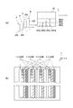
- FIG. 1A shows an example of the configuration of the main part of the modeling apparatus 10.
- FIG. 1B shows an example of a more detailed configuration of the discharge unit 12. It is a figure which shows an example of the operation
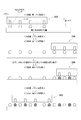
- FIG. 2A shows an example of an operation for forming an ink layer constituting the three-dimensional object 50.
- FIG. 2B shows an example of how ink tods are formed in each main scanning operation for the same region. It is a figure explaining the scanning to the lamination direction performed in the modeling apparatus of the conventional structure.
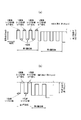
- FIG. 3A shows an example of scanning in the stacking direction.
- FIG. 3B shows another example of scanning in the stacking direction.
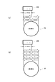
- FIG. 4A shows a simplified state when the n + 1th ink layer (n + 1th layer) is flattened.
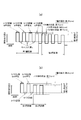
- FIG. 4B is a diagram for explaining the influence of various variations. It is a figure explaining the scanning to the lamination direction performed in the modeling apparatus 10 of this example.
- FIG. 5A shows an example of scanning in the stacking direction.
- FIG. 5B shows another example of scanning in the stacking direction. It is a figure which shows an example of the operation
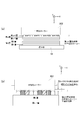
- FIG. 7A shows an example of the state of ink dots when an ink layer is formed by a conventional method.
- FIG. 7B shows an example of the state of ink dots when an ink layer is formed with the configuration of this example.
- An example of a more specific configuration of the flattening roller unit 222 is shown.
- FIG. 8A shows an example of the configuration of the flattening roller unit 222.
- FIG. 8B shows another example of the configuration of the flattening roller unit 222.
- FIG. 8C shows still another example of the configuration of the flattening roller unit 222. It is a figure explaining the modification of a structure and operation
- FIG. 9A shows an example of the operation in the case of performing the flattening during the main scanning operation in one direction and the other direction.
- FIG. 9B shows an example of the configuration of the discharge unit 12 used in this case. It is a figure explaining the various systems which perform operation
- Fig.10 (a) shows an example of a structure of the inkjet head 200 used for modeling.
- FIG. 10B shows an example of the operation of forming the ink layer by the multi-pass method of the large pitch pass method. It is a figure explaining the various systems which perform operation
- FIG. 10 (a) shows an example of a structure of the inkjet head 200 used for modeling.
- FIG. 10B shows an example of the operation of forming the ink layer by the multi-pass method of the large pitch
- FIG. 11A shows an example of an operation for forming an ink layer by the multi-pass method of the small pitch pass method.
- FIG. 11B shows an example of the operation of forming the ink layer by the multi-pass method of the full-surface sequential pass method. It is a figure explaining the further modification of a structure and operation
- FIG. 12A shows an example of the configuration of the inkjet head 200 and the configuration of the three-dimensional object 50 to be modeled.
- FIG. 12B shows the direction of movement of the inkjet head 200 in the sub-scanning operation performed after each main scanning operation when the ink layer is formed by the large pitch pass method. It is a figure explaining the further modification of a structure and operation
- FIG. 13A and 13B show ink jets in the sub-scanning operation performed after each main scanning operation in the case where the ink layer is formed by each of the large pitch pass method, the small pitch pass method, and the entire sequential pass method.
- the direction of movement of the head 200 is shown. It is a figure explaining in more detail operation
- FIG. 14A is a diagram illustrating an example of the configuration of the inkjet head 200.
- FIG. 14B shows an example of the state of the ink dots formed in the main scanning operation and the sub-scanning operation (X scanning) performed between the main scanning operations in the small pitch pass system operation. It is a figure explaining in more detail operation
- FIG. 1 shows an example of a modeling apparatus 10 according to an embodiment of the present invention.
- FIG. 1A shows an example of the configuration of the main part of the modeling apparatus 10.
- the modeling apparatus 10 is an apparatus (three-dimensional object modeling apparatus) that models the three-dimensional object 50 by the layered modeling method.
- the additive manufacturing method is, for example, a method of forming the three-dimensional object 50 by stacking a plurality of layers.
- the three-dimensional object 50 is, for example, a three-dimensional structure.
- the modeling apparatus 10 may have the same or similar configuration as a known modeling apparatus.
- the modeling apparatus 10 may be an apparatus in which a part of the configuration of a known inkjet printer is changed, for example.
- the modeling apparatus 10 may be an apparatus in which a part of an inkjet printer for two-dimensional image printing using ultraviolet curable ink (UV ink) is changed.
- the modeling apparatus 10 may further include various configurations necessary for modeling or coloring the three-dimensional object 50, for example.
- the modeling apparatus 10 includes a discharge unit 12, a main scanning driving unit 14, a modeling table 16, a sub-scanning driving unit 18, a stacking direction driving unit 20, and a control unit 22.
- the ejection unit 12 is a part that ejects droplets (ink droplets) that are the material of the three-dimensional object 50.
- the ejection unit 12 ejects ink droplets of ink that is cured according to predetermined conditions, and the ink ejected from the ejection unit 12 is discharged. By curing, an ink layer is formed, and the three-dimensional object 50 is formed by stacking a plurality of these layers.
- the ink for example, an ultraviolet curable ink that is cured by irradiation with ultraviolet rays is used.
- the ink is, for example, a liquid ejected from an inkjet head.
- the inkjet head is an ejection head that ejects droplets by an inkjet method, for example.
- the discharge unit 12 includes an ultraviolet light source. By irradiating the ultraviolet light from the ultraviolet light source toward the ink, the ink is cured to form an ink layer.
- the discharge unit 12 may form a support layer around the three-dimensional object 50.
- the support layer is, for example, a layered object that supports the three-dimensional object 50 by surrounding the outer periphery of the three-dimensional object 50 being modeled, and is dissolved and removed by, for example, water after the modeling of the three-dimensional object 50 is completed.
- the main scanning driving unit 14 is a driving unit that causes the ejection unit 12 to perform a main scanning operation (Y scanning).
- causing the ejection unit 12 to perform the main scanning operation means, for example, causing the inkjet head included in the ejection unit 12 to perform the main scanning operation.
- the main scanning operation is, for example, an operation of ejecting ink droplets while moving in a preset main scanning direction (Y direction in the drawing).
- the main scanning drive unit 14 is an example of a first direction scanning drive unit.
- the first direction scanning drive unit performs, for example, the inkjet head 200 in the first direction scanning that moves relative to the modeling table 16 in the first direction set in advance while discharging ink droplets. It is a drive part to be turned on.
- the main scanning drive unit 14 includes a carriage 102 and a guide rail 104.
- the carriage 102 is a holding unit that holds the discharge unit 12 so as to face the modeling table 16.
- holding the discharge unit 12 so as to face the modeling table 16 is, for example, holding the discharge unit 12 so that the discharge direction of the ink droplets is a direction toward the modeling table 16.
- the carriage 102 moves along the guide rail 104 while holding the discharge unit 12.
- the guide rail 104 is a rail-like member that guides the movement of the carriage 102 and moves the carriage 102 in accordance with an instruction from the control unit 22 during the main scanning operation.
- the movement of the discharge unit 12 in the main scanning operation may be a relative movement with respect to the three-dimensional object 50. Therefore, in the modification of the configuration of the modeling apparatus 10, for example, the position of the discharge unit 12 may be fixed, and the modeling table 16 may be moved, for example, to move the three-dimensional object 50 side.
- the modeling table 16 is a table-like member that supports the three-dimensional object 50 being modeled.
- the modeling table 16 is disposed at a position facing the inkjet head in the discharge unit 12, and the three-dimensional object 50 being modeled is placed on the upper surface of the modeling table 16.
- the modeling table 16 has a configuration in which at least the upper surface can move in the vertical direction (Z direction in the drawing), and is driven by the stacking direction driving unit 20 to form the three-dimensional object 50.
- the upper surface is moved in the vertical direction as it progresses.
- the distance between the head bases which is the distance between the inkjet head in the discharge unit 12 and the modeling table 16, is changed as appropriate, and the surface between the modeling surface in the three-dimensional object 50 during modeling and the discharge unit 12 is changed. Adjust the distance (gap).
- the inter-head base distance may be more specifically, for example, a distance between the nozzle surface in which the nozzle holes are formed in the ink jet head and the upper surface of the modeling base 16.
- the surface to be shaped of the three-dimensional object 50 is a surface on which the next ink layer is formed by the ink ejected from the ejection unit 12, for example.
- the sub-scanning drive unit 18 is a drive unit that causes the ejection unit 12 to perform a sub-scanning operation (X scanning).
- causing the ejection unit 12 to perform the sub-scanning operation means, for example, causing the inkjet head included in the ejection unit 12 to perform the sub-scanning operation.
- the sub-scanning operation is, for example, an operation that moves relative to the modeling table 16 in the sub-scanning direction (X direction in the drawing) orthogonal to the main scanning direction.
- the sub-scanning drive unit 18 is an example of a second direction scanning drive unit.
- the second direction scanning drive unit is, for example, a drive unit that moves the inkjet head relative to the modeling table 16 in a second direction orthogonal to the first direction.
- the sub-scanning drive unit 18 causes the inkjet head to perform a sub-scanning operation by, for example, fixing the position of the ejection unit 12 in the sub-scanning direction and moving the modeling table 16.
- the sub-scanning drive unit 18 may cause the inkjet head to perform a sub-scanning operation by moving the ejection unit 12 while fixing the position of the modeling table 16 in the sub-scanning direction.
- the stacking direction driving unit 20 is a driving unit that moves at least one of the ejection unit 12 or the modeling table 16 in a stacking direction (Z direction in the drawing) orthogonal to the main scanning direction and the sub-scanning direction.
- the lamination direction is, for example, a direction in which a plurality of layers are laminated in the additive manufacturing method.
- moving the discharge unit 12 in the stacking direction means, for example, moving the ink jet head in the discharge unit 12 in the stacking direction.
- Moving the modeling table 16 in the stacking direction means, for example, moving the position of at least the upper surface of the modeling table 16.
- the stacking direction driving unit 20 moves the at least one of the ejection unit 12 or the modeling table 16 in the stacking direction, thereby causing the inkjet head to perform scanning in the Z direction (Z scanning) and changing the distance between the head units.
- the stacking direction driving unit 20 moves the modeling table 16 while fixing the position of the discharge unit 12 in the stacking direction, for example. Further, the stacking direction driving unit 20 may move the discharge unit 12 while fixing the position of the modeling table 16 in the stacking direction.
- the control unit 22 is, for example, a CPU (Central Processing Unit) of the modeling apparatus 10, and controls the modeling operation of the three-dimensional object 50 by controlling each unit of the modeling apparatus 10. It is preferable that the control part 22 controls each part of the modeling apparatus 10 based on the shape information, the color image information, etc. of the solid object 50 which should be modeled, for example. A more specific operation for modeling the three-dimensional object 50 will be described in more detail later.
- a CPU Central Processing Unit
- FIG. 1B shows an example of a more detailed configuration of the discharge unit 12.
- the discharge unit 12 includes a plurality of colored ink heads 202y, 202m, 202c, 202k (hereinafter referred to as colored ink heads 202y-k), a modeling material head 204, a white ink head 206, a clear ink It has an ink head 208, a support material head 210, a plurality of ultraviolet light sources 220, and a flattening roller unit 222.
- the colored ink heads 202y to 202k, the modeling material head 204, the white ink head 206, the clear ink head 208, and the support material head 210 are ink jet heads that eject ink droplets by an ink jet method.
- the colored ink heads 202y to 202k, the modeling material head 204, the white ink head 206, the clear ink head 208, and the support material head 210 for example, receive ink droplets of ultraviolet curable ink.
- the modeling material head 204 As the colored ink heads 202y to 202k, the modeling material head 204, the white ink head 206, the clear ink head 208, and the support material head 210, for example, known ink jet heads can be suitably used.
- these inkjet heads have a nozzle row in which a plurality of nozzle holes are arranged in the sub-scanning direction on the surface facing the modeling table 16.
- each inkjet head ejects ink droplets in the direction from the nozzle hole toward the modeling table 16.
- the direction of the nozzle row in which the plurality of nozzle holes are arranged is a direction orthogonal to the main scanning direction.
- the arrangement of the colored ink heads 202y to 202k, the modeling material head 204, the white ink head 206, the clear ink head 208, and the support material head 210 is not limited to the illustrated configuration, and various changes may be made. May be.
- some of the inkjet heads may be arranged so that the positions in the sub-scanning direction are shifted from other inkjet heads.
- the discharge unit 12 may further include, for example, an ink jet head for each color, R (Red: G), G (Green), B (Blue), orange, or the like.
- the colored ink heads 202y to 202k are ink jet heads that discharge ink droplets of colored inks of different colors.
- the colored ink heads 202y-k are ink droplets of ultraviolet curable inks of Y (Yellow: yellow), M (Magenta: magenta), C (Cyan: cyan), and K (Black: black). Is discharged.
- the modeling material head 204 is an inkjet head that ejects ink droplets of ink used for modeling inside the three-dimensional object 50.
- the modeling material head 204 ejects ink droplets of modeling ink (model material MO) of a predetermined color.
- the modeling ink may be, for example, an ink dedicated to modeling.
- the modeling ink is an ink having a color different from each color of the CMYK ink. For example, white ink or clear ink may be used as the modeling ink.
- the white ink head 206 is an inkjet head that ejects ink droplets of white (W) ink.
- the clear ink head 208 is an ink jet head that discharges ink droplets of clear ink.
- the clear ink is a clear color ink that is a transparent color (T).
- the support material head 210 is an ink jet head that ejects ink droplets containing the material of the support layer.
- a water-soluble material that can be dissolved in water after the three-dimensional object 50 is formed as the material for the support layer.
- the material since the material is removed after modeling, it is preferable to use a material that has a lower degree of curing with ultraviolet light than the material constituting the three-dimensional object 50 and is easily decomposed.
- the well-known material for support layers can be used suitably, for example.
- the plurality of ultraviolet light sources 220 are an example of an ultraviolet irradiation unit, and generate ultraviolet rays that cure the ultraviolet curable ink.
- the ultraviolet light source 220 for example, UVLED (Ultra Violet Light Emitting Diode: (ultraviolet LED)) or the like can be suitably used. It is also conceivable to use a metal halide lamp, a mercury lamp, or the like as the ultraviolet light source 220.
- each of the plurality of ultraviolet light sources 220 includes a colored ink head 202y-k, a modeling material head 204, a white ink head 206, a clear ink head 208, and a support material head 210.
- the discharge unit 12 is disposed on one end side and the other end side in the main scanning direction so as to be sandwiched. More specifically, for example, one ultraviolet light source 220 is disposed on one end side of the discharge unit 12 as indicated by reference numeral UV1 in the drawing. In addition, one ultraviolet light source 220 indicated by reference numeral UV2 in the drawing is also disposed on the other end side of the discharge unit 12.
- the flattening roller unit 222 has a configuration for flattening the ultraviolet curable ink layer formed during the modeling of the three-dimensional object 50.
- the flattening roller unit 222 includes the colored ink heads 202y to 202k, the modeling material head 204, the white ink head 206, the clear ink head 208, and the support material head 210, and the other side. It arrange
- the flattening roller unit 222 includes a flattening roller 302, a blade 304, and an ink collection unit 306.
- the flattening roller 302 is an example of a flattening unit that flattens the ink layer formed by the inkjet head.
- the outer peripheral surface of the flattening roller 302 is in contact with the surface of the ink layer during the main scanning operation.
- the ink layer is flattened.
- the blade 304 is a blade member that peels off the ink scraped off by the flattening roller 302 from the flattening roller 302.
- the ink collection unit 306 is a collection unit that collects the ink that the blade 304 has peeled off from the flattening roller 302.
- the discharge unit 12 performs an operation of modeling the three-dimensional object 50 in accordance with an instruction from the control unit 22. Further, the ink layer is flattened by the flattening roller unit 222 during the modeling operation. The operation of flattening the ink layer and the more specific configuration of the flattening roller unit 222 will be described in more detail later.
- FIG. 2 shows an example of an operation for modeling the three-dimensional object 50 in this example.
- the modeling apparatus 10 performs modeling of the three-dimensional object 50 by a multi-pass method, for example.
- modeling with the multi-pass method means, for example, forming each ink layer constituting the three-dimensional object 50 by the multi-pass method.
- forming each ink layer by the multi-pass method means that, for example, in the operation of forming one ink layer, the ink jet head is scanned a plurality of times with respect to the same position of the three-dimensional object 50 being modeled. It is to perform the operation.
- the inkjet head when the inkjet head performs a plurality of main scanning operations on the same position of the three-dimensional object 50 during modeling, for example, the inkjet head performs a plurality of main scanning operations with the sub-scanning operation interposed therebetween. Is to do it.
- the method of forming the ink layer by the multipass method is more specifically, for example, the same as or similar to the case of printing by the multipass method in a printing apparatus (2D printer) that prints a two-dimensional image. It is possible to do it. Moreover, when modeling a three-dimensional object with the modeling apparatus 10, it is possible to use various other methods as a specific method of forming an ink layer by a multi-pass method.
- a multi-pass operation is performed by a method (large pitch pass method) in which the feed amount in the sub-scan operation is set to a predetermined pass width.
- the feed amount in the sub-scanning operation is a relative movement amount of the inkjet head (colored ink heads 202y to 202k, etc.) with respect to the modeling table 16 (see FIG. 1) in one sub-scanning operation.
- the operation of the multi-pass method other than the large pitch pass method will be described in detail later.
- FIG. 2A shows an example of an operation for forming an ink layer constituting the three-dimensional object 50.
- a plurality of inkjet heads (colored ink heads 202y to 202k, modeling material head 204, white ink head 206, clear ink head) in the discharge unit 12 (see FIG. 1). 208 and the support material head 210) are shown as the inkjet head 200.
- the other ink jet heads in the discharge unit 12 move relative to the modeling table 16 together with the ink jet head shown as the ink jet head 200, thereby performing a main scanning operation, a sub scanning operation, and the like. Do.
- the main scanning drive unit 14 performs a plurality of preset positions for each position of the ink layer.
- the inkjet head 200 is caused to perform the main scanning operation for the number of passes.
- the sub-scanning drive unit 18 moves the inkjet head 200 relative to the modeling table 16 by a predetermined pass width every time a predetermined number of main scanning operations are performed.
- the pass width is set to a width obtained by dividing the length of the nozzle row in the sub-scanning direction by the number of passes.
- the length of the nozzle row is, for example, the length of the nozzle row in the inkjet head 200 that performs the sub-scanning operation.
- FIG 2A shows an example of the operation of the inkjet head 200 in the case where the number of passes is four and the ink layer is formed by the large pitch pass method.
- the main scanning operation in one direction (right side in the drawing) in the main scanning direction is performed, and the sub scanning operation is performed every time the main scanning operation is performed. An illustration was made.
- the ink jet head 200 is moved in the main scanning direction in the opposite direction to that in the main scanning operation, and the ink jet head 200 is moved to the original direction. Return to the position.
- the position of the inkjet head 200 in the sub-scanning direction is moved to the position indicated by the symbol A, and then the main scanning operation is performed on the range indicated by the arrow 402a in the three-dimensional object 50. Then, the first main scanning operation is performed on the region 404a in the drawing.
- the main scanning operation is performed on the range indicated by the arrow 402b in the three-dimensional object 50.
- a second main scanning operation for the region 404a and a first main scanning operation for the region 404b are performed.
- the main scanning operation is performed on the range indicated by the arrow 402c in the three-dimensional object 50.
- a third main scanning operation for the region 404a, a second main scanning operation for the region 404b, and a first main scanning operation for the region 404c are performed.
- the main scanning operation is performed on the range indicated by the arrow 402d in the three-dimensional object 50.
- a fourth main scanning operation for the region 404a, a third main scanning operation for the region 404b, a second main scanning operation for the region 404c, and a first main scanning operation for the region 404d are performed.
- modeling of solid thing 50 by a multipass method can be performed appropriately, for example.
- the three-dimensional object 50 can be appropriately shaped by driving the inkjet head 200 by the serial method. it can.
- the pass width is not limited to the same as the width obtained by dividing the length of the nozzle row by the number of passes, but is substantially the same as the width obtained by dividing the length of the nozzle row by the number of passes. It may be of equal width. In this case, “substantially equal width” means that, for example, the pass width and the nozzle row are excluded except for adjustments set according to operational convenience, various design intentions, and allowable error amounts.
- the length is equal to the width divided by the number of passes.
- FIG. 2B is a diagram showing an example of how the ink tods are arranged in each main scanning operation for one region (for example, the region 404a).
- ink in the sub-scanning direction is shown in each main scanning operation.
- An example of how ink tods are arranged in the case where the droplet landing position is shifted within a range less than the nozzle pitch will be described.
- a line indicated as 1-pass printing indicates ink dots formed in the main scanning direction and arranged in the main scanning direction.
- a line indicated as two-pass printing indicates ink dots formed side by side in the main scanning direction in the second main scanning operation.
- a line indicated as three-pass printing indicates ink dots formed side by side in the main scanning direction in the third main scanning operation.
- a line indicated as four-pass printing indicates ink dots formed side by side in the main scanning direction in the fourth main scanning operation.
- the modeling resolution in the sub-scanning direction can be set to a high resolution corresponding to a distance smaller than the interval (nozzle pitch) between nozzle holes in one nozzle row. Moreover, thereby, modeling with high resolution can be performed appropriately.
- the modeling apparatus 10 performs scanning in the stacking direction (Z direction) of the ink layers in addition to the main scanning operation and the sub scanning operation. More specifically, as the scanning in the stacking direction, the position of the upper surface of the modeling table 16 is changed by the stacking direction driving unit 20 (see FIG. 1) in accordance with the progress of the modeling of the three-dimensional object 50. Therefore, scanning in the stacking direction performed in this example will be described in more detail below. For convenience of explanation, first, scanning in the stacking direction performed in a modeling apparatus having a conventional configuration will be described.
- FIG. 3 is a diagram for explaining scanning in the stacking direction, which has been performed in a modeling apparatus having a conventional configuration.
- FIG. 3A shows an example of scanning in the stacking direction.
- the main scanning operation is performed only in one direction in the main scanning direction, as in the case described with reference to FIG. More specifically, of the reciprocation of the inkjet head 200 in the main scanning direction, ink droplets are ejected only in the return path (Y return path) to perform the main scanning operation. Further, in the forward path (Y forward path), only movement is performed without ejecting ink droplets.
- the ink layer is flattened during the main scanning operation by the flattening roller unit 222 (see FIG. 1) in the discharge unit 12. More specifically, in the case shown in FIG. 3A, the flattening by the flattening roller unit 222 is performed simultaneously with the main scanning operation (1 pass printing to 4 pass printing) of each time.
- movement is set to the same height.
- the height of the modeling table 16 is the position of the modeling table 16 relative to the inkjet head 200 in the stacking direction. Therefore, in this case, the main scanning operation and the flattening of the ink layer are performed with the same distance between the inkjet head 200 and the modeling table 16.
- the distance between the inkjet head 200 and the modeling table 16 is wide (relief when returning).
- the inkjet head 200 is moved. If comprised in this way, the unnecessary contact etc. between the inkjet head 200 and the solid object 50 during modeling can be avoided appropriately.
- the number of passes is four, an ink layer having a thickness of about 30 ⁇ m is formed by four main scanning operations, and the surface is flattened. Further, in this case, when the thickness of one ink layer after flattening is about 25 ⁇ m, the above contact and the like can be avoided if the return escape distance is about 150 ⁇ m, for example.
- the thickness of the ink layer after the flattening is equal to Only the modeling table 16 is lowered, and the distance between the inkjet head 200 and the modeling table 16 is increased. Thereafter, the next ink layer is formed (for example, the operation shown as second layer recording in the drawing is performed).
- the direction of the main scanning operation may be performed in two directions (both directions), that is, the forward path and the backward path.
- scanning in the stacking direction may be performed in accordance with the direction in which the main scanning operation is performed.
- FIG. 3B is a diagram illustrating another example of scanning in the stacking direction, and illustrates an example of scanning in the stacking direction when performing main scanning operation in two directions (both directions).
- the modeling time can be shortened as compared with the case where the main scanning operation is performed only on one of the forward path and the backward path.
- the flattening operation is performed only in one of the forward path and the backward path in the main scanning direction.
- the flattening roller unit is provided only on one side in the main scanning direction as in the configuration of the discharge unit 12 described with reference to FIG. It is preferable to perform planarization only when performing a scanning operation.
- the main scanning operation and the flattening are performed only during the main scanning operation in the return path during the reciprocation in the main scanning direction. In the forward main scanning operation, flattening is not performed, and only the main scanning operation is performed.
- the distance between the ink jet head 200 and the modeling table 16 is the same as or similar to the time of the main scanning operation in the backward path in the case of the description in FIG. In the same state, the main scanning operation and the flattening of the ink layer are performed. Further, during the main scanning operation in the forward path, a state where the distance between the ink jet head 200 and the modeling table 16 is widened (a state of escape during the forward path), as in the forward path described with reference to FIG. ) To perform the main scanning operation.
- FIG. 4 is a diagram for explaining a problem caused by the flattening operation.
- FIG. 4A is a diagram schematically showing a state when the n + 1th ink layer (n + 1th layer) is flattened.
- the (n + 1) th layer is the n + 1th ink layer (n is an integer of 1 or more) from the bottom among the ink layers stacked on the modeling table 16, and the nth ink layer from the bottom. It is formed on the (nth layer) by the multipass method.
- the ink layer is formed by the multi-pass method, among the plurality of main scanning operations performed on the same position of the three-dimensional object 50 being modeled, at the time of the subsequent main scanning operation, The main scanning operation and the flattening are performed on the region where the ink dots are formed in the main scanning operation.
- the already formed ink dots are usually already cured by ultraviolet irradiation or the like.
- the height of the modeling table 16 during the main scanning operation for performing the planarization when forming the (n + 1) th layer. are the same height. Therefore, in this case, the flattening roller 302 (see FIG. 1) in the flattening roller unit 222 that performs flattening easily comes into contact with the ink surface constituted by the dots of the already cured ink.
- the flattening roller 302 that moves in the main scanning direction may jump, causing extra vibration or the like (chatter).
- extra unevenness or the like for example, chatter marks
- chatter marks may occur on the surface of the ink after flattening, which may affect the flattening result.
- precise lamination is not performed, and unevenness or the like may occur on the surface of the three-dimensional object 50 to be formed. As a result, the quality of the three-dimensional object 50 may be deteriorated.
- FIG. 4B is a diagram for explaining the influence of various variations.
- the ink jet method When ink droplets are ejected by the ink jet method, it is inevitable that some variation occurs in the ink droplet ejection position, the landing position, and the like due to the principle of the ink jet head. Further, in this case, due to the influence of the variation in these positions, there is a case where a difference occurs in the overlapping manner of adjacent ink dots, and the thickness (height) of the ink layer may vary. More specifically, for example, when the ink layer is formed so that the thickness of one layer is about 25 ⁇ m, the thickness of the ink layer may vary by about 5 ⁇ m due to such factors. .
- the thickness (height) of the ink layer flattened by the flattening roller 302 may vary by about 5 ⁇ m.
- the height of the ink dot after flattening may vary by about 20% of the thickness of the ink layer.
- the height of the ink dots after flattening is, for example, the actual height of the individual ink dots that form the ink layer.
- the ink layer thickness is, for example, a design value set in advance as the thickness of one ink layer.
- the position of the lower end of the flattening roller 302 is lower than the vertex position of the cured ink dot and comes into contact with the cured ink dot.
- the state that is, the state of rubbing the ink surface cured by the flattening roller 302 is likely to occur.
- the hardened dots are scraped off, and extra debris (for example, shaving-like debris, etc.) is generated.
- the flattening operation may be hindered. More specifically, for example, in the case of performing flattening with the configuration of the flattening roller unit 222 of this example, when the flattening roller 302 scrapes off ink containing excess residue, for example, the blade 304 (FIG. 1). (Ref.) There is a possibility that debris accumulates on the upper surface and the operation of the flattening roller unit 222 is hindered.
- the inventor of the present application has found a configuration capable of appropriately suppressing the occurrence of such debris through intensive research. Moreover, the structure of the modeling apparatus 10 of this example was considered as such a specific structure. Therefore, hereinafter, the operation of the modeling apparatus 10 of this example will be described in more detail.
- FIG. 5 is a diagram illustrating scanning in the stacking direction performed in the modeling apparatus 10 of this example. Except as described below, the scanning in the stacking direction performed in this example is the same as or similar to the operation in the conventional configuration described using, for example, FIG.
- FIG. 5A shows an example of scanning in the stacking direction.
- the main scanning operation is performed only in one direction in the main scanning direction as in the case described with reference to FIG. More specifically, in this case, of the reciprocation of the inkjet head 200 in the main scanning direction, ink droplets are ejected only in the return path, and the main scanning operation is performed. In the forward path, only movement is performed without ejecting ink droplets.
- flattening is performed by the flattening roller unit 222 (see FIG. 1).
- the main scanning driving unit 14 moves the inkjet head 200 in at least one direction in the main scanning direction.
- the main scanning operation of moving the inkjet head 200 in one direction is performed a plurality of times for the same position of the three-dimensional object being modeled.
- the flattening roller 302 in the flattening roller unit 222 moves together with the inkjet head 200 in the main scanning operation in this one direction, and flattens the ink layer.
- the stacking direction driving unit 20 lowers the modeling table 16 by the thickness of the one ink layer.
- the stacking direction driving unit 20 has a distance between the head bases that is the distance between the inkjet head 200 and the modeling base 16 in the ejection unit 12 as compared with that before the start of the formation of the one ink layer. Increase by the thickness of the ink layer.
- the setting of the height of the modeling table 16 during the main scanning operation is different from the case described with reference to FIG. More specifically, in this case, in the operation of forming one ink layer, the height of the modeling table 16 at the time of the main scanning operation is not made the same, and the main scanning operation is performed a predetermined number of times. An operation of lowering the modeling table 16 a little (operation between steps between paths) is performed. In addition, as a result, in each of a plurality of main scanning operations in one direction performed in the operation of forming one ink layer, the distance between the head units in the main scanning operation to be performed later is performed first. The distance is larger than the distance between the heads during the scanning operation. In other words, in this example, the distance between the heads is increased stepwise while the main scanning operation is performed a plurality of times to form one ink layer.
- the stacking direction driving unit 20 determines the distance between the heads from the thickness of the one ink layer. Are preferably different from each other by a small distance. More specifically, in the case shown in FIG. 5A, the stacking direction drive unit 20 sets the distance between the head units to 2 ⁇ m in the next main scanning operation every time the main scanning operation is performed. Set only larger. If comprised in this way, the distance between head stands can be changed in steps. Thereby, for example, the head-to-head distance can be changed more appropriately within a range where flattening is possible.
- the main scanning operation for flattening can be considered as a configuration in which the position of the modeling table 16 is changed at least during the continuous main scanning operation.
- the inkjet is performed in the same manner as described with reference to FIG.
- the inkjet head 200 is moved in a state where the distance between the head 200 and the modeling table 16 is wide (a state of escape when returning). In this case, it is conceivable that the distance of return escape is about 150 ⁇ m, for example.
- the modeling table 16 is lowered by the thickness of the one ink layer (for example, 25 ⁇ m), and the distance between the head units is adjusted in accordance with the operation of forming the next ink layer. Adjust the distance. Further, in this case, lowering the modeling table 16 by the thickness of one ink layer means, for example, when performing the first main scanning operation (one-pass recording) performed when forming each layer as shown in the figure. For the height of the modeling table 16, the distance between the head units is changed by the thickness of one ink layer.
- the distance between the head units during the main scanning operation for forming one ink layer can be increased stepwise, for example, every time the main scanning operation is performed. Therefore, according to this example, for example, in the flattening operation, it is possible to appropriately prevent the ink dots formed during the previous main scanning operation from coming into contact with the flattening roller 302. In addition, thereby, for example, it is possible to prevent generation of excess residue and perform more appropriate planarization.
- the amount of change in the head-to-table distance that is changed each time the main scanning operation is performed is not limited to 2 ⁇ m, and is preferably set as appropriate according to the required accuracy, the configuration of the apparatus, and the like.
- change_quantity it is preferable to set according to the kind etc. of the ink used in order to form the layer of the ink of 1 layer, and a layer simultaneously within 1 layer, for example.
- the amount of change in the head-to-table distance that is changed each time the main scanning operation is performed is, for example, The thickness is preferably about 0.5 to 5 ⁇ m.
- the operation for increasing the distance between the head units does not necessarily have to be performed every time the main scanning operation is performed.
- the distance between the head units at the time of the main scanning operation to be performed later is larger than the distance between the head units performed first for at least some of the main scanning operations. It is possible to do. More specifically, for example, when the number of passes is four as in the case described with reference to FIG. 5A, after the second main scanning operation (two-pass printing) is performed. Only the distance between the heads may be changed.
- the head-to-head distance is the same during the first and second main scanning operations.
- the distance between the heads is made the same.
- the distance between the heads is preferably set to about 5 ⁇ m, for example.
- the direction of the main scanning operation may be performed not only in one direction of the main scanning direction but also in the two directions (both directions) of the forward path and the backward path.
- scanning in the stacking direction may be performed in accordance with the direction in which the main scanning operation is performed.
- FIG. 5B is a diagram illustrating another example of scanning in the stacking direction, and illustrates an example of scanning in the stacking direction when performing a main scanning operation in two directions (both directions). Except as described below, the scanning in the stacking direction shown in FIG. 5B has been described with reference to the scanning in the stacking direction shown in FIG. 5A and FIG. The operation is the same as or similar to that in the conventional configuration.
- the setting of the height of the modeling table 16 during the main scanning operation is different from the case described with reference to FIG. More specifically, in this case, in the operation of forming one ink layer, a plurality of main scanning operations in one direction (for example, main scanning operation corresponding to 1-pass printing and 3-pass printing in the drawing). For each, the height of the modeling table 16 is not made the same, and the modeling table 16 is slightly lowered every time the main scanning operation is performed.
- the plurality of main scanning operations in one direction are, for example, main scanning operations in which flattening is performed by the flattening roller 302 of the flattening roller unit 222.
- the modeling table 16 is moved by the amount of escape at the time of return.
- the main scanning operation may be performed at the same height in the lowered state.
- the three-dimensional object can be formed in a shorter time by performing the main scanning operation in two directions (both directions).
- the distance between the head units during the main scanning operation in one direction for forming one ink layer can be increased stepwise, for example, every time the main scanning operation is performed. it can. Therefore, with this configuration, for example, in the flattening operation, it is possible to appropriately prevent the ink dots formed during the previous main scanning operation from coming into contact with the flattening roller 302. This also makes it possible to appropriately and sufficiently flatten the ink layer.
- flattening is not performed during the main scanning operation in the other direction, and the configuration and control of the modeling apparatus 10 can be appropriately simplified, for example, by setting the head table distance to the same distance. .
- FIG. 6 is a diagram illustrating an example of an operation for forming one ink layer. More specifically, the plurality of main scanning operations and planarization operations described with reference to FIG. Explain.
- FIG. 6A shows an example of a state during the first main scanning operation (one-pass printing).
- the height of the modeling table 16 is adjusted to the height at which the (n + 1) th layer is to be formed, and the ink is formed on the already formed nth layer. Form dots. Further, before the formed ink dots are cured, the surface is flattened by the flattening roller 302. Further, after the planarization, ultraviolet rays are irradiated to cure the ink dots.
- FIG. 6B shows an example of a state during the second main scanning operation (two-pass printing).
- ink dots are further formed on the n-th layer that has already been formed, in the vicinity of the ink dots that have been cured after planarization in the first main scanning operation. Further, before the formed ink dots are cured, the surface is flattened by the flattening roller 302. Further, after the planarization, ultraviolet rays are irradiated to cure the ink dots.
- FIG. 6C shows an example of a state during the third main scanning operation (3-pass printing).
- the third main scanning operation further ink dots are placed on the already formed n-th layer in the vicinity of the ink dots that have been hardened after planarization in the first and second main scanning operations. Form. Further, before the formed ink dots are cured, the surface is flattened by the flattening roller 302. Further, after the planarization, ultraviolet rays are irradiated to cure the ink dots.
- FIG. 6D shows an example of a state during the fourth main scanning operation (four-pass printing).
- the fourth main scanning operation further ink dots are formed on the already formed n-th layer in the vicinity of the ink dots cured after flattening by the first to third main scanning operations. To do. Further, before the formed ink dots are cured, the surface is flattened by the flattening roller 302. Further, after the planarization, ultraviolet rays are irradiated to cure the ink dots.
- the ink dots formed during the previous main scanning operation come into contact with the flattening roller 302. Can be prevented appropriately.
- the adhesion of debris to each part of the flattening roller unit 222 can be appropriately prevented by preventing the debris from being generated. More specifically, for example, in the case of the configuration in which the ink scraped up by the flattening roller 302 is removed by the blade 304 as in this example, the adhesion of debris to the flattening roller 302, the blade 304, or the like is more appropriately prevented. be able to. Accordingly, for example, the ink processing can be stabilized without deteriorating the flow of excess ink collected by the flattening roller unit 222. In addition, ink clogging and the like in the ink collection path can be prevented appropriately.
- the multi-pass can be performed while appropriately performing flattening by increasing the distance between the heads each time the main scanning operation is performed.
- Modeling by the method can be performed appropriately. Thereby, for example, a solid thing can be modeled more appropriately with high accuracy.
- the surface of the three-dimensional object to be formed can be smoothed by changing the distance between the heads little by little for each main scanning operation. More specifically, for example, even when the surface of a three-dimensional object has a gentle slope shape, it is possible to prevent the formation of a conspicuous stepped contour or the like, and to more appropriately perform modeling with a smooth surface.
- the ink layer is formed by the configuration of this example, it is considered that the ink dots constituting the ink layer are in a different state from the case of forming by the conventional method. Therefore, this point will also be briefly described.
- FIG. 7 is a diagram for explaining the state of the ink dots formed in this example.
- the ink dots formed by each main scanning operation are the same as the ink dots formed by each main scanning operation in FIG. Shown with the same shading pattern.
- FIG. 7A shows an example of the state of ink dots when an ink layer is formed by a conventional method.
- the case where the ink layer is formed by the conventional method is, for example, the case where the ink layer is formed without performing the operation of lowering the modeling table 16 every time the main scanning operation is performed.
- the height of the modeling table 16 during the main scanning operation for flattening is constant. Therefore, in this case, the ink dots formed in each main scanning operation are flattened at the same height. As a result, there is no difference in the height of the ink dot after curing depending on which main scanning operation is performed.
- FIG. 7B shows an example of the state of ink dots when an ink layer is formed with the configuration of this example. Further, in FIG. 7B, as an example of the state of dots when the ink layer is formed with the configuration of this example, the ink layer is formed by the method described with reference to FIGS. The example of the state of the dot at the time of forming is shown.
- the modeling table 16 is lowered every time the main scanning operation is performed, the height of the modeling table 16 during the main scanning operation for performing the flattening is different for each main scanning operation. Therefore, the ink dots formed in each main scanning operation are flattened at different heights. As a result, a difference occurs in the height of the dot of the ink after curing depending on which main scanning operation is performed as illustrated. Therefore, when the ink layer is formed by the configuration of this example, it is considered that the state of the ink dots is different from the case of forming by the conventional method.
- the manner of contact between the ink dots formed in each main scanning operation and the flattening roller 302 in the flattening roller unit 222 is considered to differ depending on the specific configuration of the apparatus. For example, when the number of passes is about 4 passes, only the ink dots formed by the two main scanning operations in the latter half of the four main scanning operations performed on the same position are flat depending on the configuration of the apparatus. The case where it contacts with the plasticizing roller 302 can be considered. In addition, it is also conceivable that only the ink dots formed in the last main scanning operation among the plurality of main scanning operations performed on the same position are in contact with the flattening roller 302. For this reason, the specific dot shape is not limited to the illustrated case and may vary depending on the specific configuration of the apparatus.
- the flattening roller unit 222 includes the flattening roller 302, the blade 304, and the ink collection unit 306.
- the flattening roller 302 is, for example, a roller that scrapes off the uncured ink, and removes a part of the uncured ink by contacting the surface of the ink layer during the main scanning operation. Then, the ink layer is flattened. Thereby, the flattening roller 302 flattens the surface of the ink during the operation of forming one ink layer. Further, in this case, the flattening of the ink layer may be, for example, removing ink in a portion exceeding a thickness set in advance as the thickness of one ink layer.
- FIG. 8 shows an example of a more specific configuration of the flattening roller unit 222.
- FIG. 8A shows an example of the configuration of the flattening roller unit 222.
- the left side is a cross-sectional view of the flattening roller unit 222.
- the right side is a perspective view of the flattening roller unit 222.
- FIG. 8A in the case where the nth ink layer is formed on the cured n ⁇ 1th layer, the state of flattening the uncured ink layer is simplified. Shown in the form.
- the flattening roller unit 222 further includes a suction unit 308 in addition to the flattening roller 302, the blade 304, and the ink collection unit 306.
- the suction unit 308 is configured to suck the ink removed by the flattening roller 302, and moves the ink collected by the ink collection unit 306 to the waste ink tank 312 by being sucked by the pump 310, for example. .
- the pump 310 releases, for example, air sucked from the waste ink tank 312. Accordingly, air is sucked through the waste ink tank 312 and the suction unit 308 (air suction), and the ink is moved to the waste ink tank 312 together with the air.
- the pump 310 and the waste ink tank 312 may be disposed outside the discharge unit 12 (see FIG. 1). According to this configuration, for example, it is possible to appropriately prevent the ink removed by the flattening roller 302 from being excessively accumulated in the flattening roller unit 222. In addition, this makes it possible to more appropriately perform planarization, for example, when modeling is performed continuously for a long time.
- FIG. 8B shows another example of the configuration of the flattening roller unit 222. Except as described below, in FIG. 8B, the configuration with the same reference numerals as in FIG. 8A is the same as or similar to the configuration in FIG. Also, FIG. 8 (b) shows a cross-sectional view and a perspective view as in FIG. 8 (a).
- the flattening roller unit 222 has more suction portions 308 than in the case shown in FIG.
- the suction unit 308 added to the configuration of FIG. 8A is configured so that, for example, before the ink scraped up by the flattening roller 302 reaches the ink recovery unit 306, the ink is discharged on the blade 304, for example. Suction. With this configuration, for example, it is possible to more appropriately prevent the ink removed by the flattening roller 302 from being excessively accumulated in the flattening roller unit 222.
- FIG. 8C shows still another example of the configuration of the flattening roller unit 222. Except as described below, in FIG. 8C, the configuration denoted by the same reference numeral as in FIG. 8A is the same as or similar to the configuration in FIG. Also, FIG. 8C shows a cross-sectional view and a perspective view similarly to FIG. 8A.
- the flattening roller unit 222 further includes a pressurized air discharge unit 314, compared to the case shown in FIG.
- the pressurized air ejection unit 314 is configured to blow pressurized air onto the ink scraped up by the flattening roller 302, and before the ink scraped up by the flattening roller 302 reaches the ink recovery unit 306, Air is blown onto the ink on the blade 304.
- the ink that has been peeled off from the flattening roller 302 by the blade 304 is blown so as to move to the ink collecting unit 306.
- the pump 310 sends the air sucked from the waste ink tank 312 to the pressurized air discharge unit 314.
- the pressurized air discharge part 314 sprays the pressurized air (pressurized air) on the ink.
- air is sucked through the waste ink tank 312 and the suction unit 308 (air suction), and the ink is moved to the waste ink tank 312 together with the air.
- main scanning operation in two directions is performed, and flattening is performed only during main scanning operation in one direction.
- the main scanning drive unit 14 in the modeling apparatus 10 causes the inkjet head 200 in the discharge unit 12 (see FIG. 1) to perform a main scanning operation in one direction in the main scanning direction.
- the main scanning operation in the other direction in the main scanning direction is performed.
- the flattening roller 302 in the flattening roller unit 222 flattens the ink layer only during the main scanning operation in one direction among the main scanning operations in one direction and the other direction.
- the stacking direction driving unit 20 see FIG.
- FIG. 9 is a diagram for explaining a modified example of the configuration and operation of the modeling apparatus 10.
- FIG. 9A shows an example of the operation in the case of performing the flattening during the main scanning operation in one direction and the other direction.
- FIG. 9B shows an example of the configuration of the discharge unit 12 used in this case. Except as described below, the operation shown in FIG. 9 is the same as or similar to the operation described with reference to FIGS.
- the modeling table 16 (see FIG. 1) is lowered each time the main scanning operation is performed, and the distance between the head units is increased stepwise, regardless of the direction in which the inkjet head 200 is moved during the main scanning operation.
- the modeling table 16 is lowered by 2 ⁇ m every time the main scanning operation is performed.
- the discharge unit 12 having the flattening roller unit 222 on one side and the other side in the main scanning direction is used, and the flattening that becomes the rear side during the main scanning operation is performed.
- the flattening is performed by the flattening roller 302 (see FIG. 1) of the roller unit 222. That is, in this case, the main scanning drive unit 14 (see FIG. 1) causes the inkjet head 200 to perform a main scanning operation in one direction in the main scanning direction and a main scanning operation in the other direction in the main scanning direction. .
- the discharge unit 12 in the modeling apparatus 10 serves as a flattening unit, the first flattening roller 302 for flattening the ink layer during the main scanning operation in one direction, and the main scanning in the other direction. And a second leveling roller 302 for leveling the ink layer during operation.
- the discharge unit 12 includes an ultraviolet light source 220 denoted by reference numeral UV1 and an inkjet head 200 (support material head 210 and the like) as compared with the discharge unit 12 illustrated in FIG.
- a flattening roller unit 222 is further provided between the two.
- the flattening roller 302 in each of the two flattening roller units 222 rotates in the opposite direction.
- the flattening roller 302 in the flattening roller unit 222 disposed on the right side in the drawing rotates in the clockwise direction in the drawing.
- the flattening roller 302 in the flattening roller unit 222 disposed on the left side in the drawing rotates in a counterclockwise direction in the drawing.
- the discharge unit 12 further includes a mechanism that enables only one of the flattening roller units 222 according to the direction of the main scanning operation.
- a mechanism for example, a configuration in which the flattening roller unit 222 is held so as to be movable in the Z direction and only the effective flattening roller unit 222 is selected and lowered is conceivable.
- the stacking direction driving unit 20 (see FIG. 1) is configured so that the head base during the main scanning operation to be performed later in each of the plurality of main scanning operations performed in the operation of forming one ink layer.
- the distance between the heads is made larger than the distance between the heads during the main scanning operation to be performed first. Accordingly, not only for the main scanning operation in one direction but also for the main scanning operation in the other direction, the distance between the head units is increased stepwise each time the main scanning operation is performed.
- the three-dimensional object can be formed in a shorter time by performing the main scanning operation in two directions (both directions). Further, in this case, by using a plurality of flattening rollers 302 in accordance with the direction of the main scanning operation, it is possible to appropriately perform flattening in any direction of the main scanning operation.
- the ink dots formed during the previous main scanning operation are appropriately prevented from coming into contact with the flattening roller 302. be able to.
- the large pitch pass method which is a method of setting the feed amount in the sub-scanning operation to a predetermined pass width
- the large pitch pass method it is also possible to use a system other than the large pitch path system as the multi-path system operation.
- FIG. 10 and FIG. 11 are diagrams for explaining various methods for performing the multi-pass method.
- the number of passes is set to 4 using an inkjet head 200 having a nozzle array resolution of 150 dpi (dots per inch).
- An example of the operation in the case of forming an ink layer with a resolution (density) of 600 dpi will be described.
- the configuration and operation of the modeling apparatus 10 are the same as or similar to those described with reference to FIGS.
- the head-to-head distance can be increased every time the main scanning operation is performed a preset number of times. preferable. In this case, for example, it is preferable to increase the distance between the heads by a predetermined distance every time the main scanning operation for flattening is performed once.
- Fig.10 (a) shows an example of a structure of the inkjet head 200 used for modeling.
- the inkjet head 200 has a nozzle row in which a plurality of nozzle holes are arranged in a nozzle row direction parallel to the sub-scanning direction.
- the plurality of nozzle holes are arranged at a constant interval (nozzle pitch P) of 1/150 inch ( ⁇ 0.169 mm). Therefore, the length Lh of the nozzle row is (total number of nozzles ⁇ 1) ⁇ 0.169 mm.
- FIG. 10B is a diagram illustrating an example of an operation for forming an ink layer by a multi-pass method of a large pitch pass method.
- the circled numbers shown beside each region obtained by dividing the nozzle row of the inkjet head 200 into four are numbers for distinguishing each region in the nozzle row.
- the diagram shown on the right side of the inkjet head 200 is a diagram showing an example of an operation that repeats the main scanning operation and the sub-scanning operation, and the N-th main scanning operation (first pass) to the N-th main scanning operation (first pass).
- NPass the relationship between each area
- region in a nozzle row is an area
- the description described on the upper side of the figure shows the operation performed at the time of each main scanning operation and before and after the main scanning operation. Further, the right side of the figure shows the relationship between the number of times of performing the main scanning operation and the length of the region where the formation of the ink layer is completed as the completed row length.
- FIG. 11A is a diagram illustrating an example of an operation for forming an ink layer by a multi-pass method of a small pitch pass method.
- the main scanning operation is not performed by forming a single ink layer with a constant feed amount of the sub-scanning operation as in the large pitch pass method, but sandwiching the sub-scanning operation with a smaller feed amount.
- this is an operation for forming one ink layer by repeating the operation for a predetermined number of passes and the subsequent sub-scanning operation with a predetermined feed amount corresponding to the length of the nozzle row.
- the feed amount is smaller than the nozzle pitch P and an integral multiple of P / n. An example is shown.
- the ink layer can be appropriately formed by the multi-pass method of the small pitch pass method. Moreover, a solid thing can be modeled appropriately by laminating and forming a plurality of layers. Further, in this case, as can be seen from the comparison of the completed row lengths, the ink layer can be formed with a smaller number of main scanning operations than in the case of modeling with the large pitch pass method. Thereby, for example, modeling time can be shortened.
- the sub-scanning drive unit 18 performs nozzle row alignment in the sub-scanning direction.
- the inkjet head 200 is moved in the sub-scanning direction relative to the modeling table 16 by a sub-scanning direction moving distance that is a distance smaller than the width (Lh / n) obtained by dividing the length by the number of passes. I can say that.
- the movement distance in the sub-scanning direction is an integer multiple of the nozzle pitch sub-scanning direction component, which is the distance in the sub-scanning direction between adjacent nozzle holes in the nozzle row, and a distance less than the nozzle pitch sub-scanning direction component. It can be said that it is the distance added.
- the integer multiple of the nozzle pitch second direction component is, for example, the product of the nozzle pitch sub-scanning direction component and an integer of 0 or more. If comprised in this way, about the resolution in a subscanning direction, the high resolution corresponding to a distance smaller than a nozzle pitch subscanning direction component can be implement
- FIG. 11A as an example of the operation of the small pitch pass method, a case where the width of the three-dimensional object to be modeled (length in the sub-scanning direction) is larger than the length (Lh) of the nozzle row. It is shown. Therefore, in this case, every time the main scanning operation is performed four times, the sub-scanning operation is performed with the distance equal to the length Lh of the nozzle row as the feed amount. In a more generalized case, for example, after performing a main scanning operation for the number of passes on a region corresponding to the length Lh of the nozzle row, the sub-scanning is performed by a distance corresponding to the length Lh of the nozzle row.
- the inkjet head 200 is moved relative to the modeling table 16 in the direction. Further, in this case, after the inkjet head 200 is moved, the main scanning operation for the number of passes is further performed. If comprised in this way, even when the size of a solid object is large, for example, modeling of a solid object can be performed appropriately.
- ink droplets are simultaneously ejected from the nozzle array over the entire width of the three-dimensional object without performing such a large distance sub-scanning operation. It is also possible. With this configuration, for example, multi-pass modeling can be performed appropriately in the same manner as when a line-type inkjet head is used. Thereby, for example, modeling of a solid thing can be performed in a shorter time.
- FIG. 11B is a diagram showing an example of the operation of forming the ink layer by the multi-pass method of the full-surface sequential pass method.
- the full-surface sequential pass method is a method in which, for example, the same main scanning operation is sequentially performed on the entire surface of the ink layer.
- the same main scanning operation means, for example, in the operation of forming one ink layer, the same main scanning operation among the main scanning performed a plurality of times for the same position of the three-dimensional object being modeled. This is a scanning operation.
- the ink layer can be appropriately formed by the multi-pass method of the whole surface sequential pass method. Moreover, a solid thing can be modeled appropriately by laminating and forming a plurality of layers. Further, in this case, as can be seen from the comparison of the completed row lengths, for example, the ink layer can be formed with a smaller number of main scanning operations than in the case of modeling with the large pitch pass method. Thereby, for example, modeling time can be shortened.
- the sub-scanning drive unit 18 performs sub-scanning driving unit 18 every time a main scanning operation is performed. It can be said that this is an operation of moving the inkjet head 200 in the sub-scanning direction relative to the modeling table 16 by a distance corresponding to the length of the nozzle row in the scanning direction.
- the ink jet head 200 is subjected to the second main scanning operation for each position of the ink layer. A scanning operation is performed.
- the distance for moving the inkjet head 200 in the sub-scanning direction in the sub-scanning operation is, for example, a distance equal to the length of the nozzle row in the sub-scanning direction.
- the main scanning operation for each of the third and subsequent times is performed, for example, after the previous main scanning operation is performed on the entire ink layer. If comprised in this way, modeling by the whole surface sequential pass system can be performed more appropriately.
- the direction of movement of the inkjet head 200 in the sub-scanning operation is set to one direction.
- the direction of movement of the inkjet head 200 in the sub-scanning operation is, for example, the direction in which the inkjet head 200 is moved relative to the modeling table 16.
- the direction of movement of the inkjet head 200 in the sub-scanning operation can be considered to be one direction and the other direction in two directions (both directions). .
- FIG. 12 and FIG. 13 are diagrams for explaining further modifications of the configuration and operation of the modeling apparatus 10.
- Fig.12 (a) shows an example of the structure of the inkjet head 200 used by the operation
- the ink jet head 200 may be, for example, the same or similar ink jet head as the ink jet head 200 used in each configuration described with reference to FIGS.
- the length Lh of the nozzle row in the inkjet head 200 is 64 mm. Therefore, when the number of passes is four, the length (Lh / 4) obtained by dividing the length of the nozzle row by the number of passes is 16 mm.
- the three-dimensional object 50 to be modeled in the illustrated case is an inverted cup-shaped three-dimensional object, and is formed on the modeling table 16 with the portion serving as the opening facing downward. Further, in this case, a support layer is formed in a region inside the cup. Further, in this case, the position indicated by the cross section A is a position corresponding to the modeling cross section shown in FIGS. 12B, 13A, and 13B.
- FIGS. 12B, 13A, and 13B are diagrams illustrating examples of operations when the direction of movement of the inkjet head 200 in the sub-scanning operation is set to two directions (both directions).
- the direction of movement of the inkjet head 200 in the sub-scanning operation performed after each main scanning operation is shown.
- the operations of forming the two successive ink layers are the 1st to 11th main forming the respective ink layers.
- the direction of the sub-scanning operation performed between scanning operations is indicated by arrows with numerals.
- the main scanning operation is performed a plurality of times by combining the end of the modeling data for controlling the modeling and the start position of the main scanning operation.
- the moving direction of the inkjet head 200 during the sub-scanning operation is set to one direction (forward direction), and is the same as the case described with reference to FIG.
- an ink layer is formed.
- the main scanning operation is started from the left end position of the modeling data.
- the inkjet head 200 is moved in one direction (right side in the drawing) in the sub-scanning direction by 16 mm, which is a distance obtained by dividing the length of the nozzle row by the number of passes.
- the main scanning operation and the sub-scanning operation are repeated, and the main scanning operation is performed 11 times to complete the first ink layer.
- the ink head 200 is moved in the sub-scanning operation in the other direction (return direction), and the ink layer is formed in the same or similar manner as described with reference to FIG. Form.
- the main scanning operation is started from the right end position of the modeling data.
- the inkjet head 200 is moved to the other direction (left side in the drawing) in the sub-scanning direction by 16 mm. Accordingly, for example, the second ink layer is completed by performing the main scanning operation 11 times.
- the sub-scanning operation of the sub-scanning drive unit 18 (see FIG. 1) is followed by a sub-scanning operation.
- the inkjet head 200 is moved relative to the modeling table 16 in one direction in the direction, and, following at least some other main scanning operations, in the other direction in the sub-scanning direction with respect to the modeling table 16 It can be said that this is an operation of relatively moving the inkjet head 200. If constituted in this way, modeling of solid thing 50 can be performed in a shorter time by performing subscanning operation in two directions (both directions), for example.
- the operation described with reference to FIG. 12B can be said to be an operation in which, for example, the direction of movement of the inkjet head 200 during the sub-scanning operation is reversed for each ink layer.
- the direction of movement of the inkjet head 200 during the sub-scanning operation is set to be opposite between two successive ink layers.
- sub-scanning is performed at the time of forming some ink layers among a plurality of ink layers to be stacked.
- the direction of movement of the ink-jet head 200 during operation is set to one direction, and the direction of movement of the ink-jet head 200 during sub-scanning operation is set to the other direction when the other ink layers are formed. It can be said.
- the direction of the sub-scanning operation performed between the main scanning operations corresponding to the number of passes (four times) continuously performed for one region is as follows. Shown with arrows with numbers.
- the moving direction of the inkjet head 200 during the sub-scanning operation is set to one direction (forward direction), and is the same as the case described with reference to FIG.
- an ink layer is formed. Also in this case, each ink layer is formed by combining the end of the modeling data for controlling the modeling and the start position of the main scanning operation.
- the main scanning operation is started from the position of the left end of the modeling data, and four main scanning operations corresponding to the number of passes are performed while sandwiching the sub scanning operation with a small pitch between them. Thereafter, the inkjet head 200 is moved in one direction (right side in the figure) in the sub-scanning direction by 64 mm corresponding to the length of the nozzle row.
- an ink layer can be formed in a range of 128 mm, which is an area twice the length of the nozzle row. Therefore, in this case, the first ink layer is completed by performing the above operation twice.
- the moving direction of the inkjet head 200 during the sub-scanning operation is set to the other direction (return path direction), and the ink layer is formed in the same or similar manner as described with reference to FIG. Form.
- the main scanning operation is started from the right end position of the modeling data.
- the main scanning operation is started from the right end position of the modeling data, and four main scanning operations corresponding to the number of passes are performed while sandwiching the sub scanning operation with a small pitch therebetween. Thereafter, the inkjet head 200 is moved in the other direction (left side in the figure) in the sub-scanning direction by 64 mm corresponding to the length of the nozzle row. Also in this case, similarly to the first layer, the second ink layer is completed by performing the above operation twice.
- the operation shown in FIG. 13A may be performed in the same or similar manner as the operation shown in FIG.
- the direction of the sub-scanning operation performed between the main scanning operations corresponding to the number of passes (4 times) continuously performed on one area is performed. This is indicated by an arrow with a number.
- the direction of movement of the inkjet head 200 during the sub-scanning operation is changed every time the main scanning operation is performed on the entire surface (every pass), not every ink layer.
- each ink layer is formed by combining the end of the modeling data for controlling the modeling and the start position of the main scanning operation.
- the main scanning operation is started from the position of the left end of the modeling data, and is the same as or similar to the case described with reference to FIG.
- the main scanning operation (first pass) is performed.
- the inkjet head 200 is moved in one direction (right side in the drawing) in the sub-scanning direction by 64 mm corresponding to the length of the nozzle row.
- the first main scanning operation can be performed over a range of 128 mm, which is an area twice the length of the nozzle row. This completes the first main scanning operation over the entire surface of the ink layer.
- the moving direction of the inkjet head 200 during the sub-scanning operation is set to the other direction (return path direction), and the second main scanning operation (second pass) is performed on the entire surface of the ink layer.
- each operation may be performed in the same or similar manner as the first pass except for the moving direction of the inkjet head 200 during the sub-scanning operation. This completes the second main scanning operation over the entire surface of the ink layer.
- the movement direction of the inkjet head 200 during the sub-scanning operation is sequentially reversed to perform the same or similar operation as the first pass and the second pass.
- the operation illustrated in FIG. 13B may be performed in the same or similar manner as the operations illustrated in FIG. 12B and FIG.
- the sub-scanning operation in two directions can be appropriately performed. It can. Thereby, modeling of the solid object 50 can be performed in a shorter time and appropriately.
- FIG. 2 shows the operation in the case where one ink layer is formed by the multi-pass method in the large pitch pass method as described above.
- the direction of relative movement of the inkjet head 200 in the sub-scanning operation is set to one direction in the sub-scanning direction.
- the sub-scan driving unit 18 changes the direction of relative movement of the inkjet head 200 in the sub-scanning operation, for example, for each ink layer. More specifically, for example, when forming the two continuous ink layers, when the relative movement direction of the inkjet head 200 when forming the lower ink layer is set to one direction in the sub-scanning direction, It is conceivable that the direction of relative movement of the inkjet head 200 during the formation of the ink layer is the other direction in the sub-scanning direction.
- the direction in which the inkjet head 200 is relatively moved by the sub-scanning drive unit 18 can be set not only in one direction but also in one direction and the other direction (both directions). This also eliminates wasted time required for the operation of returning the ink jet head 200 to the initial position, for example, with respect to the relative movement of the inkjet head 200 in the sub-scanning direction. Therefore, if constituted in this way, time required for modeling can be shortened and modeling time can be shortened appropriately, for example.
- the moving speed of the inkjet head 200 during the main scanning operation or the sub-scanning operation may be similar to that of the conventional configuration. For this reason, it is considered that a reduction in modeling accuracy due to shortening of the modeling time is unlikely to occur.
- more specific control of the main scanning operation and the sub-scanning operation is preferably performed based on modeling data indicating the position where the ink droplets should be ejected by the inkjet head 200.
- the direction of relative movement of the inkjet head 200 during the sub-scanning operation will be described in more detail later.
- the inkjet head 200 is moved relative to the modeling table 16 in one direction in the sub-scanning direction following a part of the main scanning operation. It can be said that this is an operation of moving the inkjet head 200 relative to the modeling table 16 in the other direction in the sub-scanning direction following the other main scanning operation.
- the direction of the main scanning operation may be two directions (both directions) in one direction and the other direction in the main scanning direction.
- the main scanning drive unit 14 causes the inkjet head 200 to perform a main scanning operation in one direction in the main scanning direction and a main scanning operation in the other direction. If comprised in this way, the modeling time of the solid object 50 can be shortened more, for example.
- the large pitch path method has been described as an example of the operation of the multipath method.
- FIG. 11A is a diagram illustrating an example of an operation for forming an ink layer by a multi-pass method of a small pitch pass method.
- the main scanning operation is not performed by forming a single ink layer with a constant feed amount of the sub-scanning operation as in the large pitch pass method, but sandwiching the sub-scanning operation with a smaller feed amount.
- this is an operation for forming one ink layer by repeating the operation for a predetermined number of passes and the subsequent sub-scanning operation with a predetermined feed amount corresponding to the length of the nozzle row.
- the feed amount is smaller than the nozzle pitch P and an integral multiple of P / n. An example is shown.
- the ink layer can be appropriately formed by the multi-pass method of the small pitch pass method. Moreover, a solid thing can be modeled appropriately by laminating and forming a plurality of layers. Further, in this case, as can be seen from the comparison of the completed row lengths, for example, the ink layer can be formed with a smaller number of main scanning operations than in the case of modeling with the large pitch pass method. Thereby, for example, modeling time can be shortened.
- the sub-scanning drive unit 18 performs nozzle row alignment in the sub-scanning direction. It can be said that the inkjet head 200 is moved in the sub-scanning direction relative to the modeling table 16 by a sub-scanning direction moving distance that is a distance smaller than the width obtained by dividing the length by the number of passes.
- the movement distance in the sub-scanning direction is an integer multiple of the nozzle pitch sub-scanning direction component, which is the distance in the sub-scanning direction between adjacent nozzle holes in the nozzle row, and a distance less than the nozzle pitch sub-scanning direction component.
- the integer multiple of the nozzle pitch second direction component is, for example, the product of the nozzle pitch sub-scanning direction component and an integer of 0 or more. If comprised in this way, about the resolution in a subscanning direction, the high resolution corresponding to a distance smaller than a nozzle pitch subscanning direction component can be implement
- FIG. 11A as an example of the operation of the small pitch pass method, a case where the width of the three-dimensional object to be modeled (length in the sub-scanning direction) is larger than the length (Lh) of the nozzle row. It is shown. Therefore, in this case, every time the main scanning operation is performed four times, the sub-scanning operation is performed with the distance equal to the length Lh of the nozzle row as the feed amount. In a more generalized case, for example, after performing a main scanning operation for the number of passes on a region corresponding to the length Lh of the nozzle row, the sub-scanning is performed by a distance corresponding to the length Lh of the nozzle row.
- the inkjet head 200 is moved relative to the modeling table 16 in the direction. Further, in this case, after the inkjet head 200 is moved, the main scanning operation for the number of passes is further performed. If comprised in this way, even when the size of a solid object is large, for example, modeling of a solid object can be performed appropriately.
- ink droplets are simultaneously ejected from the nozzle array over the entire width of the three-dimensional object without performing such a large distance sub-scanning operation. It is also possible. With this configuration, for example, multi-pass modeling can be performed appropriately in the same manner as when a line-type inkjet head is used. Thereby, for example, modeling of a solid thing can be performed in a shorter time.
- the direction of relative movement of the inkjet head 200 in the sub-scanning operation can be changed for each ink layer as in the case of the large pitch pass method, for example.
- the sub-scanning operation in which the feed amount is a distance equal to the length Lh of the nozzle row it is preferable to change the direction of relative movement of the inkjet head 200 for each ink layer.
- the sub-scanning operation with a small feed amount for performing the main scanning operation for the number of passes may be performed in two directions (both directions) in the operation of forming one ink layer.
- FIG. 11B is a diagram showing an example of the operation of forming the ink layer by the multi-pass method of the full-surface sequential pass method.
- the full-surface sequential pass method is a method in which, for example, the same main scanning operation is sequentially performed on the entire surface of the ink layer.
- the same main scanning operation means, for example, in the operation of forming one ink layer, the same main scanning operation among the main scanning performed a plurality of times for the same position of the three-dimensional object being modeled. This is a scanning operation.
- the ink layer can be appropriately formed by the multi-pass method of the whole surface sequential pass method. Moreover, a solid thing can be modeled appropriately by laminating and forming a plurality of layers. Further, in this case, as can be seen from the comparison of the completed row lengths, for example, the ink layer can be formed with a smaller number of main scanning operations than in the case of modeling with the large pitch pass method. Thereby, for example, modeling time can be shortened.
- the sub-scanning drive unit 18 performs sub-scanning driving unit 18 every time a main scanning operation is performed. It can be said that this is an operation of moving the inkjet head 200 in the sub-scanning direction relative to the modeling table 16 by a distance corresponding to the length of the nozzle row in the scanning direction.
- the ink jet head 200 is subjected to the second main scanning operation for each position of the ink layer. A scanning operation is performed.
- the distance by which the inkjet head 200 is moved in the sub-scanning direction in the sub-scanning operation is, for example, a distance equal to the length of the nozzle row in the sub-scanning direction.
- the main scanning operation for each of the third and subsequent times is performed, for example, after the previous main scanning operation is performed on the entire ink layer. If comprised in this way, modeling by the whole surface sequential pass system can be performed more appropriately.
- the sub-scanning drive unit 18 determines the relative movement direction of the inkjet head 200, for example, for the entire region where one ink layer is to be formed. It changes every time the same main scanning operation is performed (for each pass).
- the distance by which the inkjet head 200 is moved in the sub-scanning direction in the sub-scanning operation may be a distance that is substantially equal to the length of the nozzle row in the sub-scanning direction.
- the relative movement of the inkjet head 200 each time one main scanning operation is performed is, for example, the same main scanning operation (for example, the first time or the second time).
- the main scanning operation is performed for each position during the operation of performing the main scanning operation
- the inkjet head 200 is relatively moved. Therefore, after performing the main scanning operation for a certain time (for example, the first time) on the entire region, the ink is jetted in the sub-scanning direction during the next time (for example, the second time) for starting the main scanning operation. It is also conceivable that the head 200 is not moved relatively.
- the sub-scanning operation in two directions (both directions) means, for example, that the direction of relative movement of the inkjet head 200 during the sub-scanning operation is two directions (both directions) in one and the other direction in the sub-scanning direction. is there.
- FIG. 12A shows an example of the configuration of the inkjet head 200 used in the operation described below and the configuration of the three-dimensional object 50 to be modeled.
- the inkjet head 200 may be, for example, the same or similar inkjet head 200 used in each configuration described with reference to FIGS.
- the length Lh of the nozzle row in the inkjet head 200 is 64 mm. Therefore, when the number of passes is four, the length (Lh / 4) obtained by dividing the length of the nozzle row by the number of passes is 16 mm.
- the three-dimensional object 50 to be modeled in the illustrated case is an inverted cup-shaped three-dimensional object, and is formed on the modeling table 16 with the portion serving as the opening facing downward. Further, in this case, a support layer is formed in a region inside the cup. Further, in this case, the position indicated by the cross section A is a position corresponding to the modeling cross section shown in FIGS. 12B, 13A, and 13B.
- FIGS. 12B, 13A, and 13B are diagrams illustrating examples of operations when the direction of movement of the inkjet head 200 in the sub-scanning operation is set to two directions (both directions).
- the direction of movement of the inkjet head 200 in the sub-scanning operation performed after each main scanning operation is shown.
- the direction of movement may be the direction of relative movement.
- the operations of forming the two successive ink layers are the 1st to 11th main forming the respective ink layers.
- the direction of the sub-scanning operation performed between scanning operations is indicated by arrows with numerals.
- the main scanning operation is performed a plurality of times by combining the end of the modeling data for controlling the modeling and the start position of the main scanning operation.
- the moving direction of the inkjet head 200 during the sub-scanning operation is set to one direction (forward direction), and is the same as the case described with reference to FIG.
- an ink layer is formed.
- the main scanning operation is started from the left end position of the modeling data.
- the inkjet head 200 is moved in one direction (right side in the drawing) in the sub-scanning direction by 16 mm, which is a distance obtained by dividing the length of the nozzle row by the number of passes.
- the main scanning operation and the sub-scanning operation are repeated, and the main scanning operation is performed 11 times to complete the first ink layer.
- the ink head 200 is moved in the sub-scanning operation in the other direction (return direction), and the ink layer is formed in the same or similar manner as described with reference to FIG. Form.
- the main scanning operation is started from the right end position of the modeling data.
- the inkjet head 200 is moved to the other direction (left side in the drawing) in the sub-scanning direction by 16 mm. Accordingly, for example, the second ink layer is completed by performing the main scanning operation 11 times.
- the direction of movement of the inkjet head 200 during the sub-scanning operation is reversed for each ink layer. Therefore, in this case, the direction of movement of the inkjet head 200 during the sub-scanning operation is set so as to be opposite between the two successive ink layers.
- the main scanning operation is started not only by performing the sub-scanning operation in two directions (both directions) but also by starting the main scanning operation from the position of the modeling data end (each of the right end and the left end).
- the initial scanning position can be appropriately set so as to minimize the number of necessary main scanning operations, for example. This also makes it possible to appropriately shorten the modeling time.
- the setting of the initial scanning position is shown in a more general manner, for example, when at least the first main scanning operation is performed among a plurality of main scanning operations performed when forming one ink layer. It can be said that the position in the sub-scanning direction where the inkjet head 200 is arranged is set according to the end of the position where ink droplets should be ejected to form one ink layer based on the modeling data. Such an operation is performed, for example, at least a first main scanning operation among a plurality of main scanning operations performed while the moving direction of the inkjet head 200 in the sub-scanning direction is set to the same direction.
- the position in the sub-scanning direction where the inkjet head 200 is arranged is considered to be an operation for setting an ink droplet to the end of the position where the ink droplet should be ejected to form one ink layer based on the modeling data. You can also.
- the initial scanning position can be set for each ink layer, and the number of main scanning operations necessary to form the ink layer can be appropriately reduced. Accordingly, for example, a plurality of main scanning operations can be performed more appropriately in accordance with a region where an ink layer is to be formed. Therefore, with such a configuration, the time required for modeling can be appropriately shortened by starting the modeling operation from the end of the modeling data in the sub-scanning direction in the sub-scanning operation in two directions (the forward path and the return path). Moreover, thereby, for example, the modeling speed can be increased more appropriately.
- the ink droplet discharge start position in one direction and the other direction (for example, the recording start end in each sub-scanning operation in the predetermined forward direction and the backward direction)
- the initial scan position is set in accordance with the end of the position where the ink droplets should be ejected in order to form one ink layer.
- the initial scanning position is set so as to be within the scanning range of the scanning operation.
- the scanning initial position so that the number of main scanning operations necessary for forming the ink layer is minimized. More specifically, for example, it is conceivable to set the initial scanning position so that the end of the inkjet head 200 at the initial scanning position and the end of the position where ink droplets should be ejected coincide. In this case, the end of the inkjet head 200 at the initial scanning position is an end that becomes the rear side when moving in the sub-scanning direction. Further, the positions of the end of the inkjet head 200 at the initial scanning position and the end of the position where the ink droplet should be ejected may be matched with a predetermined margin. Further, when the support layer that supports the three-dimensional object 50 being formed is formed around the three-dimensional object 50, the end of the position where the ink droplet should be ejected is the end when the region including the support layer is considered It is preferable to do.
- the direction of the sub-scanning operation performed between the main scanning operations corresponding to the number of passes (four times) continuously performed for one region is as follows. Shown with arrows with numbers.
- the moving direction of the inkjet head 200 during the sub-scanning operation is set to one direction (forward direction), and is the same as the case described with reference to FIG.
- an ink layer is formed. Also in this case, each ink layer is formed by combining the end of the modeling data for controlling the modeling and the start position of the main scanning operation.
- the main scanning operation is started from the position of the left end of the modeling data, and four main scanning operations corresponding to the number of passes are performed while sandwiching the sub scanning operation with a small pitch between them. Thereafter, the inkjet head 200 is moved in one direction (right side in the figure) in the sub-scanning direction by 64 mm corresponding to the length of the nozzle row.
- an ink layer can be formed in a range of 128 mm, which is an area twice the length of the nozzle row. Therefore, in this case, the first ink layer is completed by performing the above operation twice.
- the moving direction of the inkjet head 200 during the sub-scanning operation is set to the other direction (return path direction), and the ink layer is formed in the same or similar manner as described with reference to FIG. Form.
- the main scanning operation is started from the right end position of the modeling data.
- the main scanning operation is started from the right end position of the modeling data, and the main scanning operation is performed four times corresponding to the number of passes while sandwiching the sub scanning operation with a small pitch between them. Thereafter, the inkjet head 200 is moved in the other direction (left side in the figure) in the sub-scanning direction by 64 mm corresponding to the length of the nozzle row. Also in this case, similarly to the first layer, the second ink layer is completed by performing the above operation twice.
- the operation shown in FIG. 13A may be performed in the same or similar manner as the operation shown in FIG.
- modeling by the small pitch pass method can be performed appropriately. Also in this case, in the case of performing the sub-scanning operation in each direction, the modeling time can be appropriately shortened by setting the scanning initial position according to the end of the modeling data.
- the direction of the sub-scanning operation performed between the main scanning operations corresponding to the number of passes (4 times) continuously performed on one area is performed. This is indicated by an arrow with a number.
- the direction of movement of the inkjet head 200 during the sub-scanning operation is changed every time the main scanning operation is performed on the entire surface (every pass), not every ink layer.
- each ink layer is formed by combining the end of the modeling data for controlling the modeling and the start position of the main scanning operation.
- the main scanning operation is started from the position of the left end of the modeling data, and is the same as or similar to the case described with reference to FIG.
- the main scanning operation (first pass) is performed.
- the inkjet head 200 is moved in one direction (right side in the drawing) in the sub-scanning direction by 64 mm corresponding to the length of the nozzle row.
- the first main scanning operation can be performed over a range of 128 mm, which is an area twice the length of the nozzle row. This completes the first main scanning operation over the entire surface of the ink layer.
- the moving direction of the inkjet head 200 during the sub-scanning operation is set to the other direction (return path direction), and the second main scanning operation (second pass) is performed on the entire surface of the ink layer.
- each operation may be performed in the same or similar manner as the first pass except for the moving direction of the inkjet head 200 during the sub-scanning operation. This completes the second main scanning operation over the entire surface of the ink layer.
- the movement direction of the inkjet head 200 during the sub-scanning operation is sequentially reversed to perform the same or similar operation as the first pass and the second pass.
- the operation illustrated in FIG. 13B may be performed in the same or similar manner as the operations illustrated in FIG. 12B and FIG.
- the modeling time can be appropriately shortened by setting the scanning initial position according to the end of the modeling data.
- the large pitch pass method is the same as the multipass method widely used in, for example, a printing apparatus (2D printer) that prints a two-dimensional image. Or it can be considered as a similar system.
- the small pitch pass method and the full sequential pass method are not general methods compared to the large pitch pass method. Therefore, the operations of the small pitch pass method and the full sequential pass method will be described in more detail below.
- FIG. 14A is a diagram illustrating an example of the configuration of the inkjet head 200.
- the illustrated inkjet head 200 is an inkjet head having the same or similar configuration as the inkjet head 200 in the configuration described with reference to FIGS. 10 to 13, and has a nozzle row in which a plurality of nozzle holes are arranged at a resolution of 150 dpi.
- FIGS. 14B and 15 show the state of ink dots formed in the first to sixth main scanning operations (Y scanning: first pass recording to sixth pass recording) and the main pitch operation in the small pitch pass operation.
- An example of a sub-scanning operation (X scanning) performed between scanning operations is shown.
- FIGS. 14B and 15 show an example of the operation when the number of passes is four. Further, for convenience of illustration, the dot pattern of ink formed in each main scanning operation is shown with a different shade pattern.
- the sub-scanning operation with a small feed amount for performing the main scanning operation for the number of passes is performed in two directions (both directions) in the operation of forming one ink layer. This is shown in the case of
- the first main scanning operation (first pass recording) is performed from the state in which the position of the end of the modeling data and the initial scanning position are matched, Ink droplets are ejected from the nozzle holes to the required positions. This also forms ink dots on the already formed ink layer in the three-dimensional object.
- the sub-scanning operation is performed in which the feed amount is set to half the nozzle pitch and the inkjet head 200 is relatively moved to the right side in the drawing.
- a second main scanning operation (second pass recording) is performed, and the position of the ink in the sub-scanning direction is shifted with respect to the ink dots formed in the first main scanning operation. Forming dots.
- the feed amount is set to 1 ⁇ 4 of the nozzle pitch, and the sub-scanning operation for moving the inkjet head 200 relative to the left side in the drawing is performed, contrary to the previous sub-scanning operation.
- the third main scanning operation (third pass recording) is performed, and the position in the sub-scanning direction is shifted with respect to the ink dots formed in the first and second main scanning operations. Ink dots are formed. Further, after that, the feed amount is set to 1 ⁇ 2 of the nozzle pitch, and the sub-scanning operation for moving the ink-jet head 200 to the right side in the drawing is performed contrary to the previous sub-scanning operation.
- the fourth main scanning operation (fourth pass printing) is performed, and the position in the sub-scanning direction is shifted with respect to the ink dots formed in the first to third main scanning operations. , Forming ink dots.
- the main scanning operation corresponding to the number of passes is completed for the region whose width in the sub-scanning direction is the length of the nozzle row, and the operation for forming this region is completed.
- the operation for forming the next region is performed. More specifically, after performing the fourth main scanning operation, the feed amount is set to be the same as the length of the nozzle row, and the sub scanning operation is performed. In this case, for example, as illustrated, the inkjet head 200 is relatively moved to the right side in the drawing.
- the fifth main scanning operation (fifth pass printing) is performed.
- this main scanning operation is the first main scanning operation for this region. Therefore, the operations after the fifth main scanning operation can be performed in the same or similar manner as the operations after the first main scanning operation except for the position in the sub-scanning direction.
- the feed amount is set to half of the nozzle pitch, and the sub scanning operation for moving the inkjet head 200 to the right side in the drawing is performed.
- the sixth main-scanning operation is performed in the same or similar manner as that after the second main-scanning operation except for the position in the sub-scanning direction. After that, the above operation is repeated within the range where the modeling data is present.
- each ink layer constituting a three-dimensional object can be appropriately formed by a small pitch pass method.
- a three-dimensional object can be appropriately formed by stacking a plurality of ink layers by sequentially shifting the position in the stacking direction by the stacking direction driving unit 20 (see FIG. 1).
- the modeling time of the three-dimensional object can be shortened appropriately.
- the directions are opposite for each ink layer, and the two directions (both directions) are set. Is preferred. If comprised in this way, the modeling time of a solid object can be shortened appropriately, for example.
- the position of the ink dot formed in the second main scanning operation in the sub-scanning direction is immediately adjacent to the ink dot formed in the first main scanning operation. In this position, a gap in which ink dots formed in the subsequent main scanning operation are formed is opened.
- an ink dot is formed by two main scanning operations at a position immediately adjacent to the ink dot formed by the first main scanning operation, only one side in the sub-scanning direction is already formed. This is because a new ink dot is formed in contact with the ink dot. In this case, for example, the symmetry of the shape of the ink dots formed may be lost, and the accuracy of modeling may be affected.
- the ink dots formed in the second main scanning operation can be appropriately formed in a shape having higher symmetry. Further, in this case, with respect to the ink dots formed in the third and fourth main scanning operations, new ink dots are formed with ink dots already formed on both sides in the sub-scanning direction. Therefore, symmetry is not lost. Therefore, if constituted in this way, modeling of a solid thing can be performed appropriately with higher accuracy, for example.
- the feed amount when performing the sub-scanning operation with a small feed amount has been described as being less than the nozzle pitch, such as 1/4 or 1/2 of the nozzle pitch.
- the feed amount in this case may be larger than the nozzle pitch. More specifically, for example, a feed amount obtained by adding a distance that is an integral multiple of the nozzle pitch (for example, about 1 to 3 times) to a distance less than the nozzle pitch, such as 1/4 or 1/2 of the nozzle pitch. It may be used. Even in such a configuration, the operation in the small pitch path method can be appropriately performed.
- adjacent ink dots in the sub-scanning direction are formed by ink ejected from different nozzle holes. Therefore, for example, even when there is a defective nozzle or the like in which the ejection characteristics are abnormal, the influence can be appropriately reduced.
- 16 and 17 show the first to fourth main scanning operations (Y scanning: first pass recording to fourth) performed for each position in order to form one ink layer in the entire sequential pass method.
- Y scanning first pass recording to fourth
- X scanning sub-scanning operation
- the first main scanning operation (first pass recording) is performed from the state in which the position of the end of the modeling data and the initial scanning position are matched, Ink droplets are ejected from the nozzle holes to the required positions.
- This also forms ink dots on the already formed ink layer in the three-dimensional object.
- 16 and 17 show a case where the first main scanning operation is started from the left end region in the drawing. Therefore, after that, the feed amount is set to be the same as the length of the nozzle row, and a sub-scanning operation is performed in which the inkjet head 200 is relatively moved to the right side in the drawing.
- the first main scanning operation for the next area is performed. Thereafter, depending on the length in the sub-scanning direction of the region in which the ink layer is to be formed (modeling size in the X direction), a sub-scanning operation corresponding to the length of the nozzle row in the right direction in the figure, The scanning operation is repeated, and the first main scanning operation is performed on the entire surface.
- the second main scanning operation (second pass recording) is started from the right end area in the drawing.
- the second main scanning operation is performed from the state in which the end position of the modeling data is matched with the initial scanning position, and ink dots are formed between the ink dots formed by the first main scanning operation. To do.
- the feed amount is set to be the same as the length of the nozzle row, and a sub-scanning operation is performed in which the inkjet head 200 is relatively moved to the left side in the drawing.
- the second main scanning operation for the next area is performed.
- the sub-scanning operation for the length of the nozzle row in the left direction in the drawing and the main scanning operation are repeated according to the length in the sub-scanning direction of the region where the ink layer is to be formed, For the second time.
- the third main scanning operation (third pass recording) is started from the left end region in the figure.
- the third main scanning operation is performed from the state where the end position of the modeling data is matched with the initial scanning position, and the ink is formed between the ink dots formed in the first and second main scanning operations. Form dots.
- the feed amount is set to be the same as the length of the nozzle row, and a sub-scanning operation is performed in which the inkjet head 200 is relatively moved to the right side in the drawing.
- the third main scanning operation for the next area is performed. Thereafter, depending on the length of the region in which the ink layer is to be formed in the sub-scanning direction, the sub-scanning operation for the length of the nozzle row in the right direction in the drawing and the main scanning operation are repeated, The third main scanning operation is performed for the above.
- the fourth main scanning operation (fourth pass recording) is started from the right end area in the drawing.
- the fourth main scanning operation is performed from the state where the edge position of the modeling data is matched with the initial scanning position, and the ink is formed between the ink dots formed by the first to third main scanning operations (for example, the first time Ink dots are formed between the ink dots formed by the fourth main scanning operation).
- the feed amount is set to be the same as the length of the nozzle row, and a sub-scanning operation is performed in which the inkjet head 200 is relatively moved to the left side in the drawing.
- the fourth main scanning operation for the next area is performed.
- the sub-scanning operation for the length of the nozzle row in the left direction in the drawing and the main scanning operation are repeated according to the length in the sub-scanning direction of the region where the ink layer is to be formed, The fourth main scanning operation is performed.
- the respective ink layers constituting the three-dimensional object can be appropriately formed by the whole surface sequential pass method.
- a three-dimensional object can be appropriately formed by stacking a plurality of ink layers by sequentially shifting the position in the stacking direction by the stacking direction driving unit 20 (see FIG. 1).
- the modeling time of the three-dimensional object can be shortened appropriately. Further, by setting the position of the ink dot formed in the second main scanning operation in the sub-scanning direction to a position separated from the ink dot formed in the first main scanning operation, the ink dot having high symmetry is obtained. The accuracy of modeling can be increased appropriately.
- the ink-jet head 200 when performing a sub-scanning operation in two directions (both directions), it is preferable that the ink-jet head 200 is once moved in the reverse direction before the ink-jet head 200 is relatively moved, and thereafter the sub-scanning operation is performed.
- the inkjet head 200 is once relatively moved (scanned) in the reverse direction before performing the sub-scanning operation in one or the other direction.
- the operation of the sub-scanning drive unit 18 is at least partially performed between two consecutive sub-scanning operations.
- the inkjet head 200 is moved relative to the modeling table 16 in a direction opposite to the direction in which the inkjet head 200 is moved relative to the modeling table 16 (see FIG. 1). It can be said that it is an operation to move temporarily. If comprised in this way, the influence of a backlash, etc. can be suppressed appropriately. Thereby, a solid thing can be modeled more appropriately with higher accuracy.
- the distance to move the inkjet head 200 in the direction opposite to the direction in which the inkjet head 200 is moved relative to the modeling table 16 in the sub-scanning operation is set in accordance with, for example, the purpose of suppressing the influence of backlash. It is preferable to set appropriately. Further, the distance for moving the ink jet head in the opposite direction is preferably set to a distance smaller than the moving amount of the ink jet head 200 in the next sub-scanning operation to be performed, for example. In the next sub-scanning operation, the distance by which the ink-jet head 200 is moved in the direction opposite to the direction in which the ink-jet head 200 is moved relative to the modeling table 16 in the sub-scanning operation is also the same.
- the inkjet head 200 including it.
- the operation of temporarily moving the inkjet head 200 in the direction opposite to the direction in which the inkjet head 200 is moved is at least the sub-scanning operation after switching at the timing of switching the relative movement direction of the inkjet head 200. It is preferable to carry out before carrying out. Further, the operation of temporarily moving the inkjet head 200 in the direction opposite to the direction in which the inkjet head 200 is moved may be performed during each sub-scanning operation.
- the influence of backlash tends to be a problem particularly when the feed amount in the sub-scanning operation is small. Therefore, for example, in the case of using the small pitch pass method, when performing the sub-scanning operation with a small feed amount, the operation of temporarily moving the inkjet head 200 in the direction opposite to the direction in which the inkjet head 200 is moved. It is particularly preferable to carry out. With this configuration, the sub-scanning operation with an accuracy less than the nozzle pitch can be appropriately performed with higher accuracy.
- the modeling accuracy is lowered due to various factors as compared with the case where the direction of the sub-scanning operation is only one direction.
- the ink heads 202y to 202k see FIG. 1
- a difference in the ink droplet landing method occurs depending on the direction of the sub-scanning operation.
- the expressed color may be affected.
- the direction of the sub-scanning operation performed when forming a colored region (colored region) in the three-dimensional object may be set to only one direction. If comprised in this way, since it can be made to land ink appropriately with a high precision about the coloring area
- the configuration in which the sub-scanning operation in one direction and the other direction is performed in the main scanning operation with the sub-scanning operation in one direction in between is the head for colored ink.
- ink droplets are ejected to both 202y to 202k and the modeling material head 204 (see FIG. 1), and the sub-scanning operation in the other direction is sandwiched therebetween, and the colored ink heads 202y to 202k and the modeling material It can be said that the ink droplets are ejected only to the modeling material head 204 of the printing heads 204.
- the accuracy of the landing positions of the ink droplets ejected by the colored ink heads 202y to 202k can be appropriately increased.
- the modeling time can be shortened by ejecting ink droplets when performing any of the sub-scanning operations in two directions (both directions). Therefore, if comprised in this way, when modeling a colored solid thing, modeling time can be shortened appropriately.
- ink jet heads 200 (a white ink head 206, a clear ink head 208, and a support material).
- the head 210) is used.
- inkjet heads 200 it is preferable that ink droplets be ejected when performing any of the two-direction (both directions) sub-scanning operations, similar to the modeling material head 204.
- the modeling apparatus 10 performs scanning in the stacking direction (Z direction) of the ink layers in addition to the main scanning operation and the sub scanning operation. . More specifically, as the scanning in the stacking direction, the position of the upper surface of the modeling table 16 is changed by the stacking direction driving unit 20 (see FIG. 1) in accordance with the progress of the modeling of the three-dimensional object 50. In this case, for example, every time one ink layer is formed, the distance between the inkjet head 200 and the modeling table 16 is equal to the thickness set in advance as the thickness of the one ink layer. Increase the distance between the heads.
- the ink layer is flattened using the flattening roller 302 (see FIG. 1) in the flattening roller unit 222.
- flattening the ink layer means, for example, removing the ink in a portion exceeding a thickness preset as the thickness of one ink layer. More specifically, for example, when the main scanning operation is performed in a direction in which the flattening roller unit 222 is located on the rear side of the inkjet head 200, the height of the ink layer set in advance (the stacking direction) The position of the ink layer). In such a case, it may be possible to set the distance between the heads in consideration of the flattening operation.
- the ink dots formed by the main scanning operation may be cured.
- the flattening roller 302 flattens the surface of the ink by scraping off the uncured ink during the operation of forming one ink layer.
- the flattening is performed in a state where the ink dots formed in the previously performed main scanning operation are already cured.
- the distance between the heads is set so that such a problem does not occur.
- a setting for example, in the operation of forming one ink layer, in the case where the main scanning operation for performing the flattening is performed a plurality of times for one region, It is conceivable to increase the distance in steps. More specifically, for example, when the number of passes is four and an ink layer is formed and flattening is performed in each main scanning operation, the height of the ink dots is increased during the first main scanning operation (first pass recording). When flattening with a thickness of 25 ⁇ m, the distance between the heads is set to 25 ⁇ m. In the next main scanning operation (second pass recording), the distance between the heads is slightly increased to 26 ⁇ m.
- next main scanning operation third pass recording
- the distance between the heads is further increased to 27 ⁇ m.
- next main scanning operation fourth pass recording
- the distance between the heads is further increased to 28 ⁇ m.
- FIG. 5 is a diagram for explaining scanning in the stacking direction in which the distance between the heads is changed.
- FIG. 5A shows an example of scanning in the stacking direction.
- the main scanning operation is performed only in one direction in the main scanning direction as in the case described with reference to FIG. Further, at the timing indicated as carriage return in the drawing, only the movement of returning the inkjet head 200 to the original position is performed without ejecting ink droplets.
- the ink layer is flattened during the main scanning operation by the flattening roller unit 222 (see FIG. 1) in the discharge unit 12. More specifically, in the case shown in FIG. 5A, the flattening by the flattening roller unit 222 is performed simultaneously with each main scanning operation (1 pass printing to 4 pass printing).
- the main scanning driving unit 14 moves the inkjet head 200 in one direction in the main scanning direction.
- the main scanning operation of moving the inkjet head 200 in one direction is performed a plurality of times for the same position of the three-dimensional object being modeled.
- the flattening roller 302 in the flattening roller unit 222 moves together with the inkjet head 200 in the main scanning operation in this one direction, and flattens the ink layer.
- the stacking direction driving unit 20 lowers the modeling table 16 by the thickness of the ink layer.
- the stacking direction driving unit 20 uses one ink for the head-to-head distance, which is the distance between the inkjet head and the modeling table 16 in the ejection unit 12, compared to before the formation of the one ink layer. Increase by the thickness of the layer.
- the modeling table 16 is slightly lowered every time the main scanning operation is performed a preset number of times in the operation of forming one ink layer. An operation (operation of a step method between paths) is performed.
- the distance between the head units in the main scanning operation to be performed later is performed first. The distance is larger than the distance between the heads during the scanning operation. That is, in this example, the head-to-head distance is changed stepwise while the main scanning operation is performed a plurality of times in order to form one ink layer.
- the moving amount when the modeling table 16 is lowered a little is smaller than the thickness of one ink layer. That is, with respect to a plurality of main scanning operations in one direction performed in the operation of forming one ink layer, the stacking direction driving unit 20 is smaller than the thickness of the ink layer with respect to the head-to-head distance. It is preferable to make them different from each other by a distance. More specifically, in the case shown in FIG. 5A, the stacking direction drive unit 20 sets the distance between the head units at the next main scanning operation to 1 ⁇ m every time the main scanning operation is performed. Set only larger. If comprised in this way, it can be changed in steps appropriately according to the change of the distance between head stands. Thereby, for example, the head-to-head distance can be changed more appropriately within a range where flattening is possible.
- the distance between the ink jet head 200 and the modeling table 16 is widened (the escape state when returning). Then, the inkjet head 200 is moved. If comprised in this way, useless contact etc. between the inkjet head 200 and a three-dimensional object can be avoided appropriately. It is conceivable that the distance of escape when returning is, for example, about 150 ⁇ m.
- the modeling table 16 is lowered by the thickness of the one ink layer (for example, 25 ⁇ m), and the distance between the head units is adjusted in accordance with the operation of forming the next ink layer. Adjust the distance. Further, in this case, lowering the modeling table 16 by the thickness of one ink layer means, for example, when performing the first main scanning operation (one-pass recording) performed when forming each layer as shown in the figure. The height of the modeling table 16 is changed by the thickness of one ink layer.
- the distance between the head units during the main scanning operation for forming one ink layer can be increased stepwise, for example, every time the main scanning operation is performed. Therefore, for example, in the flattening operation, it is possible to appropriately prevent the ink dots formed during the previous main scanning operation from coming into contact with the flattening roller 302. In addition, thereby, for example, it is possible to prevent generation of excess residue and perform more appropriate planarization.
- the adhesion of debris to the flattening roller 302 can be more appropriately prevented. More specifically, for example, when the flattening roller 302 is used as the flattening means, and the ink scraped up by the flattening roller 302 is removed by the blade 304 (see FIG. 1), the roller 302 includes excess debris. If the ink is scraped off, residue may accumulate on the blade 304 and the blade 304 may not be able to properly remove the ink that is later scraped up by the roller 302. On the other hand, if comprised in this way, the adhesion of debris to the flattening roller 302 or the blade 304 can be prevented appropriately, for example. This also makes it possible to stabilize the ink processing without deteriorating the flow of excess ink collected by flattening, for example. In addition, ink clogging and the like in the ink collection path can be prevented appropriately.
- the surface of the three-dimensional object can be smoothed by changing the distance between the heads little by little for each main scanning operation. More specifically, for example, even when the surface of a three-dimensional object has a gentle slope shape, it is possible to prevent the formation of a conspicuous stepped contour or the like, and to more appropriately perform modeling with a smooth surface.
- the amount of change in the head-to-table distance that is changed each time the main scanning operation is performed is not limited to 1 ⁇ m, but is preferably set as appropriate according to the required accuracy, the configuration of the apparatus, and the like.
- change_quantity it is preferable to set according to the kind etc. of the ink used in order to form the layer of the ink of 1 layer, and a layer simultaneously within 1 layer, for example.
- the amount of change in the head-to-table distance that is changed each time the main scanning operation is performed is, for example, The thickness is preferably about 0.5 to 5 ⁇ m.
- the operation for increasing the distance between the head units does not necessarily have to be performed every time the main scanning operation is performed.
- the distance between the head units at the time of the main scanning operation to be performed later is larger than the distance between the head units performed first for at least some of the main scanning operations. It is possible to do. More specifically, for example, when the number of passes is four as in the case described with reference to FIG. 5A, after the second main scanning operation (two-pass printing) is performed. Only the distance between the heads may be increased.
- the head-to-head distance is the same during the first and second main scanning operations.
- the distance between the heads is made the same.
- the distance between the heads is preferably set to about 5 ⁇ m, for example.
- the direction of the main scanning operation may be performed not only in one direction of the forward path or the backward path in the main scanning direction but also in two directions (both directions) of the forward path and the backward path.
- scanning in the stacking direction may be performed in accordance with the direction in which the main scanning operation is performed.
- FIG. 5B is a diagram illustrating another example of scanning in the stacking direction, and illustrates an example of scanning in the stacking direction when performing a main scanning operation in two directions (both directions). Except as described below, the scanning in the stacking direction shown in FIG. 5B is the same as or similar to the scanning in the stacking direction shown in FIG.
- a plurality of main scanning operations in one direction of the forward path or the backward path (for example, main scanning operations corresponding to 1-pass printing and 3-pass printing in the drawing).
- the height of the modeling table 16 is not made the same, and every time the main scanning operation is performed, the modeling table 16 is slightly lowered.
- the multiple main scanning operations in one direction of the forward path or the backward path are, for example, main scanning operations in which flattening is performed by the flattening roller 302 of the flattening roller unit 222.
- the main scanning operation for a plurality of times in the other direction of the forward path or the backward path is equivalent to the amount of escape on return.
- the main scanning operation may be performed at the same height with the modeling table 16 lowered.
- the three-dimensional object can be formed in a shorter time by performing the main scanning operation in two directions (both directions) of the forward path and the backward path.
- the distance between the head units during the main scanning operation in one direction of the forward path or the backward path for forming one ink layer is stepwise, for example, every time the main scanning operation is performed. Can be bigger. Therefore, with this configuration, for example, in the flattening operation, it is possible to appropriately prevent the ink dots formed during the previous main scanning operation from coming into contact with the flattening roller 302. This also makes it possible to appropriately and sufficiently flatten the ink layer.
- the main scanning operation in the other direction of the forward path or the backward path is not flattened, and the distance between the heads is set to the same distance, so that, for example, the configuration and control of the modeling apparatus 10 are appropriately simplified. can do.
- flattening is performed only during main scanning operation in one direction.
- the main scanning operation in two directions both directions
- the main scanning operation in the other direction is performed in addition to the main scanning operation in one direction.
- flattening may be performed.
- the discharge unit 12 (see FIG. 1) having the flattening roller unit 222 on one side and the other side in the main scanning direction is used, and the flattening roller of the flattening roller unit 222 that is on the rear side during the main scanning operation.
- planarization it is preferable that the modeling table 16 is lowered every time the main scanning operation is performed and the distance between the head units is increased stepwise regardless of the direction in which the inkjet head 200 is moved during the main scanning operation.
- the present invention can be suitably used for, for example, a modeling apparatus.
Landscapes
- Chemical & Material Sciences (AREA)
- Engineering & Computer Science (AREA)
- Materials Engineering (AREA)
- Physics & Mathematics (AREA)
- Manufacturing & Machinery (AREA)
- Mechanical Engineering (AREA)
- Optics & Photonics (AREA)
Abstract
【課題】本発明によれば、例えば、立体物の造形時において、インクの層をより適切に平坦化できる。 【解決手段】積層造形法で立体物を造形する造形装置であって、インクジェットヘッドと、平坦化手段と、造形台と、主走査駆動部と、インクジェットヘッドと造形台との間の距離であるヘッド台間距離を変化させる積層方向駆動部とを備え、一のインクの層を形成する動作において、造形中の立体物の同じ位置に対し、一方の向きへインクジェットヘッドを移動させる主走査動作を複数回行わせ、ヘッド台間距離について、一のインクの層を形成する動作において、後で行う主走査動作時のヘッド台間距離を、先に行う主走査動作時のヘッド台間距離よりも大きくする。
Description
本発明は、造形装置及び造形方法に関する。
従来、インクジェット方式で印刷を行うインクジェットプリンタが広く用いられている(例えば、非特許文献1参照)。また、近年、立体物を造形する造形装置(3Dプリンタ)による造形方法として、インクジェットヘッドを用いて造形を行う方法(インクジェット造形法)が検討されている。
この造形方法には、インクジェットヘッドから吐出されるインクの層を複数層重ねることにより、立体物を造形する積層造形法などがある。
この造形方法には、インクジェットヘッドから吐出されるインクの層を複数層重ねることにより、立体物を造形する積層造形法などがある。
インターネットURL http://www.mimami.co.jp
インクジェットヘッドを用いて造形を行う場合、インクジェットヘッドに設けられた微細なノズル孔からインク滴を吐出することにより、インクの層を形成する。しかし、この場合、インクジェットヘッドの原理上、吐出されるインク滴の容量にある程度のバラツキが生じることは避けがたい。そして、積層造形法で立体物を造形する場合、複数のインクの層を重ねて立体物を造形するため、インク滴の容量にバラツキが生じると、積層後の状態において、バラツキの影響が顕著になるおそれがある。
これに対し、インク滴の容量のバラツキの影響を抑えるためには、例えばローラ等の平坦化手段を用いてインクの層を平坦化すること等が考えられる。しかし、この場合、ローラ等の平坦化手段を用いることで新たな課題が生じる場合もある。
そのため、平坦化を行う場合には、単に平坦化手段を用いるのみではなく、新たに生じる課題を考慮した構成で平坦化を行うことが望まれる。
そのため、平坦化を行う場合には、単に平坦化手段を用いるのみではなく、新たに生じる課題を考慮した構成で平坦化を行うことが望まれる。
また、積層造形法で立体物を造形する場合、複数のインクの層を重ねて造形することが必要になるため、造形に多くの時間を要する場合がある。しかし、近年、3Dプリンタの用途の広がり等により、より短時間に造形を行い得る構成が望まれている。
尚、積層造形法で立体物を造形する場合において、造形の時間を短縮化するためには、例えば、造形時に行う各動作(例えばインクジェットヘッドの移動速度等)を高速化すること等も考えられる。しかし、このようにすると、インク滴の着弾位置の精度が悪くなるので、造形の精度が低下し、高い精度で立体物を造形することが困難になる。そのため、より適切な方法で造形時間の短縮化することが望まれる。
そこで、本発明は、上記の課題を解決できる造形装置及び造形方法を提供することを目的とする。
本願の発明者は、インクジェットヘッドを用いて積層造形法で造形を行う場合について、平坦化手段を用いることで生じる様々な課題等に関し、鋭意研究を行った。より具体的に、インクジェットヘッドを用いて立体物の造形を行う場合、例えば紫外線硬化型インク等の、所定の条件に応じて硬化するインクを用いることで生じる課題等である。
また、インクジェットヘッドを用いて積層造形法で造形を行う場合、例えば解像度の向上や、ノズルの吐出特性の平均化等を行うために、マルチパス方式で造形を行う場合がある。この場合、マルチパス方式で造形を行うとは、例えば、一のインクの層を形成する動作において、造形中の立体物の各位置に対し、複数回の主走査動作を行うことである。また、主走査動作とは、例えば、予め設定された主走査方向へ移動しつつインク滴を吐出するインクジェットヘッドの動作のことである。
また、このような場合、例えば、各回の主走査動作において、その回の主走査動作で形成したインクのドットを硬化させることが考えられる。そして、ローラ等の平坦化手段を用いた平坦化は、複数回行う主走査動作のうち、各回又は一部の回の主走査動作の中で行うことが考えられる。
ここで、マルチパス方式で造形を行い、かつ、平坦化を行う場合、例えば、最後のパス(主走査動作)で形成したインクのドットのみが平坦化手段と接触するように設定を行うことが考えられる。しかし、実際の造形装置の構成においては、平坦化手段に生じる誤差や、インク滴の着弾位置のバラツキ等の影響により、最後以外のパスで形成して、既に硬化したインクのドットについても、平坦化手段と接触する場合がある。
また、この点に関し、本願の発明者は、具体的に実験等を行うことにより、硬化しているインクのドットと平坦化手段との接触が実際に起きることを確認した。また、この接触により、例えば、硬化したドットが削られ、余分なカス(例えば、削り節状のインクのカス等)等が発生することを見出した。
平坦化を行う場合において、このようなカスが発生すると、平坦化の動作に支障が生じる場合がある。より具体的には、ローラにより平坦化を行う場合、ローラにより余分なインクを掻き取った後に、ブレード部材等により、ローラ表面のインクを除去すること等が考えられる。そして、このような場合において、上記の余分なカスを含んだインクを掻き取ると、ブレード部材上にカスが溜まり、ローラの動作に支障が生じるおそれがある。また、カスの発生以外にも、硬化しているインクのドットと平坦化手段との接触により、例えば余計な振動等(ビビリ)が生じて、平坦化の結果に影響が生じることも考えられる。
これに対し、本願の発明者は、更なる鋭意研究により、マルチパス方式等で造形を行う場合において、平坦化を行う各回の主走査動作時において、立体物を支持する造形台とインクジェットヘッドとの距離を主走査動作毎に段階的に大きくすることを考えた。また、これにより、硬化しているインクのドットと平坦化手段との接触を起こりにくくし、例えばカスの発生等を抑え、より適切に平坦化し得ることを見出した。更には、これらの特徴について、下記のように、より一般化して発明の構成を特定した。すなわち、上記の課題を解決するために、本発明は、以下の構成を有する。
(構成1)積層造形法で立体物を造形する造形装置であって、
インクジェット方式でインク滴を吐出するインクジェットヘッドと、
当該インクジェットヘッドから吐出するインクにより形成されるインクの層を平坦化する平坦化手段と、
造形中の立体物を支持する台状部材であり、インクジェットヘッドと対向する位置に配設される造形台と、
インク滴を吐出しながら、予め設定された第1の方向へ造形台に対して相対的に移動する第1方向走査を、インクジェットヘッドに行わせる第1方向走査駆動部と、
積層造形法において複数の層が積層される方向であり、第1の方向と直交する積層方向へ造形台及びインクジェットヘッドのうちの、少なくとも一方を移動させることにより、インクジェットヘッドと造形台との間の距離であるヘッド台間距離を変化させる積層方向駆動部と、を備え、
インクジェットヘッドは、第1の方向と非平行なノズル列方向へ複数のノズル孔が並ぶノズル列を有し、
第1方向走査駆動部は、第1方向走査において、第1の方向における少なくとも一方の向きへインクジェットヘッドを移動させ、かつ、一のインクの層を形成する動作において、造形中の立体物の同じ位置に対し、一方の向きへインクジェットヘッドを移動させる第1方向走査を複数回行わせ、
平坦化手段は、一方の向きの第1方向走査において、インクジェットヘッドと共に移動して、インクの層を平坦化し、
積層方向駆動部は、ヘッド台間距離について、一のインクの層が形成される毎に、当該一のインクの層の形成開始前と比べて、予め設定されたインクの層の厚さ分だけ大きくし、
かつ、一のインクの層を形成する動作の中で行う一方の向きの、少なくとも一部の複数回の第1方向走査のそれぞれにおいて、後で行う第1方向走査時のヘッド台間距離を、先に行う第1方向走査時のヘッド台間距離よりも大きくする構成とした。
インクジェット方式でインク滴を吐出するインクジェットヘッドと、
当該インクジェットヘッドから吐出するインクにより形成されるインクの層を平坦化する平坦化手段と、
造形中の立体物を支持する台状部材であり、インクジェットヘッドと対向する位置に配設される造形台と、
インク滴を吐出しながら、予め設定された第1の方向へ造形台に対して相対的に移動する第1方向走査を、インクジェットヘッドに行わせる第1方向走査駆動部と、
積層造形法において複数の層が積層される方向であり、第1の方向と直交する積層方向へ造形台及びインクジェットヘッドのうちの、少なくとも一方を移動させることにより、インクジェットヘッドと造形台との間の距離であるヘッド台間距離を変化させる積層方向駆動部と、を備え、
インクジェットヘッドは、第1の方向と非平行なノズル列方向へ複数のノズル孔が並ぶノズル列を有し、
第1方向走査駆動部は、第1方向走査において、第1の方向における少なくとも一方の向きへインクジェットヘッドを移動させ、かつ、一のインクの層を形成する動作において、造形中の立体物の同じ位置に対し、一方の向きへインクジェットヘッドを移動させる第1方向走査を複数回行わせ、
平坦化手段は、一方の向きの第1方向走査において、インクジェットヘッドと共に移動して、インクの層を平坦化し、
積層方向駆動部は、ヘッド台間距離について、一のインクの層が形成される毎に、当該一のインクの層の形成開始前と比べて、予め設定されたインクの層の厚さ分だけ大きくし、
かつ、一のインクの層を形成する動作の中で行う一方の向きの、少なくとも一部の複数回の第1方向走査のそれぞれにおいて、後で行う第1方向走査時のヘッド台間距離を、先に行う第1方向走査時のヘッド台間距離よりも大きくする構成とした。
このように構成した場合、一のインクの層を形成する動作において、インクの層の平坦化を行う第1方向走査時のヘッド台間距離について、段階的に大きくすることができる。そのため、このように構成すれば、例えば、平坦化の動作において、先の第1方向走査動作時に形成された(硬化した)インクのドットが平坦化手段と接触することを適切に防ぐことができる。また、これにより、例えば、余分なカスの発生等を防ぎ、より適切に平坦化を行うことができる。
また、この場合、カスの発生等を防ぐことにより、平坦化手段へのカスの付着をより適切に防ぐことができる。より具体的には、平坦化手段としてローラを用い、ローラが掻き上げたインクをブレード等により除去する場合、ローラが余分なカスを含んだインクを掻き取ると、ブレード等にカスが溜まり、後からローラによって掻き上げられてくるインクをブレードが適切に除去できなくなるおそれがある。
これに対し、このように構成すれば、ローラやブレードへのカスの付着を適切に防ぐことができる。また、これにより、例えば、平坦化により回収した余剰なインクの流れを悪化させること無く、インクの処理を安定化させることができる。また、インクの回収経路におけるインクの詰り等を適切に防ぐこともできる。
これに対し、このように構成すれば、ローラやブレードへのカスの付着を適切に防ぐことができる。また、これにより、例えば、平坦化により回収した余剰なインクの流れを悪化させること無く、インクの処理を安定化させることができる。また、インクの回収経路におけるインクの詰り等を適切に防ぐこともできる。
また、先の第1方向走査で形成したインクのドットと平坦化手段が接触した場合、上記においても説明をしたように、例えば余計な振動等(ビビリ)が生じて、平坦化の結果に影響が生じることも考えられる。例えば、平坦化手段としてローラを用いる場合、ローラが振動すると、平坦化後のインクの表面に余分な凹凸等(ビビリマーク等)が生じるおそれがある。これに対し、このように構成した場合、例えば、先の第1方向走査で形成したインクのドットと平坦化手段との接触を防ぐことにより、このような凹凸の発生等を適切に防ぐこともできる。
また、この場合、少なくとも一部の第1方向走査について、第1方向走査毎にヘッド台間距離を段階的に大きくすることにより、例えば、立体物の表面を滑らかにすることもできる。より具体的には、例えば、立体物の表面が緩斜面状の場合等においても、等高線状の目立つ段差等が発生することを防ぎ、表面を滑らかにした造形をより適切に行うことができる。
尚、この構成において、第1の方向は、例えば、予め設定された主走査方向である。また、この場合、第1方向走査は、主走査動作である。造形装置は、一のインクの層を形成する動作をマルチパス方式で行ってよい。この場合、マルチパス方式で一のインクの層を形成するとは、例えば、一のインクの層を形成する動作において、造形中の立体物の同じ位置に対してインクジェットヘッドに複数回の主走査動作を行わせることである。
また、インクジェットヘッドは、例えば、所定の条件に応じて硬化するインクのインク滴を吐出する。より具体的に、このようなインクとしては、紫外線の照射により硬化する紫外線硬化型インクを好適に用いることができる。この場合、造形装置は、例えば、紫外線を照射する紫外線照射部を更に備えることが好ましい。
また、平坦化手段は、例えば、硬化していないインクの一部を除去することにより、インクの層を平坦化する。この場合、平坦化を行う第1方向走査において、先に行われた第1方向走査で形成されたインクのドットが既に硬化している状態で、平坦化を行うことが考えられる。平坦化手段としては、硬化していないインクを掻き取るローラ等を好適に用いることができる。この場合、ローラは、例えば、一のインクの層を形成する動作の中で、インクの表面を平坦化する。また、インクの層を平坦化するとは、例えば、一のインクの層の厚さとして予め設定された厚さを超えた部分のインクを除去することであってよい。
また、この構成において、第1の方向は、ノズル列方向と直交する方向であってよい。また、第1の方向について、ノズル列方向と直交以外の角度で交差する方向にすること等も考えられる。また、積層方向は、例えば、第1の方向及びノズル列方向と直交する方向である。
(構成2)少なくとも一部の複数回の第1方向走査のそれぞれに対して、積層方向駆動部は、ヘッド台間距離について、予め設定されたインクの層の厚さよりも小さな距離だけ互いに異ならせる構成とした。
このように構成した場合、一方の向きの第1方向走査間で異ならせるヘッド台間距離について、一のインクの層の形成後にインクジェットヘッド又は造形台を積層方向へ移動させる距離よりも小さくすることができる。また、これにより、例えば、平坦化が可能な範囲内で、ヘッド台間距離をより適切に変化させることができる。
また、この場合、一のインクの層を形成する動作の中で行う一方の向きの複数回の第1方向走査のうち、一番先に行う第1方向走査と、最後に行う第1方向走査との間で、ヘッド台間距離の差を予め設定されたインクの層の厚さよりも小さな距離にすることが好ましい。このように構成すれば、例えば、ヘッド台間距離をより適切に変化させることができる。
(構成3)平坦化手段は、インクの層の表面と接触することでインクの層を平坦化するローラである構成とした。
このように構成すれば、例えば、インクの層の平坦化をより適切に行うことができる。
このように構成すれば、例えば、インクの層の平坦化をより適切に行うことができる。
(構成4)第1の方向と直交する第2の方向へ造形台に対して、相対的にインクジェットヘッドを移動させる第2方向走査駆動部を更に備え、
一のインクの層を形成する動作において、インクの層の各位置に対し、第1方向走査駆動部は、予め設定された複数のパス数分の第1方向走査をインクジェットヘッドに行わせ、
一のインクの層を形成する動作において、第2方向走査駆動部は、予め設定された回数の第1方向走査が行われる毎に、第2の方向におけるノズル列の長さをパス数で除した幅であるパス幅分だけ、造形台に対して相対的に第2の方向へインクジェットヘッドを移動させる構成とした。
一のインクの層を形成する動作において、インクの層の各位置に対し、第1方向走査駆動部は、予め設定された複数のパス数分の第1方向走査をインクジェットヘッドに行わせ、
一のインクの層を形成する動作において、第2方向走査駆動部は、予め設定された回数の第1方向走査が行われる毎に、第2の方向におけるノズル列の長さをパス数で除した幅であるパス幅分だけ、造形台に対して相対的に第2の方向へインクジェットヘッドを移動させる構成とした。
このように構成すれば、例えば、第1方向を主走査方向として、第2の方向へのインクジェットヘッドの送り量を所定のパス幅に設定した方式(大ピッチパス方式)で、インクジェットヘッドに主走査動作を適切に行わせることができる。
また、造形台に対して相対的に第2の方向へインクジェットヘッドを移動させる動作を主走査動作の合間に行うことにより、例えば、第2の方向において立体物の幅がインクジェットヘッドのノズル列の長さよりも大きい場合等にも、シリアル方式でインクジェットヘッドを駆動して、立体物を適切に造形することができる。
また、造形台に対して相対的に第2の方向へインクジェットヘッドを移動させる動作を主走査動作の合間に行うことにより、例えば、第2の方向において立体物の幅がインクジェットヘッドのノズル列の長さよりも大きい場合等にも、シリアル方式でインクジェットヘッドを駆動して、立体物を適切に造形することができる。
また、この場合も、少なくとも一部の第1方向走査を行う毎にヘッド台間距離を大きくすることにより、平坦化を適切に行いつつ、マルチパス方式での造形を適切に行うことができる。また、これにより、例えば、高い精度で立体物をより適切に立体物を造形することができる。
尚、この構成において、第2の方向は、主走査方向と直交する副走査方向であってよい。また、第2方向走査駆動部は、例えば、第1方向走査が1回行われる毎に、パス幅分だけ、造形台に対して相対的に第2の方向へインクジェットヘッドを移動させてよい。また、パス幅は、ノズル列の長さをパス数で除した幅と実質的に等しい幅であってよい。
(構成5)第1の方向と直交する第2の方向へ造形台に対して、相対的にインクジェットヘッドを移動させる第2方向走査駆動部を更に備え、
一のインクの層を形成する動作において、インクの層の各位置に対し、第1方向走査駆動部は、予め設定された複数のパス数分の第1方向走査をインクジェットヘッドに行わせ、
一のインクの層を形成する動作において、第2方向走査駆動部は、予め設定された回数の第1方向走査が行われる毎に、第2の方向における、ノズル列の長さをパス数で除した幅よりも小さな距離である第2方向移動距離だけ、造形台に対して相対的に第2の方向へインクジェットヘッドを移動させ、
第2方向移動距離は、ノズル列中で隣接するノズル孔間の第2の方向における距離であるノズルピッチ第2方向成分の整数倍と、ノズルピッチ第2方向成分未満の距離とを足した距離である構成とした。
一のインクの層を形成する動作において、インクの層の各位置に対し、第1方向走査駆動部は、予め設定された複数のパス数分の第1方向走査をインクジェットヘッドに行わせ、
一のインクの層を形成する動作において、第2方向走査駆動部は、予め設定された回数の第1方向走査が行われる毎に、第2の方向における、ノズル列の長さをパス数で除した幅よりも小さな距離である第2方向移動距離だけ、造形台に対して相対的に第2の方向へインクジェットヘッドを移動させ、
第2方向移動距離は、ノズル列中で隣接するノズル孔間の第2の方向における距離であるノズルピッチ第2方向成分の整数倍と、ノズルピッチ第2方向成分未満の距離とを足した距離である構成とした。
ここで、第2方向走査駆動部は、例えば、第1方向走査が1回行われる毎に、この距離だけ、造形台に対して相対的に第2の方向へインクジェットヘッドを移動させてよい。
ノズルピッチ第2方向成分の整数倍とは、例えば、ノズルピッチ第2方向成分と、0以上の整数との積のことである。
ノズルピッチ第2方向成分の整数倍とは、例えば、ノズルピッチ第2方向成分と、0以上の整数との積のことである。
このように構成すれば、例えば、第1方向を主走査方向として、第2の方向へのインクジェットヘッドの送り量を小さな距離にした方式(小ピッチパス方式)で、インクジェットヘッドに主走査動作を適切に行わせることができる。また、これにより、例えば、大ピッチパス方式で造形を行う場合と比べ、必要な主走査動作の回数を低減し、造形時間を短縮化することができる。
また、この場合、造形中の立体物の同じ位置に対して行われる複数回の第1方向走査(主走査動作)について、ノズルピッチ第2方向成分の整数倍のみではなく、ノズルピッチ第2方向成分よりも小さな距離だけ第2の方向における位置をずらすことにより、第2の方向における解像度について、ノズルピッチ第2方向成分よりも小さな距離に対応する高い解像度を実現することができる。そのため、このように構成すれば、例えば、高い解像度での立体物の造形を適切に行うことができる。
また、この場合、例えば造形しようとする立体物の第2の方向における幅がインクジェットヘッドのノズル列の長さよりも小さければ、立体物の幅全体に対して同時にノズル孔からインク滴を吐出することが考えられる。このように構成すれば、例えば、ライン型のインクジェットヘッドを用いる場合と同様にして、マルチパス方式での造形を適切に行うことができる。
また、立体物の第2の方向における幅は、インクジェットヘッドのノズル列の長さよりも大きくてもよい。この場合、例えば、ノズル列の長さ分の領域に対してパス数分の主走査動作を行った後に、ノズル列の長さに対応する距離だけ、第2の方向へ造形台に対して相対的にインクジェットヘッドを移動させることが考えられる。また、インクジェットヘッドの第2の方向への移動後、更に、パス数分の主走査動作を行うことが考えられる。このように構成すれば、例えば、造形しようとする立体物のサイズが大きい場合にも、立体物の造形を適切に行うことができる。
また、この場合も、少なくとも一部の第1方向走査を行う毎にヘッド台間距離を大きくすることにより、平坦化を適切に行いつつ、マルチパス方式での造形を適切に行うことができる。また、これにより、例えば、高い精度で立体物をより適切に立体物を造形することができる。
(構成6)第1の方向と直交する第2の方向へ造形台に対して、相対的にインクジェットヘッドを移動させる第2方向走査駆動部を更に備え、
一のインクの層を形成する動作において、インクの層の各位置に対し、
第1方向走査駆動部は、予め設定された複数のパス数分の第1方向走査をインクジェットヘッドに行わせ、
一のインクの層を形成する動作において、
第2方向走査駆動部は、1回の第1方向走査が行われる毎に、第2の方向におけるノズル列の長さ分の距離だけ、造形台に対して相対的に第2の方向へインクジェットヘッドを移動させ、
一のインクの層を形成すべき領域の全体に対し、1回目の第1方向走査を行った後に、インクの層の各位置に対し、第1方向走査駆動部は、インクジェットヘッドに、2回目の第1方向走査を行わせる構成とした。
一のインクの層を形成する動作において、インクの層の各位置に対し、
第1方向走査駆動部は、予め設定された複数のパス数分の第1方向走査をインクジェットヘッドに行わせ、
一のインクの層を形成する動作において、
第2方向走査駆動部は、1回の第1方向走査が行われる毎に、第2の方向におけるノズル列の長さ分の距離だけ、造形台に対して相対的に第2の方向へインクジェットヘッドを移動させ、
一のインクの層を形成すべき領域の全体に対し、1回目の第1方向走査を行った後に、インクの層の各位置に対し、第1方向走査駆動部は、インクジェットヘッドに、2回目の第1方向走査を行わせる構成とした。
このように構成すれば、例えば、第1方向を主走査方向として、同じ回の主走査動作をインクの層の全面に対して順次行う方式(全面順次パス方式)で、インクジェットヘッドに主走査動作を適切に行わせることができる。また、これにより、例えば、大ピッチパス方式で造形を行う場合と比べ、必要な主走査動作の回数を低減し、造形時間を短縮化することができる。
また、この場合も、少なくとも一部の第1方向走査を行う毎にヘッド台間距離を大きくすることにより、平坦化を適切に行いつつ、マルチパス方式での造形を適切に行うことができる。また、これにより、例えば、高い精度で立体物をより適切に立体物を造形することができる。
尚、この場合、第2の方向へインクジェットヘッドを移動させる距離は、第2の方向におけるノズル列の長さと実質的に等しい距離であってよい。また、パス数が3以上である場合、3回目以降の各回の第1方向走査(主走査動作)についても、前回の第1方向走査がインクの層の全体に対して行われた後に行うことが好ましい。このように構成すれば、全面順次パス方式での造形をより適切に行うことができる。
また、第2方向走査駆動部の動作に関し、1回の第1方向走査が行われる毎にインクジェットヘッドを移動させるとは、例えば、同じ回の第1方向走査(例えば、1回目の第1方向走査、又は2回目の第1方向走査等)を各位置に対して行う動作中にその回の第1方向走査が行われる毎にインクジェットヘッドを第2の方向へ移動させることである。
そのため、ある回(例えば1回目)の第1方向走査を領域の全体に対して行った後に、次の回(例えば2回目)の第1方向走査を開始するタイミングにおいては、その間に第2の方向へインクジェットヘッドを移動させないことも考えられる。
そのため、ある回(例えば1回目)の第1方向走査を領域の全体に対して行った後に、次の回(例えば2回目)の第1方向走査を開始するタイミングにおいては、その間に第2の方向へインクジェットヘッドを移動させないことも考えられる。
(構成7)第1方向走査駆動部は、インクジェットヘッドに、第1の方向における一方の向き(例えば、往路)の第1方向走査と、
第1の方向における他方の向き(例えば、復路)の第1方向走査と、を行わせ、
平坦化手段は、一方及び他方の向きの第1方向走査のうち、一方の向きの第1方向走査中にのみ、インクの層を平坦化し、
積層方向駆動部は、一のインクの層を形成する動作の中で行う他方の向きの複数回の第1方向走査のそれぞれにおいて、ヘッド台間距離を同じ距離に設定する構成とした。
第1の方向における他方の向き(例えば、復路)の第1方向走査と、を行わせ、
平坦化手段は、一方及び他方の向きの第1方向走査のうち、一方の向きの第1方向走査中にのみ、インクの層を平坦化し、
積層方向駆動部は、一のインクの層を形成する動作の中で行う他方の向きの複数回の第1方向走査のそれぞれにおいて、ヘッド台間距離を同じ距離に設定する構成とした。
このように構成した場合、第1方向走査を一方(往路)及び他方(復路)の2方向(両方向)で行うことにより、立体物の造形をより短時間に行うことができる。また、この場合、一方の向きの第1方向走査時に平坦化を行うことにより、インクの層を適切かつ十分に平坦化することができる。また、他方の向きの第1方向走査時には、平坦化を行わず、ヘッド台間距離を同じ距離に設定することにより、例えば造形装置の構成や制御を適切に簡略化することができる。
(構成8)第1方向走査駆動部は、
インクジェットヘッドに、第1の方向における一方の向きの第1方向走査と、
第1の方向における他方の向きの第1方向走査と、を行わせ、
平坦化手段として、
一方の向き(例えば、往路)の第1方向走査中にインクの層を平坦化する第1の平坦化手段と、
他方の向き(例えば、復路)の第1方向走査中にインクの層を平坦化する第2の平坦化手段と、を備え、
積層方向駆動部は、一のインクの層を形成する動作の中で行う他方の向きの、少なくとも一部の複数回の第1方向走査のそれぞれにおいて、後で行う第1方向走査時のヘッド台間距離を、先に行う第1方向走査時のヘッド台間距離よりも大きくする構成とした。
インクジェットヘッドに、第1の方向における一方の向きの第1方向走査と、
第1の方向における他方の向きの第1方向走査と、を行わせ、
平坦化手段として、
一方の向き(例えば、往路)の第1方向走査中にインクの層を平坦化する第1の平坦化手段と、
他方の向き(例えば、復路)の第1方向走査中にインクの層を平坦化する第2の平坦化手段と、を備え、
積層方向駆動部は、一のインクの層を形成する動作の中で行う他方の向きの、少なくとも一部の複数回の第1方向走査のそれぞれにおいて、後で行う第1方向走査時のヘッド台間距離を、先に行う第1方向走査時のヘッド台間距離よりも大きくする構成とした。
このように構成した場合、第1方向走査を一方(往路)及び他方(復路)の2方向(両方向)で行うことにより、立体物の造形をより短時間に行うことができる。また、この場合、第1方向走査の向きに合わせて複数の平坦化手段を用いることにより、一方又は他方のいずれの向きの第1方向走査においても、適切に平坦化を行うことができる。
更には、他方の向きの複数回の第1方向走査のそれぞれにおいても、後で行う第1方向走査時のヘッド台間距離をより大きくすることで、例えば、先の第1方向走査時に形成されたインクのドットが平坦化手段と接触することを適切に防ぐことができる。また、これにより、例えば、より適切に平坦化を行うことができる。
(構成9)第1の方向と直交する第2の方向へ、造形台に対して相対的にインクジェットヘッドを移動させる第2方向走査駆動部を更に備え、
第2方向走査駆動部は、
一部の第1方向走査に続いて、第2の方向における一方の向き(例えば、往路)へ造形台に対して相対的にインクジェットヘッドを移動させ、
かつ、他の少なくとも一部の第1方向走査に続いて、第2の方向における他方の向き(例えば、復路)へ造形台に対して相対的にインクジェットヘッドを移動させる構成とした。
第2方向走査駆動部は、
一部の第1方向走査に続いて、第2の方向における一方の向き(例えば、往路)へ造形台に対して相対的にインクジェットヘッドを移動させ、
かつ、他の少なくとも一部の第1方向走査に続いて、第2の方向における他方の向き(例えば、復路)へ造形台に対して相対的にインクジェットヘッドを移動させる構成とした。
このように構成すれば、例えば、第2の方向への走査を一方(往路)及び他方(復路)の2方向(両方向)で行うことにより、立体物の造形をより短時間に行うことができる。また、この場合、積層方向駆動部は、例えば、第2の方向への走査の向きに応じて、ヘッド台間距離を変化させる。
より具体的に、この場合、ヘッド台間距離の変化について、例えば、第2の方向への走査の向きが一方の向きの場合と他方の向きの場合とで反対方向の段差状になるように設定することが考えられる。また、第2方向走査駆動部の動作について、一方の向きや他方の向きへ造形台に対して相対的にインクジェットヘッドを移動させる動作は、一のインクの層を形成する動作の中で行う第2の方向への走査(例えば、副走査動作)であってよい。
より具体的に、この場合、ヘッド台間距離の変化について、例えば、第2の方向への走査の向きが一方の向きの場合と他方の向きの場合とで反対方向の段差状になるように設定することが考えられる。また、第2方向走査駆動部の動作について、一方の向きや他方の向きへ造形台に対して相対的にインクジェットヘッドを移動させる動作は、一のインクの層を形成する動作の中で行う第2の方向への走査(例えば、副走査動作)であってよい。
(構成10)積層造形法で立体物を造形する造形方法であって、
インクジェット方式でインク滴を吐出するインクジェットヘッドと、
当該インクジェットヘッドから吐出するインクにより形成されるインクの層を平坦化する平坦化手段と、
造形中の立体物を支持する台状部材であり、インクジェットヘッドと対向する位置に配設される造形台と、を用い、
インク滴を吐出しながら、予め設定された第1の方向へ造形台に対して相対的に移動する第1方向走査をインクジェットヘッドに行わせ、
積層造形法において複数の層が積層される方向であり、第1の方向と直交する積層方向へ造形台及びインクジェットヘッドのうちの、少なくとも一方を移動させることにより、インクジェットヘッドと造形台との間の距離であるヘッド台間距離を変化させ、
インクジェットヘッドは、第1の方向と非平行なノズル列方向へ複数のノズル孔が並ぶノズル列を有し、第1方向走査において、第1の方向における少なくとも一方の向きへインクジェットヘッドを移動させ、
かつ、一のインクの層を形成する動作において、造形中の立体物の同じ位置に対し、一方の向きへインクジェットヘッドを移動させる第1方向走査を複数回行わせ、
平坦化手段は、一方の向きの第1方向走査において、インクジェットヘッドと共に移動して、インクの層を平坦化し、ヘッド台間距離について、一のインクの層が形成される毎に、当該一のインクの層の形成開始前と比べて、予め設定されたインクの層の厚さ分だけ大きくし、
かつ、一のインクの層を形成する動作の中で行う一方の向きの、少なくとも一部の複数回の第1方向走査のそれぞれにおいて、後で行う第1方向走査時のヘッド台間距離を、先に行う第1方向走査時のヘッド台間距離よりも大きくする構成とした。
このように構成すれば、例えば、構成1と同様の効果を得ることができる。
インクジェット方式でインク滴を吐出するインクジェットヘッドと、
当該インクジェットヘッドから吐出するインクにより形成されるインクの層を平坦化する平坦化手段と、
造形中の立体物を支持する台状部材であり、インクジェットヘッドと対向する位置に配設される造形台と、を用い、
インク滴を吐出しながら、予め設定された第1の方向へ造形台に対して相対的に移動する第1方向走査をインクジェットヘッドに行わせ、
積層造形法において複数の層が積層される方向であり、第1の方向と直交する積層方向へ造形台及びインクジェットヘッドのうちの、少なくとも一方を移動させることにより、インクジェットヘッドと造形台との間の距離であるヘッド台間距離を変化させ、
インクジェットヘッドは、第1の方向と非平行なノズル列方向へ複数のノズル孔が並ぶノズル列を有し、第1方向走査において、第1の方向における少なくとも一方の向きへインクジェットヘッドを移動させ、
かつ、一のインクの層を形成する動作において、造形中の立体物の同じ位置に対し、一方の向きへインクジェットヘッドを移動させる第1方向走査を複数回行わせ、
平坦化手段は、一方の向きの第1方向走査において、インクジェットヘッドと共に移動して、インクの層を平坦化し、ヘッド台間距離について、一のインクの層が形成される毎に、当該一のインクの層の形成開始前と比べて、予め設定されたインクの層の厚さ分だけ大きくし、
かつ、一のインクの層を形成する動作の中で行う一方の向きの、少なくとも一部の複数回の第1方向走査のそれぞれにおいて、後で行う第1方向走査時のヘッド台間距離を、先に行う第1方向走査時のヘッド台間距離よりも大きくする構成とした。
このように構成すれば、例えば、構成1と同様の効果を得ることができる。
(構成11)積層造形法で立体物を造形する造形装置であって、
インクジェット方式でインク滴を吐出するインクジェットヘッドと、
当該インクジェットヘッドから吐出するインクにより形成されるインクの層を平坦化する平坦化手段と、
造形中の立体物を支持する台状部材であり、インクジェットヘッドと対向する位置に配設される造形台と、
インク滴を吐出しながら、予め設定された第1の方向へ造形台に対して相対的に移動する第1方向走査をインクジェットヘッドに行わせる第1方向走査駆動部と、
積層造形法において複数の層が積層される方向であり、第1の方向と直交する積層方向へ造形台及びインクジェットヘッドのうちの、少なくとも一方を移動させることにより、インクジェットヘッドと造形台との間の距離であるヘッド台間距離を変化させる積層方向駆動部と、を備え、
インクジェットヘッドは、第1の方向と非平行なノズル列方向へ複数のノズル孔が並ぶノズル列を有し、
第1方向走査駆動部は、第1方向走査において、第1の方向における少なくとも一方の向きへインクジェットヘッドを移動させ、
かつ、一のインクの層を形成する動作において、造形中の立体物の同じ位置に対し、一方の向きへインクジェットヘッドを移動させる第1方向走査を複数回行わせ、
平坦化手段は、一方の向きの第1方向走査において、インクジェットヘッドと共に移動して、インクの層を平坦化し、
積層方向駆動部は、ヘッド台間距離について、一のインクの層が形成される毎に、当該一のインクの層の形成開始前と比べて、予め設定されたインクの層の厚さ分だけ大きくし、
かつ、一のインクの層を形成する動作の中で行う一方の向きの、少なくとも一部の複数回の第1方向走査のそれぞれにおいて、後で行う第1方向走査時のヘッド台間距離と、先に行う第1方向走査時のヘッド台間距離とを異ならせる構成とした。
インクジェット方式でインク滴を吐出するインクジェットヘッドと、
当該インクジェットヘッドから吐出するインクにより形成されるインクの層を平坦化する平坦化手段と、
造形中の立体物を支持する台状部材であり、インクジェットヘッドと対向する位置に配設される造形台と、
インク滴を吐出しながら、予め設定された第1の方向へ造形台に対して相対的に移動する第1方向走査をインクジェットヘッドに行わせる第1方向走査駆動部と、
積層造形法において複数の層が積層される方向であり、第1の方向と直交する積層方向へ造形台及びインクジェットヘッドのうちの、少なくとも一方を移動させることにより、インクジェットヘッドと造形台との間の距離であるヘッド台間距離を変化させる積層方向駆動部と、を備え、
インクジェットヘッドは、第1の方向と非平行なノズル列方向へ複数のノズル孔が並ぶノズル列を有し、
第1方向走査駆動部は、第1方向走査において、第1の方向における少なくとも一方の向きへインクジェットヘッドを移動させ、
かつ、一のインクの層を形成する動作において、造形中の立体物の同じ位置に対し、一方の向きへインクジェットヘッドを移動させる第1方向走査を複数回行わせ、
平坦化手段は、一方の向きの第1方向走査において、インクジェットヘッドと共に移動して、インクの層を平坦化し、
積層方向駆動部は、ヘッド台間距離について、一のインクの層が形成される毎に、当該一のインクの層の形成開始前と比べて、予め設定されたインクの層の厚さ分だけ大きくし、
かつ、一のインクの層を形成する動作の中で行う一方の向きの、少なくとも一部の複数回の第1方向走査のそれぞれにおいて、後で行う第1方向走査時のヘッド台間距離と、先に行う第1方向走査時のヘッド台間距離とを異ならせる構成とした。
このように構成すれば、例えば、第1方向走査毎にヘッド台間距離を少しずつ変化させることにより、立体物の表面を滑らかにすることができる。より具体的には、例えば、立体物の表面が緩斜面状の場合等においても、等高線状の目立つ段差等が発生することを防ぎ、表面を滑らかにした造形をより適切に行うことができる。
(構成12)積層造形法で立体物を造形する造形方法であって、
インクジェット方式でインク滴を吐出するインクジェットヘッドと、
当該インクジェットヘッドから吐出するインクにより形成されるインクの層を平坦化する平坦化手段と、
造形中の立体物を支持する台状部材であり、インクジェットヘッドと対向する位置に配設される造形台と、を用い、
インク滴を吐出しながら、予め設定された第1の方向へ造形台に対して相対的に移動する第1方向走査をインクジェットヘッドに行わせ、
積層造形法において複数の層が積層される方向であり、第1の方向と直交する積層方向へ造形台及びインクジェットヘッドのうちの、少なくとも一方を移動させることにより、インクジェットヘッドと造形台との間の距離であるヘッド台間距離を変化させ、
インクジェットヘッドは、第1の方向と非平行なノズル列方向へ複数のノズル孔が並ぶノズル列を有し、第1方向走査において、第1の方向における少なくとも一方の向きへインクジェットヘッドを移動させ、
かつ、一のインクの層を形成する動作において、造形中の立体物の同じ位置に対し、一方の向きへインクジェットヘッドを移動させる第1方向走査を複数回行わせ、
平坦化手段は、一方の向きの第1方向走査において、インクジェットヘッドと共に移動して、インクの層を平坦化し、ヘッド台間距離について、一のインクの層が形成される毎に、当該一のインクの層の形成開始前と比べて、予め設定されたインクの層の厚さ分だけ大きくし、
かつ、一のインクの層を形成する動作の中で行う一方の向きの、少なくとも一部の複数回の第1方向走査のそれぞれにおいて、後で行う第1方向走査時のヘッド台間距離と、先に行う第1方向走査時のヘッド台間距離とを異ならせる構成とした。
このように構成すれば、例えば、構成11と同様の効果を得ることができる。
インクジェット方式でインク滴を吐出するインクジェットヘッドと、
当該インクジェットヘッドから吐出するインクにより形成されるインクの層を平坦化する平坦化手段と、
造形中の立体物を支持する台状部材であり、インクジェットヘッドと対向する位置に配設される造形台と、を用い、
インク滴を吐出しながら、予め設定された第1の方向へ造形台に対して相対的に移動する第1方向走査をインクジェットヘッドに行わせ、
積層造形法において複数の層が積層される方向であり、第1の方向と直交する積層方向へ造形台及びインクジェットヘッドのうちの、少なくとも一方を移動させることにより、インクジェットヘッドと造形台との間の距離であるヘッド台間距離を変化させ、
インクジェットヘッドは、第1の方向と非平行なノズル列方向へ複数のノズル孔が並ぶノズル列を有し、第1方向走査において、第1の方向における少なくとも一方の向きへインクジェットヘッドを移動させ、
かつ、一のインクの層を形成する動作において、造形中の立体物の同じ位置に対し、一方の向きへインクジェットヘッドを移動させる第1方向走査を複数回行わせ、
平坦化手段は、一方の向きの第1方向走査において、インクジェットヘッドと共に移動して、インクの層を平坦化し、ヘッド台間距離について、一のインクの層が形成される毎に、当該一のインクの層の形成開始前と比べて、予め設定されたインクの層の厚さ分だけ大きくし、
かつ、一のインクの層を形成する動作の中で行う一方の向きの、少なくとも一部の複数回の第1方向走査のそれぞれにおいて、後で行う第1方向走査時のヘッド台間距離と、先に行う第1方向走査時のヘッド台間距離とを異ならせる構成とした。
このように構成すれば、例えば、構成11と同様の効果を得ることができる。
また、本願の発明者は、造形の時間を短縮する方法について、鋭意研究を行った。そして、積層造形法で立体物を造形する場合に特有の特徴に着目し、造形の時間を短縮し得る本願発明の構成に至った。
より具体的に、積層造形法で立体物を造形する場合、それぞれのインクの層の形成については、通常、2次元の画像を印刷する印刷装置(2Dプリンタ)と同一又は同様の動作を行う。そして、この場合、例えば、インクジェットヘッドによる主走査動作と副走査動作とを繰り返して、一のインクの層を形成する。
ここで、2次元の画像を印刷する場合、通常、一のインクの層のみを形成すればよいため、所定の一方向へ媒体(メディア)又はインクジェットヘッドを移動させることで副走査動作を行う。そのため、副走査動作時に媒体に対して相対的にインクジェットヘッドを移動させる向きは、通常、所定の一方向のみとなっている。
これに対し、立体物を造形する場合には、複数のインクの層を重ねて形成する。そこで、本願の発明者は、副走査動作時のインクジェットヘッドの相対移動の向きについて、例えば、インクの層毎に異ならせることを考えた。また、インクの層を形成する具体的な動作によっては、例えば、一のインクの層を形成する動作の中で、副走査動作時のインクジェットヘッドの相対移動の向きを一方向及び他方向の2方向(両方向)とすることを考えた。
更に、本願の発明者は、具体的な実験等を行い、副走査動作時にインクジェットヘッドを相対移動させる向きを上記にように2方向(両方向)にした場合にも、適切に立体物を造形し得ることを確認した。また、これらの知見に基づき、下記のように、より一般化して発明の構成を特定した。すなわち、上記の課題を解決するために、本発明は、以下の構成を有する。
(構成13)積層造形法で立体物を造形する造形装置であって、
インクジェット方式でインク滴を吐出するインクジェットヘッドと、
造形中の立体物を支持する台状部材であり、インクジェットヘッドと対向する位置に配設される造形台と、
インク滴を吐出しながら、予め設定された第1の方向へ造形台に対して相対的に移動する第1方向走査をインクジェットヘッドに行わせる第1方向走査駆動部と、
第1の方向と直交する第2の方向へ造形台に対して、相対的にインクジェットヘッドを移動させる第2方向走査駆動部と、
積層造形法において複数の層が積層される方向であり、第1の方向と直交する積層方向へ造形台及びインクジェットヘッドのうちの、少なくとも一方を移動させることにより、インクジェットヘッドと造形台との間の距離を変化させる積層方向駆動部と、を備え、
第2方向走査駆動部は、一部の第1方向走査に続いて、第2の方向における一方の向きへ造形台に対して相対的にインクジェットヘッドを移動させ、
かつ、他の少なくとも一部の第1方向走査に続いて、第2の方向における他方の向きへ造形台に対して相対的にインクジェットヘッドを移動させる構成とした。
インクジェット方式でインク滴を吐出するインクジェットヘッドと、
造形中の立体物を支持する台状部材であり、インクジェットヘッドと対向する位置に配設される造形台と、
インク滴を吐出しながら、予め設定された第1の方向へ造形台に対して相対的に移動する第1方向走査をインクジェットヘッドに行わせる第1方向走査駆動部と、
第1の方向と直交する第2の方向へ造形台に対して、相対的にインクジェットヘッドを移動させる第2方向走査駆動部と、
積層造形法において複数の層が積層される方向であり、第1の方向と直交する積層方向へ造形台及びインクジェットヘッドのうちの、少なくとも一方を移動させることにより、インクジェットヘッドと造形台との間の距離を変化させる積層方向駆動部と、を備え、
第2方向走査駆動部は、一部の第1方向走査に続いて、第2の方向における一方の向きへ造形台に対して相対的にインクジェットヘッドを移動させ、
かつ、他の少なくとも一部の第1方向走査に続いて、第2の方向における他方の向きへ造形台に対して相対的にインクジェットヘッドを移動させる構成とした。
このように構成すれば、例えば、第1方向走査駆動部によりインクジェットヘッドに第1方向走査を行わせ、第2方向走査駆動部により造形台に対して相対的にインクジェットヘッドを移動させることにより、立体物を構成するそれぞれのインクの層(2次元スライス層)を適切に形成できる。
また、積層方向駆動部によりインクジェットヘッドと造形台との間の距離を適宜変化させることにより、複数のインクの層を適切に重ねることができる。そのため、このように構成すれば、例えば、積層造形法で適切に立体物を造形できる。
また、積層方向駆動部によりインクジェットヘッドと造形台との間の距離を適宜変化させることにより、複数のインクの層を適切に重ねることができる。そのため、このように構成すれば、例えば、積層造形法で適切に立体物を造形できる。
また、この場合、第2方向走査駆動部によりインクジェットヘッドを相対移動させる向きについて、一方の向きのみではなく、一方及び他方の向きの2方向(両方向)にすることにより、例えば第2の方向におけるインクジェットヘッドの相対移動について、初期位置へ復帰させる動作等に要する無駄な時間を省くことができる。また、これにより、造形に要する時間を短縮することができる。
尚、この構成において、第1の方向は、例えば、予め設定された主走査方向である。また、この場合、第1方向走査は、主走査動作である。主走査動作とは、例えば、予め設定された主走査方向へ移動しつつインク滴を吐出する動作のことである。また、第2の方向は、主走査方向と直交する副走査方向であってよい。また、第2方向走査駆動部の動作について、一方の向きや他方の向きへ造形台に対して相対的にインクジェットヘッドを移動させる動作は、一のインクの層を形成する動作の中で行う第2の方向への走査(例えば、副走査動作)であってよい。
また、造形装置は、一のインクの層を形成する動作をマルチパス方式で行ってよい。この場合、マルチパス方式で一のインクの層を形成するとは、例えば、一のインクの層を形成する動作において、造形中の立体物の同じ位置に対してインクジェットヘッドに複数回の主走査動作を行わせることである。また、同じ位置に対してインクジェットヘッドに複数回の主走査動作を行わせるとは、例えば、副走査動作を間に挟んで、インクジェットヘッドに複数回の主走査動作を行わせることである。
また、インクジェットヘッドは、第1の方向と非平行なノズル列方向へ複数のノズル孔が並ぶノズル列を有してよい。また、この場合、第1の方向は、例えば、ノズル列方向と直交する方向であってよい。また、第1の方向について、ノズル列方向と直交以外の角度で交差する方向にすること等も考えられる。また、積層方向は、例えば、第1の方向及びノズル列方向と直交する方向である。また、造形装置は、複数のインクジェットヘッドを備えてよい。
また、第1方向走査駆動部は、インクジェットヘッドに、第1の方向における一方の向きの第1方向走査(例えば、往路)と、第1の方向における他方の向きの第1方向走査(例えば、復路)とを行わせてもよい。このように構成すれば、例えば、第1方向走査を2方向(両方向)で行うことにより、立体物の造形をより短時間に行うことができる。
(構成14)造形装置は、インクジェットヘッドによりインク滴を吐出すべき位置を示す造形データに基づき、立体物を造形し、
第2方向走査駆動部は、予め設定された回数の第1方向走査が行われる毎に、造形台に対して相対的にインクジェットヘッドを移動させ、
一のインクの層を形成する動作において、第1方向走査駆動部は、インクジェットヘッドに複数回の第1方向走査を行わせ、
当該一のインクの層の形成時に行う複数回の第1方向走査のうち、少なくとも最初の第1方向走査を行う場合にインクジェットヘッドを配置する第2の方向における位置について、造形データに基づき、一のインクの層を形成するためにインク滴を吐出すべき位置の端に合わせて設定する構成とした。
第2方向走査駆動部は、予め設定された回数の第1方向走査が行われる毎に、造形台に対して相対的にインクジェットヘッドを移動させ、
一のインクの層を形成する動作において、第1方向走査駆動部は、インクジェットヘッドに複数回の第1方向走査を行わせ、
当該一のインクの層の形成時に行う複数回の第1方向走査のうち、少なくとも最初の第1方向走査を行う場合にインクジェットヘッドを配置する第2の方向における位置について、造形データに基づき、一のインクの層を形成するためにインク滴を吐出すべき位置の端に合わせて設定する構成とした。
このように構成すれば、例えば、インクの層を形成すべき領域に合わせて、複数回の第1方向走査をより適切に行うことができる。また。これにより、インクの層を形成するために必要な第1方向走査を行う回数を適切に低減し、造形の時間を短縮化することができる。
尚、この構成は、第2の方向において、一方及び他方の向きでのインク滴の吐出開始位置(例えば所定の往路方向及び復路方向への各副走査動作における記録開始端)について、それぞれのインクの層に対応するデータの開始端(スライス層について、往路、復路のそれぞれのデータの開始端)に合わせた構成である。
また、最初の第1方向走査を行う場合に、インクジェットヘッドを配置する第2の方向における位置(以下、走査初期位置という)について、一のインクの層を形成するためにインク滴を吐出すべき位置の端に合わせて設定するとは、例えば、インク滴を吐出すべき位置の端の位置が、最初の第1方向走査の走査範囲内になるように、走査初期位置を設定することである。
この場合、例えば、インクの層を形成するために必要な第1方向走査を行う回数が、最小になるように、走査初期位置を設定することが好ましい。また、より具体的には、例えば、走査初期位置でのインクジェットヘッドの端と、インク滴を吐出すべき位置の端の位置とが一致するように、走査初期位置を設定することが考えられる。
この場合、走査初期位置でのインクジェットヘッドの端とは、第2の方向への移動時に後方側になる端のことである。
また、走査初期位置でのインクジェットヘッドの端と、インク滴を吐出すべき位置の端の位置については、所定の余裕分を開けて一致させてもよい。
また、造形中の立体物を支えるサポート層を立体物の周囲に形成する場合、インク滴を吐出すべき位置の端とは、サポート層を形成する領域を含めて考えた場合の端とすることが好ましい。
また、最初の第1方向走査を行う場合に、インクジェットヘッドを配置する第2の方向における位置(以下、走査初期位置という)について、一のインクの層を形成するためにインク滴を吐出すべき位置の端に合わせて設定するとは、例えば、インク滴を吐出すべき位置の端の位置が、最初の第1方向走査の走査範囲内になるように、走査初期位置を設定することである。
この場合、例えば、インクの層を形成するために必要な第1方向走査を行う回数が、最小になるように、走査初期位置を設定することが好ましい。また、より具体的には、例えば、走査初期位置でのインクジェットヘッドの端と、インク滴を吐出すべき位置の端の位置とが一致するように、走査初期位置を設定することが考えられる。
この場合、走査初期位置でのインクジェットヘッドの端とは、第2の方向への移動時に後方側になる端のことである。
また、走査初期位置でのインクジェットヘッドの端と、インク滴を吐出すべき位置の端の位置については、所定の余裕分を開けて一致させてもよい。
また、造形中の立体物を支えるサポート層を立体物の周囲に形成する場合、インク滴を吐出すべき位置の端とは、サポート層を形成する領域を含めて考えた場合の端とすることが好ましい。
(構成15)一のインクの層を形成する動作の少なくとも一部として、
第1方向走査駆動部は、インクジェットヘッドに複数回の第1方向走査を行わせ、かつ、当該複数回の第1方向走査が行われる合間に、
第2方向走査駆動部は、第2の方向における移動の向きを同じ向きに設定して、造形台に対して相対的にインクジェットヘッドを移動させ、
第2の方向における移動の向きが、同じ向きに設定されている間に行われる複数回の第1方向走査のうち、少なくとも最初の第1方向走査を行う場合に、インクジェットヘッドを配置する第2の方向における位置について、造形データに基づき、一のインクの層を形成するためにインク滴を吐出すべき位置の端に合わせて設定する構成とした。
第1方向走査駆動部は、インクジェットヘッドに複数回の第1方向走査を行わせ、かつ、当該複数回の第1方向走査が行われる合間に、
第2方向走査駆動部は、第2の方向における移動の向きを同じ向きに設定して、造形台に対して相対的にインクジェットヘッドを移動させ、
第2の方向における移動の向きが、同じ向きに設定されている間に行われる複数回の第1方向走査のうち、少なくとも最初の第1方向走査を行う場合に、インクジェットヘッドを配置する第2の方向における位置について、造形データに基づき、一のインクの層を形成するためにインク滴を吐出すべき位置の端に合わせて設定する構成とした。
このように構成すれば、例えば、走査初期位置をより適切に設定できる。また、これにより、造形の時間を短縮化することができる。
(構成16)第2の方向へ造形台に対して、相対的にインクジェットヘッドを移動させる動作を第2方向走査とした場合、
第2方向走査駆動部は、少なくとも一部の連続する2回の第2方向走査の間において、2回のうちの後の回の第2方向走査において、造形台に対して相対的にインクジェットヘッドを移動させる向きとは反対の向きへ、造形台に対して相対的にインクジェットヘッドを一時的に移動させる構成とした。
第2方向走査駆動部は、少なくとも一部の連続する2回の第2方向走査の間において、2回のうちの後の回の第2方向走査において、造形台に対して相対的にインクジェットヘッドを移動させる向きとは反対の向きへ、造形台に対して相対的にインクジェットヘッドを一時的に移動させる構成とした。
第2の方向へのインクジェットヘッドの相対移動を2方向(両方向)で行う場合、例えば、バックラッシの影響等で、インクジェットヘッドの移動量に誤差が生じるおそれもある。
これに対し、このように構成すれば、例えば、第2方向走査での相対移動の前に一時的に反対方向へインクジェットヘッドを動かすことで、バックラッシを回避し、バックラッシの影響等を適切に抑えることができる。また、これにより、第2の方向へのインクジェットヘッドの相対移動を2方向(両方向)で行う場合においても、より高い精度でより適切に立体物を造形できる。
これに対し、このように構成すれば、例えば、第2方向走査での相対移動の前に一時的に反対方向へインクジェットヘッドを動かすことで、バックラッシを回避し、バックラッシの影響等を適切に抑えることができる。また、これにより、第2の方向へのインクジェットヘッドの相対移動を2方向(両方向)で行う場合においても、より高い精度でより適切に立体物を造形できる。
尚、インクジェットヘッドを、当該インクジェットヘッドを移動させる向きとは反対の向きへ一時的に移動させる動作は、少なくとも、インクジェットヘッドの相対移動の向きを切り替えるタイミングにおいて、切り替え後の第2方向走査の前に行うことが好ましい。
また、インクジェットヘッドを、当該インクジェットヘッドを移動させる向きとは反対の向きへ一時的に移動させる動作は、毎回の第2方向走査で行ってもよい。
また、インクジェットヘッドを、当該インクジェットヘッドを移動させる向きとは反対の向きへ一時的に移動させる動作は、毎回の第2方向走査で行ってもよい。
(構成17)第2の方向へ造形台に対して、相対的にインクジェットヘッドを移動させる動作を第2方向走査とした場合、
第2方向駆動部は、第2方向における一方の向きへ造形台に対して、相対的にインクジェットヘッドを移動させる一方の向きの第2方向走査と、
第2方向における他方の向きへ造形台に対して、相対的にインクジェットヘッドを移動させる他方の向きの第2方向走査と、をインクジェットヘッドに行わせ、
造形装置は、
インクジェットヘッドとして、着色用のインク滴を吐出するインクジェットヘッドである着色用ヘッドと、
立体物において、着色がされない領域の造形に用いるインクのインク滴を吐出するインクジェットヘッドである造形材用ヘッドと、を備え、
一方の向きの第2方向走査を間に挟んで第1方向走査を行う場合、第1方向駆動部は、着色用ヘッド及び造形材用ヘッドの両方にインク滴を吐出させ、
他方の向きの第2方向走査を間に挟んで第1方向走査を行う場合、第1方向駆動部は、着色用ヘッド及び造形材用ヘッドのうちの、造形材用ヘッドのみにインク滴を吐出させる構成とした。
第2方向駆動部は、第2方向における一方の向きへ造形台に対して、相対的にインクジェットヘッドを移動させる一方の向きの第2方向走査と、
第2方向における他方の向きへ造形台に対して、相対的にインクジェットヘッドを移動させる他方の向きの第2方向走査と、をインクジェットヘッドに行わせ、
造形装置は、
インクジェットヘッドとして、着色用のインク滴を吐出するインクジェットヘッドである着色用ヘッドと、
立体物において、着色がされない領域の造形に用いるインクのインク滴を吐出するインクジェットヘッドである造形材用ヘッドと、を備え、
一方の向きの第2方向走査を間に挟んで第1方向走査を行う場合、第1方向駆動部は、着色用ヘッド及び造形材用ヘッドの両方にインク滴を吐出させ、
他方の向きの第2方向走査を間に挟んで第1方向走査を行う場合、第1方向駆動部は、着色用ヘッド及び造形材用ヘッドのうちの、造形材用ヘッドのみにインク滴を吐出させる構成とした。
ここで、第2方向走査におけるインクジェットヘッドの移動を2方向(両方向)で行う場合、移動の向きによって、インク滴の着弾の仕方に差が生じることも考えられる。また、例えば着色用のインクにおいてインク滴の着弾の仕方に差が生じた場合、表現される色に影響が生じるおそれがある。
これに対し、このように構成した場合、一方の向きの第2方向走査を間に挟んで行う第1方向走査時にのみ着色用ヘッドにインク滴を吐出させることにより、着色用のインク滴の着弾位置の精度を適切に高めることができる。
また、造形材用ヘッドについては、2方向(両方向)の第2方向走査いずれを行う場合にもインク滴を吐出させることにより、造形の時間を短縮化することができる。そのため、このように構成すれば、例えば、着色用のインクを用いて着色がされた立体物を造形する場合において、着色の精度を高めつつ、造形の時間を短縮化することができる。
また、造形材用ヘッドについては、2方向(両方向)の第2方向走査いずれを行う場合にもインク滴を吐出させることにより、造形の時間を短縮化することができる。そのため、このように構成すれば、例えば、着色用のインクを用いて着色がされた立体物を造形する場合において、着色の精度を高めつつ、造形の時間を短縮化することができる。
(構成18)インクジェットヘッドにより形成されるインクの層を平坦化する平坦化手段を更に備え、
インクジェットヘッドは、第1の方向と非平行なノズル列方向へ複数のノズル孔が並ぶノズル列を有し、
第1方向走査駆動部は、第1方向走査において、第1の方向における少なくとも一方の向きへインクジェットヘッドを移動させ、かつ、一のインクの層を形成する動作において、造形中の立体物の同じ位置に対し、一方の向きへインクジェットヘッドを移動させる第1方向走査を複数回行わせ、
平坦化手段は、一方の向きの第1方向走査において、インクジェットヘッドと共に移動して、インクの層を平坦化し、
積層方向駆動部は、インクジェットヘッドと造形台との間の距離であるヘッド台間距離について、一のインクの層が形成される毎に、当該一のインクの層の形成開始前と比べて、予め設定されたインクの層の厚さ分だけ大きくし、
かつ、一のインクの層を形成する動作の中で行う一方の向きの、少なくとも一部の複数回の第1方向走査のそれぞれにおいて、後で行う第1方向走査時のヘッド台間距離を、先に行う第1方向走査時のヘッド台間距離よりも大きくする構成とした。
インクジェットヘッドは、第1の方向と非平行なノズル列方向へ複数のノズル孔が並ぶノズル列を有し、
第1方向走査駆動部は、第1方向走査において、第1の方向における少なくとも一方の向きへインクジェットヘッドを移動させ、かつ、一のインクの層を形成する動作において、造形中の立体物の同じ位置に対し、一方の向きへインクジェットヘッドを移動させる第1方向走査を複数回行わせ、
平坦化手段は、一方の向きの第1方向走査において、インクジェットヘッドと共に移動して、インクの層を平坦化し、
積層方向駆動部は、インクジェットヘッドと造形台との間の距離であるヘッド台間距離について、一のインクの層が形成される毎に、当該一のインクの層の形成開始前と比べて、予め設定されたインクの層の厚さ分だけ大きくし、
かつ、一のインクの層を形成する動作の中で行う一方の向きの、少なくとも一部の複数回の第1方向走査のそれぞれにおいて、後で行う第1方向走査時のヘッド台間距離を、先に行う第1方向走査時のヘッド台間距離よりも大きくする構成とした。
このように構成すれば、例えば、平坦化手段でインクの層を平坦化することにより、上記構成としない場合と比較してインクの層をより高い精度で形成することができる。また、これにより、立体物をより高い精度での造形することができる。
(構成19)一のインクの層を形成する動作において、インクの層の各位置に対し、
第1方向走査駆動部は、予め設定された複数のパス数分の第1方向走査をインクジェットヘッドに行わせ、
一のインクの層を形成する動作において、
第2方向走査駆動部は、予め設定された回数の第1方向走査が行われる毎に、第2の方向におけるノズル列の長さをパス数で除した幅であるパス幅分だけ、造形台に対して相対的に第2の方向へインクジェットヘッドを移動させる構成とした。
第1方向走査駆動部は、予め設定された複数のパス数分の第1方向走査をインクジェットヘッドに行わせ、
一のインクの層を形成する動作において、
第2方向走査駆動部は、予め設定された回数の第1方向走査が行われる毎に、第2の方向におけるノズル列の長さをパス数で除した幅であるパス幅分だけ、造形台に対して相対的に第2の方向へインクジェットヘッドを移動させる構成とした。
このように構成すれば、例えば、第1方向を主走査方向として、第2の方向へのインクジェットヘッドの送り量を所定のパス幅に設定した方式(大ピッチパス方式)で、インクジェットヘッドに主走査動作を適切に行わせることができる。
また、造形台に対して相対的に第2の方向へインクジェットヘッドを移動させる動作を、主走査動作の合間に行うことにより、例えば、第2の方向において立体物の幅がインクジェットヘッドのノズル列の長さよりも大きい場合等にも、シリアル方式でインクジェットヘッドを駆動して、立体物を適切に造形することができる。
また、造形台に対して相対的に第2の方向へインクジェットヘッドを移動させる動作を、主走査動作の合間に行うことにより、例えば、第2の方向において立体物の幅がインクジェットヘッドのノズル列の長さよりも大きい場合等にも、シリアル方式でインクジェットヘッドを駆動して、立体物を適切に造形することができる。
尚、この構成において、第2方向走査駆動部は、インクジェットヘッドの相対移動の向きについて、例えばインクの層毎に変えることが好ましい。
例えば、積層方向に重なる2層のインクの層の形成時において、下のインクの層の形成時のインクジェットヘッドの相対移動の向きを、第2の方向における一方の向きにした場合、上のインクの層の形成時のインクジェットヘッドの相対移動の向きを第2の方向における他方の向きにすることが好ましい。
このように構成すれば、例えば、第2の方向におけるインクジェットの相対移動の向きを適切に変化させることができる。
また、第2方向走査駆動部は、例えば、第1方向走査が1回行われる毎に、パス幅分だけ、造形台に対して相対的に第2の方向へインクジェットヘッドを移動させてよい。また、パス幅は、ノズル列の長さをパス数で除した幅と実質的に等しい幅であってよい。
例えば、積層方向に重なる2層のインクの層の形成時において、下のインクの層の形成時のインクジェットヘッドの相対移動の向きを、第2の方向における一方の向きにした場合、上のインクの層の形成時のインクジェットヘッドの相対移動の向きを第2の方向における他方の向きにすることが好ましい。
このように構成すれば、例えば、第2の方向におけるインクジェットの相対移動の向きを適切に変化させることができる。
また、第2方向走査駆動部は、例えば、第1方向走査が1回行われる毎に、パス幅分だけ、造形台に対して相対的に第2の方向へインクジェットヘッドを移動させてよい。また、パス幅は、ノズル列の長さをパス数で除した幅と実質的に等しい幅であってよい。
(構成20)一のインクの層を形成する動作において、インクの層の各位置に対し、
第1方向走査駆動部は、予め設定された複数のパス数分の第1方向走査をインクジェットヘッドに行わせ、
一のインクの層を形成する動作において、
第2方向走査駆動部は、予め設定された回数の第1方向走査が行われる毎に、第2の方向におけるノズル列の長さをパス数で除した幅よりも小さな距離である第2方向移動距離だけ、造形台に対して相対的に第2の方向へインクジェットヘッドを移動させ、
第2方向移動距離は、ノズル列中で隣接するノズル孔間の第2の方向における距離であるノズルピッチ第2方向成分の整数倍と、ノズルピッチ第2方向成分未満の距離とを足した距離である構成とした。
第1方向走査駆動部は、予め設定された複数のパス数分の第1方向走査をインクジェットヘッドに行わせ、
一のインクの層を形成する動作において、
第2方向走査駆動部は、予め設定された回数の第1方向走査が行われる毎に、第2の方向におけるノズル列の長さをパス数で除した幅よりも小さな距離である第2方向移動距離だけ、造形台に対して相対的に第2の方向へインクジェットヘッドを移動させ、
第2方向移動距離は、ノズル列中で隣接するノズル孔間の第2の方向における距離であるノズルピッチ第2方向成分の整数倍と、ノズルピッチ第2方向成分未満の距離とを足した距離である構成とした。
このように構成すれば、例えば、第1方向を主走査方向として、第2の方向へのインクジェットヘッドの送り量を小さな距離にした方式(小ピッチパス方式)で、インクジェットヘッドに主走査動作を適切に行わせることができる。また、これにより、例えば、大ピッチパス方式で造形を行う場合と比べ、必要な主走査動作の回数を低減し、造形時間を短縮化することができる。
また、この場合、造形中の立体物の同じ位置に対して行われる複数回の第1方向走査(主走査動作)について、ノズルピッチ第2方向成分の整数倍のみではなく、ノズルピッチ第2方向成分よりも小さな距離だけ第2の方向における位置をずらすことにより、第2の方向における解像度について、ノズルピッチ第2方向成分よりも小さな距離に対応する高い解像度を実現することができる。そのため、このように構成すれば、例えば、高い解像度での立体物の造形を適切に行うことができる。
尚、ノズルピッチ第2方向成分の整数倍とは、例えば、ノズルピッチ第2方向成分と、0以上の整数との積のことである。また、この構成において、第2方向走査駆動部は、インクジェットの相対移動の向きについて、例えばインクの層毎に変えることが好ましい。
このように構成すれば、例えば、第2の方向におけるインクジェットの相対移動の向きを適切に変化させることができる。
このように構成すれば、例えば、第2の方向におけるインクジェットの相対移動の向きを適切に変化させることができる。
また、この場合、例えば造形しようとする立体物の第2の方向における幅がインクジェットヘッドのノズル列の長さよりも小さければ、立体物の幅全体に対して同時にノズル孔からインク滴を吐出することが考えられる。このように構成すれば、例えば、ライン型のインクジェットヘッドを用いる場合と同様にして、マルチパス方式での造形を適切に行うことができる。
また、立体物の第2の方向における幅は、インクジェットヘッドのノズル列の長さよりも大きくてもよい。この場合、例えば、ノズル列の長さ分の領域に対してパス数分の主走査動作を行った後に、ノズル列の長さに対応する距離だけ、第2の方向へ造形台に対して相対的にインクジェットヘッドを移動させることが考えられる。また、インクジェットヘッドの移動後、更に、パス数分の主走査動作を行うことが考えられる。このように構成すれば、例えば、造形しようとする立体物のサイズが大きい場合にも、立体物の造形を適切に行うことができる。
(構成9)第1の方向と直交する第2の方向へ造形台に対して、相対的にインクジェットヘッドを移動させる第2方向走査駆動部を更に備え、
一のインクの層を形成する動作において、インクの層の各位置に対し、
第1方向走査駆動部は、予め設定された複数のパス数分の第1方向走査をインクジェットヘッドに行わせ、
一のインクの層を形成する動作において、
第2方向走査駆動部は、1回の第1方向走査が行われる毎に、第2の方向におけるノズル列の長さ分の距離だけ、造形台に対して相対的に第2の方向へインクジェットヘッドを移動させ、
一のインクの層を形成すべき領域の全体に対し、1回目の第1方向走査を行った後に、インクの層の各位置に対し、第1方向走査駆動部は、インクジェットヘッドに、2回目の第1方向走査を行わせる構成とした。
一のインクの層を形成する動作において、インクの層の各位置に対し、
第1方向走査駆動部は、予め設定された複数のパス数分の第1方向走査をインクジェットヘッドに行わせ、
一のインクの層を形成する動作において、
第2方向走査駆動部は、1回の第1方向走査が行われる毎に、第2の方向におけるノズル列の長さ分の距離だけ、造形台に対して相対的に第2の方向へインクジェットヘッドを移動させ、
一のインクの層を形成すべき領域の全体に対し、1回目の第1方向走査を行った後に、インクの層の各位置に対し、第1方向走査駆動部は、インクジェットヘッドに、2回目の第1方向走査を行わせる構成とした。
このように構成すれば、例えば、第1方向を主走査方向として、同じ回の主走査動作をインクの層の全面に対して順次行う方式(全面順次パス方式)で、インクジェットヘッドに主走査動作を適切に行わせることができる。
また、これにより、例えば、大ピッチパス方式で造形を行う場合と比べ、必要な主走査動作の回数を低減し、造形時間を短縮化することができる。
また、これにより、例えば、大ピッチパス方式で造形を行う場合と比べ、必要な主走査動作の回数を低減し、造形時間を短縮化することができる。
尚、この構成において、第2方向走査駆動部は、インクジェットの相対移動の向きについて、例えば、一のインクの層を形成すべき領域の全体に対して同じ回の第1方向走査を行う毎(パス毎)に変えることが好ましい。このように構成すれば、例えば、第2の方向におけるインクジェットの相対移動の向きを適切に変化させることができる。
また、第2の方向へインクジェットヘッドを移動させる距離は、第2の方向におけるノズル列の長さと実質的に等しい距離であってよい。また、パス数が3以上である場合、3回目以降の各回の第1方向走査(主走査動作)についても、前回の第1方向走査がインクの層の全体に対して行われた後に行うことが好ましい。このように構成すれば、全面順次パス方式での造形をより適切に行うことができる。
また、第2方向走査駆動部の動作に関し、1回の第1方向走査が行われる毎にインクジェットヘッドを移動させるとは、例えば、同じ回の第1方向走査(例えば、1回目の第1方向走査、又は2回目の第1方向走査等)を各位置に対して行う動作中にその回の第1方向走査が行われる毎にインクジェットヘッドを移動させることである。そのため、ある回(例えば1回目)の第1方向走査を領域の全体に対して行った後に、次の回(例えば2回目)の第1方向走査を開始するタイミングにおいては、その間に第2の方向へインクジェットヘッドを移動させないことも考えられる。
(構成10)積層造形法で立体物を造形する造形方法であって、
インクジェット方式でインク滴を吐出するインクジェットヘッドと、
造形中の立体物を支持する台状部材であり、インクジェットヘッドと対向する位置に配設される造形台と、を用い、
インク滴を吐出しながら、予め設定された第1の方向へ造形台に対して、相対的に移動する第1方向走査をインクジェットヘッドに行わせ、
第1の方向と直交する第2の方向へ造形台に対して、相対的にインクジェットヘッドを移動させ、
積層造形法において複数の層が積層される方向であり、第1の方向と直交する積層方向へ造形台及びインクジェットヘッドのうちの、少なくとも一方を移動させることにより、インクジェットヘッドと造形台との間の距離を変化させ、
一部の第1方向走査に続いて、第2の方向における一方の向きへ造形台に対して相対的にインクジェットヘッドを移動させ、
かつ、他の少なくとも一部の第1方向走査に続いて、第2の方向における他方の向きへ造形台に対して相対的にインクジェットヘッドを移動させる構成とした。
このように構成すれば、例えば、構成1と同様の効果を得ることができる。
インクジェット方式でインク滴を吐出するインクジェットヘッドと、
造形中の立体物を支持する台状部材であり、インクジェットヘッドと対向する位置に配設される造形台と、を用い、
インク滴を吐出しながら、予め設定された第1の方向へ造形台に対して、相対的に移動する第1方向走査をインクジェットヘッドに行わせ、
第1の方向と直交する第2の方向へ造形台に対して、相対的にインクジェットヘッドを移動させ、
積層造形法において複数の層が積層される方向であり、第1の方向と直交する積層方向へ造形台及びインクジェットヘッドのうちの、少なくとも一方を移動させることにより、インクジェットヘッドと造形台との間の距離を変化させ、
一部の第1方向走査に続いて、第2の方向における一方の向きへ造形台に対して相対的にインクジェットヘッドを移動させ、
かつ、他の少なくとも一部の第1方向走査に続いて、第2の方向における他方の向きへ造形台に対して相対的にインクジェットヘッドを移動させる構成とした。
このように構成すれば、例えば、構成1と同様の効果を得ることができる。
本発明によれば、例えば、立体物の造形時において、インクの層をより適切に平坦化できる。
また、本発明によれば、例えば、立体物の造形時間を適切に短縮化することができる。
また、本発明によれば、例えば、立体物の造形時間を適切に短縮化することができる。
以下、本発明に係る実施形態を、図面を参照しながら説明する。図1は、本発明の一実施形態に係る造形装置10の一例を示す。図1(a)は、造形装置10の要部の構成の一例を示す。
本例において、造形装置10は、積層造形法により立体物50を造形する装置(立体物造形装置)である。この場合、積層造形法とは、例えば、複数の層を重ねて立体物50を造形する方法である。また、立体物50とは、例えば、三次元造形物のことである。
尚、以下の説明をする点を除き、造形装置10は、公知の造形装置と同一又は同様の構成を有してよい。
また、造形装置10は、例えば、公知のインクジェットプリンタの構成の一部を変更した装置であってよい。例えば、造形装置10は、紫外線硬化型インク(UVインク)を用いる二次元画像印刷用のインクジェットプリンタの一部を変更した装置であってよい。
また、造形装置10は、図示した構成以外にも、例えば、立体物50の造形や着色等に必要な各種構成を更に備えてよい。
また、造形装置10は、例えば、公知のインクジェットプリンタの構成の一部を変更した装置であってよい。例えば、造形装置10は、紫外線硬化型インク(UVインク)を用いる二次元画像印刷用のインクジェットプリンタの一部を変更した装置であってよい。
また、造形装置10は、図示した構成以外にも、例えば、立体物50の造形や着色等に必要な各種構成を更に備えてよい。
本例において、造形装置10は、吐出ユニット12、主走査駆動部14、造形台16、副走査駆動部18、積層方向駆動部20及び制御部22を備える。吐出ユニット12は、立体物50の材料となる液滴(インク滴)を吐出する部分であり、所定の条件に応じて硬化するインクのインク滴を吐出し、吐出ユニット12から吐出されたインクを硬化させることにより、インクの層が形成され、この層を複数重ねることで立体物50が造形される。
また、本例では、インクとして、例えば、紫外線の照射により硬化する紫外線硬化型インクを用いる。
この場合、インクとは、例えば、インクジェットヘッドから吐出する液体のことである。
また、インクジェットヘッドとは、例えば、インクジェット方式で液滴を吐出する吐出ヘッドのことである。
また、吐出ユニット12は、紫外線光源を備えており、当該紫外線光源からインクに向けて紫外線を照射することにより、インクが硬化して、インクの層を形成する。
この場合、インクとは、例えば、インクジェットヘッドから吐出する液体のことである。
また、インクジェットヘッドとは、例えば、インクジェット方式で液滴を吐出する吐出ヘッドのことである。
また、吐出ユニット12は、紫外線光源を備えており、当該紫外線光源からインクに向けて紫外線を照射することにより、インクが硬化して、インクの層を形成する。
また、立体物50の造形時において、吐出ユニット12は、立体物50の周囲にサポート層を形成してもよい。この場合、サポート層とは、例えば、造形中の立体物50の外周を囲むことで立体物50を支持する積層造形物であり、立体物50の造形完了後に、例えば水により溶解除去される。吐出ユニット12のより具体的な構成及び動作については、後に更に詳しく説明をする。
主走査駆動部14は、吐出ユニット12に主走査動作(Y走査)を行わせる駆動部である。
この場合、吐出ユニット12に主走査動作を行わせるとは、例えば、吐出ユニット12が有するインクジェットヘッドに主走査動作を行わせることである。
また、主走査動作とは、例えば、予め設定された主走査方向(図中のY方向)へ移動しつつインク滴を吐出する動作である。
また、本例において、主走査駆動部14は、第1方向走査駆動部の一例である。
この場合、第1方向走査駆動部とは、例えば、インク滴を吐出しながら予め設定された第1の方向へ造形台16に対して相対的に移動する第1方向走査をインクジェットヘッド200に行わせる駆動部のことである。
この場合、吐出ユニット12に主走査動作を行わせるとは、例えば、吐出ユニット12が有するインクジェットヘッドに主走査動作を行わせることである。
また、主走査動作とは、例えば、予め設定された主走査方向(図中のY方向)へ移動しつつインク滴を吐出する動作である。
また、本例において、主走査駆動部14は、第1方向走査駆動部の一例である。
この場合、第1方向走査駆動部とは、例えば、インク滴を吐出しながら予め設定された第1の方向へ造形台16に対して相対的に移動する第1方向走査をインクジェットヘッド200に行わせる駆動部のことである。
また、本例において、主走査駆動部14は、キャリッジ102及びガイドレール104を有する。キャリッジ102は、造形台16と対向させて吐出ユニット12を保持する保持部である。
この場合、造形台16と対向させて吐出ユニット12を保持するとは、例えば、インク滴の吐出方向が造形台16へ向かう方向になるように、吐出ユニット12を保持することである。
また、主走査動作時において、キャリッジ102は、吐出ユニット12を保持した状態で、ガイドレール104に沿って移動する。ガイドレール104は、キャリッジ102の移動をガイドするレール状部材であり、主走査動作時において、制御部22の指示に応じて、キャリッジ102を移動させる。
この場合、造形台16と対向させて吐出ユニット12を保持するとは、例えば、インク滴の吐出方向が造形台16へ向かう方向になるように、吐出ユニット12を保持することである。
また、主走査動作時において、キャリッジ102は、吐出ユニット12を保持した状態で、ガイドレール104に沿って移動する。ガイドレール104は、キャリッジ102の移動をガイドするレール状部材であり、主走査動作時において、制御部22の指示に応じて、キャリッジ102を移動させる。
尚、主走査動作における吐出ユニット12の移動は、立体物50に対する相対的な移動であってよい。そのため、造形装置10の構成の変形例においては、例えば、吐出ユニット12の位置を固定して、例えば造形台16を移動させることにより、立体物50の側を移動させてもよい。
造形台16は、造形中の立体物50を支持する台状部材であり、吐出ユニット12におけるインクジェットヘッドと対向する位置に配設され、造形中の立体物50を造形台16の上面に載置する。
本例において、造形台16は、少なくとも上面が上下方向(図中のZ方向)へ移動可能な構成を有しており、積層方向駆動部20に駆動されることにより、立体物50の造形の進行に合わせて、上面を上下方向に移動させる。
また、これにより、吐出ユニット12におけるインクジェットヘッドと造形台16との間の距離であるヘッド台間距離を適宜変化させ、造形途中の立体物50における被造形面と、吐出ユニット12との間の距離(ギャップ)を調整する。
この場合、ヘッド台間距離とは、より具体的に、例えば、インクジェットヘッドにおいてノズル孔が形成されているノズル面と、造形台16の上面との間の距離であってよい。
また、立体物50の被造形面とは、例えば、吐出ユニット12から吐出したインクにより次のインクの層が形成される面のことである。
本例において、造形台16は、少なくとも上面が上下方向(図中のZ方向)へ移動可能な構成を有しており、積層方向駆動部20に駆動されることにより、立体物50の造形の進行に合わせて、上面を上下方向に移動させる。
また、これにより、吐出ユニット12におけるインクジェットヘッドと造形台16との間の距離であるヘッド台間距離を適宜変化させ、造形途中の立体物50における被造形面と、吐出ユニット12との間の距離(ギャップ)を調整する。
この場合、ヘッド台間距離とは、より具体的に、例えば、インクジェットヘッドにおいてノズル孔が形成されているノズル面と、造形台16の上面との間の距離であってよい。
また、立体物50の被造形面とは、例えば、吐出ユニット12から吐出したインクにより次のインクの層が形成される面のことである。
副走査駆動部18は、吐出ユニット12に副走査動作(X走査)を行わせる駆動部である。
この場合、吐出ユニット12に副走査動作を行わせるとは、例えば、吐出ユニット12が有するインクジェットヘッドに副走査動作を行わせることである。
また、副走査動作とは、例えば、主走査方向と直交する副走査方向(図中のX方向)へ造形台16に対して相対的に移動する動作である。
また、本例において、副走査駆動部18は、第2方向走査駆動部の一例である。
この場合、第2方向走査駆動部とは、例えば、第1の方向と直交する第2の方向へ造形台16に対して相対的にインクジェットヘッドを移動させる駆動部のことである。
この場合、吐出ユニット12に副走査動作を行わせるとは、例えば、吐出ユニット12が有するインクジェットヘッドに副走査動作を行わせることである。
また、副走査動作とは、例えば、主走査方向と直交する副走査方向(図中のX方向)へ造形台16に対して相対的に移動する動作である。
また、本例において、副走査駆動部18は、第2方向走査駆動部の一例である。
この場合、第2方向走査駆動部とは、例えば、第1の方向と直交する第2の方向へ造形台16に対して相対的にインクジェットヘッドを移動させる駆動部のことである。
また、より具体的に、副走査駆動部18は、例えば、副走査方向における吐出ユニット12の位置を固定して、造形台16を移動させることにより、インクジェットヘッドに副走査動作を行わせる。
また、副走査駆動部18は、副走査方向における造形台16の位置を固定して、吐出ユニット12を移動させることにより、インクジェットヘッドに副走査動作を行わせてもよい。
また、副走査駆動部18は、副走査方向における造形台16の位置を固定して、吐出ユニット12を移動させることにより、インクジェットヘッドに副走査動作を行わせてもよい。
積層方向駆動部20は、主走査方向及び副走査方向と直交する積層方向(図中のZ方向)へ吐出ユニット12又は造形台16の少なくとも一方を移動させる駆動部である。
この場合、積層方向とは、例えば、積層造形法において複数の層が積層される方向のことである。また、積層方向へ吐出ユニット12を移動させるとは、例えば、吐出ユニット12におけるインクジェットヘッドを積層方向へ移動させることである。
積層方向へ造形台16を移動させるとは、例えば、造形台16における少なくとも上面の位置を移動させることである。
また、積層方向駆動部20は、積層方向へ吐出ユニット12又は造形台16の少なくとも一方を移動させることにより、Z方向への走査(Z走査)をインクジェットヘッドに行わせ、ヘッド台間距離を変化させる。
この場合、積層方向とは、例えば、積層造形法において複数の層が積層される方向のことである。また、積層方向へ吐出ユニット12を移動させるとは、例えば、吐出ユニット12におけるインクジェットヘッドを積層方向へ移動させることである。
積層方向へ造形台16を移動させるとは、例えば、造形台16における少なくとも上面の位置を移動させることである。
また、積層方向駆動部20は、積層方向へ吐出ユニット12又は造形台16の少なくとも一方を移動させることにより、Z方向への走査(Z走査)をインクジェットヘッドに行わせ、ヘッド台間距離を変化させる。
より具体的に、図中に示した構成において、積層方向駆動部20は、例えば、積層方向における吐出ユニット12の位置を固定して、造形台16を移動させる。
また、積層方向駆動部20は、積層方向における造形台16の位置を固定して、吐出ユニット12を移動させてもよい。
また、積層方向駆動部20は、積層方向における造形台16の位置を固定して、吐出ユニット12を移動させてもよい。
制御部22は、例えば造形装置10のCPU(Central Processing Unit)であり、造形装置10の各部を制御することにより、立体物50の造形の動作を制御する。
制御部22は、例えば造形すべき立体物50の形状情報や、カラー画像情報等に基づき、造形装置10の各部を制御することが好ましい。
尚、立体物50を造形するより具体的な動作については、後に更に詳しく説明をする。
制御部22は、例えば造形すべき立体物50の形状情報や、カラー画像情報等に基づき、造形装置10の各部を制御することが好ましい。
尚、立体物50を造形するより具体的な動作については、後に更に詳しく説明をする。
続いて、吐出ユニット12のより具体的な構成及び動作について、説明をする。
図1(b)は、吐出ユニット12のより詳細な構成の一例を示す。
本例において、吐出ユニット12は、複数の有色インク用ヘッド202y、202m、202c、202k(以下、有色インク用ヘッド202y~kと記載する)、造形材用ヘッド204、白インク用ヘッド206、クリアインク用ヘッド208、サポート材用ヘッド210、複数の紫外線光源220、及び平坦化ローラユニット222を有する。
図1(b)は、吐出ユニット12のより詳細な構成の一例を示す。
本例において、吐出ユニット12は、複数の有色インク用ヘッド202y、202m、202c、202k(以下、有色インク用ヘッド202y~kと記載する)、造形材用ヘッド204、白インク用ヘッド206、クリアインク用ヘッド208、サポート材用ヘッド210、複数の紫外線光源220、及び平坦化ローラユニット222を有する。
有色インク用ヘッド202y~k、造形材用ヘッド204、白インク用ヘッド206、クリアインク用ヘッド208、及びサポート材用ヘッド210は、インクジェット方式でインク滴を吐出するインクジェットヘッドである。
また、本例において、有色インク用ヘッド202y~k、造形材用ヘッド204、白インク用ヘッド206、クリアインク用ヘッド208、及びサポート材用ヘッド210は、例えば、紫外線硬化型インクのインク滴を吐出するインクジェットヘッドであり、副走査方向(X方向)における位置を揃えて、主走査方向(Y方向)へ並んで配設される。
また、本例において、有色インク用ヘッド202y~k、造形材用ヘッド204、白インク用ヘッド206、クリアインク用ヘッド208、及びサポート材用ヘッド210は、例えば、紫外線硬化型インクのインク滴を吐出するインクジェットヘッドであり、副走査方向(X方向)における位置を揃えて、主走査方向(Y方向)へ並んで配設される。
尚、有色インク用ヘッド202y~k、造形材用ヘッド204、白インク用ヘッド206、クリアインク用ヘッド208、及びサポート材用ヘッド210としては、例えば、公知のインクジェットヘッドを好適に用いることができる。
また、これらのインクジェットヘッドは、造形台16と対向する面に、複数のノズル孔が副走査方向へ並ぶノズル列を有する。
これにより、各インクジェットヘッドは、ノズル孔から、造形台16へ向かう方向へインク滴を吐出する。
また、複数のノズル孔が並ぶノズル列の方向は、主走査方向と直交する方向になる。
また、インクジェットヘッドの構成の変形例においては、主走査方向とノズル列方向とが直交以外の角度で交差する構成を用いること等も考えられる。
また、これらのインクジェットヘッドは、造形台16と対向する面に、複数のノズル孔が副走査方向へ並ぶノズル列を有する。
これにより、各インクジェットヘッドは、ノズル孔から、造形台16へ向かう方向へインク滴を吐出する。
また、複数のノズル孔が並ぶノズル列の方向は、主走査方向と直交する方向になる。
また、インクジェットヘッドの構成の変形例においては、主走査方向とノズル列方向とが直交以外の角度で交差する構成を用いること等も考えられる。
また、有色インク用ヘッド202y~k、造形材用ヘッド204、白インク用ヘッド206、クリアインク用ヘッド208、及びサポート材用ヘッド210の並び方については、図示した構成に限らず、様々に変更してもよい。
例えば、一部のインクジェットヘッドについて、他のインクジェットヘッドと副走査方向における位置をずらして配設してもよい。
また、吐出ユニット12は、例えば、各色の淡色や、R(Red:赤)G(Green:緑)B(Blue:青)やオレンジ等の色用のインクジェットヘッド等を更に有してもよい。
例えば、一部のインクジェットヘッドについて、他のインクジェットヘッドと副走査方向における位置をずらして配設してもよい。
また、吐出ユニット12は、例えば、各色の淡色や、R(Red:赤)G(Green:緑)B(Blue:青)やオレンジ等の色用のインクジェットヘッド等を更に有してもよい。
有色インク用ヘッド202y~kは、互いに異なる色の有色のインクのインク滴をそれぞれ吐出するインクジェットヘッドである。
本例において、有色インク用ヘッド202y~kは、Y(Yellow:イエロー)、M(Magenta:マゼンタ)、C(Cyan:シアン)、K(Black:ブラック)の各色の紫外線硬化型インクのインク滴を吐出する。
本例において、有色インク用ヘッド202y~kは、Y(Yellow:イエロー)、M(Magenta:マゼンタ)、C(Cyan:シアン)、K(Black:ブラック)の各色の紫外線硬化型インクのインク滴を吐出する。
造形材用ヘッド204は、立体物50の内部の造形に用いるインクのインク滴を吐出するインクジェットヘッドである。
本例において、造形材用ヘッド204は、所定の色の造形用インク(モデル材MO)のインク滴を吐出する。
造形用インクは、例えば造形専用のインクであってよい。また、本例において、造形用インクは、CMYKインクの各色とは異なる色のインクである。
造形用インクとしては、例えば、白色のインク又はクリアインク等を用いることも考えられる。
本例において、造形材用ヘッド204は、所定の色の造形用インク(モデル材MO)のインク滴を吐出する。
造形用インクは、例えば造形専用のインクであってよい。また、本例において、造形用インクは、CMYKインクの各色とは異なる色のインクである。
造形用インクとしては、例えば、白色のインク又はクリアインク等を用いることも考えられる。
白インク用ヘッド206は、白色(W:White)のインクのインク滴を吐出するインクジェットヘッドである。
また、クリアインク用ヘッド208は、クリアインクのインク滴を吐出するインクジェットヘッドである。この場合、クリアインクとは、透明色(T)であるクリア色のインクである。
また、クリアインク用ヘッド208は、クリアインクのインク滴を吐出するインクジェットヘッドである。この場合、クリアインクとは、透明色(T)であるクリア色のインクである。
サポート材用ヘッド210は、サポート層の材料を含むインク滴を吐出するインクジェットヘッドである。
本例において、サポート層の材料としては、立体物50の造形後に水で溶解可能な水溶性の材料を用いることが好ましい。
また、この場合、造形後に除去されるものであるため、立体物50を構成する材料よりも紫外線による硬化度が弱く、分解しやすい材料を用いることが好ましい。
また、サポート層の材料としては、例えば、サポート層用の公知の材料を好適に用いることができる。
本例において、サポート層の材料としては、立体物50の造形後に水で溶解可能な水溶性の材料を用いることが好ましい。
また、この場合、造形後に除去されるものであるため、立体物50を構成する材料よりも紫外線による硬化度が弱く、分解しやすい材料を用いることが好ましい。
また、サポート層の材料としては、例えば、サポート層用の公知の材料を好適に用いることができる。
複数の紫外線光源220は、紫外線照射部の一例であり、紫外線硬化型インクを硬化させる紫外線を発生する。
紫外線光源220としては、例えば、UVLED(Ultra Violet Light Emitting Diode:(紫外LED))等を好適に用いることができる。また、紫外線光源220として、メタルハライドランプや水銀ランプ等を用いることも考えられる。
紫外線光源220としては、例えば、UVLED(Ultra Violet Light Emitting Diode:(紫外LED))等を好適に用いることができる。また、紫外線光源220として、メタルハライドランプや水銀ランプ等を用いることも考えられる。
また、本例において、複数の紫外線光源220のそれぞれは、間に有色インク用ヘッド202y~k、造形材用ヘッド204、白インク用ヘッド206、クリアインク用ヘッド208、及びサポート材用ヘッド210を挟むように、吐出ユニット12における主走査方向の一端側及び他端側のそれぞれに配設される。
より具体的に、例えば、図中に符号UV1を付して示したように、一方の紫外線光源220は、吐出ユニット12の一端側に配設される。
また、図中に符号UV2を付して示した一方の紫外線光源220は、吐出ユニット12の他端側にも配設される。
より具体的に、例えば、図中に符号UV1を付して示したように、一方の紫外線光源220は、吐出ユニット12の一端側に配設される。
また、図中に符号UV2を付して示した一方の紫外線光源220は、吐出ユニット12の他端側にも配設される。
平坦化ローラユニット222は、立体物50の造形中に形成される紫外線硬化型インクの層を平坦化するための構成である。
本例において、平坦化ローラユニット222は、有色インク用ヘッド202y~k、造形材用ヘッド204、白インク用ヘッド206、クリアインク用ヘッド208、及びサポート材用ヘッド210の並びと、他方側の紫外線光源220(UV2)との間に配設される。
これにより、平坦化ローラユニット222は、有色インク用ヘッド202y~k、造形材用ヘッド204、白インク用ヘッド206、クリアインク用ヘッド208、及びサポート材用ヘッド210の並びに対し、副走査方向の位置を揃えて、主走査方向へ並べて配設される。
本例において、平坦化ローラユニット222は、有色インク用ヘッド202y~k、造形材用ヘッド204、白インク用ヘッド206、クリアインク用ヘッド208、及びサポート材用ヘッド210の並びと、他方側の紫外線光源220(UV2)との間に配設される。
これにより、平坦化ローラユニット222は、有色インク用ヘッド202y~k、造形材用ヘッド204、白インク用ヘッド206、クリアインク用ヘッド208、及びサポート材用ヘッド210の並びに対し、副走査方向の位置を揃えて、主走査方向へ並べて配設される。
また、本例において、平坦化ローラユニット222は、平坦化ローラ302、ブレード304、及びインク回収部306を有する。
平坦化ローラ302は、インクジェットヘッドにより形成されるインクの層を平坦化する平坦化手段の一例であり、例えば主走査動作時において、平坦化ローラ302の外周面がインクの層の表面と接触することでインクの層を平坦化する。
また、ブレード304は、平坦化ローラ302が掻き取ったインクを平坦化ローラ302から引き剥がすブレード部材である。
インク回収部306は、ブレード304が平坦化ローラ302から引き剥がしたインクを回収する回収部である。
平坦化ローラ302は、インクジェットヘッドにより形成されるインクの層を平坦化する平坦化手段の一例であり、例えば主走査動作時において、平坦化ローラ302の外周面がインクの層の表面と接触することでインクの層を平坦化する。
また、ブレード304は、平坦化ローラ302が掻き取ったインクを平坦化ローラ302から引き剥がすブレード部材である。
インク回収部306は、ブレード304が平坦化ローラ302から引き剥がしたインクを回収する回収部である。
以上の構成により、吐出ユニット12は、制御部22の指示に応じて、立体物50を造形する動作を行う。また、造形の動作中に、平坦化ローラユニット222により、インクの層を平坦化する。
インクの層を平坦化する動作や、平坦化ローラユニット222のより具体的な構成については、後に更に詳しく説明をする。
インクの層を平坦化する動作や、平坦化ローラユニット222のより具体的な構成については、後に更に詳しく説明をする。
続いて、本例において立体物50を造形するより具体的な動作や、インクの層を平坦化する動作等について、更に詳しく説明をする。
先ず、立体物50を造形するより具体的な動作の例について、説明をする。
先ず、立体物50を造形するより具体的な動作の例について、説明をする。
図2は、本例において立体物50を造形する動作の一例を示す。本例において、造形装置10は、例えば、立体物50の造形をマルチパス方式で行う。この場合、マルチパス方式で造形を行うとは、例えば、立体物50を構成するそれぞれのインクの層の形成をマルチパス方式で行うことである。また、それぞれのインクの層をマルチパス方式で形成するとは、例えば、一のインクの層を形成する動作において、造形中の立体物50の同じ位置に対して、インクジェットヘッドに複数回の主走査動作を行わせることである。
また、造形中の立体物50の同じ位置に対してインクジェットヘッドに複数回の主走査動作を行わせるとは、例えば、副走査動作を間に挟んで、インクジェットヘッドに複数回の主走査動作を行わせることである。
また、造形中の立体物50の同じ位置に対してインクジェットヘッドに複数回の主走査動作を行わせるとは、例えば、副走査動作を間に挟んで、インクジェットヘッドに複数回の主走査動作を行わせることである。
また、マルチパス方式でインクの層を形成する方法としては、より具体的に、例えば、2次元の画像を印刷する印刷装置(2Dプリンタ)においてマルチパス方式で印刷を行う場合と同一又は同様に行うことが考えられる。
また、造形装置10で立体物を造形する場合、マルチパス方式でインクの層を形成する具体的な方法として、その他にも、様々な方法を用いることが考えられる。
また、造形装置10で立体物を造形する場合、マルチパス方式でインクの層を形成する具体的な方法として、その他にも、様々な方法を用いることが考えられる。
ここでは、説明の便宜上、先ず、副走査動作における送り量を所定のパス幅に設定する方式(大ピッチパス方式)でマルチパス方式の動作を行う場合について、説明をする。
この場合、副走査動作における送り量とは、1回の副走査動作におけるインクジェットヘッド(有色インク用ヘッド202y~k等)の造形台16(図1参照)に対する相対移動量のことである。
また、大ピッチパス方式以外のマルチパス方式の動作については、後に詳しく説明をする。
この場合、副走査動作における送り量とは、1回の副走査動作におけるインクジェットヘッド(有色インク用ヘッド202y~k等)の造形台16(図1参照)に対する相対移動量のことである。
また、大ピッチパス方式以外のマルチパス方式の動作については、後に詳しく説明をする。
図2(a)は、立体物50を構成するインクの層を形成する動作の一例を示す。
図2(a)においては、図示の便宜上、吐出ユニット12(図1参照)における複数のインクジェットヘッド(有色インク用ヘッド202y~k、造形材用ヘッド204、白インク用ヘッド206、クリアインク用ヘッド208、及びサポート材用ヘッド210)のうちのいずれかに対応するインクジェットヘッドをインクジェットヘッド200として示している。
また、図示は省略したが、吐出ユニット12における他のインクジェットヘッドは、インクジェットヘッド200として示したインクジェットヘッドと共に造形台16に対して相対的に移動することにより、主走査動作及び副走査動作等を行う。
図2(a)においては、図示の便宜上、吐出ユニット12(図1参照)における複数のインクジェットヘッド(有色インク用ヘッド202y~k、造形材用ヘッド204、白インク用ヘッド206、クリアインク用ヘッド208、及びサポート材用ヘッド210)のうちのいずれかに対応するインクジェットヘッドをインクジェットヘッド200として示している。
また、図示は省略したが、吐出ユニット12における他のインクジェットヘッドは、インクジェットヘッド200として示したインクジェットヘッドと共に造形台16に対して相対的に移動することにより、主走査動作及び副走査動作等を行う。
大ピッチパス方式でインクの層を形成する場合、一のインクの層を形成する動作において、インクの層の各位置に対し、主走査駆動部14(図1参照)は、予め設定された複数のパス数分の主走査動作をインクジェットヘッド200に行わせる。
また、副走査駆動部18(図1参照)は、予め設定された回数の主走査動作が行われる毎に、所定のパス幅分だけ、造形台16に対して相対的にインクジェットヘッド200を移動させる。
また、この場合、パス幅は、例えば、副走査方向におけるノズル列の長さをパス数で除した幅に設定される。
ノズル列の長さとは、例えば、副走査動作を行うインクジェットヘッド200におけるノズル列の長さである。
また、副走査駆動部18(図1参照)は、予め設定された回数の主走査動作が行われる毎に、所定のパス幅分だけ、造形台16に対して相対的にインクジェットヘッド200を移動させる。
また、この場合、パス幅は、例えば、副走査方向におけるノズル列の長さをパス数で除した幅に設定される。
ノズル列の長さとは、例えば、副走査動作を行うインクジェットヘッド200におけるノズル列の長さである。
また、図2(a)においては、パス数を4として、大ピッチパス方式でインクの層を形成する場合について、インクジェットヘッド200の動作の例を示している。
また、説明をより簡略化するため、主走査方向の一方の向き(図中の右側)への主走査動作のみを行い、かつ、1回の主走査動作を行う毎に副走査動作を行う場合について図示を行った。
この場合、各回の主走査動作を行った後、少なくとも次回の主走査動作を行う前に、主走査方向において主走査動作時と反対の向きへインクジェットヘッド200を移動させて、インクジェットヘッド200を元の位置に復帰させる。
また、説明をより簡略化するため、主走査方向の一方の向き(図中の右側)への主走査動作のみを行い、かつ、1回の主走査動作を行う毎に副走査動作を行う場合について図示を行った。
この場合、各回の主走査動作を行った後、少なくとも次回の主走査動作を行う前に、主走査方向において主走査動作時と反対の向きへインクジェットヘッド200を移動させて、インクジェットヘッド200を元の位置に復帰させる。
より具体的に、この場合、例えば、先ず、副走査方向におけるインクジェットヘッド200の位置を符号Aで示す位置に移動したのち、立体物50において矢印402aで示した範囲に対し、主走査動作を行うと、図中の領域404aに対し、1回目の主走査動作がなされる。
また、その後、副走査動作を行い、副走査方向におけるインクジェットヘッド200の位置を符号Bで示す位置に移動したのち、立体物50において矢印402bで示した範囲に対し、主走査動作を行うと、図中の領域404aに対する2回目の主走査動作と、領域404bに対する1回目の主走査動作がなされる。
また、その後、副走査動作を行い、副走査方向におけるインクジェットヘッド200の位置を符号Cで示す位置に移動したのち、立体物50において矢印402cで示した範囲に対し、主走査動作を行うと、領域404aに対する3回目の主走査動作と、領域404bに対する2回目の主走査動作と、領域404cに対する1回目の主走査動作がなされる。
また、その後、副走査動作を行い、副走査方向におけるインクジェットヘッド200の位置を符号Dで示す位置に移動したのち、立体物50において矢印402dで示した範囲に対し、主走査動作を行うと、領域404aに対する4回目の主走査動作と、領域404bに対する3回目の主走査動作と、領域404cに対する2回目の主走査動作と、領域404dに対する1回目の主走査動作がなされる。
以上の動作により、領域404aに対する4回の主走査動作が完了し、予め設定された厚さのインクの層が形成される。また、その後の主走査動作及び副走査動作を同様に繰り返すことにより、他の領域においても、同じ厚さのインクの層が形成される。
このように構成すれば、例えば、マルチパス方式による立体物50の造形を適切に行うことができる。また、この場合、例えば副走査方向における立体物50の幅がノズル列の長さよりも大きい場合等にも、シリアル方式でインクジェットヘッド200のを駆動して、立体物50を適切に造形することができる。
尚、この構成において、パス幅については、ノズル列の長さをパス数で除した幅と厳密に同一とする場合に限らず、ノズル列の長さをパス数で除した幅と実質的に等しい幅であってよい。
この場合、実質的に等しい幅であるとは、例えば、動作の都合や各種の設計上の意図等により設定した調整分や、許容される誤差量等を除いて、パス幅と、ノズル列の長さをパス数で除した幅とが等しいことである。
また、より具体的には、例えば、造形中の立体物50の同じ位置への各回の主走査動作について、副走査方向におけるインク滴の着弾位置をノズルピッチ未満の範囲でずらす場合等において、このズレ量等を除いて両者を等しくする場合等が考えられる。
この場合、実質的に等しい幅であるとは、例えば、動作の都合や各種の設計上の意図等により設定した調整分や、許容される誤差量等を除いて、パス幅と、ノズル列の長さをパス数で除した幅とが等しいことである。
また、より具体的には、例えば、造形中の立体物50の同じ位置への各回の主走査動作について、副走査方向におけるインク滴の着弾位置をノズルピッチ未満の範囲でずらす場合等において、このズレ量等を除いて両者を等しくする場合等が考えられる。
図2(b)は、一の領域(例えば、領域404a)に対する各回の主走査動作で形成されるインクのトッドの並び方の一例を示す図であり、各回の主走査動作で副走査方向におけるインク滴の着弾位置をノズルピッチ未満の範囲でずらす場合について、インクのトッドの並び方の一例を示す。
図中において、1パス記録と示した線は、1回目の主走査動作で主走査方向へ並べて形成されたインクのドットを示す。
また、2パス記録と示した線は、2回目の主走査動作で主走査方向へ並べて形成されたインクのドットを示す。
3パス記録と示した線は、3回目の主走査動作で主走査方向へ並べて形成されたインクのドットを示す。
4パス記録と示した線は、4回目の主走査動作で主走査方向へ並べて形成されたインクのドットを示す。
図中において、1パス記録と示した線は、1回目の主走査動作で主走査方向へ並べて形成されたインクのドットを示す。
また、2パス記録と示した線は、2回目の主走査動作で主走査方向へ並べて形成されたインクのドットを示す。
3パス記録と示した線は、3回目の主走査動作で主走査方向へ並べて形成されたインクのドットを示す。
4パス記録と示した線は、4回目の主走査動作で主走査方向へ並べて形成されたインクのドットを示す。
このように構成すれば、例えば、副走査方向における造形の解像度について、一のノズル列中のノズル孔の間隔(ノズルピッチ)よりも小さな距離に対応する高い解像度に設定することができる。また、これにより、高い解像度での造形を適切に行うことができる。
ここで、図1を用いて説明をしたように、本例において、造形装置10は、主走査動作及び副走査動作に加え、インクの層の積層方向(Z方向)への走査を行う。
また、より具体的に、積層方向への走査として、立体物50の造形の進行に合わせて、積層方向駆動部20(図1参照)により、造形台16の上面の位置を変化させる。そこで、以下、本例において行う積層方向への走査について、更に詳しく説明をする。
また、説明の便宜上、先ず、従来の構成の造形装置において行っていた積層方向への走査について説明をする。
また、より具体的に、積層方向への走査として、立体物50の造形の進行に合わせて、積層方向駆動部20(図1参照)により、造形台16の上面の位置を変化させる。そこで、以下、本例において行う積層方向への走査について、更に詳しく説明をする。
また、説明の便宜上、先ず、従来の構成の造形装置において行っていた積層方向への走査について説明をする。
図3は、従来の構成の造形装置において行っていた積層方向への走査について説明をする図である。図3(a)は、積層方向への走査の一例を示す。
図3(a)に示した場合においては、図2を用いて説明をした場合と同様に、主走査方向における一方の向きでのみ、主走査動作を行う。
より具体的に、主走査方向におけるインクジェットヘッド200の往復移動のうち、復路(Y復路)においてのみインク滴を吐出して、主走査動作を行う。
また、往路(Y往路)においては、インク滴を吐出せずに、移動のみを行う。
より具体的に、主走査方向におけるインクジェットヘッド200の往復移動のうち、復路(Y復路)においてのみインク滴を吐出して、主走査動作を行う。
また、往路(Y往路)においては、インク滴を吐出せずに、移動のみを行う。
また、従来の方法で積層方向への走査を行う場合にも、図1を用いて説明をした構成と同一又は同様の吐出ユニット12を用いることが考えられる。
そして、この場合、図1を用いて説明をしたように、吐出ユニット12における平坦化ローラユニット222(図1参照)により、主走査動作時にインクの層を平坦化する。
より具体的に、図3(a)に示した場合においては、各回の主走査動作(1パス記録~4パス記録)の動作と同時に、平坦化ローラユニット222による平坦化を行う。
そして、この場合、図1を用いて説明をしたように、吐出ユニット12における平坦化ローラユニット222(図1参照)により、主走査動作時にインクの層を平坦化する。
より具体的に、図3(a)に示した場合においては、各回の主走査動作(1パス記録~4パス記録)の動作と同時に、平坦化ローラユニット222による平坦化を行う。
そして、一のインクの層を形成する動作において、各回の主走査動作時の造形台16の高さは、同じ高さに設定される。
この場合、造形台16の高さとは、積層方向における、インクジェットヘッド200に対して相対的な造形台16の位置のことである。そのため、この場合、インクジェットヘッド200と造形台16との間の距離が同じ状態で、主走査動作及びインクの層の平坦化を行うことになる。
この場合、造形台16の高さとは、積層方向における、インクジェットヘッド200に対して相対的な造形台16の位置のことである。そのため、この場合、インクジェットヘッド200と造形台16との間の距離が同じ状態で、主走査動作及びインクの層の平坦化を行うことになる。
また、この場合、インク滴を吐出せずにインクジェットヘッド200を移動させるタイミング(Y往路)では、インクジェットヘッド200と造形台16との間の距離を大きく開けた状態(戻り時逃げの状態)で、インクジェットヘッド200を移動させる。
このように構成すれば、インクジェットヘッド200と造形中の立体物50との間の無用な接触等を適切に避けることができる。
このように構成すれば、インクジェットヘッド200と造形中の立体物50との間の無用な接触等を適切に避けることができる。
また、この場合、より具体的に、例えば、パス数を4回として、4回の主走査動作で30μm分程度の厚さのインクの層を形成し、平坦化を行うこと等が考えられる。また、この場合、平坦化後の一のインクの層の厚さを25μm程度としたとき、戻り時逃げの距離は、例えば150μm程度とすると、上記の接触等を避けることができる。
また、この場合、1層のインクの層の形成が完了した後(例えば、図中に第1層記録と示した動作を行った後)には、平坦化後のインクの層の厚さ分だけ造形台16を下げ、インクジェットヘッド200と造形台16との間の距離を大きくする。
そして、その後、次のインクの層を形成する(例えば、図中に第2層記録と示した動作を行う)。
そして、その後、次のインクの層を形成する(例えば、図中に第2層記録と示した動作を行う)。
また、主走査動作の向きについては、往路及び復路の2方向(両方向)で行うことも考えられる。また、この場合、積層方向への走査等についても、主走査動作を行う向きに合わせて行うことが考えられる。
図3(b)は、積層方向への走査の他の例を示す図であり、2方向(両方向)の主走査動作を行う場合の積層方向への走査の例を示す。
この場合、2方向(両方向)で主走査動作を行うことにより、例えば、往路又は復路の一方でのみ主走査動作を行う場合と比べ、造形の時間を短縮化することができる。
この場合、2方向(両方向)で主走査動作を行うことにより、例えば、往路又は復路の一方でのみ主走査動作を行う場合と比べ、造形の時間を短縮化することができる。
また、この場合、平坦化の動作については、主走査方向の往路又は復路の一方にのみ行うことが考えられる。
例えば、図1を用いて説明をした吐出ユニット12の構成のように、主走査方向における一方側にのみ平坦化ローラユニットが設けられている場合、平坦化ローラユニットが後方側になる向きで主走査動作を行う場合にのみ、平坦化を行うことが好ましい。例えば、図3(b)に示した場合においては、主走査方向への往復のうち、復路の主走査動作時にのみ、主走査動作と平坦化とを行う。また、往路の主走査動作では、平坦化は行わず、主走査動作のみを行う。
例えば、図1を用いて説明をした吐出ユニット12の構成のように、主走査方向における一方側にのみ平坦化ローラユニットが設けられている場合、平坦化ローラユニットが後方側になる向きで主走査動作を行う場合にのみ、平坦化を行うことが好ましい。例えば、図3(b)に示した場合においては、主走査方向への往復のうち、復路の主走査動作時にのみ、主走査動作と平坦化とを行う。また、往路の主走査動作では、平坦化は行わず、主走査動作のみを行う。
そのため、この場合、復路の主走査動作時には、図3(a)を用いて説明をした場合の復路の主走査動作時と同一又は同様にして、インクジェットヘッド200と造形台16との間の距離が同じ状態で、主走査動作及びインクの層の平坦化を行う。
また、往路の主走査動作時には、図3(a)を用いて説明をした場合の往路と同様に、インクジェットヘッド200と造形台16との間の距離を大きく開けた状態(往路時逃げの状態)で、主走査動作を行う。
また、往路の主走査動作時には、図3(a)を用いて説明をした場合の往路と同様に、インクジェットヘッド200と造形台16との間の距離を大きく開けた状態(往路時逃げの状態)で、主走査動作を行う。
しかし、図3(a)、(b)を用いて説明をしたような従来の構成で主走査動作及び平坦化を行った場合、平坦化の動作により新たな問題が生じる場合がある。そこで、続いて、このような問題について、説明をする。
図4は、平坦化の動作により生じる問題について説明をする図である。
図4(a)は、n+1番目のインクの層(第n+1層)の平坦化時の様子を簡略化して示す図である。
この場合、第n+1層は、造形台16上に積層されるインクの層のうち、下からn+1(nは、1以上の整数)番目のインクの層であり、下からn番目のインクの層(第n層)の上にマルチパス方式で形成される。
図4(a)は、n+1番目のインクの層(第n+1層)の平坦化時の様子を簡略化して示す図である。
この場合、第n+1層は、造形台16上に積層されるインクの層のうち、下からn+1(nは、1以上の整数)番目のインクの層であり、下からn番目のインクの層(第n層)の上にマルチパス方式で形成される。
ここで、マルチパス方式でインクの層を形成する場合、造形中の立体物50の同じ位置に対して行う複数回の主走査動作のうち、後の回の主走査動作時には、それ以前の回の主走査動作でインクのドットが形成されている領域に対し、主走査動作及び平坦化を行うことになる。
また、この場合、既に形成されているインクのドットは、通常、紫外線の照射等により、既に硬化している。
また、図3を用いて説明をしたように、従来の構成で主走査動作及び平坦化を行う場合、第n+1層の形成時において、平坦化を行う主走査動作時の造形台16の高さは、同じ高さになっている。
そのため、この場合、平坦化を行う平坦化ローラユニット222における平坦化ローラ302(図1参照)は、既に硬化したインクのドットで構成されるインク面に接触しやすくなる。
また、この場合、既に形成されているインクのドットは、通常、紫外線の照射等により、既に硬化している。
また、図3を用いて説明をしたように、従来の構成で主走査動作及び平坦化を行う場合、第n+1層の形成時において、平坦化を行う主走査動作時の造形台16の高さは、同じ高さになっている。
そのため、この場合、平坦化を行う平坦化ローラユニット222における平坦化ローラ302(図1参照)は、既に硬化したインクのドットで構成されるインク面に接触しやすくなる。
しかし、このような接触が生じると、例えば、主走査方向へ移動する平坦化ローラ302が跳ねたりして、余計な振動等(ビビリ)が生じるおそれがある。また、その結果、平坦化後のインクの表面に余分な凹凸等(例えば、ビビリマーク)が生じ、平坦化の結果に影響が生じるおそれもある。より具体的には、例えば、この場合、精緻な積層が行われず、造形される立体物50の表面にスジムラ等が発生する場合がある。また、その結果、立体物50の品質が低下するおそれがある。
また、様々なバラツキ要因により、更なる問題が生じる場合もある。図4(b)は、様々なバラツキの影響について説明をする図である。
インクジェット方式でインク滴を吐出する場合、インクジェットヘッドの原理上、インク滴の吐出位置や着弾位置等にある程度のバラツキが生じることは避け得ない。
また、この場合、これらの位置のバラツキの影響により、隣接するインクのドットの重なり方に差が生じ、インクの層の厚さ(高さ)にバラツキが生じる場合がある。
より具体的に、例えば、1層の厚さが25μm程度になるようにインクの層を形成する場合において、このような要因により、インクの層の厚さに5μm程度のバラツキが生じる場合がある。
また、平坦化ローラ302の精度のバラツキ(周面の振れ)により、平坦化ローラ302が平坦化するインクの層の厚さ(高さ)についても、5μm程度のバラツキが生じる場合がある。
また、その他にも、造形に用いる複数種類のインクの間で生じる平坦化ローラ302に対する濡れ性の差により、平坦化後のインクの層の厚さ(高さ)に差が生じる場合もある。
また、この場合、これらの位置のバラツキの影響により、隣接するインクのドットの重なり方に差が生じ、インクの層の厚さ(高さ)にバラツキが生じる場合がある。
より具体的に、例えば、1層の厚さが25μm程度になるようにインクの層を形成する場合において、このような要因により、インクの層の厚さに5μm程度のバラツキが生じる場合がある。
また、平坦化ローラ302の精度のバラツキ(周面の振れ)により、平坦化ローラ302が平坦化するインクの層の厚さ(高さ)についても、5μm程度のバラツキが生じる場合がある。
また、その他にも、造形に用いる複数種類のインクの間で生じる平坦化ローラ302に対する濡れ性の差により、平坦化後のインクの層の厚さ(高さ)に差が生じる場合もある。
そして、これらの様々な要因を考慮すると、平坦化後のインクのドットの高さについては、インクの層の厚さの20%程度のバラツキが生じる場合がある。
この場合、平坦化後のインクのドットの高さとは、例えば、インクの層を構成する個別のインクのドットの実際の高さのことである。
また、インクの層の厚さとは、例えば、一のインクの層の厚さとして予め設定された設計値のことである。
この場合、平坦化後のインクのドットの高さとは、例えば、インクの層を構成する個別のインクのドットの実際の高さのことである。
また、インクの層の厚さとは、例えば、一のインクの層の厚さとして予め設定された設計値のことである。
そして、このようなバラツキが生じると、平坦化の動作時において、例えば、平坦化ローラ302の下端の位置が硬化したインクのドットの頂点位置よりも下になり、硬化したインクのドットと接触する状態、すなわち、平坦化ローラ302で硬化したインク面を擦る状態が生じやすくなる。
そして、このような接触が生じると、硬化したドットが削られ、余分なカス(例えば、削り節状のカス等)等が発生することになる。
そして、このような接触が生じると、硬化したドットが削られ、余分なカス(例えば、削り節状のカス等)等が発生することになる。
しかし、平坦化を行う場合において、このようなカスが発生すると、平坦化の動作に支障が生じる場合がある。より具体的には、例えば、本例の平坦化ローラユニット222のような構成で平坦化を行う場合、平坦化ローラ302が余分なカスを含んだインクを掻き取ると、例えばブレード304(図1参照)上等にカスが溜まり、平坦化ローラユニット222の動作に支障が生じるおそれがある。
これに対し、本願の発明者は、鋭意研究により、このようなカスの発生等を適切に抑え得る構成を見出した。また、そのような具体的な構成として、本例の造形装置10の構成を考えた。そこで、以下、本例の造形装置10の動作について、更に詳しく説明をする。
図5は、本例の造形装置10において行う積層方向への走査について説明をする図である。
尚、以下において説明をする点を除き、本例において行う積層方向への走査は、例えば図3等を用いて説明をした従来の構成での動作と同一又は同様である。
尚、以下において説明をする点を除き、本例において行う積層方向への走査は、例えば図3等を用いて説明をした従来の構成での動作と同一又は同様である。
図5(a)は、積層方向への走査の一例を示す。また、図5(a)に示した例は、図3(a)を用いて説明をした場合と同様に、主走査方向における一方の向きでのみ、主走査動作を行う。より具体的に、この場合、主走査方向におけるインクジェットヘッド200の往復移動のうち、復路においてのみインク滴を吐出して、主走査動作を行う。また、往路においては、インク滴を吐出せずに、移動のみを行う。
また、各回の主走査動作(1パス記録~4パス記録)の動作と同時に、平坦化ローラユニット222(図1参照)による平坦化を行う。
また、各回の主走査動作(1パス記録~4パス記録)の動作と同時に、平坦化ローラユニット222(図1参照)による平坦化を行う。
これにより、主走査動作において、主走査駆動部14は、主走査方向における少なくとも一方の向きへインクジェットヘッド200を移動させる。
また、一のインクの層を形成する動作において、造形中の立体物の同じ位置に対し、一方の向きへインクジェットヘッド200を移動させる主走査動作を複数回行わせる。
更に、平坦化ローラユニット222における平坦化ローラ302は、この一方の向きの主走査動作において、インクジェットヘッド200と共に移動して、インクの層を平坦化する。
また、一のインクの層が形成される毎に、積層方向駆動部20は、一のインクの層の厚さ分だけ、造形台16を下げる。
これにより、積層方向駆動部20は、吐出ユニット12におけるインクジェットヘッド200と造形台16との間の距離であるヘッド台間距離について、当該一のインクの層の形成開始前と比べて、一のインクの層の厚さ分だけ大きくする。
また、一のインクの層を形成する動作において、造形中の立体物の同じ位置に対し、一方の向きへインクジェットヘッド200を移動させる主走査動作を複数回行わせる。
更に、平坦化ローラユニット222における平坦化ローラ302は、この一方の向きの主走査動作において、インクジェットヘッド200と共に移動して、インクの層を平坦化する。
また、一のインクの層が形成される毎に、積層方向駆動部20は、一のインクの層の厚さ分だけ、造形台16を下げる。
これにより、積層方向駆動部20は、吐出ユニット12におけるインクジェットヘッド200と造形台16との間の距離であるヘッド台間距離について、当該一のインクの層の形成開始前と比べて、一のインクの層の厚さ分だけ大きくする。
一方、主走査動作時の造形台16の高さの設定については、図3(a)を用いて説明をした場合と異ならせる。より具体的に、この場合、一のインクの層を形成する動作において、主走査動作時の造形台16の高さを同じにはせず、予め設定された回数の主走査動作を行う毎に造形台16を少し下げる動作(パス間段差方式の動作)を行う。
また、これにより、一のインクの層を形成する動作の中で行う一方の向きの複数回の主走査動作のそれぞれにおいて、後で行う主走査動作時のヘッド台間距離を、先に行う主走査動作時のヘッド台間距離よりも大きくする。
すなわち、本例においては、一のインクの層を形成するために複数回の主走査動作を行う間に、ヘッド台間距離について、段階的に大きくする。
また、これにより、一のインクの層を形成する動作の中で行う一方の向きの複数回の主走査動作のそれぞれにおいて、後で行う主走査動作時のヘッド台間距離を、先に行う主走査動作時のヘッド台間距離よりも大きくする。
すなわち、本例においては、一のインクの層を形成するために複数回の主走査動作を行う間に、ヘッド台間距離について、段階的に大きくする。
また、この場合、造形台16を少し下げる場合の移動量については、一のインクの層の厚さよりも小さくすることが好ましい。すなわち、一のインクの層を形成する動作の中で行う一方の向きの複数回の主走査動作に対して、積層方向駆動部20は、ヘッド台間距離について、一のインクの層の厚さよりも小さな距離だけ互いに異ならせることが好ましい。より具体的に、図5(a)に示した場合において、積層方向駆動部20は、1回の主走査動作が行われる毎に、次の回の主走査動作時のヘッド台間距離を2μmだけ大きく設定する。
このように構成すれば、ヘッド台間距離を段階的に変化させることができる。また、これにより、例えば、平坦化が可能な範囲内で、ヘッド台間距離をより適切に変化させることができる。
このように構成すれば、ヘッド台間距離を段階的に変化させることができる。また、これにより、例えば、平坦化が可能な範囲内で、ヘッド台間距離をより適切に変化させることができる。
尚、本例の構成について、より一般化して考えた場合、例えば、平坦化を行う主走査動作について、少なくとも連続する主走査動作時における造形台16の位置を異ならせた構成と考えることもできる。
また、本例において、インク滴を吐出せずにインクジェットヘッド200を戻す動作時(図中にキャリッジ戻りと示したタイミング)では、図3(a)を用いて説明をした場合と同様に、インクジェットヘッド200と造形台16との間の距離を大きく開けた状態(戻り時逃げの状態)で、インクジェットヘッド200を移動させる。
この場合、戻り時逃げの距離は、例えば150μm程度にすることが考えられる。
また、一のインクの層の形成が完了した後には、一のインクの層の厚さ分(例えば25μm)だけ造形台16を下げ、次のインクの層を形成する動作に合わせてヘッド台間距離を調整する。
また、この場合、一のインクの層の厚さ分だけ造形台16を下げるとは、例えば、図中に示すように、各層の形成時に行う最初の主走査動作(1パス記録)を行う場合の造形台16の高さについて、一のインクの層の厚さ分だけヘッド台間距離を変化させることである。
また、本例において、インク滴を吐出せずにインクジェットヘッド200を戻す動作時(図中にキャリッジ戻りと示したタイミング)では、図3(a)を用いて説明をした場合と同様に、インクジェットヘッド200と造形台16との間の距離を大きく開けた状態(戻り時逃げの状態)で、インクジェットヘッド200を移動させる。
この場合、戻り時逃げの距離は、例えば150μm程度にすることが考えられる。
また、一のインクの層の形成が完了した後には、一のインクの層の厚さ分(例えば25μm)だけ造形台16を下げ、次のインクの層を形成する動作に合わせてヘッド台間距離を調整する。
また、この場合、一のインクの層の厚さ分だけ造形台16を下げるとは、例えば、図中に示すように、各層の形成時に行う最初の主走査動作(1パス記録)を行う場合の造形台16の高さについて、一のインクの層の厚さ分だけヘッド台間距離を変化させることである。
このように構成した場合、例えば、一のインクの層を形成するための主走査動作時のヘッド台間距離について、例えば主走査動作を行う毎に段階的に大きくすることができる。
そのため、本例によれば、例えば、平坦化の動作において、先の主走査動作時に形成されたインクのドットが平坦化ローラ302と接触することを適切に防ぐことができる。また、これにより、例えば、余分なカスの発生等を防ぎ、より適切に平坦化を行うことができる。
そのため、本例によれば、例えば、平坦化の動作において、先の主走査動作時に形成されたインクのドットが平坦化ローラ302と接触することを適切に防ぐことができる。また、これにより、例えば、余分なカスの発生等を防ぎ、より適切に平坦化を行うことができる。
尚、主走査動作を行う毎に変化させるヘッド台間距離の変化量は、2μmに限らず、必要な精度や装置の構成等に応じて適宜設定することが好ましい。
この変化量については、例えば、1層のインクの厚さや、1層内で同時に層形成をするために使用するインクの種類等に応じて設定することが好ましい。
また、平坦化ローラ302と硬化したインクのドットとの接触を防ぎ、かつ、適切に平坦化を行うためには、主走査動作を行う毎に変化させるヘッド台間距離の変化量について、例えば、0.5~5μm程度とすることが好ましい。
この変化量については、例えば、1層のインクの厚さや、1層内で同時に層形成をするために使用するインクの種類等に応じて設定することが好ましい。
また、平坦化ローラ302と硬化したインクのドットとの接触を防ぎ、かつ、適切に平坦化を行うためには、主走査動作を行う毎に変化させるヘッド台間距離の変化量について、例えば、0.5~5μm程度とすることが好ましい。
また、ヘッド台間距離を大きくする動作は、必ずしも各回の主走査動作を行う毎に行わなくてもよい。この場合、例えば、予め設定された主走査動作を行う毎にヘッド台間距離を広げることが考えられる。例えば、平坦化を行う複数回の主走査動作のうち、少なくとも一部の複数回の主走査動作について、後で行う主走査動作時のヘッド台間距離を先に行うヘッド台間距離よりも大きくすることが考えられる。また、より具体的には、例えば、図5(a)を用いて説明をした場合と同様に、パス数を4回とする場合、2回目の主走査動作(2パス記録)を行った後にのみ、ヘッド台間距離を変化させてもよい。
この場合、1回目及び2回目の主走査動作時には、ヘッド台間距離を同じにする。
また、3回目及び4回目の主走査動作時には、ヘッド台間距離を同じにする。
また、この場合、ヘッド台間距離について、例えば5μm程度等にすることが好ましい。
この場合、1回目及び2回目の主走査動作時には、ヘッド台間距離を同じにする。
また、3回目及び4回目の主走査動作時には、ヘッド台間距離を同じにする。
また、この場合、ヘッド台間距離について、例えば5μm程度等にすることが好ましい。
また、本例の造形装置10においても、主走査動作の向きについて、主走査方向の一方の向きのみではなく、往路及び復路の2方向(両方向)で行うことも考えられる。また、この場合、積層方向への走査等についても、主走査動作を行う向きに合わせて行うことが考えられる。
図5(b)は、積層方向への走査についての他の例を示す図であり、2方向(両方向)の主走査動作を行う場合の積層方向への走査の例を示す。
尚、以下において説明をする点を除き、図5(b)に示した積層方向への走査は、図5(a)に示した積層方向への走査や、図3等を用いて説明をした従来の構成での動作と同一又は同様である。
尚、以下において説明をする点を除き、図5(b)に示した積層方向への走査は、図5(a)に示した積層方向への走査や、図3等を用いて説明をした従来の構成での動作と同一又は同様である。
また、この場合、主走査動作時の造形台16の高さの設定については、図3(b)を用いて説明をした場合と異ならせる。より具体的に、この場合、一のインクの層を形成する動作において、一方の向きへの複数回の主走査動作(例えば、図中の1パス記録、3パス記録に対応する主走査動作)について、造形台16の高さを同じにはせず、主走査動作を行う毎に造形台16を少し下げる動作を行う。
この場合、一方の向きへの複数回の主走査動作とは、例えば、平坦化ローラユニット222の平坦化ローラ302により平坦化を行う主走査動作である。
また、この場合も、他方の向きへの複数回の主走査動作(例えば、図中の2パス記録、4パス記録に対応する主走査動作)については、戻り時逃げの分だけ造形台16を下げた状態で、同じ高さで主走査動作を行ってよい。
この場合、一方の向きへの複数回の主走査動作とは、例えば、平坦化ローラユニット222の平坦化ローラ302により平坦化を行う主走査動作である。
また、この場合も、他方の向きへの複数回の主走査動作(例えば、図中の2パス記録、4パス記録に対応する主走査動作)については、戻り時逃げの分だけ造形台16を下げた状態で、同じ高さで主走査動作を行ってよい。
このように構成した場合、例えば、主走査動作を2方向(両方向)で行うことにより、立体物の造形をより短時間に行うことができる。
また、このように構成した場合も、一のインクの層を形成するための一方の向きの主走査動作時のヘッド台間距離について、例えば主走査動作を行う毎に段階的に大きくすることができる。
そのため、このように構成すれば、例えば、平坦化の動作において、先の主走査動作時に形成されたインクのドットが平坦化ローラ302と接触することを適切に防ぐことができる。
また、これにより、インクの層を適切かつ十分に平坦化することができる。
更には、この場合、他方の向きの主走査動作時には平坦化を行わず、ヘッド台間距離を同じ距離に設定することにより、例えば造形装置10の構成や制御を適切に簡略化することができる。
また、このように構成した場合も、一のインクの層を形成するための一方の向きの主走査動作時のヘッド台間距離について、例えば主走査動作を行う毎に段階的に大きくすることができる。
そのため、このように構成すれば、例えば、平坦化の動作において、先の主走査動作時に形成されたインクのドットが平坦化ローラ302と接触することを適切に防ぐことができる。
また、これにより、インクの層を適切かつ十分に平坦化することができる。
更には、この場合、他方の向きの主走査動作時には平坦化を行わず、ヘッド台間距離を同じ距離に設定することにより、例えば造形装置10の構成や制御を適切に簡略化することができる。
続いて、本例において一のインクの層を形成する動作について、更に詳しく説明をする。図6は、一のインクの層を形成する動作の一例を示す図であり、図5(a)を用いて説明をした複数回の主走査動作及び平坦化の動作等について、更に具体的に説明をする。
図6(a)~(d)は、第n+1層を形成する動作に関し、同じ位置に対して行う1~4回目の主走査動作(1パス記録~4パス記録)時の様子を簡略化して示す。
図6(a)は、1回目の主走査動作(1パス記録)時の様子の一例を示す。
図6(a)は、1回目の主走査動作(1パス記録)時の様子の一例を示す。
1回目の主走査動作時においては、第n+1層を形成すべき高さに合わせて造形台16の高さが調整されている状態で、既に形成されている第n層の上に、インクのドットを形成する。
また、形成したインクのドットを硬化させる前に、平坦化ローラ302により平坦化を行う。
また、平坦化後、紫外線を照射し、インクのドットを硬化させる。
また、形成したインクのドットを硬化させる前に、平坦化ローラ302により平坦化を行う。
また、平坦化後、紫外線を照射し、インクのドットを硬化させる。
そして、その後、造形台16を2μm下げ、2回目の主走査動作(2パス記録)を行う。
図6(b)は、2回目の主走査動作(2パス記録)時の様子の一例を示す。2回目の主走査動作時においては、既に形成されている第n層の上において、1回目の主走査動作で平坦化後に硬化させたインクのドットの近傍に、更にインクのドットを形成する。
また、形成したインクのドットを硬化させる前に、平坦化ローラ302により平坦化を行う。また、平坦化後、紫外線を照射し、インクのドットを硬化させる。
図6(b)は、2回目の主走査動作(2パス記録)時の様子の一例を示す。2回目の主走査動作時においては、既に形成されている第n層の上において、1回目の主走査動作で平坦化後に硬化させたインクのドットの近傍に、更にインクのドットを形成する。
また、形成したインクのドットを硬化させる前に、平坦化ローラ302により平坦化を行う。また、平坦化後、紫外線を照射し、インクのドットを硬化させる。
そして、その後、造形台16を更に2μm下げ、3回目の主走査動作(3パス記録)を行う。
図6(c)は、3回目の主走査動作(3パス記録)時の様子の一例を示す。3回目の主走査動作時においては、既に形成されている第n層の上において、1回目及び2回目の主走査動作で平坦化後に硬化させたインクのドットの近傍に、更にインクのドットを形成する。
また、形成したインクのドットを硬化させる前に、平坦化ローラ302により平坦化を行う。また、平坦化後、紫外線を照射し、インクのドットを硬化させる。
図6(c)は、3回目の主走査動作(3パス記録)時の様子の一例を示す。3回目の主走査動作時においては、既に形成されている第n層の上において、1回目及び2回目の主走査動作で平坦化後に硬化させたインクのドットの近傍に、更にインクのドットを形成する。
また、形成したインクのドットを硬化させる前に、平坦化ローラ302により平坦化を行う。また、平坦化後、紫外線を照射し、インクのドットを硬化させる。
そして、その後、造形台16を更に2μm下げ、4回目の主走査動作(4パス記録)を行う。
図6(d)は、4回目の主走査動作(4パス記録)時の様子の一例を示す。4回目の主走査動作時においては、既に形成されている第n層の上において、1~3回目の主走査動作で平坦化後に硬化させたインクのドットの近傍に、更にインクのドットを形成する。
また、形成したインクのドットを硬化させる前に、平坦化ローラ302により平坦化を行う。また、平坦化後、紫外線を照射し、インクのドットを硬化させる。
図6(d)は、4回目の主走査動作(4パス記録)時の様子の一例を示す。4回目の主走査動作時においては、既に形成されている第n層の上において、1~3回目の主走査動作で平坦化後に硬化させたインクのドットの近傍に、更にインクのドットを形成する。
また、形成したインクのドットを硬化させる前に、平坦化ローラ302により平坦化を行う。また、平坦化後、紫外線を照射し、インクのドットを硬化させる。
以上のように構成すれば、図5に関連しても説明をしたように、例えば、平坦化の動作において、先の主走査動作時に形成されたインクのドットが平坦化ローラ302と接触することを適切に防ぐことができる。また、これにより、例えば、余分なカスの発生等を防ぎ、より適切に平坦化を行うことができる。
また、この場合、カスの発生等を防ぐことにより、平坦化ローラユニット222の各部等へのカスの付着を適切に防ぐことができる。より具体的に、例えば、本例のように、平坦化ローラ302が掻き上げたインクをブレード304により除去する構成の場合、平坦化ローラ302やブレード304等へのカスの付着をより適切に防ぐことができる。また、これにより、例えば、平坦化ローラユニット222により回収された余剰なインクの流れを悪化すること無く、インクの処理を安定化させることができる。また、インクの回収経路におけるインクの詰り等を適切に防ぐこともできる。
また、この場合、硬化したインクのドットと平坦化ローラ302との接触を防ぐことにより、例えば、平坦化ローラ302に余分な振動等(ビビリ)が発生すること等も適切に防ぐこともできる。また、これにより、インクの層の表面に意図しない凹凸等(例えば、ビビリマーク)が形成されること等を適切に防ぐこともできる。
このように、本例によれば、例えば平坦化を行う複数回の主走査動作について、主走査動作を行う毎にヘッド台間距離を大きくすることにより、平坦化を適切に行いつつ、マルチパス方式での造形を適切に行うことができる。また、これにより、例えば、高い精度で立体物をより適切に造形することができる。
また、この場合、主走査動作毎にヘッド台間距離を少しずつ変化させることにより、例えば、造形される立体物の表面を滑らかにすることもできる。より具体的には、例えば、立体物の表面が緩斜面状の場合等においても、等高線状の目立つ段差等が発生することを防ぎ、表面を滑らかにした造形をより適切に行うことができる。
ここで、本例の構成によりインクの層を形成した場合、インクの層を構成するインクのドットについて、従来の方法で形成した場合と違った状態になると考えられる。そのため、この点についても、簡単に説明をする。
図7は、本例において形成されるインクのドットの状態について説明をする図である。
尚、図7においては、各回の主走査動作で形成されるインクのドットについて、図6において1パス記録~4パス記録を説明する図中で各回の主走査動作で形成されるインクのドットと同じ網掛け模様をつけて示している。
尚、図7においては、各回の主走査動作で形成されるインクのドットについて、図6において1パス記録~4パス記録を説明する図中で各回の主走査動作で形成されるインクのドットと同じ網掛け模様をつけて示している。
図7(a)は、従来の方法でインクの層を形成した場合のインクのドットの状態の一例を示す。従来の方法でインクの層を形成した場合とは、例えば、主走査動作を行う毎に造形台16を下げる動作等を行わずにインクの層を形成した場合のことである。
この場合、一のインクの層の形成時において、平坦化を行う主走査動作時の造形台16の高さは一定である。そのため、この場合、各回の主走査動作で形成されるインクのドットは、同じ高さで平坦化されることになる。
また、その結果、硬化後のインクのドットの高さについて、いずれの主走査動作で形成されたかによる差は生じない。
また、その結果、硬化後のインクのドットの高さについて、いずれの主走査動作で形成されたかによる差は生じない。
図7(b)は、本例の構成でインクの層を形成した場合のインクのドットの状態の一例を示す。また、図7(b)においては、本例の構成でインクの層を形成した場合のドットの状態の一例として、図5(a)及び図6を用いて説明をした方法でインクの層を形成した場合のドットの状態の例を示している。
この場合、主走査動作を行う毎に造形台16を下げるため、平坦化を行う主走査動作時の造形台16の高さは、主走査動作毎に異なることになる。
そのため、各回の主走査動作で形成されるインクのドットは、互いに異なる高さで平坦化されることになる。
また、その結果、硬化後のインクのドットの高さについて、図示のように、いずれの主走査動作で形成されたかに応じて差が生じることになる。
従って、本例の構成によりインクの層を形成した場合、インクのドットの状態について、従来の方法で形成した場合と違った状態になると考えられる。
そのため、各回の主走査動作で形成されるインクのドットは、互いに異なる高さで平坦化されることになる。
また、その結果、硬化後のインクのドットの高さについて、図示のように、いずれの主走査動作で形成されたかに応じて差が生じることになる。
従って、本例の構成によりインクの層を形成した場合、インクのドットの状態について、従来の方法で形成した場合と違った状態になると考えられる。
尚、各回の主走査動作で形成されるインクのドットと、平坦化ローラユニット222における平坦化ローラ302との接触の仕方については、装置の具体的な構成により異なると考えられる。
例えば、パス数が4パス程度の場合、装置の構成により、同じ位置に対して行う4回の主走査動作のうち、概ね後半の2回の主走査動作で形成されるインクのドットのみが平坦化ローラ302と接触する場合等が考えられる。
また、同じ位置に対して行う複数回の主走査動作のうち、最後の主走査動作で形成されるインクのドットのみが平坦化ローラ302と接触する場合も考えられる。
そのため、具体的なドットの形状については、装置の具体的な構成に応じて、図示した場合に限らず、様々に変化すると考えられる。
例えば、パス数が4パス程度の場合、装置の構成により、同じ位置に対して行う4回の主走査動作のうち、概ね後半の2回の主走査動作で形成されるインクのドットのみが平坦化ローラ302と接触する場合等が考えられる。
また、同じ位置に対して行う複数回の主走査動作のうち、最後の主走査動作で形成されるインクのドットのみが平坦化ローラ302と接触する場合も考えられる。
そのため、具体的なドットの形状については、装置の具体的な構成に応じて、図示した場合に限らず、様々に変化すると考えられる。
続いて、平坦化ローラユニット222の具体的な構成について、更に詳しく説明をする。
図1を用いて上記において説明をしたように、本例において、平坦化ローラユニット222は、平坦化ローラ302、ブレード304、及びインク回収部306を有する。
また、この場合、平坦化ローラ302は、例えば、硬化していないインクを掻き取るローラである、主走査動作時にインクの層の表面と接触することにより、硬化していないインクの一部を除去して、インクの層を平坦化する。これにより、平坦化ローラ302は、一のインクの層を形成する動作の中で、インクの表面を平坦化する。
また、この場合、インクの層を平坦化するとは、例えば、一のインクの層の厚さとして予め設定された厚さを超えた部分のインクを除去することであってよい。
図1を用いて上記において説明をしたように、本例において、平坦化ローラユニット222は、平坦化ローラ302、ブレード304、及びインク回収部306を有する。
また、この場合、平坦化ローラ302は、例えば、硬化していないインクを掻き取るローラである、主走査動作時にインクの層の表面と接触することにより、硬化していないインクの一部を除去して、インクの層を平坦化する。これにより、平坦化ローラ302は、一のインクの層を形成する動作の中で、インクの表面を平坦化する。
また、この場合、インクの層を平坦化するとは、例えば、一のインクの層の厚さとして予め設定された厚さを超えた部分のインクを除去することであってよい。
また、平坦化ローラユニット222のより具体的な構成においては、上記以外の構成を更に用いること等も考えられる。
図8は、平坦化ローラユニット222のより具体的な構成の例を示す。
図8(a)は、平坦化ローラユニット222の構成の一例を示す。
図8は、平坦化ローラユニット222のより具体的な構成の例を示す。
図8(a)は、平坦化ローラユニット222の構成の一例を示す。
尚、図8(a)において、左側の図は、平坦化ローラユニット222の断面図である。また、右側の図は、平坦化ローラユニット222の斜視図である。
また、図8(a)においては、硬化済みのn-1番目の層の上にn番目のインクの層を形成している場合について、未硬化のインクの層を平坦化している様子を簡略化して示す。
また、図8(a)においては、硬化済みのn-1番目の層の上にn番目のインクの層を形成している場合について、未硬化のインクの層を平坦化している様子を簡略化して示す。
図8(a)に示した場合において、平坦化ローラユニット222は、平坦化ローラ302、ブレード304、インク回収部306に加えて、吸引部308を更に備える。
吸引部308は、平坦化ローラ302により除去されたインクを吸引するための構成であり、例えばポンプ310により吸引されることにより、インク回収部306に回収されたインクを廃インクタンク312へ移動させる。
この場合、ポンプ310は、廃インクタンク312から吸引した空気を、例えば空気解放する。
また、これにより、廃インクタンク312及び吸引部308を介した空気の吸引(エアー吸引)を行い、空気と共に、インクを廃インクタンク312へ移動させる。
また、ポンプ310及び廃インクタンク312は、吐出ユニット12(図1参照)の外部に配設されてよい。
このように構成すれば、例えば、平坦化ローラ302により除去されたインクが平坦化ローラユニット222内に溜まりすぎることを適切に防ぐことができる。また、これにより、例えば長時間連続で造形を行う場合等にも、平坦化をより適切に行うことができる。
吸引部308は、平坦化ローラ302により除去されたインクを吸引するための構成であり、例えばポンプ310により吸引されることにより、インク回収部306に回収されたインクを廃インクタンク312へ移動させる。
この場合、ポンプ310は、廃インクタンク312から吸引した空気を、例えば空気解放する。
また、これにより、廃インクタンク312及び吸引部308を介した空気の吸引(エアー吸引)を行い、空気と共に、インクを廃インクタンク312へ移動させる。
また、ポンプ310及び廃インクタンク312は、吐出ユニット12(図1参照)の外部に配設されてよい。
このように構成すれば、例えば、平坦化ローラ302により除去されたインクが平坦化ローラユニット222内に溜まりすぎることを適切に防ぐことができる。また、これにより、例えば長時間連続で造形を行う場合等にも、平坦化をより適切に行うことができる。
図8(b)は、平坦化ローラユニット222の構成の他の例を示す。
尚、以下に説明をする点を除き、図8(b)において、図8(a)と同じ符号を付した構成は、図8(a)における構成と同一又は同様である。また、図8(b)においても、図8(a)と同様に、断面図及び斜視図を示している。
尚、以下に説明をする点を除き、図8(b)において、図8(a)と同じ符号を付した構成は、図8(a)における構成と同一又は同様である。また、図8(b)においても、図8(a)と同様に、断面図及び斜視図を示している。
図8(b)に示した場合において、平坦化ローラユニット222は、図8(a)に示した場合と比べ、更に多くの吸引部308を有する。
また、図8(a)の構成に対して追加した吸引部308は、例えば、平坦化ローラ302により掻き上げられたインクがインク回収部306に到達する前に、例えばブレード304上において、インクを吸引する。
このように構成すれば、例えば、平坦化ローラ302により除去されたインクが平坦化ローラユニット222内に溜まりすぎることをより適切に防ぐことができる。
また、図8(a)の構成に対して追加した吸引部308は、例えば、平坦化ローラ302により掻き上げられたインクがインク回収部306に到達する前に、例えばブレード304上において、インクを吸引する。
このように構成すれば、例えば、平坦化ローラ302により除去されたインクが平坦化ローラユニット222内に溜まりすぎることをより適切に防ぐことができる。
図8(c)は、平坦化ローラユニット222の構成の更なる他の例を示す。
尚、以下に説明をする点を除き、図8(c)において、図8(a)と同じ符号を付した構成は、図8(a)における構成と同一又は同様である。また、図8(c)においても、図8(a)と同様に、断面図及び斜視図を示している。
尚、以下に説明をする点を除き、図8(c)において、図8(a)と同じ符号を付した構成は、図8(a)における構成と同一又は同様である。また、図8(c)においても、図8(a)と同様に、断面図及び斜視図を示している。
図8(c)に示した場合において、平坦化ローラユニット222は、図8(a)に示した場合と比べ、加圧空気吐出部314を更に有する。
加圧空気吐出部314は、平坦化ローラ302により掻き上げられたインクに加圧空気を吹き付ける構成であり、平坦化ローラ302により掻き上げられたインクがインク回収部306に到達する前に、例えばブレード304上において、インクに空気を吹き付ける。
また、この場合、例えば、ブレード304により平坦化ローラ302から引き剥がしたインクについて、インク回収部306へ移動するように空気を吹き付けることが考えられる。
また、この場合、ポンプ310は、廃インクタンク312から吸引した空気を、加圧空気吐出部314へ送る。
これにより、加圧空気吐出部314は、加圧した空気(加圧エアー)をインクに吹き付ける。
また、廃インクタンク312及び吸引部308を介した空気の吸引(エアー吸引)を行い、空気と共に、インクを廃インクタンク312へ移動させる。
このように構成すれば、例えば、ブレード304上にインクが溜まることをより適切に防ぐことができる。
また、これにより、例えば、平坦化ローラ302により除去されたインクが平坦化ローラユニット222内に溜まりすぎることをより適切に防ぐことができる。
加圧空気吐出部314は、平坦化ローラ302により掻き上げられたインクに加圧空気を吹き付ける構成であり、平坦化ローラ302により掻き上げられたインクがインク回収部306に到達する前に、例えばブレード304上において、インクに空気を吹き付ける。
また、この場合、例えば、ブレード304により平坦化ローラ302から引き剥がしたインクについて、インク回収部306へ移動するように空気を吹き付けることが考えられる。
また、この場合、ポンプ310は、廃インクタンク312から吸引した空気を、加圧空気吐出部314へ送る。
これにより、加圧空気吐出部314は、加圧した空気(加圧エアー)をインクに吹き付ける。
また、廃インクタンク312及び吸引部308を介した空気の吸引(エアー吸引)を行い、空気と共に、インクを廃インクタンク312へ移動させる。
このように構成すれば、例えば、ブレード304上にインクが溜まることをより適切に防ぐことができる。
また、これにより、例えば、平坦化ローラ302により除去されたインクが平坦化ローラユニット222内に溜まりすぎることをより適切に防ぐことができる。
続いて、造形装置10の構成や動作の変形例について、説明をする。
上記においては、主に、一方の向きへの主走査動作時にのみ平坦化を行う構成について説明をした。例えば、図5(a)を用いて説明をした構成では、一方の向きの主走査動作のみを行い、その主走査動作中に平坦化を行う。
上記においては、主に、一方の向きへの主走査動作時にのみ平坦化を行う構成について説明をした。例えば、図5(a)を用いて説明をした構成では、一方の向きの主走査動作のみを行い、その主走査動作中に平坦化を行う。
また、図5(b)を用いて説明をした構成では、2方向(両方向)の主走査動作を行い、そのうち、一方の向きの主走査動作時にのみ平坦化を行う。
より具体的に、この場合、造形装置10における主走査駆動部14(図1参照)は、吐出ユニット12(図1参照)におけるインクジェットヘッド200に、主走査方向における一方の向きの主走査動作と、主走査方向における他方の向きの主走査動作とを行わせる。
また、平坦化ローラユニット222における平坦化ローラ302(図1参照)は、一方及び他方の向きの主走査動作のうち、一方の向きの主走査動作中にのみ、インクの層を平坦化する。
更に、この場合、積層方向駆動部20(図1参照)は、一のインクの層を形成する動作の中で行う一方の向きの主走査動作を行う毎にヘッド台間距離を段階的に大きくする。
また、他方の向きの複数回の主走査動作のそれぞれにおいて、ヘッド台間距離を同じ距離に設定する。
より具体的に、この場合、造形装置10における主走査駆動部14(図1参照)は、吐出ユニット12(図1参照)におけるインクジェットヘッド200に、主走査方向における一方の向きの主走査動作と、主走査方向における他方の向きの主走査動作とを行わせる。
また、平坦化ローラユニット222における平坦化ローラ302(図1参照)は、一方及び他方の向きの主走査動作のうち、一方の向きの主走査動作中にのみ、インクの層を平坦化する。
更に、この場合、積層方向駆動部20(図1参照)は、一のインクの層を形成する動作の中で行う一方の向きの主走査動作を行う毎にヘッド台間距離を段階的に大きくする。
また、他方の向きの複数回の主走査動作のそれぞれにおいて、ヘッド台間距離を同じ距離に設定する。
しかし、造形装置10の構成及び動作の変形例においては、例えば、2方向(両方向)の主走査動作を行い、かつ、一方の向きの主走査動作時のみではなく、他方の向きの主走査動作時にも平坦化を行ってもよい。
図9は、造形装置10の構成及び動作の変形例について説明をする図である。
図9(a)は、一方及び他方の向きの主走査動作時に平坦化を行う場合の動作の一例を示す。
図9(b)は、この場合に用いる吐出ユニット12の構成の一例を示す。
尚、以下に説明をする点を除き、図9に示す動作は、図1~8を用いて説明をした動作と同一又は同様である。
図9は、造形装置10の構成及び動作の変形例について説明をする図である。
図9(a)は、一方及び他方の向きの主走査動作時に平坦化を行う場合の動作の一例を示す。
図9(b)は、この場合に用いる吐出ユニット12の構成の一例を示す。
尚、以下に説明をする点を除き、図9に示す動作は、図1~8を用いて説明をした動作と同一又は同様である。
この場合、主走査動作時にインクジェットヘッド200を移動させる向きによらず、主走査動作を行う毎に造形台16(図1参照)を下げ、ヘッド台間距離を段階的に大きくすることが考えられる。
例えば、図示した場合においては、1層の厚さが25μmのインクの層を形成する場合において、主走査動作を行う毎に2μmだけ造形台16を下げる場合の例を示している。
例えば、図示した場合においては、1層の厚さが25μmのインクの層を形成する場合において、主走査動作を行う毎に2μmだけ造形台16を下げる場合の例を示している。
また、この場合、例えば、図9(b)に示すような、主走査方向の一方側及び他方側に平坦化ローラユニット222を有する吐出ユニット12を用い、主走査動作時に後方側になる平坦化ローラユニット222の平坦化ローラ302(図1参照)により平坦化を行うことが考えられる。
すなわち、この場合、主走査駆動部14(図1参照)は、インクジェットヘッド200に、主走査方向における一方の向きの主走査動作と、主走査方向における他方の向きの主走査動作とを行わせる。
また、この場合、造形装置10における吐出ユニット12は、平坦化手段として、一方の向きの主走査動作中にインクの層を平坦化する第1の平坦化ローラ302と、他方の向きの主走査動作中にインクの層を平坦化する第2の平坦化ローラ302とを有する。
すなわち、この場合、主走査駆動部14(図1参照)は、インクジェットヘッド200に、主走査方向における一方の向きの主走査動作と、主走査方向における他方の向きの主走査動作とを行わせる。
また、この場合、造形装置10における吐出ユニット12は、平坦化手段として、一方の向きの主走査動作中にインクの層を平坦化する第1の平坦化ローラ302と、他方の向きの主走査動作中にインクの層を平坦化する第2の平坦化ローラ302とを有する。
より具体的に、この場合、吐出ユニット12は、図1(b)に示した吐出ユニット12と比べ、符号UV1を付した紫外線光源220と、インクジェットヘッド200の並び(サポート材用ヘッド210等)との間にも、平坦化ローラユニット222を更に有する。
また、この場合、2個の平坦化ローラユニット222のそれぞれにおける平坦化ローラ302は、反対方向へ回転する。
例えば、2個の平坦化ローラユニット222のうち、図中の右側に配設されている平坦化ローラユニット222における平坦化ローラ302は、図中において時計回りになる方向へ回転する。
また、図中の左側に配設されている平坦化ローラユニット222における平坦化ローラ302は、図中において反時計回りになる方向へ回転する。
また、この場合、2個の平坦化ローラユニット222のそれぞれにおける平坦化ローラ302は、反対方向へ回転する。
例えば、2個の平坦化ローラユニット222のうち、図中の右側に配設されている平坦化ローラユニット222における平坦化ローラ302は、図中において時計回りになる方向へ回転する。
また、図中の左側に配設されている平坦化ローラユニット222における平坦化ローラ302は、図中において反時計回りになる方向へ回転する。
また、この場合、図中の左側から右側へ吐出ユニット12を移動させる主走査動作時には、左側の平坦化ローラユニット222により、平坦化を行う。
また、図中の右側から左側へ吐出ユニット12を移動させる主走査動作時には、右側の平坦化ローラユニット222により、平坦化を行う。
そのため、この場合、吐出ユニット12は、更に、主走査動作の向きに応じて一方の平坦化ローラユニット222のみを有効にする機構を有することが好ましい。
また、このような機構としては、例えば、Z方向へ移動可能に平坦化ローラユニット222を保持して、有効にする平坦化ローラユニット222のみを選択して下げる構成等が考えられる。
また、図中の右側から左側へ吐出ユニット12を移動させる主走査動作時には、右側の平坦化ローラユニット222により、平坦化を行う。
そのため、この場合、吐出ユニット12は、更に、主走査動作の向きに応じて一方の平坦化ローラユニット222のみを有効にする機構を有することが好ましい。
また、このような機構としては、例えば、Z方向へ移動可能に平坦化ローラユニット222を保持して、有効にする平坦化ローラユニット222のみを選択して下げる構成等が考えられる。
また、この場合、積層方向駆動部20(図1参照)は、一のインクの層を形成する動作の中で行う複数回の主走査動作のそれぞれにおいて、後で行う主走査動作時のヘッド台間距離を、先に行う主走査動作時のヘッド台間距離よりも大きくする。また、これにより、一方の向きの主走査動作についてのみではなく、他方の向きの主走査動作についても、主走査動作を行う毎にヘッド台間距離を段階的に大きくする。
このように構成した場合も、主走査動作を2方向(両方向)で行うことにより、立体物の造形をより短時間に行うことができる。
また、この場合、主走査動作の向きに合わせて複数の平坦化ローラ302を用いることにより、いずれの向きの主走査動作においても、適切に平坦化を行うことができる。
また、この場合、主走査動作の向きに合わせて複数の平坦化ローラ302を用いることにより、いずれの向きの主走査動作においても、適切に平坦化を行うことができる。
更には、主走査動作を行う毎にヘッド台間距離を段階的に大きくすることにより、例えば、先の主走査動作時に形成されたインクのドットが平坦化ローラ302と接触することを適切に防ぐことができる。また、これにより、例えば、余分なカスの発生等を防ぎ、より適切に平坦化を行うことができる。
続いて、マルチパス方式の動作の変形例について、説明をする。
上記においては、マルチパス方式の動作の例として、主に、副走査動作における送り量を所定のパス幅に設定する方式である大ピッチパス方式について、説明をした。
しかし、マルチパス方式の動作としては、大ピッチパス方式以外の方式を用いることも考えられる。
上記においては、マルチパス方式の動作の例として、主に、副走査動作における送り量を所定のパス幅に設定する方式である大ピッチパス方式について、説明をした。
しかし、マルチパス方式の動作としては、大ピッチパス方式以外の方式を用いることも考えられる。
図10及び図11は、マルチパス方式の動作を行う様々な方式について説明をする図であり、ノズル列の解像度が150dpi(dots per inch)のインクジェットヘッド200を用いて、パス数を4として、600dpiの解像度(密度)でインクの層を形成する場合の動作の例を示す。
尚、以下に説明をする点を除き、造形装置10の構成及び動作は、図1~9を用いて説明をした場合と同一又は同様である。
例えば、以下に説明をする各動作においても、図1~9を用いて説明をした場合と同様に、予め設定された回数の主走査動作を行う毎に、ヘッド台間距離を大きくすることが好ましい。この場合、例えば、平坦化を行う主走査動作を1回行う毎に、ヘッド台間距離を所定の距離だけ大きくすることが好ましい。
尚、以下に説明をする点を除き、造形装置10の構成及び動作は、図1~9を用いて説明をした場合と同一又は同様である。
例えば、以下に説明をする各動作においても、図1~9を用いて説明をした場合と同様に、予め設定された回数の主走査動作を行う毎に、ヘッド台間距離を大きくすることが好ましい。この場合、例えば、平坦化を行う主走査動作を1回行う毎に、ヘッド台間距離を所定の距離だけ大きくすることが好ましい。
図10(a)は、造形に用いるインクジェットヘッド200の構成の一例を示す。
図示した構成において、インクジェットヘッド200は、副走査方向と平行なノズル列方向に複数のノズル孔が並ぶノズル列を有する。
複数のノズル孔は、1/150インチ(≒0.169ミリ)の一定の間隔(ノズルピッチP)で並ぶ。そのため、ノズル列の長さLhは、(総ノズル数-1)×0.169ミリになる。
図示した構成において、インクジェットヘッド200は、副走査方向と平行なノズル列方向に複数のノズル孔が並ぶノズル列を有する。
複数のノズル孔は、1/150インチ(≒0.169ミリ)の一定の間隔(ノズルピッチP)で並ぶ。そのため、ノズル列の長さLhは、(総ノズル数-1)×0.169ミリになる。
図10(b)は、大ピッチパス方式のマルチパス方式でインクの層を形成する動作の一例を示す図である。上記においても説明をしたように、大ピッチパス方式とは、例えば、パス数をnとした場合に、副走査動作での送り量について、ノズル列の長さLhの1/n(=Lh/n)にする方式である。
また、図10(b)においては、パス数を4とした場合について図示をしている。そのため、この場合、副走査動作での送り量は、ノズル列の長さLhの1/4(=Lh/4)になる
また、図10(b)においては、パス数を4とした場合について図示をしている。そのため、この場合、副走査動作での送り量は、ノズル列の長さLhの1/4(=Lh/4)になる
また、この図において、インクジェットヘッド200のノズル列を4等分した各領域の横に記した丸囲みの数字は、ノズル列中の各領域を区別するための数字である。
また、インクジェットヘッド200の右側に示した図は、主走査動作と副走査動作とを繰り返す動作の一例を示す図であり、1回目の主走査動作(第1Pass)からN回目の主走査動作(第NPass)について、造形中の立体物の各領域と、その領域に対してインク滴を吐出するノズル列中の領域との関係を示している。
この場合、ノズル列中の領域とは、上記の丸囲みの数字で区別して示した領域である。また、図の上側に記載した説明は、各回の主走査動作時やその前後に行う動作を示している。また、図の右側には、完了列長として、主走査動作を行った回数と、インクの層の形成が完了した領域の長さとの関係を示している。
また、インクジェットヘッド200の右側に示した図は、主走査動作と副走査動作とを繰り返す動作の一例を示す図であり、1回目の主走査動作(第1Pass)からN回目の主走査動作(第NPass)について、造形中の立体物の各領域と、その領域に対してインク滴を吐出するノズル列中の領域との関係を示している。
この場合、ノズル列中の領域とは、上記の丸囲みの数字で区別して示した領域である。また、図の上側に記載した説明は、各回の主走査動作時やその前後に行う動作を示している。また、図の右側には、完了列長として、主走査動作を行った回数と、インクの層の形成が完了した領域の長さとの関係を示している。
図示のように動作を行うことにより、大ピッチパス方式のマルチパス方式でインクの層を適切に形成することができる。また、複数の層を積層して形成することにより、立体物を適切に造形することができる。
図11(a)は、小ピッチパス方式のマルチパス方式でインクの層を形成する動作の一例を示す図である。
小ピッチパス方式とは、例えば、パス数をnとした場合に、副走査動作での送り量について、ノズル列の長さLhの1/n(=Lh/n)よりも小さくする方式である。
また、小ピッチパス方式については、大ピッチパス方式のように副走査動作の送り量を一定にして一のインクの層を形成するのではなく、より小さな送り量の副走査動作を挟んだ主走査動作を所定のパス数分だけ行う動作と、その後にノズル列の長さに対応する所定の送り量での副走査動作とを繰り返すことで一のインクの層を形成する動作であるといえる。
また、図11(a)においては、より具体的に、より小さな送り量の副走査動作を行う場合の送り量について、ノズルピッチPよりも小さく、かつ、P/nの整数倍にした場合の例を示している。
小ピッチパス方式とは、例えば、パス数をnとした場合に、副走査動作での送り量について、ノズル列の長さLhの1/n(=Lh/n)よりも小さくする方式である。
また、小ピッチパス方式については、大ピッチパス方式のように副走査動作の送り量を一定にして一のインクの層を形成するのではなく、より小さな送り量の副走査動作を挟んだ主走査動作を所定のパス数分だけ行う動作と、その後にノズル列の長さに対応する所定の送り量での副走査動作とを繰り返すことで一のインクの層を形成する動作であるといえる。
また、図11(a)においては、より具体的に、より小さな送り量の副走査動作を行う場合の送り量について、ノズルピッチPよりも小さく、かつ、P/nの整数倍にした場合の例を示している。
また、この図において、丸囲みの数字等の記号や、説明の文字等は、図10(b)と同一又は同様の事項を示している。図示のように動作を行うことにより、小ピッチパス方式のマルチパス方式でインクの層を適切に形成することができる。
また、複数の層を積層して形成することにより、立体物を適切に造形することができる。また、この場合、完了列長の比較から分かるように、大ピッチパス方式で造形を行う場合と比べ、より少ない主走査動作の回数でインクの層を形成することができる。また、これにより、例えば、造形時間を短縮化することができる。
また、複数の層を積層して形成することにより、立体物を適切に造形することができる。また、この場合、完了列長の比較から分かるように、大ピッチパス方式で造形を行う場合と比べ、より少ない主走査動作の回数でインクの層を形成することができる。また、これにより、例えば、造形時間を短縮化することができる。
ここで、小ピッチパス方式について、より一般化して示した場合、予め設定された回数の主走査動作が行われる毎に、副走査駆動部18(図1参照)により、副走査方向におけるノズル列の長さをパス数で除した幅(Lh/n)よりも小さな距離である副走査方向移動距離だけ、造形台16に対して相対的に副走査方向へインクジェットヘッド200を移動させる方式であるといえる。
また、この場合、副走査方向移動距離は、ノズル列中で隣接するノズル孔間の副走査方向における距離であるノズルピッチ副走査方向成分の整数倍と、ノズルピッチ副走査方向成分未満の距離とを足した距離であるといえる。
ノズルピッチ第2方向成分の整数倍とは、例えば、ノズルピッチ副走査方向成分と、0以上の整数との積のことである。
このように構成すれば、例えば、副走査方向における解像度について、ノズルピッチ副走査方向成分よりも小さな距離に対応する高い解像度を適切に実現することができる。
また、この場合、副走査方向移動距離は、ノズル列中で隣接するノズル孔間の副走査方向における距離であるノズルピッチ副走査方向成分の整数倍と、ノズルピッチ副走査方向成分未満の距離とを足した距離であるといえる。
ノズルピッチ第2方向成分の整数倍とは、例えば、ノズルピッチ副走査方向成分と、0以上の整数との積のことである。
このように構成すれば、例えば、副走査方向における解像度について、ノズルピッチ副走査方向成分よりも小さな距離に対応する高い解像度を適切に実現することができる。
また、図11(a)においては、小ピッチパス方式の動作の一例として、造形しようとする立体物の幅(副走査方向における長さ)がノズル列の長さ(Lh)よりも大きい場合について、図示をしている。そのため、この場合、4回の主走査動作を行う毎に、ノズル列の長さLhと等しい距離を送り量とする副走査動作を行っている。
また、より一般化して示した場合、例えば、ノズル列の長さLh分の領域に対してパス数分の主走査動作を行った後に、ノズル列の長さLhに対応する距離だけ、副走査方向へ造形台16に対して相対的にインクジェットヘッド200を移動させているといえる。
また、この場合、インクジェットヘッド200の移動後、更に、パス数分の主走査動作を行う。
このように構成すれば、例えば、立体物のサイズが大きい場合にも、立体物の造形を適切に行うことができる。
また、より一般化して示した場合、例えば、ノズル列の長さLh分の領域に対してパス数分の主走査動作を行った後に、ノズル列の長さLhに対応する距離だけ、副走査方向へ造形台16に対して相対的にインクジェットヘッド200を移動させているといえる。
また、この場合、インクジェットヘッド200の移動後、更に、パス数分の主走査動作を行う。
このように構成すれば、例えば、立体物のサイズが大きい場合にも、立体物の造形を適切に行うことができる。
しかし、例えば立体物の幅がノズル列の長さLhよりも小さい場合、このような大きな距離の副走査動作を行うことなく、立体物の幅全体に対して同時にノズル列からインク滴を吐出することも考えられる。
このように構成すれば、例えば、ライン型のインクジェットヘッドを用いる場合と同様にして、マルチパスでの造形を適切に行うことができる。また、これにより、例えば、立体物の造形をより短時間に行うことができる。
このように構成すれば、例えば、ライン型のインクジェットヘッドを用いる場合と同様にして、マルチパスでの造形を適切に行うことができる。また、これにより、例えば、立体物の造形をより短時間に行うことができる。
図11(b)は、全面順次パス方式のマルチパス方式でインクの層を形成する動作の一例を示す図である。全面順次パス方式とは、例えば、同じ回の主走査動作をインクの層の全面に対して順次行う方式である。また、この場合、同じ回の主走査動作とは、例えば、一のインクの層を形成する動作において、造形中の立体物の同じ位置に対して複数回行う主走査のうち、同じ回の主走査動作のことである。
また、この図において、丸囲みの数字等の記号や、説明の文字等は、図10(b)と同一又は同様の事項を示している。
図示のように動作を行うことにより、全面順次パス方式のマルチパス方式でインクの層を適切に形成することができる。
また、複数の層を積層して形成することにより、立体物を適切に造形することができる。
また、この場合、完了列長の比較から分かるように、例えば、大ピッチパス方式で造形を行う場合と比べ、より少ない主走査動作の回数でインクの層を形成することができる。また、これにより、例えば、造形時間を短縮化することができる。
図示のように動作を行うことにより、全面順次パス方式のマルチパス方式でインクの層を適切に形成することができる。
また、複数の層を積層して形成することにより、立体物を適切に造形することができる。
また、この場合、完了列長の比較から分かるように、例えば、大ピッチパス方式で造形を行う場合と比べ、より少ない主走査動作の回数でインクの層を形成することができる。また、これにより、例えば、造形時間を短縮化することができる。
ここで、全面順次パス方式について、より一般化して示した場合、例えば、一のインクの層を形成する動作において、1回の主走査動作が行われる毎に、副走査駆動部18により、副走査方向におけるノズル列の長さ分の距離だけ、造形台16に対して相対的に副走査方向へインクジェットヘッド200を移動させる動作であるといえる。
また、この場合、一のインクの層を形成すべき領域の全体に対し、例えば、1回目の主走査動作を行った後に、インクの層の各位置に対し、インクジェットヘッド200に2回目の主走査動作を行う。
また、この場合、一のインクの層を形成すべき領域の全体に対し、例えば、1回目の主走査動作を行った後に、インクの層の各位置に対し、インクジェットヘッド200に2回目の主走査動作を行う。
また、この場合、副走査動作において副走査方向へインクジェットヘッド200を移動させる距離は、例えば、副走査方向におけるノズル列の長さと等しい距離である。
また、パス数が3以上である場合、3回目以降の各回の主走査動作については、例えば、前回の主走査動作がインクの層の全体に対して行われた後に行う。
このように構成すれば、全面順次パス方式での造形をより適切に行うことができる。
また、パス数が3以上である場合、3回目以降の各回の主走査動作については、例えば、前回の主走査動作がインクの層の全体に対して行われた後に行う。
このように構成すれば、全面順次パス方式での造形をより適切に行うことができる。
また、上記においては、主に、副走査動作におけるインクジェットヘッド200の移動の向きについて、一方の向きにする場合について、説明をした。
この場合、副走査動作におけるインクジェットヘッド200の移動の向きとは、例えば、造形台16に対して相対的にインクジェットヘッド200を移動させる向きのことである。
しかし、造形装置10の構成及び動作の更なる変形例においては、副走査動作におけるインクジェットヘッド200の移動の向きについても、一方の向き及び他方の向きの2方向(両方向)にすることが考えられる。
この場合、副走査動作におけるインクジェットヘッド200の移動の向きとは、例えば、造形台16に対して相対的にインクジェットヘッド200を移動させる向きのことである。
しかし、造形装置10の構成及び動作の更なる変形例においては、副走査動作におけるインクジェットヘッド200の移動の向きについても、一方の向き及び他方の向きの2方向(両方向)にすることが考えられる。
図12及び図13は、造形装置10の構成及び動作の更なる変形例について説明をする図である。
図12(a)は、以下において説明をする動作で用いるインクジェットヘッド200の構成、及び、造形する立体物50の構成の一例を示す。このインクジェットヘッド200は、例えば、図1~11を用いて説明をした各構成において用いるインクジェットヘッド200と同一又は同様のインクジェットヘッドであってよい。
図12(a)は、以下において説明をする動作で用いるインクジェットヘッド200の構成、及び、造形する立体物50の構成の一例を示す。このインクジェットヘッド200は、例えば、図1~11を用いて説明をした各構成において用いるインクジェットヘッド200と同一又は同様のインクジェットヘッドであってよい。
また、図示した場合において、インクジェットヘッド200におけるノズル列の長さLhは、64mmである。そのため、パス数を4回とした場合、ノズル列の長さをパス数で除した長さ(Lh/4)は、16mmになる。
また、図示した場合において造形する立体物50は、逆さのカップ形状の立体物であり、開口部となる部分を下向きにした状態で、造形台16上に形成される。また、この場合、カップの内部になる領域には、サポート層が形成される。
また、この場合、断面Aと示した位置は、図12(b)、図13(a)、(b)に示す造形断面に対応する位置である。また、この造形断面は、直径が120mmの円型状になっている。
また、図12(b)、図13(a)、(b)は、副走査動作におけるインクジェットヘッド200の移動の向きを2方向(両方向)にした場合の動作の例を示す図であり、大ピッチパス方式、小ピッチパス方式、及び全面順次パス方式のそれぞれでインクの層を形成する場合について、各回の主走査動作の後に行う副走査動作でのインクジェットヘッド200の移動の向きを示す。
また、図示した場合において造形する立体物50は、逆さのカップ形状の立体物であり、開口部となる部分を下向きにした状態で、造形台16上に形成される。また、この場合、カップの内部になる領域には、サポート層が形成される。
また、この場合、断面Aと示した位置は、図12(b)、図13(a)、(b)に示す造形断面に対応する位置である。また、この造形断面は、直径が120mmの円型状になっている。
また、図12(b)、図13(a)、(b)は、副走査動作におけるインクジェットヘッド200の移動の向きを2方向(両方向)にした場合の動作の例を示す図であり、大ピッチパス方式、小ピッチパス方式、及び全面順次パス方式のそれぞれでインクの層を形成する場合について、各回の主走査動作の後に行う副走査動作でのインクジェットヘッド200の移動の向きを示す。
より具体的に、例えば、図12(b)においては、大ピッチパス方式での動作に関し、連続する2つのインクの層を形成する動作について、それぞれのインクの層を形成する1~11番目の主走査動作の合間に行う副走査動作の向きについて、数字を付した矢印で示している。
また、この場合、それぞれのインクの層の形成する動作として、造形を制御する造形データの端と主走査動作の開始位置とを合わせて、複数回の主走査動作を行う。
また、この場合、それぞれのインクの層の形成する動作として、造形を制御する造形データの端と主走査動作の開始位置とを合わせて、複数回の主走査動作を行う。
例えば、一のインクの層の形成時において、副走査動作時のインクジェットヘッド200の移動方向を一方の向き(往路方向)に設定し、図10(b)を用いて説明をした場合と同一又は同様にして、インクの層を形成する。例えば、図示した場合においては、造形データの左端の位置から主走査動作を開始する。そして、各回の主走査動作を行う毎に、ノズル列の長さをパス数で除した距離である16mmだけ、副走査方向における一方の向き(図中の右側)へインクジェットヘッド200を移動させる。また、同様にして主走査動作と副走査動作とを繰り返し、11回の主走査動作を行うことで、1層目のインクの層が完成する。
また、その後、副走査動作時のインクジェットヘッド200の移動方向を他方の向き(復路方向)に設定し、図10(b)を用いて説明をした場合と同一又は同様にして、インクの層を形成する。この場合、造形データの右端の位置から主走査動作を開始する。
また、この場合も、各回の主走査動作を行う毎に、16mmだけ、副走査方向における他方の向き(図中の左側)へインクジェットヘッド200を移動させる。また、これにより、例えば、11回の主走査動作を行うことで、2層目のインクの層が完成する。
また、この場合も、各回の主走査動作を行う毎に、16mmだけ、副走査方向における他方の向き(図中の左側)へインクジェットヘッド200を移動させる。また、これにより、例えば、11回の主走査動作を行うことで、2層目のインクの層が完成する。
ここで、副走査動作を2方向(両方向)で行う場合においても、図1~10を用いて説明をした場合と同一又は同様にして、ヘッド台間距離を変化させることが好ましい。
また、この場合、副走査動作時のインクジェットヘッド200の移動の向きに合わせて、ヘッド台間距離を変化させることが好ましい。
このように構成すれば、例えば、副走査動作を2方向(両方向)で行う場合においても、硬化したインクのドットと平坦化ローラ302(図1参照)とが接触すること等を適切に防ぐことができる。
また、この場合、副走査動作時のインクジェットヘッド200の移動の向きに合わせて、ヘッド台間距離を変化させることが好ましい。
このように構成すれば、例えば、副走査動作を2方向(両方向)で行う場合においても、硬化したインクのドットと平坦化ローラ302(図1参照)とが接触すること等を適切に防ぐことができる。
また、副走査動作を2方向(両方向)で行う動作について、より一般化して示した場合、副走査駆動部18(図1参照)の動作について、一部の主走査動作に続いて、副走査方向における一方の向きへ造形台16に対して相対的にインクジェットヘッド200を移動させ、かつ、他の少なくとも一部の主走査動作に続いて、副走査方向における他方の向きへ造形台16に対して相対的にインクジェットヘッド200を移動させる動作であるといえる。
このように構成すれば、例えば、副走査動作を2方向(両方向)で行うことにより、立体物50の造形をより短時間に行うことができる。
このように構成すれば、例えば、副走査動作を2方向(両方向)で行うことにより、立体物50の造形をより短時間に行うことができる。
また、図12(b)を用いて説明をした動作については、例えば、副走査動作時のインクジェットヘッド200の移動の向きについて、インクの層毎に反対にする動作であるともいえる。 この場合、副走査動作時のインクジェットヘッド200の移動の向きについて、連続する2のインクの層の間で反対になるように設定することになる。
また、副走査動作時のインクジェットヘッド200の移動の向きの設定について、より一般化して示した場合、積層される複数のインクの層のうち、一部のインクの層の形成時において、副走査動作時のインクジェットヘッド200の移動の向きを一方の向きに設定し、他のインクの層の形成時において、副走査動作時のインクジェットヘッド200の移動の向きを他方の向きに設定する構成であるともいえる。
また、副走査動作時のインクジェットヘッド200の移動の向きの設定について、より一般化して示した場合、積層される複数のインクの層のうち、一部のインクの層の形成時において、副走査動作時のインクジェットヘッド200の移動の向きを一方の向きに設定し、他のインクの層の形成時において、副走査動作時のインクジェットヘッド200の移動の向きを他方の向きに設定する構成であるともいえる。
また、図13(a)においては、小ピッチパス方式での動作に関し、一の領域に対して連続して行うパス数(4回)分の主走査動作の合間に行う副走査動作の向きについて、数字を付した矢印で示している。この場合、一のインクの層の形成時には、副走査動作時のインクジェットヘッド200の移動方向を一方の向き(往路方向)に設定し、図11(a)を用いて説明をした場合と同一又は同様にして、インクの層を形成する。
また、この場合も、それぞれのインクの層の形成は、造形を制御する造形データの端と主走査動作の開始位置とを合わせて行う。
また、この場合も、それぞれのインクの層の形成は、造形を制御する造形データの端と主走査動作の開始位置とを合わせて行う。
より具体的に、この場合、造形データの左端の位置から主走査動作を開始して、間に小ピッチの副走査動作を挟みつつ、パス数分である4回の主走査動作を行う。そして、その後、ノズル列の長さ分の64mmだけ副走査方向における一方の向き(図中の右側)へインクジェットヘッド200を移動させる。
また、図示した場合においては、このような動作を2回繰り返すことにより、ノズル列の長さの2倍の領域である128mmの範囲にインクの層を形成することができる。従って、この場合、上記の動作を2回行うことで1層目のインクの層が完成する。
また、図示した場合においては、このような動作を2回繰り返すことにより、ノズル列の長さの2倍の領域である128mmの範囲にインクの層を形成することができる。従って、この場合、上記の動作を2回行うことで1層目のインクの層が完成する。
また、その後、副走査動作時のインクジェットヘッド200の移動方向を他方の向き(復路方向)に設定し、図11(a)を用いて説明をした場合と同一又は同様にして、インクの層を形成する。この場合、造形データの右端の位置から主走査動作を開始する。
より具体的に、この場合、造形データの右端の位置から主走査動作を開始して、間に小ピッチの副走査動作を挟みつつ、パス数分である4回の主走査動作を行う。そして、その後、ノズル列の長さ分の64mmだけ副走査方向における他方の向き(図中の左側)へインクジェットヘッド200を移動させる。
この場合も、1層目と同様に、上記の動作を2回行うことで2層目のインクの層が完成する。また、上記以外の点について、図13(a)に示した動作は、図12(b)に示した動作と同一又は同様に行ってよい。
この場合も、1層目と同様に、上記の動作を2回行うことで2層目のインクの層が完成する。また、上記以外の点について、図13(a)に示した動作は、図12(b)に示した動作と同一又は同様に行ってよい。
また、図13(b)においては、全面順次パス方式での動作に関し、一の領域に対して連続して行うパス数(4回)分の主走査動作の合間に行う副走査動作の向きについて、数字を付した矢印で示している。
また、この場合、副走査動作時のインクジェットヘッド200の移動の向きについては、インクの層毎ではなく、全面に対して同じ回の主走査動作を行う毎(パス毎)に変化させる。また、この場合も、それぞれのインクの層の形成は、造形を制御する造形データの端と主走査動作の開始位置とを合わせて行う。
また、この場合、副走査動作時のインクジェットヘッド200の移動の向きについては、インクの層毎ではなく、全面に対して同じ回の主走査動作を行う毎(パス毎)に変化させる。また、この場合も、それぞれのインクの層の形成は、造形を制御する造形データの端と主走査動作の開始位置とを合わせて行う。
より具体的に、この場合、造形データの左端の位置から主走査動作を開始して、図11(b)を用いて説明をした場合と同一又は同様にして、インクの層の全面に対する1回目の主走査動作(1パス目)を行う。また、この場合、1回の主走査動作を行う毎に、ノズル列の長さ分の64mmだけ副走査方向における一方の向き(図中の右側)へインクジェットヘッド200を移動させる。
また、図示した場合においては、この動作を2回繰り返すことにより、ノズル列の長さの2倍の領域である128mmの範囲に対し、1回目の主走査動作を行うことができる。また、これにより、インクの層の全面に対し、1回目の主走査動作が完了する。
また、図示した場合においては、この動作を2回繰り返すことにより、ノズル列の長さの2倍の領域である128mmの範囲に対し、1回目の主走査動作を行うことができる。また、これにより、インクの層の全面に対し、1回目の主走査動作が完了する。
また、その後、副走査動作時のインクジェットヘッド200の移動方向を他方の向き(復路方向)に設定し、インクの層の全面に対する2回目の主走査動作(2パス目)を行う。
この場合、副走査動作時のインクジェットヘッド200の移動方向以外は1パス目と同一又は同様にして、各動作を行ってよい。これにより、インクの層の全面に対し、2回目の主走査動作が完了する。
この場合、副走査動作時のインクジェットヘッド200の移動方向以外は1パス目と同一又は同様にして、各動作を行ってよい。これにより、インクの層の全面に対し、2回目の主走査動作が完了する。
また、その後、副走査動作時のインクジェットヘッド200の移動方向を順次反対にして、1パス目及び2パス目と同一又は同様の動作を行う。また、これにより、インクの層の全面に対し、3回目及び4回目の主走査動作(3パス目及び4パス目の動作)が完了する。
また、上記以外の点について、図13(b)に示した動作は、図12(b)及び図13(a)に示した動作と同一又は同様に行ってよい。
また、上記以外の点について、図13(b)に示した動作は、図12(b)及び図13(a)に示した動作と同一又は同様に行ってよい。
以上のように構成すれば、例えば、大ピッチパス方式、小ピッチパス方式、及び全面順次パス方式のそれぞれでインクの層を形成する場合において、2方向(両方向)の副走査動作を適切に行うことができる。また、これにより、立体物50の造形をより短時間かつ適切に行うことができる。
以上、本発明を、実施形態を用いて説明したが、本発明の技術的範囲は上記実施形態に記載の範囲には限定されない。上記実施形態に、多様な変更又は改良を加えることが可能であることが当業者に明らかである。その様な変更又は改良を加えた形態も本発明の技術的範囲に含まれ得ることが、特許請求の範囲の記載から明らかである。
[造形時間の短縮化]
次に、本実施の形態に係る立体物の造形時間の短縮化について説明する。
次に、本実施の形態に係る立体物の造形時間の短縮化について説明する。
本発明の一実施形態について、図1の造形装置10を用いて説明する。
ここで、図2においては、上記のように、大ピッチパス方式でのマルチパス方式で一のインクの層を形成する場合の動作を示している。そして、この場合、一のインクの層を形成する間において、副走査動作におけるインクジェットヘッド200の相対移動の方向は、副走査方向における一方の向きに設定される。
しかし、本例においては、積層造形法により複数のインクの層を重ねて形成する。そして、この場合、副走査駆動部18は、副走査動作におけるインクジェットヘッド200の相対移動の向きについて、例えばインクの層毎に変更する。より具体的に、例えば、連続する2層のインクの層の形成時において、下のインクの層の形成時のインクジェットヘッド200の相対移動の向きを副走査方向における一方の向きにした場合、上のインクの層の形成時のインクジェットヘッド200の相対移動の向きを副走査方向における他方の向きにすることが考えられる。
このように構成した場合、副走査駆動部18によりインクジェットヘッド200を相対移動させる向きについて、一方の向きのみではなく、一方及び他方の向きの2方向(両方向)にすることができる。また、これにより、例えば副走査方向におけるインクジェットヘッド200の相対移動について、初期位置へ復帰させる動作等に要する無駄な時間を省くことができる。そのため、このように構成すれば、例えば、造形に要する時間を短縮し、造形時間を適切に短縮化することができる。
また、この場合、例えば、主走査動作時や副走査動作時のインクジェットヘッド200の移動速度については、従来の構成と同程度であってもよい。そのため、造形時間の短縮化による造形の精度の低下も生じにくいと考えられる。
また、この場合、例えば、主走査動作時や副走査動作時のインクジェットヘッド200の移動速度については、従来の構成と同程度であってもよい。そのため、造形時間の短縮化による造形の精度の低下も生じにくいと考えられる。
また、主走査動作及び副走査動作のより具体的な制御については、インクジェットヘッド200によりインク滴を吐出すべき位置を示す造形データに基づいて制御を行うことが好ましい。副走査動作時におけるインクジェットヘッド200の相対移動の向きや、このような具体的な制御等については、後に更に詳しく説明をする。
また、副走査駆動部18の動作について、より一般化して示した場合、一部の主走査動作に続いて、副走査方向における一方の向きへ造形台16に対して相対的にインクジェットヘッド200を移動させ、かつ、他の少なくとも一部の主走査動作に続いて、副走査方向における他方の向きへ造形台16に対して相対的にインクジェットヘッド200を移動させる動作であるといえる。
また、副走査駆動部18の動作について、より一般化して示した場合、一部の主走査動作に続いて、副走査方向における一方の向きへ造形台16に対して相対的にインクジェットヘッド200を移動させ、かつ、他の少なくとも一部の主走査動作に続いて、副走査方向における他方の向きへ造形台16に対して相対的にインクジェットヘッド200を移動させる動作であるといえる。
また、図2(a)等においては、主走査動作について、説明をより簡略化するため、インクジェットヘッド200の移動の向きを一方の向きのみにする場合について説明を行った。
しかし、以下において説明をする動作において、主走査動作の向きについては、主走査方向における一方及び他方の向きの2方向(両方向)にしてもよい。この場合、主走査駆動部14は、インクジェットヘッド200に、主走査方向における一方の向きの主走査動作と、他方の向きの主走査動作とを行わせる。このように構成すれば、例えば、立体物50の造形時間をより短縮することができる。
しかし、以下において説明をする動作において、主走査動作の向きについては、主走査方向における一方及び他方の向きの2方向(両方向)にしてもよい。この場合、主走査駆動部14は、インクジェットヘッド200に、主走査方向における一方の向きの主走査動作と、他方の向きの主走査動作とを行わせる。このように構成すれば、例えば、立体物50の造形時間をより短縮することができる。
続いて、マルチパス方式の動作について、更に詳しく説明をする。
上記においては、マルチパス方式の動作の例として、大ピッチパス方式について、説明をした。しかし、マルチパス方式の動作としては、大ピッチパス方式以外の方式を用いることも考えられる。
上記においては、マルチパス方式の動作の例として、大ピッチパス方式について、説明をした。しかし、マルチパス方式の動作としては、大ピッチパス方式以外の方式を用いることも考えられる。
図11(a)は、小ピッチパス方式のマルチパス方式でインクの層を形成する動作の一例を示す図である。小ピッチパス方式とは、例えば、パス数をnとした場合に、副走査動作での送り量について、ノズル列の長さLhの1/n(=Lh/n)よりも小さくする方式である。
また、小ピッチパス方式については、大ピッチパス方式のように副走査動作の送り量を一定にして一のインクの層を形成するのではなく、より小さな送り量の副走査動作を挟んだ主走査動作を所定のパス数分だけ行う動作と、その後にノズル列の長さに対応する所定の送り量での副走査動作とを繰り返すことで一のインクの層を形成する動作であるといえる。
また、図11(a)においては、より具体的に、より小さな送り量の副走査動作を行う場合の送り量について、ノズルピッチPよりも小さく、かつ、P/nの整数倍にした場合の例を示している。
また、小ピッチパス方式については、大ピッチパス方式のように副走査動作の送り量を一定にして一のインクの層を形成するのではなく、より小さな送り量の副走査動作を挟んだ主走査動作を所定のパス数分だけ行う動作と、その後にノズル列の長さに対応する所定の送り量での副走査動作とを繰り返すことで一のインクの層を形成する動作であるといえる。
また、図11(a)においては、より具体的に、より小さな送り量の副走査動作を行う場合の送り量について、ノズルピッチPよりも小さく、かつ、P/nの整数倍にした場合の例を示している。
また、この図において、丸囲みの数字等の記号や、説明の文字等は、図10(b)と同一又は同様の事項を示している。図示のように動作を行うことにより、小ピッチパス方式のマルチパス方式でインクの層を適切に形成することができる。
また、複数の層を積層して形成することにより、立体物を適切に造形することができる。
また、この場合、完了列長の比較から分かるように、例えば、大ピッチパス方式で造形を行う場合と比べ、より少ない主走査動作の回数でインクの層を形成することができる。また、これにより、例えば、造形時間を短縮化することができる。
また、複数の層を積層して形成することにより、立体物を適切に造形することができる。
また、この場合、完了列長の比較から分かるように、例えば、大ピッチパス方式で造形を行う場合と比べ、より少ない主走査動作の回数でインクの層を形成することができる。また、これにより、例えば、造形時間を短縮化することができる。
ここで、小ピッチパス方式について、より一般化して示した場合、予め設定された回数の主走査動作が行われる毎に、副走査駆動部18(図1参照)により、副走査方向におけるノズル列の長さをパス数で除した幅よりも小さな距離である副走査方向移動距離だけ、造形台16に対して相対的に副走査方向へインクジェットヘッド200を移動させる方式であるといえる。
また、この場合、副走査方向移動距離は、ノズル列中で隣接するノズル孔間の副走査方向における距離であるノズルピッチ副走査方向成分の整数倍と、ノズルピッチ副走査方向成分未満の距離とを足した距離であるといえる。ノズルピッチ第2方向成分の整数倍とは、例えば、ノズルピッチ副走査方向成分と、0以上の整数との積のことである。
このように構成すれば、例えば、副走査方向における解像度について、ノズルピッチ副走査方向成分よりも小さな距離に対応する高い解像度を適切に実現することができる。
また、この場合、副走査方向移動距離は、ノズル列中で隣接するノズル孔間の副走査方向における距離であるノズルピッチ副走査方向成分の整数倍と、ノズルピッチ副走査方向成分未満の距離とを足した距離であるといえる。ノズルピッチ第2方向成分の整数倍とは、例えば、ノズルピッチ副走査方向成分と、0以上の整数との積のことである。
このように構成すれば、例えば、副走査方向における解像度について、ノズルピッチ副走査方向成分よりも小さな距離に対応する高い解像度を適切に実現することができる。
また、図11(a)においては、小ピッチパス方式の動作の一例として、造形しようとする立体物の幅(副走査方向における長さ)がノズル列の長さ(Lh)よりも大きい場合について、図示をしている。そのため、この場合、4回の主走査動作を行う毎に、ノズル列の長さLhと等しい距離を送り量とする副走査動作を行っている。また、より一般化して示した場合、例えば、ノズル列の長さLh分の領域に対してパス数分の主走査動作を行った後に、ノズル列の長さLhに対応する距離だけ、副走査方向へ造形台16に対して相対的にインクジェットヘッド200を移動させているといえる。
また、この場合、インクジェットヘッド200の移動後、更に、パス数分の主走査動作を行う。このように構成すれば、例えば、立体物のサイズが大きい場合にも、立体物の造形を適切に行うことができる。
また、この場合、インクジェットヘッド200の移動後、更に、パス数分の主走査動作を行う。このように構成すれば、例えば、立体物のサイズが大きい場合にも、立体物の造形を適切に行うことができる。
しかし、例えば立体物の幅がノズル列の長さLhよりも小さい場合、このような大きな距離の副走査動作を行うことなく、立体物の幅全体に対して同時にノズル列からインク滴を吐出することも考えられる。
このように構成すれば、例えば、ライン型のインクジェットヘッドを用いる場合と同様にして、マルチパスでの造形を適切に行うことができる。また、これにより、例えば、立体物の造形をより短時間に行うことができる。
このように構成すれば、例えば、ライン型のインクジェットヘッドを用いる場合と同様にして、マルチパスでの造形を適切に行うことができる。また、これにより、例えば、立体物の造形をより短時間に行うことができる。
また、小ピッチパス方式の動作を行う場合、副走査動作におけるインクジェットヘッド200の相対移動の向きについては、例えば大ピッチパス方式の場合と同様に、インクの層毎に変えることが考えられる。特に、ノズル列の長さLhと等しい距離を送り量とする副走査動作については、インクジェットヘッド200の相対移動の向きについて、インクの層毎に変えることが好ましい。
また、例えば、パス数分の主走査動作を行うための小さな送り量の副走査動作については、一のインクの層を形成する動作の中で、2方向(両方向)で行ってもよい。
また、例えば、パス数分の主走査動作を行うための小さな送り量の副走査動作については、一のインクの層を形成する動作の中で、2方向(両方向)で行ってもよい。
図11(b)は、全面順次パス方式のマルチパス方式でインクの層を形成する動作の一例を示す図である。全面順次パス方式とは、例えば、同じ回の主走査動作をインクの層の全面に対して順次行う方式である。また、この場合、同じ回の主走査動作とは、例えば、一のインクの層を形成する動作において、造形中の立体物の同じ位置に対して複数回行う主走査のうち、同じ回の主走査動作のことである。
また、この図において、丸囲みの数字等の記号や、説明の文字等は、図10(b)と同一又は同様の事項を示している。図示のように動作を行うことにより、全面順次パス方式のマルチパス方式でインクの層を適切に形成することができる。
また、複数の層を積層して形成することにより、立体物を適切に造形することができる。
また、この場合、完了列長の比較から分かるように、例えば、大ピッチパス方式で造形を行う場合と比べ、より少ない主走査動作の回数でインクの層を形成することができる。また、これにより、例えば、造形時間を短縮化することができる。
また、複数の層を積層して形成することにより、立体物を適切に造形することができる。
また、この場合、完了列長の比較から分かるように、例えば、大ピッチパス方式で造形を行う場合と比べ、より少ない主走査動作の回数でインクの層を形成することができる。また、これにより、例えば、造形時間を短縮化することができる。
ここで、全面順次パス方式について、より一般化して示した場合、例えば、一のインクの層を形成する動作において、1回の主走査動作が行われる毎に、副走査駆動部18により、副走査方向におけるノズル列の長さ分の距離だけ、造形台16に対して相対的に副走査方向へインクジェットヘッド200を移動させる動作であるといえる。
また、この場合、一のインクの層を形成すべき領域の全体に対し、例えば、1回目の主走査動作を行った後に、インクの層の各位置に対し、インクジェットヘッド200に2回目の主走査動作を行う。
また、この場合、一のインクの層を形成すべき領域の全体に対し、例えば、1回目の主走査動作を行った後に、インクの層の各位置に対し、インクジェットヘッド200に2回目の主走査動作を行う。
また、この場合、副走査動作において副走査方向へインクジェットヘッド200を移動させる距離は、例えば、副走査方向におけるノズル列の長さと等しい距離である。また、パス数が3以上である場合、3回目以降の各回の主走査動作については、例えば、前回の主走査動作がインクの層の全体に対して行われた後に行う。このように構成すれば、全面順次パス方式での造形をより適切に行うことができる。
ここで、全面順次パス方式でインクの層を形成する場合、副走査駆動部18は、インクジェットヘッド200の相対移動の向きについて、例えば、一のインクの層を形成すべき領域の全体に対して同じ回の主走査動作を行う毎(パス毎)に変える。また、この場合、副走査動作において副走査方向へインクジェットヘッド200を移動させる距離は、副走査方向におけるノズル列の長さと実質的に等しい距離であってよい。
また、副走査駆動部18の動作に関し、1回の主走査動作が行われる毎にインクジェットヘッド200を相対移動させるとは、例えば、同じ回の主走査動作(例えば、1回目又は2回目等の主走査動作)を各位置に対して行う動作中にその回の主走査動作が行われる毎にインクジェットヘッド200を相対移動させることである。そのため、ある回(例えば1回目)の主走査動作を領域の全体に対して行った後に、次の回(例えば2回目)の主走査動作を開始するタイミングにおいては、その間に副走査方向へインクジェットヘッド200を相対移動させないことも考えられる。
以上のように、マルチパス方式の具体的な動作としては、様々な方式を用いることができる。また、本例においては、いずれの方式のマルチパス方式で造形を行う場合にも、副走査動作におけるインクジェットヘッド200の相対移動について、一方及び他方の向きの2方向(両方向)で行っている。そこで、以下、副走査動作時におけるインクジェットヘッド200の相対移動の向きや、具体的な制御等については、更に詳しく説明をする。
図12及び図13は、2方向(両方向)の副走査動作について更に詳しく説明をする図である。この場合、2方向(両方向)の副走査動作とは、例えば、副走査動作時のインクジェットヘッド200の相対移動の向きを副走査方向における一方及び他方の向きの2方向(両方向)にすることである。
図12(a)は、以下において説明をする動作で用いるインクジェットヘッド200の構成、及び、造形する立体物50の構成の一例を示す。このインクジェットヘッド200は、例えば、図1、2、10、11を用いて説明をした各構成において用いるインクジェットヘッド200と同一又は同様のインクジェットヘッドであってよい。
また、図示した場合において、インクジェットヘッド200におけるノズル列の長さLhは、64mmである。そのため、パス数を4回とした場合、ノズル列の長さをパス数で除した長さ(Lh/4)は、16mmになる。
また、図示した場合において造形する立体物50は、逆さのカップ形状の立体物であり、開口部となる部分を下向きにした状態で、造形台16上に形成される。また、この場合、カップの内部になる領域には、サポート層が形成される。
また、この場合、断面Aと示した位置は、図12(b)、図13(a)、(b)に示す造形断面に対応する位置である。また、この造形断面は、直径が120mmの円型状になっている。
また、図12(b)、図13(a)、(b)は、副走査動作におけるインクジェットヘッド200の移動の向きを2方向(両方向)にした場合の動作の例を示す図であり、大ピッチパス方式、小ピッチパス方式、及び全面順次パス方式のそれぞれでインクの層を形成する場合について、各回の主走査動作の後に行う副走査動作でのインクジェットヘッド200の移動の向きを示す。尚、以下の説明において、移動の向きとは、相対移動の向きのことであってよい。
また、図示した場合において造形する立体物50は、逆さのカップ形状の立体物であり、開口部となる部分を下向きにした状態で、造形台16上に形成される。また、この場合、カップの内部になる領域には、サポート層が形成される。
また、この場合、断面Aと示した位置は、図12(b)、図13(a)、(b)に示す造形断面に対応する位置である。また、この造形断面は、直径が120mmの円型状になっている。
また、図12(b)、図13(a)、(b)は、副走査動作におけるインクジェットヘッド200の移動の向きを2方向(両方向)にした場合の動作の例を示す図であり、大ピッチパス方式、小ピッチパス方式、及び全面順次パス方式のそれぞれでインクの層を形成する場合について、各回の主走査動作の後に行う副走査動作でのインクジェットヘッド200の移動の向きを示す。尚、以下の説明において、移動の向きとは、相対移動の向きのことであってよい。
より具体的に、例えば、図12(b)においては、大ピッチパス方式での動作に関し、連続する2つのインクの層を形成する動作について、それぞれのインクの層を形成する1~11番目の主走査動作の合間に行う副走査動作の向きについて、数字を付した矢印で示している。また、この場合、それぞれのインクの層の形成する動作として、造形を制御する造形データの端と主走査動作の開始位置とを合わせて、複数回の主走査動作を行う。
例えば、一のインクの層の形成時において、副走査動作時のインクジェットヘッド200の移動方向を一方の向き(往路方向)に設定し、図10(b)を用いて説明をした場合と同一又は同様にして、インクの層を形成する。例えば、図示した場合においては、造形データの左端の位置から主走査動作を開始する。そして、各回の主走査動作を行う毎に、ノズル列の長さをパス数で除した距離である16mmだけ、副走査方向における一方の向き(図中の右側)へインクジェットヘッド200を移動させる。また、同様にして主走査動作と副走査動作とを繰り返し、11回の主走査動作を行うことで、1層目のインクの層が完成する。
また、その後、副走査動作時のインクジェットヘッド200の移動方向を他方の向き(復路方向)に設定し、図10(b)を用いて説明をした場合と同一又は同様にして、インクの層を形成する。この場合、造形データの右端の位置から主走査動作を開始する。また、この場合も、各回の主走査動作を行う毎に、16mmだけ、副走査方向における他方の向き(図中の左側)へインクジェットヘッド200を移動させる。また、これにより、例えば、11回の主走査動作を行うことで、2層目のインクの層が完成する。
ここで、大ピッチパス方式での動作を行う場合、上記においても説明をしたように、例えば、副走査動作時のインクジェットヘッド200の移動の向きについて、インクの層毎に反対にする。そのため、この場合、副走査動作時のインクジェットヘッド200の移動の向きについて、連続する2のインクの層の間で反対になるように設定することになる。
また、この場合、単に2方向(両方向)で副走査動作を行うのみではなく、造形データの端(右端及び左端のそれぞれ)の位置から主走査動作を開始することにより、主走査動作を開始する走査初期位置について、例えば必要な主走査動作の回数を最小にするように、適切に設定できる。また、これにより、造形の時間を適切に短縮化することができる。
また、このような走査初期位置の設定について、より一般化して示した場合、例えば、一のインクの層の形成時に行う複数回の主走査動作のうち、少なくとも最初の主走査動作を行う場合にインクジェットヘッド200を配置する副走査方向における位置について、造形データに基づき、一のインクの層を形成するためにインク滴を吐出すべき位置の端に合わせて設定するといえる。
また、このような動作は、例えば、副走査方向におけるインクジェットヘッド200の移動の向きが同じ向きに設定されている間に行われる複数回の主走査動作のうち、少なくとも最初の主走査動作を行う場合にインクジェットヘッド200を配置する副走査方向における位置について、造形データに基づき、一のインクの層を形成するためにインク滴を吐出すべき位置の端に合わせて設定する動作であると考えることもできる。
また、このような動作は、例えば、副走査方向におけるインクジェットヘッド200の移動の向きが同じ向きに設定されている間に行われる複数回の主走査動作のうち、少なくとも最初の主走査動作を行う場合にインクジェットヘッド200を配置する副走査方向における位置について、造形データに基づき、一のインクの層を形成するためにインク滴を吐出すべき位置の端に合わせて設定する動作であると考えることもできる。
このように構成した場合、例えば、それぞれのインクの層毎に走査初期位置を設定して、インクの層を形成するために必要な主走査動作の回数を適切に低減することができる。また、これにより、例えば、インクの層を形成すべき領域に合わせて、複数回の主走査動作をより適切に行うことができる。
そのため、このように構成すれば、2方向(往路及び復路)の副走査動作について、副走査方向における造形データの端部から造形動作を開始することにより、造形に要する時間を適切に短縮できる。また、これにより、例えば、造形の速度をより適切に高速化することができる。
そのため、このように構成すれば、2方向(往路及び復路)の副走査動作について、副走査方向における造形データの端部から造形動作を開始することにより、造形に要する時間を適切に短縮できる。また、これにより、例えば、造形の速度をより適切に高速化することができる。
尚、この構成は、副走査方向において、一方及び他方の向きでのインク滴の吐出開始位置(例えば所定の往路方向及び復路方向への各副走査動作における記録開始端)について、それぞれのインクの層に対応するデータの開始端(スライス層における往路、復路のそれぞれのデータの開始端)に合わせた構成である。
また、走査初期位置について、一のインクの層を形成するためにインク滴を吐出すべき位置の端に合わせて設定するとは、例えば、インク滴を吐出すべき位置の端の位置が最初の主走査動作の走査範囲内になるように、走査初期位置を設定することである。
また、走査初期位置について、一のインクの層を形成するためにインク滴を吐出すべき位置の端に合わせて設定するとは、例えば、インク滴を吐出すべき位置の端の位置が最初の主走査動作の走査範囲内になるように、走査初期位置を設定することである。
また、この場合、例えば、上記のように、インクの層を形成するために必要な主走査動作の回数が最小になるように、走査初期位置を設定することが好ましい。より具体的には、例えば、走査初期位置でのインクジェットヘッド200の端とインク滴を吐出すべき位置の端の位置が一致するように、走査初期位置を設定することが考えられる。
この場合、走査初期位置でのインクジェットヘッド200の端とは、副走査方向への移動時に後方側になる端のことである。
また、走査初期位置でのインクジェットヘッド200の端とインク滴を吐出すべき位置の端の位置については、所定の余裕分を開けて一致させてもよい。
また、造形中の立体物50を支えるサポート層を立体物50の周囲に形成する場合、インク滴を吐出すべき位置の端とは、サポート層を形成する領域を含めて考えた場合の端とすることが好ましい。
この場合、走査初期位置でのインクジェットヘッド200の端とは、副走査方向への移動時に後方側になる端のことである。
また、走査初期位置でのインクジェットヘッド200の端とインク滴を吐出すべき位置の端の位置については、所定の余裕分を開けて一致させてもよい。
また、造形中の立体物50を支えるサポート層を立体物50の周囲に形成する場合、インク滴を吐出すべき位置の端とは、サポート層を形成する領域を含めて考えた場合の端とすることが好ましい。
また、図13(a)においては、小ピッチパス方式での動作に関し、一の領域に対して連続して行うパス数(4回)分の主走査動作の合間に行う副走査動作の向きについて、数字を付した矢印で示している。
この場合、一のインクの層の形成時には、副走査動作時のインクジェットヘッド200の移動方向を一方の向き(往路方向)に設定し、図11(a)を用いて説明をした場合と同一又は同様にして、インクの層を形成する。
また、この場合も、それぞれのインクの層の形成は、造形を制御する造形データの端と主走査動作の開始位置とを合わせて行う。
この場合、一のインクの層の形成時には、副走査動作時のインクジェットヘッド200の移動方向を一方の向き(往路方向)に設定し、図11(a)を用いて説明をした場合と同一又は同様にして、インクの層を形成する。
また、この場合も、それぞれのインクの層の形成は、造形を制御する造形データの端と主走査動作の開始位置とを合わせて行う。
より具体的に、この場合、造形データの左端の位置から主走査動作を開始して、間に小ピッチの副走査動作を挟みつつ、パス数分である4回の主走査動作を行う。そして、その後、ノズル列の長さ分の64mmだけ副走査方向における一方の向き(図中の右側)へインクジェットヘッド200を移動させる。
また、図示した場合においては、このような動作を2回繰り返すことにより、ノズル列の長さの2倍の領域である128mmの範囲にインクの層を形成することができる。従って、この場合、上記の動作を2回行うことで1層目のインクの層が完成する。
また、図示した場合においては、このような動作を2回繰り返すことにより、ノズル列の長さの2倍の領域である128mmの範囲にインクの層を形成することができる。従って、この場合、上記の動作を2回行うことで1層目のインクの層が完成する。
また、その後、副走査動作時のインクジェットヘッド200の移動方向を他方の向き(復路方向)に設定し、図11(a)を用いて説明をした場合と同一又は同様にして、インクの層を形成する。また、この場合、造形データの右端の位置から主走査動作を開始する。
より具体的に、この場合、造形データの右端の位置から主走査動作を開始して、間に小ピッチの副走査動作を挟みつつ、パス数分である4回の主走査動作を行う。そして、その後、ノズル列の長さ分の64mmだけ副走査方向における他方の向き(図中の左側)へインクジェットヘッド200を移動させる。この場合も、1層目と同様に、上記の動作を2回行うことで2層目のインクの層が完成する。また、上記以外の点について、図13(a)に示した動作は、図12(b)に示した動作と同一又は同様に行ってよい。
このように構成すれば、例えば、小ピッチパス方式での造形を適切に行うことができる。また、この場合も、それぞれの向きでの副走査動作を行う場合について、造形データの端に合わせて走査初期位置を設定することにより、造形の時間を適切に短縮化することができる。
また、図13(b)においては、全面順次パス方式での動作に関し、一の領域に対して連続して行うパス数(4回)分の主走査動作の合間に行う副走査動作の向きについて、数字を付した矢印で示している。また、この場合、副走査動作時のインクジェットヘッド200の移動の向きについては、インクの層毎ではなく、全面に対して同じ回の主走査動作を行う毎(パス毎)に変化させる。また、この場合も、それぞれのインクの層の形成は、造形を制御する造形データの端と主走査動作の開始位置とを合わせて行う。
より具体的に、この場合、造形データの左端の位置から主走査動作を開始して、図11(b)を用いて説明をした場合と同一又は同様にして、インクの層の全面に対する1回目の主走査動作(1パス目)を行う。また、この場合、1回の主走査動作を行う毎に、ノズル列の長さ分の64mmだけ副走査方向における一方の向き(図中の右側)へインクジェットヘッド200を移動させる。また、図示した場合においては、この動作を2回繰り返すことにより、ノズル列の長さの2倍の領域である128mmの範囲に対し、1回目の主走査動作を行うことができる。また、これにより、インクの層の全面に対し、1回目の主走査動作が完了する。
また、その後、副走査動作時のインクジェットヘッド200の移動方向を他方の向き(復路方向)に設定し、インクの層の全面に対する2回目の主走査動作(2パス目)を行う。この場合、副走査動作時のインクジェットヘッド200の移動方向以外は1パス目と同一又は同様にして、各動作を行ってよい。これにより、インクの層の全面に対し、2回目の主走査動作が完了する。
また、その後、副走査動作時のインクジェットヘッド200の移動方向を順次反対にして、1パス目及び2パス目と同一又は同様の動作を行う。また、これにより、インクの層の全面に対し、3回目及び4回目の主走査動作(3パス目及び4パス目の動作)が完了する。また、上記以外の点について、図13(b)に示した動作は、図12(b)及び図13(a)に示した動作と同一又は同様に行ってよい。
このように構成すれば、例えば、全面順次パス方式での造形を適切に行うことができる。また、この場合も、それぞれの向きでの副走査動作を行う場合について、造形データの端に合わせて走査初期位置を設定することにより、造形の時間を適切に短縮化することができる。
ここで、上記においても説明をした具体的なマルチパス方式のうち、大ピッチパス方式については、例えば、2次元の画像を印刷する印刷装置(2Dプリンタ)で広く行われているマルチパス方式と同一又は同様の方式と考えることができる。しかし、小ピッチパス方式や全面順次パス方式については、大ピッチパス方式と比べると、一般的な方式ではないといえる。そこで、以下、小ピッチパス方式及び全面順次パス方式の動作について、更に詳しく説明をする。
図14及び図15は、小ピッチパス方式の動作について更に詳しく説明をする図である。
図14(a)は、インクジェットヘッド200の構成の一例を示す図である。
図示したインクジェットヘッド200は、図10~13を用いて説明をした構成におけるインクジェットヘッド200と同一又は同様の構成を有するインクジェットヘッドであり、複数のノズル孔が150dpiの解像度で並ぶノズル列を有する。
図14(a)は、インクジェットヘッド200の構成の一例を示す図である。
図示したインクジェットヘッド200は、図10~13を用いて説明をした構成におけるインクジェットヘッド200と同一又は同様の構成を有するインクジェットヘッドであり、複数のノズル孔が150dpiの解像度で並ぶノズル列を有する。
図14(b)及び図15は、小ピッチパス方式の動作について、1~6回目の主走査動作(Y走査:第1パス記録~第6パス記録)で形成するインクのドットの様子と、主走査動作の合間に行う副走査動作(X走査)との一例を示す。
図14(b)及び図15においては、パス数を4回とした場合の動作の一例を示している。
また、図示の便宜上、各回の主走査動作で形成するインクのドットについて、網掛け模様を異ならせて示している。
また、図14(b)及び図15においては、パス数分の主走査動作を行うための小さな送り量の副走査動作について、一のインクの層を形成する動作の中で2方向(両方向)で行う場合について図示している。
図14(b)及び図15においては、パス数を4回とした場合の動作の一例を示している。
また、図示の便宜上、各回の主走査動作で形成するインクのドットについて、網掛け模様を異ならせて示している。
また、図14(b)及び図15においては、パス数分の主走査動作を行うための小さな送り量の副走査動作について、一のインクの層を形成する動作の中で2方向(両方向)で行う場合について図示している。
より具体的に、図示した場合においては、先ず、造形データの端の位置と走査初期位置とを合わせた状態から、1回目の主走査動作(第1パス記録)を行い、インクジェットヘッド200の各ノズル孔から必要な位置へインク滴を吐出する。また、これにより、立体物において既に形成済みのインクの層の上に、インクのドットを形成する。また、その後、送り量をノズルピッチの半分に設定して、図中の右側へインクジェットヘッド200を相対移動させる副走査動作を行う。
また、この副走査動作に続いて、2回目の主走査動作(第2パス記録)を行い、1回目の主走査動作で形成したインクのドットに対して副走査方向における位置をずらして、インクのドットを形成する。また、その後、送り量をノズルピッチの1/4に設定して、前回の副走査動作とは反対に、図中の左側へインクジェットヘッド200を相対移動させる副走査動作を行う。
また、この副走査動作に続いて、3回目の主走査動作(第3パス記録)を行い、1回目及び2回目の主走査動作で形成したインクのドットに対して副走査方向における位置をずらして、インクのドットを形成する。また、その後、送り量をノズルピッチの1/2に設定して、前回の副走査動作とは反対に、図中の右側へインクジェットヘッド200を相対移動させる副走査動作を行う。
また、この副走査動作に続いて、4回目の主走査動作(第4パス記録)を行い、1~3回目の主走査動作で形成したインクのドットに対して副走査方向における位置をずらして、インクのドットを形成する。また、これにより、副走査方向における幅がノズル列の長さ分の領域について、パス数分の主走査動作が終了し、この領域を形成する動作が完了する。
そして、小ピッチパス方式においては、この領域を形成する動作が完了した後、次の領域に対する形成の動作を行う。より具体的に、4回目の主走査動作を行った後には、送り量をノズル列の長さと同じに設定して、副走査動作を行う。この場合、例えば、図示のように、図中の右側へインクジェットヘッド200を相対移動させる。
また、この副走査動作に続いて、5回目の主走査動作(第5パス記録)を行う。
また、図示した場合において、この主走査動作は、この領域に対する最初の主走査動作である。そのため、5回目の主走査動作以降の動作については、副走査方向における位置以外は1回目の主走査動作以降と同一又は同様に行うことが考えられる。例えば、5回目の主走査動作の後には、例えば、送り量をノズルピッチの半分に設定して、図中の右側へインクジェットヘッド200を相対移動させる副走査動作を行う。
また、図示した場合において、この主走査動作は、この領域に対する最初の主走査動作である。そのため、5回目の主走査動作以降の動作については、副走査方向における位置以外は1回目の主走査動作以降と同一又は同様に行うことが考えられる。例えば、5回目の主走査動作の後には、例えば、送り量をノズルピッチの半分に設定して、図中の右側へインクジェットヘッド200を相対移動させる副走査動作を行う。
また、この副走査動作に続いて、副走査方向における位置以外は2回目の主走査動作以降と同一又は同様にして、6回目の主走査動作を行う。また、その後も、造形データがある範囲内で、上記の動作を繰り返す。
このように構成すれば、例えば、立体物を構成するそれぞれのインクの層について、小ピッチパス方式により適切に形成することができる。また、積層方向駆動部20(図1参照)により積層方向の位置を順次ずらして複数のインクの層を重ねて形成することにより、立体物を適切に形成することができる。
また、この場合、副走査動作におけるインクジェットヘッド200の移動の向きを2方向(両方向)にすることにより、上記においても説明をしたように、立体物の造形時間を適切に短縮化できる。また、この場合、より具体的には、例えば、送り量をノズル列の長さと同じに設定する副走査動作について、例えばインクの層毎に反対の向きにして、2方向(両方向)にすることが好ましい。このよう構成すれば、例えば、立体物の造形時間を適切に短縮化できる。
また、図から明らかなように、上記の動作においては、2回目の主走査動作で形成するインクのドットの副走査方向における位置について、1回目の主走査動作で形成したインクのドットのすぐ隣の位置ではなく、その後の主走査動作で形成されるインクのドットが形成される隙間を空けた位置にしている。
これは、例えば1回目の主走査動作で形成したインクのドットのすぐ隣の位置に2回の主走査動作でインクのドットを形成した場合、副走査方向における一方側のみが既に形成されているインクのドットと接触する状態で、新たなインクのドットを形成することになるためである。この場合、例えば、形成されるインクのドットの形状について、対称性が崩れ、造形の精度に影響が生じるおそれもある。
これは、例えば1回目の主走査動作で形成したインクのドットのすぐ隣の位置に2回の主走査動作でインクのドットを形成した場合、副走査方向における一方側のみが既に形成されているインクのドットと接触する状態で、新たなインクのドットを形成することになるためである。この場合、例えば、形成されるインクのドットの形状について、対称性が崩れ、造形の精度に影響が生じるおそれもある。
これに対し、上記のようにしてインクのドットを形成した場合、2回目の主走査動作で形成するインクのドットについて、より対称性の高い形状で適切に形成することができる。
また、この場合、3回目や4回目の主走査動作で形成するインクのドットについては、副走査方向における両側に既にインクのドットが形成されている状態で新たなインクのドットを形成することになるため、対称性が崩れることもない。そのため、このように構成すれば、例えば、より高い精度で立体物の造形を適切に行うことができる。
また、この場合、3回目や4回目の主走査動作で形成するインクのドットについては、副走査方向における両側に既にインクのドットが形成されている状態で新たなインクのドットを形成することになるため、対称性が崩れることもない。そのため、このように構成すれば、例えば、より高い精度で立体物の造形を適切に行うことができる。
また、上記においては、小さい送り量での副走査動作を行う場合の送り量について、ノズルピッチの1/4又は1/2等として、ノズルピッチ未満にする場合について、説明をした。
しかし、この場合の送り量については、ノズルピッチより大きくすることも考えられる。より具体的には、例えば、ノズルピッチの1/4又は1/2等のノズルピッチ未満の距離に対し、ノズルピッチの整数倍(例えば、1~3倍程度)の距離を足した送り量を用いること等が考えられる。
このように構成した場合も、小ピッチパス方式での動作を適切に行うことができる。
また、この場合、それぞれのインクの層において、副走査方向において隣接するインクのドットを異なるノズル孔から吐出したインクで形成することになる。そのため、例えば吐出特性に異常が生じている不良ノズル等が存在する場合にも、その影響を適切に低減することができる。
しかし、この場合の送り量については、ノズルピッチより大きくすることも考えられる。より具体的には、例えば、ノズルピッチの1/4又は1/2等のノズルピッチ未満の距離に対し、ノズルピッチの整数倍(例えば、1~3倍程度)の距離を足した送り量を用いること等が考えられる。
このように構成した場合も、小ピッチパス方式での動作を適切に行うことができる。
また、この場合、それぞれのインクの層において、副走査方向において隣接するインクのドットを異なるノズル孔から吐出したインクで形成することになる。そのため、例えば吐出特性に異常が生じている不良ノズル等が存在する場合にも、その影響を適切に低減することができる。
図16及び図17は、全面順次パス方式の動作について、一のインクの層を形成するために各位置に対して行う1~4回目の主走査動作(Y走査:第1パス記録~第4パス記録)で形成するインクのドットの様子と、主走査動作の合間に行う副走査動作(X走査)との一例を示す。
また、この場合も、図14及び図15を用いて説明をした場合と同様に、パス数を4回とした場合の動作の一例を示している。また、図示の便宜上、各回の主走査動作で形成するインクのドットについて、網掛け模様を異ならせて示している。また、この場合も、図14(a)に示した構成のインクジェットヘッド200を用いる。
また、この場合も、図14及び図15を用いて説明をした場合と同様に、パス数を4回とした場合の動作の一例を示している。また、図示の便宜上、各回の主走査動作で形成するインクのドットについて、網掛け模様を異ならせて示している。また、この場合も、図14(a)に示した構成のインクジェットヘッド200を用いる。
より具体的に、図示した場合においては、先ず、造形データの端の位置と走査初期位置とを合わせた状態から、1回目の主走査動作(第1パス記録)を行い、インクジェットヘッド200の各ノズル孔から必要な位置へインク滴を吐出する。また、これにより、立体物において既に形成済みのインクの層の上に、インクのドットを形成する。また、図16及び図17においては、図中の左側の端の領域から1回目の主走査動作を開始する場合を図示している。そのため、その後、送り量をノズル列の長さと同じに設定して、図中の右側へインクジェットヘッド200を相対移動させる副走査動作を行う。
また、この副走査動作に続いて、次の領域に対する1回目の主走査動作を行う。また、その後、インクの層を形成すべき領域の副走査方向における長さ(X方向の造形サイズ)に応じて、図中の右方向へのノズル列の長さ分の副走査動作と、主走査動作とを繰り返し、全面に対する1回目の主走査動作を行う。
続いて、図中の右側の端の領域から、2回目の主走査動作(第2パス記録)を開始する。この場合、造形データの端の位置と走査初期位置とを合わせた状態から、2回目の主走査動作を行い、1回目の主走査動作で形成したインクのドットの間に、インクのドットを形成する。その後、送り量をノズル列の長さと同じに設定して、図中の左側へインクジェットヘッド200を相対移動させる副走査動作を行う。
また、この副走査動作に続いて、次の領域に対する2回目の主走査動作を行う。また、その後、インクの層を形成すべき領域の副走査方向における長さに応じて、図中の左方向へのノズル列の長さ分の副走査動作と、主走査動作とを繰り返し、全面に対する2回目の主走査動作を行う。
続いて、図中の左側の端の領域から、3回目の主走査動作(第3パス記録)を開始する。この場合、造形データの端の位置と走査初期位置とを合わせた状態から、3回目の主走査動作を行い、1回目及び2回目の主走査動作で形成したインクのドットの間に、インクのドットを形成する。その後、送り量をノズル列の長さと同じに設定して、図中の右側へインクジェットヘッド200を相対移動させる副走査動作を行う。
また、この副走査動作に続いて、次の領域に対する3回目の主走査動作を行う。また、その後、インクの層を形成すべき領域の副走査方向における長さに応じて、図中の右方向へのノズル列の長さ分の副走査動作と、主走査動作とを繰り返し、全面に対する3回目の主走査動作を行う。
続いて、図中の右側の端の領域から、4回目の主走査動作(第4パス記録)を開始する。この場合、造形データの端の位置と走査初期位置とを合わせた状態から、4回目の主走査動作を行い、1~3回目の主走査動作で形成したインクのドットの間(例えば、1回目及び4回目の主走査動作で形成したインクのドットの間)に、インクのドットを形成する。その後、送り量をノズル列の長さと同じに設定して、図中の左側へインクジェットヘッド200を相対移動させる副走査動作を行う。
また、この副走査動作に続いて、次の領域に対する4回目の主走査動作を行う。また、その後、インクの層を形成すべき領域の副走査方向における長さに応じて、図中の左方向へのノズル列の長さ分の副走査動作と、主走査動作とを繰り返し、全面に対する4回目の主走査動作を行う。
このように構成すれば、例えば、立体物を構成するそれぞれのインクの層について、全面順次パス方式により適切に形成することができる。また、積層方向駆動部20(図1参照)により積層方向の位置を順次ずらして複数のインクの層を重ねて形成することにより、立体物を適切に形成することができる。
また、この場合も、副走査動作におけるインクジェットヘッド200の移動の向きを2方向(両方向)にすることにより、上記においても説明をしたように、立体物の造形時間を適切に短縮化できる。また、2回目の主走査動作で形成するインクのドットの副走査方向における位置について、1回目の主走査動作で形成したインクのドットから離間した位置にすることにより、対称性の高いインクのドットを形成し、造形の精度を適切に高めることができる。
続いて、造形装置10の構成や動作の様々な変形例について、説明をする。
上記においては、マルチパス方式における各回の主走査動作で形成するインクのドットに並びについて、主に、例えば図2を用いて説明をしたように、造形データ内で連続したライン状になる場合を説明した。
しかし、各回に主走査動作で形成するインクのドットの並び方については、設定されたパス数(例えば4パス)で完成する様々な構成を用いることが考えられる。この場合、例えば、2次元の画像を印刷する印刷装置で用いられている各種の公知のマスク等を用いること等が考えられる。
上記においては、マルチパス方式における各回の主走査動作で形成するインクのドットに並びについて、主に、例えば図2を用いて説明をしたように、造形データ内で連続したライン状になる場合を説明した。
しかし、各回に主走査動作で形成するインクのドットの並び方については、設定されたパス数(例えば4パス)で完成する様々な構成を用いることが考えられる。この場合、例えば、2次元の画像を印刷する印刷装置で用いられている各種の公知のマスク等を用いること等が考えられる。
また、上記において、説明をした各構成についても、様々な変形を行うことができる。例えば、上記において説明をした各構成のように、2方向(両方向)の副走査動作を行う場合、副走査動作時のインクジェットヘッド200の相対移動の向き(送り方向)を切り替えることにより、インクジェットヘッド200の移動量に誤差が生じることも考えられる。また、その結果、造形の精度に差が生じるおそれもある。より具体的には、例えば、送り方向の向きを切り替えるタイミング等において、バックラッシにより移動量に誤差が生じること等が考えられる。
そのため、2方向(両方向)の副走査動作を行う場合には、インクジェットヘッド200を相対移動させる前に、一旦逆方向への移動を行い、その後に副走査動作を行うことが好ましい。この場合、例えば、いずれの方式(大ピッチパス方式、小ピッチパス方式、全面順次パス方式)で造形を行う場合にも、一方及び他方の向きの副走査動作(往路及び復路の副走査動作)のそれぞれを行う前に、一旦逆方向へインクジェットヘッド200を相対移動(走査)させてから、一方又は他方の向きの副走査動作を行うことが好ましい。
また、このような構成について、より一般化して示した場合、副走査駆動部18(図1参照)の動作について、少なくとも一部の連続する2回の副走査動作の間において、2回のうちの後の回の副走査動作において造形台16(図1参照)に対して相対的にインクジェットヘッド200を移動させる向きとは反対の向きへ、造形台16に対して相対的にインクジェットヘッド200を一時的に移動させる動作であるといえる。このように構成すれば、バックラッシの影響等を適切に抑えることができる。また、これにより、より高い精度でより適切に立体物を造形できる。
尚、副走査動作において造形台16に対して相対的にインクジェットヘッド200を移動させる向きとは反対方向へ、当該インクジェットヘッド200を移動させる距離については、例えば、バックラッシの影響を抑えるという目的に合わせて適宜設定することが好ましい。また、反対方向へインクジェットヘッドを移動させる距離については、例えば、次に行う副走査動作におけるインクジェットヘッド200の移動量よりも少ない距離等に設定することが好ましい。
また、次に行う副走査動作においては、上記の副走査動作において造形台16に対して相対的にインクジェットヘッド200を移動させる向きとは反対方向へ、当該インクジェットヘッド200を移動させた距離分も含めてインクジェットヘッド200を移動させることが好ましい。
この場合、例えば、図1~10を用いて説明をした各構成における送り量に対し、上記副走査動作において造形台16に対して相対的にインクジェットヘッド200を移動させる向きとは反対方向へ、当該インクジェットヘッド200を移動させた距離を加えた距離を送り量に設定することが考えられる。
また、次に行う副走査動作においては、上記の副走査動作において造形台16に対して相対的にインクジェットヘッド200を移動させる向きとは反対方向へ、当該インクジェットヘッド200を移動させた距離分も含めてインクジェットヘッド200を移動させることが好ましい。
この場合、例えば、図1~10を用いて説明をした各構成における送り量に対し、上記副走査動作において造形台16に対して相対的にインクジェットヘッド200を移動させる向きとは反対方向へ、当該インクジェットヘッド200を移動させた距離を加えた距離を送り量に設定することが考えられる。
また、インクジェットヘッド200を、当該インクジェットヘッド200を移動させる向きとは反対の向きへ一時的に移動させる動作は、少なくとも、インクジェットヘッド200の相対移動の向きを切り替えるタイミングにおいて、切り替え後の副走査動作を行う前に行うことが好ましい。
また、インクジェットヘッド200を、当該インクジェットヘッド200を移動させる向きとは反対の向きへ一時的に移動させる動作は、毎回の副走査動作時に行ってもよい。
また、インクジェットヘッド200を、当該インクジェットヘッド200を移動させる向きとは反対の向きへ一時的に移動させる動作は、毎回の副走査動作時に行ってもよい。
また、バックラッシの影響は、副走査動作での送り量が小さい場合に特に問題になりやすい。そのため、例えば小ピッチパス方式を用いる場合において、小さな送り量での副走査動作を行う場合には、インクジェットヘッド200を、当該インクジェットヘッド200を移動させる向きとは反対の向きへ一時的に移動させる動作を行うことが特に好ましい。
このように構成すれば、ノズルピッチ未満の精度での副走査動作について、より高い精度でより適切に行うことができる。
このように構成すれば、ノズルピッチ未満の精度での副走査動作について、より高い精度でより適切に行うことができる。
また、2方向(両方向)で副走査動作を行う場合、様々な要因により、副走査動作の向きを一方向のみにする場合と比べ、造形の精度が低下することも考えられる。例えば、有色インク用ヘッド202y~k(図1参照)を用いて着色された立体物を造形する場合、副走査動作の向きによって、インク滴の着弾の仕方に差が生じることも考えられる。また、その結果、表現される色に影響が生じるおそれがある。
そのため、2方向(両方向)で副走査動作を行う場合においても、立体物の一部については、副走査動作の向きを一方の向きのみにして形成することも考えられる。また、この場合、より具体的には、例えば、立体物において着色をする領域(着色領域)の形成時に行う副走査動作の向きについて、一方の向きのみにすること等が考えられる。
このように構成すれば、例えば、造形領域より高い精度が求められる着色領域について、高い精度で適切にインクを着弾させることができるので、表現される色に影響が生じることを抑制できる。
また、この場合も、着色領域以外の部分(着色されない造形領域)等については2方向(両方向)の副走査動作を行って形成することにより、全体での造形時間を適切に短縮化できる。
このように構成すれば、例えば、造形領域より高い精度が求められる着色領域について、高い精度で適切にインクを着弾させることができるので、表現される色に影響が生じることを抑制できる。
また、この場合も、着色領域以外の部分(着色されない造形領域)等については2方向(両方向)の副走査動作を行って形成することにより、全体での造形時間を適切に短縮化できる。
また、このような構成について、より一般化して示すと、一方及び他方の向きの副走査動作を行う構成は、一方の向きの副走査動作を間に挟んで主走査動作において、有色インク用ヘッド202y~k及び造形材用ヘッド204(図1参照)の両方にインク滴を吐出させ、他方の向きの副走査動作を間に挟んで主走査動作において、有色インク用ヘッド202y~k及び造形材用ヘッド204のうちの、造形材用ヘッド204のみにインク滴を吐出させる構成であるといえる。
このように構成すれば、例えば、有色インク用ヘッド202y~kにより吐出するインク滴の着弾位置の精度を適切に高めることができる。また、造形材用ヘッド204については、2方向(両方向)の副走査動作いずれを行う場合にもインク滴を吐出させることにより、造形時間を短縮化することができる。そのため、このように構成すれば、例えば、着色された立体物を造形する場合において、造形の時間を適切に短縮化することができる。
このように構成すれば、例えば、有色インク用ヘッド202y~kにより吐出するインク滴の着弾位置の精度を適切に高めることができる。また、造形材用ヘッド204については、2方向(両方向)の副走査動作いずれを行う場合にもインク滴を吐出させることにより、造形時間を短縮化することができる。そのため、このように構成すれば、例えば、着色された立体物を造形する場合において、造形の時間を適切に短縮化することができる。
尚、図1に示した構成においては、有色インク用ヘッド202y~k及び造形材用ヘッド204以外にも、更に多くのインクジェットヘッド200(白インク用ヘッド206、クリアインク用ヘッド208、及びサポート材用ヘッド210)を用いている。
これらのインクジェットヘッド200については、造形材用ヘッド204と同様に、2方向(両方向)の副走査動作いずれを行う場合にもインク滴を吐出させることが好ましい。
これらのインクジェットヘッド200については、造形材用ヘッド204と同様に、2方向(両方向)の副走査動作いずれを行う場合にもインク滴を吐出させることが好ましい。
また、図1等に関連をして説明をしたように、本例において、造形装置10は、主走査動作及び副走査動作に加え、インクの層の積層方向(Z方向)への走査を行う。また、より具体的に、積層方向への走査として、立体物50の造形の進行に合わせて、積層方向駆動部20(図1参照)により、造形台16の上面の位置を変化させる。そして、この場合、例えば、一のインクの層を形成する毎に、一のインクの層の厚さとして予め設定された厚さ分だけ、インクジェットヘッド200と造形台16との間の距離であるヘッド台間距離を大きくする。
また、本例においては、平坦化ローラユニット222における平坦化ローラ302(図1参照)を用いて、インクの層を平坦化する。この場合、インクの層を平坦化するとは、例えば、一のインクの層の厚さとして予め設定された厚さを超えた部分のインクを除去することである。また、より具体的には、例えば、平坦化ローラユニット222がインクジェットヘッド200よりも後方側になる向きで行う主走査動作時において、予め設定されたインクの層の厚さの高さ(積層方向における位置)で、インクの層を平坦化することである。そして、このような場合、ヘッド台間距離について、平坦化の動作を考慮して設定すること等も考えられる。
より具体的に、インクジェットヘッド200を用いてインクの層を形成する場合、例えば、各回の主走査動作を行う毎に、その回の主走査動作で形成したインクのドットを硬化させることが考えられる。
また、平坦化ローラ302により平坦化を行う場合、平坦化ローラ302は、一のインクの層を形成する動作の中で、硬化していないインクを掻き取ることにより、インクの表面を平坦化する。また、この場合、平坦化を行う主走査動作においては、先に行われた主走査動作で形成されたインクのドットが既に硬化している状態で、平坦化を行うことになる。しかし、この場合、平坦化の動作において、例えば平坦化ローラ302と、既に硬化しているインクのドットが接触すると、例えば硬化したインクが削られ、余分なカス等が発生するおそれがある。
また、平坦化ローラ302により平坦化を行う場合、平坦化ローラ302は、一のインクの層を形成する動作の中で、硬化していないインクを掻き取ることにより、インクの表面を平坦化する。また、この場合、平坦化を行う主走査動作においては、先に行われた主走査動作で形成されたインクのドットが既に硬化している状態で、平坦化を行うことになる。しかし、この場合、平坦化の動作において、例えば平坦化ローラ302と、既に硬化しているインクのドットが接触すると、例えば硬化したインクが削られ、余分なカス等が発生するおそれがある。
そのため、ヘッド台間距離の設定においては、このような問題が生じないように設定することがより好ましい。そして、このような設定としては、例えば、一のインクの層を形成する動作において、平坦化を行う主走査動作を一の領域に対して複数回行う場合について、平坦化を行う毎にヘッド台間距離を段階的に大きくすること等が考えられる。
より具体的に、例えば、パス数を4としてインクの層を形成し、かつ、各回の主走査動作で平坦化を行う場合、最初の主走査動作(第1パス記録)時にインクのドットの高さを25μmにして平坦化を行う場合、ヘッド台間距離を25μmに設定する。
また、次の主走査動作(第2パス記録)時には、ヘッド台間距離を少し広げ26μmにする。また、次の主走査動作(第3パス記録)時には、ヘッド台間距離を更に少し広げ27μmにする。また、次の主走査動作(第4パス記録)時には、ヘッド台間距離を更に少し広げ28μmにする。
このように構成すれば、硬化したインクのドットに平坦化ローラ302が接触することを適切に防ぐことができる。また、これにより、例えば、余分なカスの発生等を防ぎ、より適切に平坦化を行うことができる。
また、このような構成については、例えば、一のインクの層をマルチパス方式で形成する場合において、後に行う主走査動作時では前に行った主走査動作時よりもインクの厚さ(インクのドットの高さ)が大きくなるように積層方向駆動部20による走査量(Z走査値)を変える構成と考えることもできる。
より具体的に、例えば、パス数を4としてインクの層を形成し、かつ、各回の主走査動作で平坦化を行う場合、最初の主走査動作(第1パス記録)時にインクのドットの高さを25μmにして平坦化を行う場合、ヘッド台間距離を25μmに設定する。
また、次の主走査動作(第2パス記録)時には、ヘッド台間距離を少し広げ26μmにする。また、次の主走査動作(第3パス記録)時には、ヘッド台間距離を更に少し広げ27μmにする。また、次の主走査動作(第4パス記録)時には、ヘッド台間距離を更に少し広げ28μmにする。
このように構成すれば、硬化したインクのドットに平坦化ローラ302が接触することを適切に防ぐことができる。また、これにより、例えば、余分なカスの発生等を防ぎ、より適切に平坦化を行うことができる。
また、このような構成については、例えば、一のインクの層をマルチパス方式で形成する場合において、後に行う主走査動作時では前に行った主走査動作時よりもインクの厚さ(インクのドットの高さ)が大きくなるように積層方向駆動部20による走査量(Z走査値)を変える構成と考えることもできる。
ここで、このようにしてヘッド台間距離を変化させる場合の動作について、更に詳しく説明をする。
図5は、ヘッド台間距離を変化させる積層方向への走査について説明をする図である。図5(a)は、積層方向への走査の一例を示す。
図5は、ヘッド台間距離を変化させる積層方向への走査について説明をする図である。図5(a)は、積層方向への走査の一例を示す。
図5(a)に示した場合においては、図2を用いて説明をした場合と同様に、主走査方向における一方の向きでのみ、主走査動作を行う。また、図中にキャリッジ戻りと示したタイミングでは、インク滴を吐出させずに、インクジェットヘッド200を元の位置へ戻す移動のみを行う。
また、この場合、図1を用いて説明をしたように、吐出ユニット12における平坦化ローラユニット222(図1参照)により、主走査動作時にインクの層を平坦化する。より具体的に、図5(a)に示した場合においては、各回の主走査動作(1パス記録~4パス記録)の動作と同時に、平坦化ローラユニット222による平坦化を行う。
これにより、主走査動作において、主走査駆動部14(図1参照)は、主走査方向における一方の向きへインクジェットヘッド200を移動させる。また、一のインクの層を形成する動作において、造形中の立体物の同じ位置に対し、一方の向きへインクジェットヘッド200を移動させる主走査動作を複数回行わせる。更に、平坦化ローラユニット222における平坦化ローラ302は、この一方の向きの主走査動作において、インクジェットヘッド200と共に移動して、インクの層を平坦化する。また、一のインクの層が形成される毎に、積層方向駆動部20(図1参照)は、インクの層の厚さ分だけ、造形台16を下げる。これにより、積層方向駆動部20は、吐出ユニット12におけるインクジェットヘッドと造形台16との間の距離であるヘッド台間距離について、当該一のインクの層の形成開始前と比べて、一のインクの層の厚さ分だけ大きくする。
また、主走査動作時の造形台16の高さの設定については、更に、一のインクの層を形成する動作において、予め設定された回数の主走査動作を行う毎に造形台16を少し下げる動作(パス間段差方式の動作)を行う。また、これにより、一のインクの層を形成する動作の中で行う一方の向きの複数回の主走査動作のそれぞれにおいて、後で行う主走査動作時のヘッド台間距離を、先に行う主走査動作時のヘッド台間距離よりも大きくする。すなわち、本例においては、一のインクの層を形成するために複数回の主走査動作を行う間に、ヘッド台間距離について、段階的に変化させる。
また、この場合、造形台16を少し下げる場合の移動量については、一のインクの層の厚さよりも小さくすることが好ましい。すなわち、一のインクの層を形成する動作の中で行う一方の向きの複数回の主走査動作に対して、積層方向駆動部20は、ヘッド台間距離について、インクの層の厚さよりも小さな距離だけ互いに異ならせることが好ましい。より具体的に、図5(a)に示した場合において、積層方向駆動部20は、1回の主走査動作が行われる毎に、次の回の主走査動作時のヘッド台間距離を1μmだけ大きく設定する。このように構成すれば、ヘッド台間距離の変化に適切に段階的に変化させることができる。また、これにより、例えば、平坦化が可能な範囲内で、ヘッド台間距離をより適切に変化させることができる。
また、この場合、インク滴を吐出せずにインクジェットヘッド200を移動させるタイミング(キャリッジ戻り時)では、インクジェットヘッド200と造形台16との間の距離を大きく開けた状態(戻り時逃げの状態)で、インクジェットヘッド200を移動させる。
このように構成すれば、インクジェットヘッド200と立体物との間の無用な接触等を適切に避けることができる。戻り時逃げの距離は、例えば150μm程度にすることが考えられる。
このように構成すれば、インクジェットヘッド200と立体物との間の無用な接触等を適切に避けることができる。戻り時逃げの距離は、例えば150μm程度にすることが考えられる。
また、一のインクの層の形成が完了した後には、一のインクの層の厚さ分(例えば25μm)だけ造形台16を下げ、次のインクの層を形成する動作に合わせてヘッド台間距離を調整する。また、この場合、一のインクの層の厚さ分だけ造形台16を下げるとは、例えば、図中に示すように、各層の形成時に行う最初の主走査動作(1パス記録)を行う場合の造形台16の高さについて、一のインクの層の厚さ分だけ変化させることである。
このように構成した場合、例えば、一のインクの層を形成するための主走査動作時のヘッド台間距離について、例えば主走査動作を行う毎に段階的に大きくすることができる。
そのため、例えば、平坦化の動作において、先の主走査動作時に形成されたインクのドットが平坦化ローラ302と接触することを適切に防ぐことができる。また、これにより、例えば、余分なカスの発生等を防ぎ、より適切に平坦化を行うことができる。
そのため、例えば、平坦化の動作において、先の主走査動作時に形成されたインクのドットが平坦化ローラ302と接触することを適切に防ぐことができる。また、これにより、例えば、余分なカスの発生等を防ぎ、より適切に平坦化を行うことができる。
また、この場合、カスの発生等を防ぐことにより、例えば、平坦化ローラ302へのカスの付着をより適切に防ぐことができる。
より具体的には、例えば、平坦化手段として平坦化ローラ302を用い、平坦化ローラ302が掻き上げたインクをブレード304(図1参照)により除去する場合、ローラ302が余分なカスを含んだインクを掻き取ると、ブレード304にカスが溜まり、後からローラ302によって掻き上げられてくるインクをブレード304が適切に除去できなくなるおそれがある。
これに対し、このように構成すれば、例えば、平坦化ローラ302やブレード304へのカスの付着を適切に防ぐことができる。また、これにより、例えば、平坦化により回収した余剰なインクの流れを悪化させること無く、インクの処理を安定化させることができる。また、インクの回収経路におけるインクの詰り等を適切に防ぐこともできる。
より具体的には、例えば、平坦化手段として平坦化ローラ302を用い、平坦化ローラ302が掻き上げたインクをブレード304(図1参照)により除去する場合、ローラ302が余分なカスを含んだインクを掻き取ると、ブレード304にカスが溜まり、後からローラ302によって掻き上げられてくるインクをブレード304が適切に除去できなくなるおそれがある。
これに対し、このように構成すれば、例えば、平坦化ローラ302やブレード304へのカスの付着を適切に防ぐことができる。また、これにより、例えば、平坦化により回収した余剰なインクの流れを悪化させること無く、インクの処理を安定化させることができる。また、インクの回収経路におけるインクの詰り等を適切に防ぐこともできる。
また、先の主走査動作で形成したインクのドットと平坦化ローラ302とが接触した場合、例えば余計な振動等(ビビリ)が生じて、平坦化の結果に影響が生じることも考えられる。例えば、平坦化ローラ302により平坦化を行う場合、平坦化ローラ302が振動すると、平坦化後のインクの表面に余分な凹凸等(例えば、ビビリマーク)が生じるおそれがある。
これに対し、このように構成した場合、例えば、このような凹凸の発生等を適切に防ぐこともできる。
これに対し、このように構成した場合、例えば、このような凹凸の発生等を適切に防ぐこともできる。
また、この場合、主走査動作毎にヘッド台間距離を少しずつ変化させることにより、例えば、立体物の表面を滑らかにすることもできる。より具体的には、例えば、立体物の表面が緩斜面状の場合等においても、等高線状の目立つ段差等が発生することを防ぎ、表面を滑らかにした造形をより適切に行うことができる。
尚、主走査動作を行う毎に変化させるヘッド台間距離の変化量は、1μmに限らず、必要な精度や装置の構成等に応じて適宜設定することが好ましい。
この変化量については、例えば、1層のインクの厚さや、1層内で同時に層形成をするために使用するインクの種類等に応じて設定することが好ましい。
また、平坦化ローラ302と硬化したインクのドットとの接触を防ぎ、かつ、適切に平坦化を行うためには、主走査動作を行う毎に変化させるヘッド台間距離の変化量について、例えば、0.5~5μm程度とすることが好ましい。
この変化量については、例えば、1層のインクの厚さや、1層内で同時に層形成をするために使用するインクの種類等に応じて設定することが好ましい。
また、平坦化ローラ302と硬化したインクのドットとの接触を防ぎ、かつ、適切に平坦化を行うためには、主走査動作を行う毎に変化させるヘッド台間距離の変化量について、例えば、0.5~5μm程度とすることが好ましい。
また、ヘッド台間距離を大きくする動作は、必ずしも各回の主走査動作を行う毎に行わなくてもよい。
この場合、例えば、予め設定された主走査動作を行う毎にヘッド台間距離を大きくすることが考えられる。
例えば、平坦化を行う複数回の主走査動作のうち、少なくとも一部の複数回の主走査動作について、後で行う主走査動作時のヘッド台間距離を先に行うヘッド台間距離よりも大きくすることが考えられる。
また、より具体的には、例えば、図5(a)を用いて説明をした場合と同様に、パス数を4回とする場合、2回目の主走査動作(2パス記録)を行った後にのみ、ヘッド台間距離を大きくしてもよい。
この場合、1回目及び2回目の主走査動作時には、ヘッド台間距離を同じにする。また、3回目及び4回目の主走査動作時には、ヘッド台間距離を同じにする。また、この場合、ヘッド台間距離について、例えば5μm程度等にすることが好ましい。
この場合、例えば、予め設定された主走査動作を行う毎にヘッド台間距離を大きくすることが考えられる。
例えば、平坦化を行う複数回の主走査動作のうち、少なくとも一部の複数回の主走査動作について、後で行う主走査動作時のヘッド台間距離を先に行うヘッド台間距離よりも大きくすることが考えられる。
また、より具体的には、例えば、図5(a)を用いて説明をした場合と同様に、パス数を4回とする場合、2回目の主走査動作(2パス記録)を行った後にのみ、ヘッド台間距離を大きくしてもよい。
この場合、1回目及び2回目の主走査動作時には、ヘッド台間距離を同じにする。また、3回目及び4回目の主走査動作時には、ヘッド台間距離を同じにする。また、この場合、ヘッド台間距離について、例えば5μm程度等にすることが好ましい。
また、主走査動作の向きについては、主走査方向の往路又は復路の一方の向きのみではなく、往路及び復路の2方向(両方向)で行うことも考えられる。また、この場合、積層方向への走査等についても、主走査動作を行う向きに合わせて行うことが考えられる。
図5(b)は、積層方向への走査の他の例を示す図であり、2方向(両方向)の主走査動作を行う場合の積層方向への走査の例を示す。尚、以下において説明をする点を除き、図5(b)に示した積層方向への走査は、図5(a)に示した積層方向への走査と同一又は同様である。
この場合、一のインクの層を形成する動作において、往路又は復路の一方の向きへの複数回の主走査動作(例えば、図中の1パス記録、3パス記録に対応する主走査動作)について、造形台16の高さを同じにはせず、主走査動作を行う毎に造形台16を少し下げる動作を行う。
この場合、往路又は復路の一方の向きへの複数回の主走査動作とは、例えば、平坦化ローラユニット222の平坦化ローラ302により平坦化を行う主走査動作である。
また、この場合も、往路又は復路の他方の向きへの複数回の主走査動作(例えば、図中の2パス記録、4パス記録に対応する主走査動作)については、戻り時逃げの分だけ造形台16を下げた状態で、同じ高さで主走査動作を行ってよい。
この場合、往路又は復路の一方の向きへの複数回の主走査動作とは、例えば、平坦化ローラユニット222の平坦化ローラ302により平坦化を行う主走査動作である。
また、この場合も、往路又は復路の他方の向きへの複数回の主走査動作(例えば、図中の2パス記録、4パス記録に対応する主走査動作)については、戻り時逃げの分だけ造形台16を下げた状態で、同じ高さで主走査動作を行ってよい。
このように構成した場合、例えば、主走査動作を往路及び復路の2方向(両方向)で行うことにより、立体物の造形をより短時間に行うことができる。また、このように構成した場合も、一のインクの層を形成するための往路又は復路の一方の向きの主走査動作時のヘッド台間距離について、例えば主走査動作を行う毎に段階的に大きくすることができる。そのため、このように構成すれば、例えば、平坦化の動作において、先の主走査動作時に形成されたインクのドットが平坦化ローラ302と接触することを適切に防ぐことができる。また、これにより、インクの層を適切かつ十分に平坦化することができる。更には、この場合、往路又は復路の他方の向きの主走査動作時には平坦化を行わず、ヘッド台間距離を同じ距離に設定することにより、例えば造形装置10の構成や制御を適切に簡略化することができる。
ここで、図1を用いて説明をした構成を用いる場合、上記のように、例えば、一方の向きへの主走査動作時にのみ平坦化を行う構成になる。しかし、造形装置10の構成及び動作の変形例においては、例えば、2方向(両方向)の主走査動作を行い、かつ、一方の向きの主走査動作時のみではなく、他方の向きの主走査動作時にも平坦化を行ってもよい。この場合、例えば、主走査方向の一方側及び他方側に平坦化ローラユニット222を有する吐出ユニット12(図1参照)を用い、主走査動作時に後方側になる平坦化ローラユニット222の平坦化ローラ302により平坦化を行うことが考えられる。また、この場合、主走査動作時にインクジェットヘッド200を移動させる向きによらず、主走査動作を行う毎に造形台16を下げ、ヘッド台間距離を段階的に大きくすることが好ましい。
このように構成した場合も、主走査動作を行う毎にヘッド台間距離を段階的に大きくすることにより、例えば、先の主走査動作時に形成されたインクのドットが平坦化ローラ302と接触することを適切に防ぐことができる。また、これにより、例えば、余分なカスの発生等を防ぎ、より適切に平坦化を行うことができる。
以上、本発明を、実施形態を用いて説明したが、本発明の技術的範囲は上記実施形態に記載の範囲には限定されない。上記実施形態に、多様な変更又は改良を加えることが可能であることが当業者に明らかである。その様な変更又は改良を加えた形態も本発明の技術的範囲に含まれ得ることが、特許請求の範囲の記載から明らかである。
本発明は、例えば造形装置に好適に利用できる。
10・・・造形装置、12・・・吐出ユニット、14・・・主走査駆動部、16・・・造形台、18・・・副走査駆動部、20・・・積層方向駆動部、22・・・制御部、50・・・立体物、102・・・キャリッジ、104・・・ガイドレール、200・・・インクジェットヘッド、202・・・有色インク用ヘッド、204・・・造形材用ヘッド、206・・・白インク用ヘッド、208・・・クリアインク用ヘッド、210・・・サポート材用ヘッド、220・・・紫外線光源、222・・・平坦化ローラユニット、302・・・平坦化ローラ、304・・・ブレード、306・・・インク回収部、308・・・吸引部、310・・・ポンプ、312・・・廃インクタンク、314・・・加圧空気吐出部、402・・・矢印、404・・・領域
Claims (22)
- 積層造形法で立体物を造形する造形装置であって、
インクジェット方式でインク滴を吐出するインクジェットヘッドと、
前記インクジェットヘッドから吐出するインクにより形成されるインクの層を平坦化する平坦化手段と、
造形中の前記立体物を支持する台状部材であり、前記インクジェットヘッドと対向する位置に配設される造形台と、
インク滴を吐出しながら、予め設定された第1の方向へ前記造形台に対して相対的に移動する第1方向走査を、前記インクジェットヘッドに行わせる第1方向走査駆動部と、
積層造形法において複数の層が積層される方向であり、前記第1の方向と直交する積層方向へ前記造形台及び前記インクジェットヘッドのうちの、少なくとも一方を移動させることにより、前記インクジェットヘッドと前記造形台との間の距離であるヘッド台間距離を変化させる積層方向駆動部と、を備え、
前記インクジェットヘッドは、前記第1の方向と非平行なノズル列方向へ複数のノズルが並ぶノズル列を有し、
前記第1方向走査駆動部は、
前記第1方向走査において、前記第1の方向における少なくとも一方の向きへ前記インクジェットヘッドを移動させ、
かつ、一のインクの層を形成する動作において、造形中の前記立体物の同じ位置に対し、
前記一方の向きへ前記インクジェットヘッドを移動させる前記第1方向走査を複数回行わせ、
前記平坦化手段は、前記一方の向きの前記第1方向走査において、前記インクジェットヘッドと共に移動して、インクの層を平坦化し、
前記積層方向駆動部は、
前記ヘッド台間距離について、前記一のインクの層が形成される毎に、当該一のインクの層の形成開始前と比べて、予め設定されたインクの層の厚さ分だけ大きくし、
かつ、前記一のインクの層を形成する動作の中で行う前記一方の向きの、少なくとも一部の複数回の前記第1方向走査のそれぞれにおいて、後で行う前記第1方向走査時の前記ヘッド台間距離を、先に行う前記第1方向走査時の前記ヘッド台間距離よりも大きくすることを特徴とする造形装置。 - 前記少なくとも一部の複数回の前記第1方向走査のそれぞれに対して、前記積層方向駆動部は、前記ヘッド台間距離について、前記予め設定されたインクの層の厚さよりも小さな距離だけ互いに異ならせることを特徴とする請求項1に記載の造形装置。
- 前記平坦化手段は、インクの層の表面と接触することでインクの層を平坦化するローラであることを特徴とする請求項1又は2に記載の造形装置。
- 前記第1の方向と直交する第2の方向へ前記造形台に対して相対的に前記インクジェットヘッドを移動させる第2方向走査駆動部を更に備え、
前記一のインクの層を形成する動作において、前記インクの層の各位置に対し、前記第1方向走査駆動部は、予め設定された複数のパス数分の前記第1方向走査を前記インクジェットヘッドに行わせ、
前記一のインクの層を形成する動作において、前記第2方向走査駆動部は、予め設定された回数の前記第1方向走査が行われる毎に、前記第2の方向における前記ノズル列の長さを前記パス数で除した幅であるパス幅分だけ、前記造形台に対して相対的に前記第2の方向へ前記インクジェットヘッドを移動させることを特徴とする請求項3に記載の造形装置。 - 前記第1の方向と直交する第2の方向へ前記造形台に対して相対的に前記インクジェットヘッドを移動させる第2方向走査駆動部を更に備え、
前記一のインクの層を形成する動作において、前記インクの層の各位置に対し、前記第1方向走査駆動部は、予め設定された複数のパス数分の前記第1方向走査を前記インクジェットヘッドに行わせ、
前記一のインクの層を形成する動作において、前記第2方向走査駆動部は、予め設定された回数の前記第1方向走査が行われる毎に、前記第2の方向における前記ノズル列の長さを前記パス数で除した幅よりも小さな距離である第2方向移動距離だけ、前記造形台に対して相対的に前記第2の方向へ前記インクジェットヘッドを移動させ、
前記第2方向移動距離は、
前記ノズル列中で隣接する前記ノズル間の前記第2の方向における距離であるノズルピッチ第2方向成分の整数倍と、ノズルピッチ第2方向成分未満の距離とを足した距離であることを特徴とする請求項3に記載の造形装置。 - 前記第1の方向と直交する第2の方向へ前記造形台に対して相対的に前記インクジェットヘッドを移動させる第2方向走査駆動部を更に備え、
前記一のインクの層を形成する動作において、前記インクの層の各位置に対し、前記第1方向走査駆動部は、予め設定された複数のパス数分の前記第1方向走査を前記インクジェットヘッドに行わせ、
前記一のインクの層を形成する動作において、前記第2方向走査駆動部は、1回の前記第1方向走査が行われる毎に、前記第2の方向における前記ノズル列の長さ分の距離だけ、前記造形台に対して相対的に前記第2の方向へ前記インクジェットヘッドを移動させ、
前記一のインクの層を形成すべき領域の全体に対し、1回目の前記第1方向走査を行った後に、前記インクの層の各位置に対し、前記第1方向走査駆動部は、前記インクジェットヘッドに、2回目の前記第1方向走査を行わせることを特徴とする請求項3に記載の造形装置。 - 前記第1方向走査駆動部は、前記インクジェットヘッドに、前記第1の方向における前記一方の向きの前記第1方向走査と、前記第1の方向における他方の向きの前記第1方向走査とを行わせ、
前記平坦化手段は、前記一方及び前記他方の向きの前記第1方向走査のうち、前記一方の向きの前記第1方向走査中にのみ、インクの層を平坦化し、
前記積層方向駆動部は、前記一のインクの層を形成する動作の中で行う前記他方の向きの複数回の前記第1方向走査のそれぞれにおいて、前記ヘッド台間距離を同じ距離に設定することを特徴とする請求項1に記載の造形装置。 - 前記第1方向走査駆動部は、前記インクジェットヘッドに、前記第1の方向における前記一方の向きの前記第1方向走査と、前記第1の方向における他方の向きの前記第1方向走査とを行わせ、
前記平坦化手段として、
前記一方の向きの前記第1方向走査中にインクの層を平坦化する第1の平坦化手段と、
前記他方の向きの前記第1方向走査中にインクの層を平坦化する第2の平坦化手段と、を備え、
前記積層方向駆動部は、前記一のインクの層を形成する動作の中で行う前記他方の向きの少なくとも一部の複数回の前記第1方向走査のそれぞれにおいて、後で行う前記第1方向走査時の前記ヘッド台間距離を、先に行う前記第1方向走査時の前記ヘッド台間距離よりも大きくすることを特徴とする請求項1に記載の造形装置。 - 前記第1の方向と直交する第2の方向へ前記造形台に対して相対的に前記インクジェットヘッドを移動させる第2方向走査駆動部を更に備え、
前記第2方向走査駆動部は、
一部の前記第1方向走査に続いて、前記第2の方向における一方の向きへ前記造形台に対して相対的に前記インクジェットヘッドを移動させ、
かつ、他の少なくとも一部の前記第1方向走査に続いて、前記第2の方向における他方の向きへ前記造形台に対して相対的に前記インクジェットヘッドを移動させることを特徴とする請求項1に記載の造形装置。 - 積層造形法で立体物を造形する造形方法であって、
インクジェット方式でインク滴を吐出するインクジェットヘッドと、
前記インクジェットヘッドから吐出するインクにより形成されるインクの層を平坦化する平坦化手段と、
造形中の前記立体物を支持する台状部材であり、前記インクジェットヘッドと対向する位置に配設される造形台と
を用い、
インク滴を吐出しながら、予め設定された第1の方向へ前記造形台に対して相対的に移動する第1方向走査を前記インクジェットヘッドに行わせ、
積層造形法において複数の層が積層される方向であり、前記第1の方向と直交する積層方向へ前記造形台及び前記インクジェットヘッドのうちの少なくとも一方を移動させることにより、前記インクジェットヘッドと前記造形台との間の距離であるヘッド台間距離を変化させ、
前記インクジェットヘッドは、前記第1の方向と非平行なノズル列方向へ複数のノズルが並ぶノズル列を有し、
前記第1方向走査において、前記第1の方向における少なくとも一方の向きへ前記インクジェットヘッドを移動させ、
かつ、一のインクの層を形成する動作において、造形中の前記立体物の同じ位置に対し、前記一方の向きへ前記インクジェットヘッドを移動させる前記第1方向走査を複数回行わせ、
前記平坦化手段は、前記一方の向きの前記第1方向走査において、前記インクジェットヘッドと共に移動して、インクの層を平坦化し、
前記ヘッド台間距離について、前記一のインクの層が形成される毎に、当該一のインクの層の形成開始前と比べて、予め設定されたインクの層の厚さ分だけ大きくし、
かつ、前記一のインクの層を形成する動作の中で行う前記一方の向きの少なくとも一部の複数回の前記第1方向走査のそれぞれにおいて、後で行う前記第1方向走査時の前記ヘッド台間距離を、先に行う前記第1方向走査時の前記ヘッド台間距離よりも大きくすることを特徴とする造形方法。 - 積層造形法で立体物を造形する造形装置であって、
インクジェット方式でインク滴を吐出するインクジェットヘッドと、
前記インクジェットヘッドから吐出するインクにより形成されるインクの層を平坦化する平坦化手段と、
造形中の前記立体物を支持する台状部材であり、前記インクジェットヘッドと対向する位置に配設される造形台と、
インク滴を吐出しながら、予め設定された第1の方向へ前記造形台に対して相対的に移動する第1方向走査を前記インクジェットヘッドに行わせる第1方向走査駆動部と、
積層造形法において複数の層が積層される方向であり、前記第1の方向と直交する積層方向へ前記造形台及び前記インクジェットヘッドのうちの少なくとも一方を移動させることにより、前記インクジェットヘッドと前記造形台との間の距離であるヘッド台間距離を変化させる積層方向駆動部と
を備え、
前記インクジェットヘッドは、前記第1の方向と非平行なノズル列方向へ複数のノズルが並ぶノズル列を有し、
前記第1方向走査駆動部は、
前記第1方向走査において、前記第1の方向における少なくとも一方の向きへ前記インクジェットヘッドを移動させ、
かつ、一のインクの層を形成する動作において、造形中の前記立体物の同じ位置に対し、
前記一方の向きへ前記インクジェットヘッドを移動させる前記第1方向走査を複数回行わせ、
前記平坦化手段は、前記一方の向きの前記第1方向走査において、前記インクジェットヘッドと共に移動して、インクの層を平坦化し、
前記積層方向駆動部は、
前記ヘッド台間距離について、前記一のインクの層が形成される毎に、当該一のインクの層の形成開始前と比べて、予め設定されたインクの層の厚さ分だけ大きくし、
かつ、前記一のインクの層を形成する動作の中で行う前記一方の向きの少なくとも一部の複数回の前記第1方向走査のそれぞれにおいて、後で行う前記第1方向走査時の前記ヘッド台間距離と、先に行う前記第1方向走査時の前記ヘッド台間距離とを異ならせることを特徴とする造形装置。 - 積層造形法で立体物を造形する造形方法であって、
インクジェット方式でインク滴を吐出するインクジェットヘッドと、
前記インクジェットヘッドから吐出するインクにより形成されるインクの層を平坦化する平坦化手段と、
造形中の前記立体物を支持する台状部材であり、前記インクジェットヘッドと対向する位置に配設される造形台と、を用い、
インク滴を吐出しながら、予め設定された第1の方向へ前記造形台に対して相対的に移動する第1方向走査を前記インクジェットヘッドに行わせ、
積層造形法において複数の層が積層される方向であり、前記第1の方向と直交する積層方向へ前記造形台及び前記インクジェットヘッドのうちの少なくとも一方を移動させることにより、前記インクジェットヘッドと前記造形台との間の距離であるヘッド台間距離を変化させ、
前記インクジェットヘッドは、前記第1の方向と非平行なノズル列方向へ複数のノズルが並ぶノズル列を有し、
前記第1方向走査において、前記第1の方向における少なくとも一方の向きへ前記インクジェットヘッドを移動させ、
かつ、一のインクの層を形成する動作において、造形中の前記立体物の同じ位置に対し、前記一方の向きへ前記インクジェットヘッドを移動させる前記第1方向走査を複数回行わせ、
前記平坦化手段は、前記一方の向きの前記第1方向走査において、前記インクジェットヘッドと共に移動して、インクの層を平坦化し、
前記ヘッド台間距離について、前記一のインクの層が形成される毎に、当該一のインクの層の形成開始前と比べて、予め設定されたインクの層の厚さ分だけ大きくし、
かつ、前記一のインクの層を形成する動作の中で行う前記一方の向きの少なくとも一部の複数回の前記第1方向走査のそれぞれにおいて、後で行う前記第1方向走査時の前記ヘッド台間距離と、先に行う前記第1方向走査時の前記ヘッド台間距離とを異ならせることを特徴とする造形方法。 - 積層造形法で立体物を造形する造形装置であって、
インクジェット方式でインク滴を吐出するインクジェットヘッドと、
造形中の前記立体物を支持する台状部材であり、前記インクジェットヘッドと対向する位置に配設される造形台と、
インク滴を吐出しながら、予め設定された第1の方向へ前記造形台に対して相対的に移動する第1方向走査を前記インクジェットヘッドに行わせる第1方向走査駆動部と、
前記第1の方向と直交する第2の方向へ前記造形台に対して相対的に前記インクジェットヘッドを移動させる第2方向走査駆動部と、
前記積層造形法において複数の層が積層される方向であり、前記第1の方向と直交する積層方向へ前記造形台及び前記インクジェットヘッドのうちの少なくとも一方を移動させることにより、前記インクジェットヘッドと前記造形台との間の距離を変化させる積層方向駆動部とを備え、
前記第2方向走査駆動部は、
一部の前記第1方向走査に続いて、前記第2の方向における一方の向きへ前記造形台に対して相対的に前記インクジェットヘッドを移動させ、
かつ、他の少なくとも一部の前記第1方向走査に続いて、前記第2の方向における他方の向きへ前記造形台に対して相対的に前記インクジェットヘッドを移動させることを特徴とする造形装置。 - 前記造形装置は、前記インクジェットヘッドによりインク滴を吐出すべき位置を示す造形データに基づき、前記立体物を造形し、
前記第2方向走査駆動部は、予め設定された回数の前記第1方向走査が行われる毎に、前記造形台に対して相対的に前記インクジェットヘッドを移動させ、
一のインクの層を形成する動作において、前記第1方向走査駆動部は、前記インクジェットヘッドに複数回の前記第1方向走査を行わせ、
当該一のインクの層の形成時に行う複数回の前記第1方向走査のうち、少なくとも最初の前記第1方向走査を行う場合に前記インクジェットヘッドを配置する前記第2の方向における位置について、前記造形データに基づき、前記一のインクの層を形成するためにインク滴を吐出すべき位置の端に合わせて設定することを特徴とする請求項13に記載の造形装置。 - 前記一のインクの層を形成する動作の少なくとも一部として、前記第1方向走査駆動部は、前記インクジェットヘッドに複数回の前記第1方向走査を行わせ、かつ、当該複数回の前記第1方向走査が行われる合間に、前記第2方向走査駆動部は、前記第2の方向における移動の向きを同じ向きに設定して、前記造形台に対して相対的に前記インクジェットヘッドを移動させ、
前記第2の方向における移動の向きが同じ向きに設定されている間に行われる複数回の前記第1方向走査のうち、少なくとも最初の前記第1方向走査を行う場合に前記インクジェットヘッドを配置する前記第2の方向における位置について、前記造形データに基づき、前記一のインクの層を形成するためにインク滴を吐出すべき位置の端に合わせて設定することを特徴とする請求項14に記載の造形装置。 - 前記第2の方向へ前記造形台に対して相対的に前記インクジェットヘッドを移動させる動作を第2方向走査とした場合、
第2方向走査駆動部は、少なくとも一部の連続する2回の第2方向走査の間において、前記2回のうちの後の回の前記第2方向走査において前記造形台に対して相対的に前記インクジェットヘッドを移動させる向きとは反対の向きへ、前記造形台に対して相対的に前記インクジェットヘッドを一時的に移動させることを特徴とする請求項13から15のいずれかに記載の造形装置。 - 前記第2の方向へ前記造形台に対して相対的に前記インクジェットヘッドを移動させる動作を第2方向走査とした場合、
前記第2方向駆動部は、
前記第2方向における一方の向きへ前記造形台に対して相対的に前記インクジェットヘッドを移動させる一方の向きの前記第2方向走査と、
前記第2方向における他方の向きへ前記造形台に対して相対的に前記インクジェットヘッドを移動させる他方の向きの前記第2方向走査と
を前記インクジェットヘッドに行わせ、
前記造形装置は、前記インクジェットヘッドとして、
着色用のインク滴を吐出するインクジェットヘッドである着色用ヘッドと、
前記立体物において着色がされない領域の造形に用いるインクのインク滴を吐出するインクジェットヘッドである造形材用ヘッドと
を備え、
前記一方の向きの前記第2方向走査を間に挟んで前記第1方向走査を行う場合、前記第1方向駆動部は、前記着色用ヘッド及び前記造形材用ヘッドの両方にインク滴を吐出させ、
前記他方の向きの前記第2方向走査を間に挟んで前記第1方向走査を行う場合、前記第1方向駆動部は、前記着色用ヘッド及び前記造形材用ヘッドのうちの、前記造形材用ヘッドのみにインク滴を吐出させることを特徴とする請求項13に記載の造形装置。 - 前記インクジェットヘッドにより形成されるインクの層を平坦化する平坦化手段を更に備え、
前記インクジェットヘッドは、前記第1の方向と非平行なノズル列方向へ複数のノズルが並ぶノズル列を有し、
前記第1方向走査駆動部は、
前記第1方向走査において、前記第1の方向における少なくとも一方の向きへ前記インクジェットヘッドを移動させ、
かつ、一のインクの層を形成する動作において、造形中の前記立体物の同じ位置に対し、
前記一方の向きへ前記インクジェットヘッドを移動させる前記第1方向走査を複数回行わせ、
前記平坦化手段は、前記一方の向きの前記第1方向走査において、前記インクジェットヘッドと共に移動して、インクの層を平坦化し、
前記積層方向駆動部は、
前記インクジェットヘッドと前記造形台との間の距離であるヘッド台間距離について、前記一のインクの層が形成される毎に、当該一のインクの層の形成開始前と比べて、予め設定されたインクの層の厚さ分だけ大きくし、
かつ、前記一のインクの層を形成する動作の中で行う前記一方の向きの、少なくとも一部の複数回の前記第1方向走査のそれぞれにおいて、後で行う前記第1方向走査時の前記ヘッド台間距離を、先に行う前記第1方向走査時の前記ヘッド台間距離よりも大きくすることを特徴とする請求項13に記載の造形装置。 - 一のインクの層を形成する動作において、前記インクの層の各位置に対し、前記第1方向走査駆動部は、予め設定された複数のパス数分の前記第1方向走査を前記インクジェットヘッドに行わせ、
前記一のインクの層を形成する動作において、前記第2方向走査駆動部は、予め設定された回数の前記第1方向走査が行われる毎に、前記第2の方向における前記ノズル列の長さを前記パス数で除した幅であるパス幅分だけ、前記造形台に対して相対的に前記第2の方向へ前記インクジェットヘッドを移動させることを特徴とする請求項18記載の造形装置。 - 一のインクの層を形成する動作において、前記インクの層の各位置に対し、前記第1方向走査駆動部は、予め設定された複数のパス数分の前記第1方向走査を前記インクジェットヘッドに行わせ、
前記一のインクの層を形成する動作において、前記第2方向走査駆動部は、予め設定された回数の前記第1方向走査が行われる毎に、前記第2の方向における前記ノズル列の長さを前記パス数で除した幅よりも小さな距離である第2方向移動距離だけ、前記造形台に対して相対的に前記第2の方向へ前記インクジェットヘッドを移動させ、
前記第2方向移動距離は、
前記ノズル列中で隣接する前記ノズル間の前記第2の方向における距離であるノズルピッチ第2方向成分の整数倍と、ノズルピッチ第2方向成分未満の距離とを足した距離であることを特徴とする請求項18記載の造形装置。 - 前記第1の方向と直交する第2の方向へ前記造形台に対して相対的に前記インクジェットヘッドを移動させる第2方向走査駆動部を更に備え、
一のインクの層を形成する動作において、前記インクの層の各位置に対し、前記第1方向走査駆動部は、予め設定された複数のパス数分の前記第1方向走査を前記インクジェットヘッドに行わせ、
前記一のインクの層を形成する動作において、前記第2方向走査駆動部は、1回の前記第1方向走査が行われる毎に、前記第2の方向における前記ノズル列の長さ分の距離だけ、前記造形台に対して相対的に前記第2の方向へ前記インクジェットヘッドを移動させ、
前記一のインクの層を形成すべき領域の全体に対し、1回目の前記第1方向走査を行った後に、前記インクの層の各位置に対し、前記第1方向走査駆動部は、前記インクジェットヘッドに、2回目の前記第1方向走査を行わせることを特徴とする請求項18記載の造形装置。 - 積層造形法で立体物を造形する造形方法であって、
インクジェット方式でインク滴を吐出するインクジェットヘッドと、
造形中の前記立体物を支持する台状部材であり、前記インクジェットヘッドと対向する位置に配設される造形台とを用い、
インク滴を吐出しながら予め設定された第1の方向へ前記造形台に対して相対的に移動する第1方向走査を前記インクジェットヘッドに行わせ、
前記第1の方向と直交する第2の方向へ前記造形台に対して相対的に前記インクジェットヘッドを移動させ、
積層造形法において複数の層が積層される方向であり、前記第1の方向と直交する積層方向へ前記造形台及び前記インクジェットヘッドのうちの少なくとも一方を移動させることにより、前記インクジェットヘッドと前記造形台との間の距離を変化させ、
一部の前記第1方向走査に続いて、前記第2の方向における一方の向きへ前記造形台に対して相対的に前記インクジェットヘッドを移動させ、
かつ、他の少なくとも一部の前記第1方向走査に続いて、前記第2の方向における他方の向きへ前記造形台に対して相対的に前記インクジェットヘッドを移動させることを特徴とする造形方法。
Priority Applications (1)
| Application Number | Priority Date | Filing Date | Title |
|---|---|---|---|
| US15/737,409 US20180169935A1 (en) | 2015-06-30 | 2016-06-30 | Forming apparatus and forming method |
Applications Claiming Priority (4)
| Application Number | Priority Date | Filing Date | Title |
|---|---|---|---|
| JP2015-132012 | 2015-06-30 | ||
| JP2015132012A JP6550281B2 (ja) | 2015-06-30 | 2015-06-30 | 造形装置及び造形方法 |
| JP2015132011A JP6550280B2 (ja) | 2015-06-30 | 2015-06-30 | 造形装置及び造形方法 |
| JP2015-132011 | 2015-06-30 |
Publications (1)
| Publication Number | Publication Date |
|---|---|
| WO2017002926A1 true WO2017002926A1 (ja) | 2017-01-05 |
Family
ID=57608265
Family Applications (1)
| Application Number | Title | Priority Date | Filing Date |
|---|---|---|---|
| PCT/JP2016/069466 Ceased WO2017002926A1 (ja) | 2015-06-30 | 2016-06-30 | 造形装置及び造形方法 |
Country Status (2)
| Country | Link |
|---|---|
| US (1) | US20180169935A1 (ja) |
| WO (1) | WO2017002926A1 (ja) |
Families Citing this family (4)
| Publication number | Priority date | Publication date | Assignee | Title |
|---|---|---|---|---|
| JP6800669B2 (ja) * | 2016-09-14 | 2020-12-16 | 株式会社ミマキエンジニアリング | 造形装置及び造形方法 |
| CN109094022B (zh) * | 2017-06-21 | 2024-04-19 | 珠海赛纳三维科技有限公司 | 3d打印设备及方法 |
| WO2020169690A1 (en) * | 2019-02-20 | 2020-08-27 | Luxexcel Holding B.V. | Method for printing a three-dimensional optical component |
| EP4642616A1 (en) * | 2022-12-30 | 2025-11-05 | Stratasys Ltd. | Waste removal for three-dimensional printing |
Citations (6)
| Publication number | Priority date | Publication date | Assignee | Title |
|---|---|---|---|---|
| JP2008538329A (ja) * | 2005-01-18 | 2008-10-23 | ストラタシス・インコーポレイテッド | 高解像度高速製造 |
| JP2013067121A (ja) * | 2011-09-22 | 2013-04-18 | Keyence Corp | 三次元造形装置及び三次元造形方法 |
| JP2013067119A (ja) * | 2011-09-22 | 2013-04-18 | Keyence Corp | 三次元造形装置 |
| JP2013067118A (ja) * | 2011-09-22 | 2013-04-18 | Keyence Corp | 三次元造形装置、三次元造形方法、三次元造形装置用の設定データ作成装置、三次元造形装置用の設定データ作成プログラム並びにコンピュータで読み取り可能な記録媒体 |
| WO2014068579A1 (en) * | 2012-11-05 | 2014-05-08 | Yehoshua Sheinman | System and method for direct inkjet printing of 3d objects |
| JP2015000476A (ja) * | 2013-06-13 | 2015-01-05 | コニカミノルタ株式会社 | 三次元造形方法及び三次元造形装置 |
-
2016
- 2016-06-30 WO PCT/JP2016/069466 patent/WO2017002926A1/ja not_active Ceased
- 2016-06-30 US US15/737,409 patent/US20180169935A1/en not_active Abandoned
Patent Citations (6)
| Publication number | Priority date | Publication date | Assignee | Title |
|---|---|---|---|---|
| JP2008538329A (ja) * | 2005-01-18 | 2008-10-23 | ストラタシス・インコーポレイテッド | 高解像度高速製造 |
| JP2013067121A (ja) * | 2011-09-22 | 2013-04-18 | Keyence Corp | 三次元造形装置及び三次元造形方法 |
| JP2013067119A (ja) * | 2011-09-22 | 2013-04-18 | Keyence Corp | 三次元造形装置 |
| JP2013067118A (ja) * | 2011-09-22 | 2013-04-18 | Keyence Corp | 三次元造形装置、三次元造形方法、三次元造形装置用の設定データ作成装置、三次元造形装置用の設定データ作成プログラム並びにコンピュータで読み取り可能な記録媒体 |
| WO2014068579A1 (en) * | 2012-11-05 | 2014-05-08 | Yehoshua Sheinman | System and method for direct inkjet printing of 3d objects |
| JP2015000476A (ja) * | 2013-06-13 | 2015-01-05 | コニカミノルタ株式会社 | 三次元造形方法及び三次元造形装置 |
Also Published As
| Publication number | Publication date |
|---|---|
| US20180169935A1 (en) | 2018-06-21 |
Similar Documents
| Publication | Publication Date | Title |
|---|---|---|
| JP6550280B2 (ja) | 造形装置及び造形方法 | |
| JP6651584B2 (ja) | 造形装置及び造形方法 | |
| JP6434727B2 (ja) | 立体物造形方法及び立体物造形装置 | |
| JP6590473B2 (ja) | 立体物造形装置及び立体物造形方法 | |
| JP6532286B2 (ja) | 立体物造形装置及び立体物造形方法 | |
| JP6396723B2 (ja) | 液滴吐出装置及び液滴吐出方法 | |
| JP6389601B2 (ja) | 印刷装置及び印刷方法 | |
| JP2016064539A (ja) | 立体物造形装置及び立体物造形方法 | |
| JP6861053B2 (ja) | 造形装置及び造形方法 | |
| WO2017002926A1 (ja) | 造形装置及び造形方法 | |
| JP6550281B2 (ja) | 造形装置及び造形方法 | |
| WO2015137478A1 (ja) | 印刷装置及び印刷方法 | |
| JP2018043408A (ja) | 造形装置及び造形方法 | |
| JP2014061608A (ja) | 紫外線照射装置及びインク硬化制御装置 | |
| JP6434817B2 (ja) | 印刷装置及び印刷方法 | |
| JP6301161B2 (ja) | インクジェット印刷装置 | |
| KR101840399B1 (ko) | 인쇄장치 및 인쇄방법 | |
| JP2018114657A (ja) | 立体物造形方法及び立体物造形装置 | |
| JP2019123215A (ja) | 印刷装置および印刷方法 | |
| JP2020131626A (ja) | 造形装置及び造形方法 | |
| JP2012121197A (ja) | 印刷装置及び印刷方法 | |
| JP2012116120A (ja) | 記録装置、記録物の製造方法 |
Legal Events
| Date | Code | Title | Description |
|---|---|---|---|
| 121 | Ep: the epo has been informed by wipo that ep was designated in this application |
Ref document number: 16818034 Country of ref document: EP Kind code of ref document: A1 |
|
| WWE | Wipo information: entry into national phase |
Ref document number: 15737409 Country of ref document: US |
|
| NENP | Non-entry into the national phase |
Ref country code: DE |
|
| 122 | Ep: pct application non-entry in european phase |
Ref document number: 16818034 Country of ref document: EP Kind code of ref document: A1 |