WO2016170930A1 - 感受性計測装置及び検査装置 - Google Patents
感受性計測装置及び検査装置 Download PDFInfo
- Publication number
- WO2016170930A1 WO2016170930A1 PCT/JP2016/059977 JP2016059977W WO2016170930A1 WO 2016170930 A1 WO2016170930 A1 WO 2016170930A1 JP 2016059977 W JP2016059977 W JP 2016059977W WO 2016170930 A1 WO2016170930 A1 WO 2016170930A1
- Authority
- WO
- WIPO (PCT)
- Prior art keywords
- heating body
- sample container
- region
- sensitivity measuring
- stage
- Prior art date
- Legal status (The legal status is an assumption and is not a legal conclusion. Google has not performed a legal analysis and makes no representation as to the accuracy of the status listed.)
- Ceased
Links
Images





Classifications
-
- C—CHEMISTRY; METALLURGY
- C12—BIOCHEMISTRY; BEER; SPIRITS; WINE; VINEGAR; MICROBIOLOGY; ENZYMOLOGY; MUTATION OR GENETIC ENGINEERING
- C12M—APPARATUS FOR ENZYMOLOGY OR MICROBIOLOGY; APPARATUS FOR CULTURING MICROORGANISMS FOR PRODUCING BIOMASS, FOR GROWING CELLS OR FOR OBTAINING FERMENTATION OR METABOLIC PRODUCTS, i.e. BIOREACTORS OR FERMENTERS
- C12M41/00—Means for regulation, monitoring, measurement or control, e.g. flow regulation
- C12M41/12—Means for regulation, monitoring, measurement or control, e.g. flow regulation of temperature
-
- A—HUMAN NECESSITIES
- A61—MEDICAL OR VETERINARY SCIENCE; HYGIENE
- A61B—DIAGNOSIS; SURGERY; IDENTIFICATION
- A61B90/00—Instruments, implements or accessories specially adapted for surgery or diagnosis and not covered by any of the groups A61B1/00 - A61B50/00, e.g. for luxation treatment or for protecting wound edges
- A61B90/20—Surgical microscopes characterised by non-optical aspects
-
- C—CHEMISTRY; METALLURGY
- C12—BIOCHEMISTRY; BEER; SPIRITS; WINE; VINEGAR; MICROBIOLOGY; ENZYMOLOGY; MUTATION OR GENETIC ENGINEERING
- C12M—APPARATUS FOR ENZYMOLOGY OR MICROBIOLOGY; APPARATUS FOR CULTURING MICROORGANISMS FOR PRODUCING BIOMASS, FOR GROWING CELLS OR FOR OBTAINING FERMENTATION OR METABOLIC PRODUCTS, i.e. BIOREACTORS OR FERMENTERS
- C12M41/00—Means for regulation, monitoring, measurement or control, e.g. flow regulation
- C12M41/30—Means for regulation, monitoring, measurement or control, e.g. flow regulation of concentration
- C12M41/36—Means for regulation, monitoring, measurement or control, e.g. flow regulation of concentration of biomass, e.g. colony counters or by turbidity measurements
-
- G—PHYSICS
- G01—MEASURING; TESTING
- G01N—INVESTIGATING OR ANALYSING MATERIALS BY DETERMINING THEIR CHEMICAL OR PHYSICAL PROPERTIES
- G01N21/00—Investigating or analysing materials by the use of optical means, i.e. using sub-millimetre waves, infrared, visible or ultraviolet light
- G01N21/01—Arrangements or apparatus for facilitating the optical investigation
-
- H—ELECTRICITY
- H04—ELECTRIC COMMUNICATION TECHNIQUE
- H04N—PICTORIAL COMMUNICATION, e.g. TELEVISION
- H04N5/00—Details of television systems
Definitions
- the present invention relates to a sensitivity measuring apparatus and an inspection apparatus including the sensitivity measuring apparatus.
- the bacterial drug susceptibility test is performed by culturing a sample container containing bacteria and antibacterial agents in an environment adjusted to a temperature suitable for bacterial growth, and measuring the degree of growth using absorbance, turbidity, etc. .
- testing for bacterial growth is carried out by measuring turbidity, visual observation, or optical measurement of absorbance.
- the degree of bacterial growth it is determined with sufficient difference in the state of growth by culturing for a long time at a temperature suitable for bacterial growth.
- the culture condition at this time is set to 35 ° C. ⁇ 2 ° C.
- the variation in growth due to the temperature difference of the culture solution is determined based on whether or not the specified turbidity is exceeded after long-term culture, and therefore a temperature variation of about ⁇ 2 ° C. does not matter.
- culturing is performed using an incubator (a constant temperature bath).
- an incubator a constant temperature bath
- an apparatus that heats a sample container with an incubator and conveys the sample container to a measurement unit during turbidity measurement Patent Document 1.
- Patent Document 1 there is a problem that the temperature of the sample container is lowered during imaging using the imaging device.
- Turbidity measurement can be measured in a relatively short time, so the temperature drop during measurement can be ignored.
- it takes time and the temperature of the sample container decreases during imaging of all wells, resulting in variations in subsequent growth. Therefore, it is difficult to obtain an accurate determination result.
- JP 2011-103786 A Japanese Patent No. 5307539
- the present invention provides a technique capable of uniformly maintaining the temperature conditions in the sample container.
- the present application includes a plurality of means for solving the above-described problems. For example, a stage on which a sample container is placed, and an upper heating body and a lower heating body arranged above and below the sample container. A temperature adjustment device, an illumination device and an imaging device, and an imaging device for imaging the sample container, wherein the upper heating body and the lower heating body are peripheral portions, respectively. There is provided a sensitivity measuring device including a structure in which the temperature of the first region is higher than the temperature of the second region including the central portion.
- the temperature condition in the sample container can be uniformly maintained in the sensitivity measuring device.
- an XYZ orthogonal coordinate system is set, and the positional relationship of each member will be described with reference to this XYZ orthogonal coordinate system.
- the predetermined direction in the horizontal plane is the X-axis direction
- the direction orthogonal to the X-axis direction in the horizontal plane is the Y-axis direction
- the direction orthogonal to each of the X-axis direction and the Y-axis direction is the Z-axis direction.
- the following examples relate to a test apparatus for determining the drug sensitivity by incubating bacteria in a sample container.
- the inspection device includes a bacteria susceptibility measurement device.
- the bacteria susceptibility measuring apparatus measures the amount of bacterial growth every predetermined time using an optical measuring apparatus.
- the inspection apparatus is an apparatus that determines drug sensitivity by accumulating measurement data obtained by an optical measurement apparatus and analyzing a change in proliferation amount from the measurement data.
- FIG. 1 is a cross-sectional view showing the configuration of the bacteria susceptibility measuring apparatus according to the first embodiment.
- the bacteria susceptibility measuring apparatus is an apparatus that optically measures each well of the sample container 10 in order to examine the drug sensitivity of bacteria.
- the sample container 10 has 96 wells.
- the bacterial susceptibility measuring apparatus includes an XY stage 90 for placing the sample container 10, a temperature adjusting apparatus for adjusting the temperature of the sample container 10 to promote bacterial culture, and optical measurement of bacteria after culture. And an imaging device 50 for performing the above.
- the XY stage 90 has a mounting table 91 for mounting the sample container 10 having a plurality of wells.
- the XY stage 90 is configured to move the sample container 10 in the X-axis direction and the Y-axis direction.
- the temperature adjusting device is a device for uniformly maintaining the temperature of the plurality of wells of the sample container 10.
- the temperature adjustment device includes an upper heating body 20 and a lower heating body 30.
- the upper heating body 20 and the lower heating body 30 are heaters.
- the upper side heating body 20 and the lower side heating body 30 are supported by the position which pinches
- the sample container 10 is disposed between the upper heating body 20 and the lower heating body 30 so as not to contact the upper heating body 20 and the lower heating body 30 by the XY stage 90.
- FIG. 2 shows a plan view of the upper heating body 20
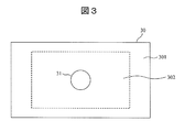
- FIG. 3 shows a plan view of the lower heating body 30.
- the upper heating body 20 has a structure in which the temperature of the first region 201 that is the peripheral portion of the upper heating body 20 is higher than the temperature of the second region 202 including the central portion.
- the lower heating body 30 has a structure in which the temperature of the first region 301 that is the peripheral portion of the lower heating body 30 is higher than the temperature of the second region 302 including the central portion. .
- heat easily escapes and the temperature tends to decrease.
- the upper heating body 20 is a glass heater.
- the glass heater has a structure in which a transparent heating element is sandwiched between two glasses.
- a glass heater is created by vapor-depositing a transparent heating element on glass.
- the transparent heating elements in the first region 201 where the temperature easily escapes are densely arranged, and the transparent region in the second region 202 is transparent.
- the heating elements may be arranged sparsely.
- the heat generation amount in the first region 201 is larger than the heat generation amount in the second region 202.
- the temperature variation between the first region 201 and the second region 202 can be reduced, and the temperature of the plurality of wells of the sample container 10 held inside can be kept uniform.
- the upper heating body 20 is not limited to the above configuration as long as the heat generation amount in the first region 201 is larger than the heat generation amount in the second region 202.
- a transparent heating element is vapor deposited on glass.
- the amount of heat generated may be changed by changing the thickness of the film-like transparent heating element in the second region 202 relative to the thickness of the film-like transparent heating element in the first region 201.
- the thickness of the film-like transparent heating element in the first region 201 may be larger than the thickness of the film-like transparent heating element in the second region 202.
- the heat generation amount in the first region 201 is larger than the heat generation amount in the second region 202.
- the temperature variation between the first region 201 and the second region 202 can be reduced, and the temperature of the plurality of wells of the sample container 10 held inside can be kept uniform.
- the lower heating body 30 is a heater made of an opaque material.
- the heater is created by disposing nichrome wire on a metal plate.
- the lower heating body 30 has a structure in which the heat generation amount in the first region 301 is larger than the heat generation amount in the second region 302.
- the heating elements in the first region 301 where the temperature easily escapes are arranged densely, and the heating elements in the second region 302 are sparse. You may arrange in.
- the interval between adjacent nichrome wires (linear heating elements) in the first region 301 is smaller than the interval between adjacent nichrome wires in the second region 302.
- the upper side heating body 20 and the lower side heating body 30 are not limited to said structure. As long as it has a structure in which the heat generation amount in the first regions 201 and 301 is larger than the heat generation amount in the second regions 202 and 302, the upper heating body 20 and the lower heating body 30 have other configurations than the above. May be adopted.
- the upper side heating body 20 and the lower side heating body 30 have a size sufficiently larger than the sample container 10 so that the variation in the heat generation amount does not affect the sample container 10.
- the upper heating body 20 and the lower heating body 30 have sizes that cover the sample container 10.
- FIG. 2 shows an example of the size relationship between the upper heating body 20 and the sample container 10.
- the sample container 10 is moved by the XY stage 90 in the X-axis direction and the Y-axis direction (in a range indicated by dotted lines). Therefore, in a plan view, the planar sizes of the upper heating body 20 and the lower heating body 30 are larger than the movement ranges of the sample container 10 in the X-axis direction and the Y-axis direction. As an example, the planar size of the upper heating body 20 and the lower heating body 30 is four times or more the planar size of the sample container 10.
- the imaging device includes a lighting device 40 and an imaging device 50. As shown in FIG. 1, the lighting device 40 is disposed above the upper heating body 20. Further, the imaging device 50 is disposed below the lower heating body 30.
- the upper heating body 20 is a glass heater, it is possible to irradiate the sample container 10 with light even if the lighting device 40 is disposed above the upper heating body 20. Further, in the case of the glass heater, there is no need to provide a hole for the lighting device 40, and there is an advantage that the temperature condition of the well of the sample container 10 can be easily maintained.
- the lower heating body 30 is a heater made of an opaque material
- the lower heating body 30 is provided with a hole 31 for the imaging device 50.
- the mounting table 91 of the XY stage 90 is provided with a hole 92 for the imaging device 50.
- the lens of the imaging device 50 is inserted into the hole 31 of the lower heating body 30.
- the imaging device 50 can image the sample container 10 through the hole 31 and the hole 92. Thereby, it is possible to image the sample container 10 by the imaging device 50 while maintaining the temperature of the sample container 10 with the temperature adjusting device.
- the hole 31 for the imaging device 50 is provided in the lower side heating body 30, the lower side heating body 30 exists in the position fixed without moving. Only the sample container 10 is moved by the XY stage 90.
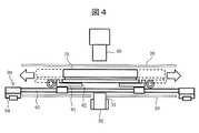
- FIG. 4 is a cross-sectional view showing another example of the XY stage in the bacteria susceptibility measuring apparatus according to the first embodiment.
- the XY stage 90 may include a rail 93 for moving the mounting table 91 in the X-axis direction and the Y-axis direction, and a drive mechanism 94 that drives the movement of the mounting table 91.
- the drive mechanism 94 for driving the movement of the sample container 10 may be disposed outside the upper heating body 20 and the lower heating body 30.
- the configuration of the XY stage is not limited to the two configurations described above, and can be changed as appropriate.
- the XY stage 90 can have various configurations.
- the distance between the upper heating body 20 and the sample container 10 and the distance between the lower heating body 30 and the sample container 10 are as follows. It varies depending on the configuration of the XY stage 90 and the like. Considering these, the temperature of the first region 201 of the upper heating body 20, the temperature of the second region 202 of the upper heating body 20, the temperature of the first region 301 of the lower heating body 30, and The temperature of the second region 302 of the lower heating body 30 may be set as appropriate.
- FIG. 5 is a cross-sectional view showing the configuration of the bacteria susceptibility measuring apparatus according to the second embodiment.
- the XY stage 90 is omitted in order to briefly explain the configuration of the invention.
- the lower heating body 30 includes a plate 32 made of a material having thermal conductivity and a heating element 33.
- An example of the plate 32 is a metal plate with good thermal conductivity.
- the heating element 33 is disposed, for example, in the first region 301 of the lower heating body 30.
- the temperature of the first region 301 where the temperature easily escapes is made higher than that of the second region 302. Can do.
- the temperature adjustment device can be configured with a simple structure in which the heating element itself is not disposed directly under the sample container 10.
- the upper heating body 20 may include a plate made of a material having good thermal conductivity and a heating element. In this case, it is necessary to provide a hole for the lighting device 40 in the upper heating body 20.
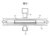
- FIG. 6 is a cross-sectional view showing the configuration of the bacteria susceptibility measuring apparatus according to the third embodiment.
- the XY stage 90 is omitted in order to briefly explain the configuration of the invention.
- the lower heating body 30 may be composed of the glass heater described above.
- the glass heater is created by depositing a transparent heating element on glass.
- the transparent heating elements in the first region 301 where the temperature easily escapes are densely arranged, and the transparent region in the second region 302 is transparent.
- the heating elements may be arranged sparsely. As an example, when the transparent heating element is linearly deposited on the glass, the interval between the adjacent linear transparent heating elements in the first region 301 is the same as that of the adjacent linear transparent heating element in the second region 302. Less than the interval between.
- the thickness of the transparent heating element in the first region 301 may be larger than the thickness of the transparent heating element in the second region 302. Good.
- the present embodiment it is possible to image the sample container 10 with the imaging device 50 without providing a hole for the imaging device 50 in the lower heating body 30. Moreover, there is an advantage that the amount of heat generated by the lower warming body 30 can be made more uniform by not forming a hole in the lower warming body 30.
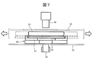
- FIG. 7 is sectional drawing which shows the structure of the bacteria sensitivity measuring apparatus which concerns on 4th Example.
- the upper heating body 20 is configured by the glass heater described above. Furthermore, the upper heating body 20 is connected to the XY stage 90. Therefore, the upper heating body 20 moves in the X-axis direction and the Y-axis direction (in the range indicated by the dotted line) together with the sample container 10 by the movement of the XY stage 90.
- the planar size of the upper warming body 20 is the same as the planar size of the sample container 10. Or a slightly larger size. That is, it is not necessary to make the plane size of the upper heating body 20 large enough to cover the moving range of the sample container 10, and the plane size of the upper heating body 20 is designed to be smaller than that of the above-described embodiment. be able to.
- the planar size of the lower heating body 30 is larger than the movement range of the sample container 10 in the X-axis direction and the Y-axis direction. .
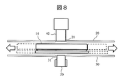
- FIG. 8 is sectional drawing which shows the structure of the bacteria sensitivity measuring apparatus which concerns on 5th Example.
- the XY stage 90 is omitted in order to briefly explain the configuration of the invention.
- the upper heating body 20 is a heater made of an opaque material.
- the heater is created by disposing nichrome wire on a metal plate.
- the upper heating body 20 has a structure in which the heat generation amount in the first region 201 is larger than the heat generation amount in the second region 202.
- the heating elements in the first region 201 where the temperature easily escapes are densely arranged, and the heating elements in the second region 202 are sparse. You may arrange in. For example, the distance between adjacent nichrome lines in the first region 201 is smaller than the distance between adjacent nichrome lines in the second region 202. As a result, the temperature variation between the first region 201 and the second region 202 can be reduced, and the temperature of the plurality of wells of the sample container 10 held inside can be kept uniform.
- the upper heating body 20 since the upper heating body 20 is made of an opaque material, the upper heating body 20 has a hole 21 for the lighting device 40.
- the illumination device 40 can illuminate the sample container 10 through the hole 21.
- the size of the upper heating body 20 and the lower heating body 30 is larger than the movement range of the sample container 10 in the X axis direction and the Y axis direction. .
- FIG. 9 is sectional drawing which shows the structure of the bacteria sensitivity measuring apparatus which concerns on 6th Example.
- the configuration in which the hole is provided in at least one of the upper heating body 20 and the lower heating body 30 has been described.
- the upper warming body 20 and the lower warming body 30 are arranged with respect to the sample container so that the temperature drop at the ends thereof does not affect the amount of bacteria grown in the sample container 10. It needs to be large enough.
- the measuring device itself is also enlarged.
- a configuration in which the positions of the upper heating body 20 and the lower heating body 30 and the position of the sample container 10 are fixed and the illumination device 40 and the imaging device 50 are moved may be employed.
- the sample container 10 is placed on a stage 95 that does not move in the X-axis direction and the Y-axis direction.
- the illumination device 40 and the imaging device 50 are connected to each other and provided as an integrated optical measurement unit.
- the illumination device 40 and the imaging device 50 are each supported by an XY stage (not shown). By this XY stage, the illumination device 40 and the imaging device 50 move together in the X-axis direction and the Y-axis direction.
- the upper heating body 20 and the lower heating body 30 have the glass heater structure described above. Thereby, all the wells in the sample container 10 can be measured by the integrated optical measurement unit.
- planar sizes of both the upper heating body 20 and the lower heating body 30 are not necessary to make the planar sizes of both the upper heating body 20 and the lower heating body 30 large enough to cover the moving range of the sample container 10.
- the planar sizes of both the upper heating body 20 and the lower heating body 30 can be designed to be smaller than in the above-described embodiment. Therefore, the bacteria susceptibility measuring apparatus can be downsized.
- FIG. 10 is an example of an inspection apparatus provided with the bacteria susceptibility measuring apparatus of the first to sixth embodiments.
- the inspection apparatus includes a stack unit 80.
- the stack unit 80 is a thermostatic chamber that can simultaneously culture a plurality of sample containers 10.
- the stack unit 80 has a mechanism in which the storage position of the sample container 10 can be moved.
- the stack unit 80 can freely select the sample container 10 to be measured and supply it to the transport unit described below.
- the inspection apparatus includes a preparation chamber 100 that can supply the sample container 10 to the stack unit 80 and discharge the sample container 10 from the stack unit 80.
- the sample container 10 is supplied to the preparation chamber 100 using the first transfer unit 130.
- the sample container 10 can be heated.
- the sample container 10 is supplied to the stack unit 80. Thereby, the sample container 10 can be taken in and out without lowering the temperature of the measurement chamber and the stack unit 80.
- a second transport unit that transports the sample container 10 is provided between the preparation chamber 100 and the stack unit 80.
- a third transfer unit 120 is provided between the XY stage 90 and the stack unit 80. Only the sample container 10 to be measured can be transported from the stack unit 80 to the XY stage 90 using the third transport unit 120. In addition, the third transport unit 120 transports the sample container 10 whose measurement has been completed to the stack unit 80 again.
- the inspection device includes a control personal computer 110.
- the control personal computer 110 can manage the culture start time.
- the control personal computer 110 can control the entire inspection apparatus.
- the control personal computer 110 can control the conveyance of the sample container 10, the start of measurement, and the like without stopping the measurement sequence, and can always be inspected.
- the above-described bacterial susceptibility measuring apparatus includes a temperature adjusting device for adjusting the temperature of the sample container 10 to promote bacterial culture, and an imaging device for optically measuring the cultured bacteria.
- the bacteria susceptibility measuring apparatus includes an XY stage that can move the sample container 10 or the imaging device in the X-axis direction and the Y-axis direction in order to measure a plurality of wells in the sample container 10.
- the temperature adjustment device includes the upper heating body 20 and the lower heating body 30.
- Each of the upper heating body 20 and the lower heating body 30 has a structure in which there is a difference in calorific value between the peripheral portion and the central portion, or there is a difference in temperature between the peripheral portion and the central portion.
- the sample container 10 can be imaged by the imaging device while maintaining the same temperature condition.
- the amount of bacteria grown in the sample container 10 cultured under a uniform temperature condition can be measured every predetermined time, and the drug sensitivity can be determined from the change in the amount.
- inspection apparatus which can judge the result of a sensitivity test in a short time can be provided by analyzing the change of the amount of bacterial growth.
- the present invention is not limited to the above-described embodiments, and includes various modifications.
- the above embodiments have been described in detail for easy understanding of the present invention, and are not necessarily limited to those having all the configurations described.
- a part of the configuration of one embodiment can be replaced with the configuration of another embodiment.
- the structure of another Example can also be added to the structure of a certain Example.
- another configuration can be added, deleted, or replaced.
Landscapes
- Chemical & Material Sciences (AREA)
- Health & Medical Sciences (AREA)
- Life Sciences & Earth Sciences (AREA)
- Engineering & Computer Science (AREA)
- Bioinformatics & Cheminformatics (AREA)
- Wood Science & Technology (AREA)
- Zoology (AREA)
- Organic Chemistry (AREA)
- General Health & Medical Sciences (AREA)
- Biochemistry (AREA)
- Analytical Chemistry (AREA)
- Biomedical Technology (AREA)
- Biotechnology (AREA)
- Sustainable Development (AREA)
- General Engineering & Computer Science (AREA)
- Microbiology (AREA)
- Genetics & Genomics (AREA)
- Physics & Mathematics (AREA)
- Pathology (AREA)
- Surgery (AREA)
- Thermal Sciences (AREA)
- General Physics & Mathematics (AREA)
- Immunology (AREA)
- Signal Processing (AREA)
- Oral & Maxillofacial Surgery (AREA)
- Nuclear Medicine, Radiotherapy & Molecular Imaging (AREA)
- Heart & Thoracic Surgery (AREA)
- Medical Informatics (AREA)
- Molecular Biology (AREA)
- Animal Behavior & Ethology (AREA)
- Public Health (AREA)
- Veterinary Medicine (AREA)
- Multimedia (AREA)
- Apparatus Associated With Microorganisms And Enzymes (AREA)
- Medicinal Chemistry (AREA)
- Sampling And Sample Adjustment (AREA)
Priority Applications (4)
| Application Number | Priority Date | Filing Date | Title |
|---|---|---|---|
| JP2017514036A JP6437103B2 (ja) | 2015-04-23 | 2016-03-28 | 感受性計測装置及び検査装置 |
| EP16782952.2A EP3287515B1 (de) | 2015-04-23 | 2016-03-28 | Vorrichtung zur empfindlichkeitsmessung und inspektionsvorrichtung |
| CN201680018671.8A CN107406815A (zh) | 2015-04-23 | 2016-03-28 | 感受性测量装置及检查装置 |
| US15/568,093 US10624712B2 (en) | 2015-04-23 | 2016-03-28 | Sensitivity measuring device and inspection device |
Applications Claiming Priority (2)
| Application Number | Priority Date | Filing Date | Title |
|---|---|---|---|
| JP2015088772 | 2015-04-23 | ||
| JP2015-088772 | 2015-04-23 |
Publications (1)
| Publication Number | Publication Date |
|---|---|
| WO2016170930A1 true WO2016170930A1 (ja) | 2016-10-27 |
Family
ID=57143038
Family Applications (1)
| Application Number | Title | Priority Date | Filing Date |
|---|---|---|---|
| PCT/JP2016/059977 Ceased WO2016170930A1 (ja) | 2015-04-23 | 2016-03-28 | 感受性計測装置及び検査装置 |
Country Status (5)
| Country | Link |
|---|---|
| US (1) | US10624712B2 (de) |
| EP (1) | EP3287515B1 (de) |
| JP (1) | JP6437103B2 (de) |
| CN (1) | CN107406815A (de) |
| WO (1) | WO2016170930A1 (de) |
Families Citing this family (2)
| Publication number | Priority date | Publication date | Assignee | Title |
|---|---|---|---|---|
| CN112400023A (zh) * | 2019-03-14 | 2021-02-23 | 株式会社日立高新技术 | 药剂敏感性检查方法 |
| KR102669824B1 (ko) * | 2023-08-11 | 2024-05-27 | 홍종일 | 미생물 배양액 공급 시스템 |
Citations (3)
| Publication number | Priority date | Publication date | Assignee | Title |
|---|---|---|---|---|
| JP2009093126A (ja) * | 2007-10-05 | 2009-04-30 | Kunio Isono | 発熱源を一体化させて熱効率の良いスライドガラス基板又はシャーレ |
| JP2009201509A (ja) * | 2008-02-01 | 2009-09-10 | Kunio Isono | 透明導電膜加工からなる培養容器とその製造方法 |
| JP2010091738A (ja) * | 2008-10-07 | 2010-04-22 | Olympus Corp | 画像取得装置 |
Family Cites Families (13)
| Publication number | Priority date | Publication date | Assignee | Title |
|---|---|---|---|---|
| US5985214A (en) * | 1997-05-16 | 1999-11-16 | Aurora Biosciences Corporation | Systems and methods for rapidly identifying useful chemicals in liquid samples |
| US7423750B2 (en) * | 2001-11-29 | 2008-09-09 | Applera Corporation | Configurations, systems, and methods for optical scanning with at least one first relative angular motion and at least one second angular motion or at least one linear motion |
| US7272252B2 (en) * | 2002-06-12 | 2007-09-18 | Clarient, Inc. | Automated system for combining bright field and fluorescent microscopy |
| JP4354446B2 (ja) * | 2005-10-13 | 2009-10-28 | 株式会社東海ヒット | 顕微鏡ステージ及び顕微鏡観察用ユニット |
| EP1989331A2 (de) | 2006-02-07 | 2008-11-12 | Wafergen, Inc. | Temperaturregulierte kulturplatten |
| JP4756695B2 (ja) * | 2006-02-20 | 2011-08-24 | コバレントマテリアル株式会社 | 面状ヒータ |
| JP5307539B2 (ja) | 2006-05-31 | 2013-10-02 | オリンパス株式会社 | 生体試料撮像方法および生体試料撮像装置 |
| KR101465701B1 (ko) * | 2008-01-22 | 2014-11-28 | 삼성전자 주식회사 | 핵산 증폭 장치 |
| US20120034596A1 (en) | 2009-04-22 | 2012-02-09 | Pan-Systech Gmbh | Device for automatically cultivating cells in parallel |
| JP5443950B2 (ja) | 2009-11-13 | 2014-03-19 | 株式会社日立ハイテクノロジーズ | 細菌コロニー釣菌装置及びその方法 |
| US9109194B2 (en) | 2009-11-05 | 2015-08-18 | Hitachi High-Technologies Corporation | Device for harvesting bacterial colony and method therefor |
| JP6042130B2 (ja) * | 2012-07-31 | 2016-12-14 | シスメックス株式会社 | 検体移し替え装置、検体処理システムおよび検体移し替え方法 |
| JP5954079B2 (ja) * | 2012-09-25 | 2016-07-20 | ソニー株式会社 | 培養観察装置及び培養観察方法 |
-
2016
- 2016-03-28 EP EP16782952.2A patent/EP3287515B1/de active Active
- 2016-03-28 WO PCT/JP2016/059977 patent/WO2016170930A1/ja not_active Ceased
- 2016-03-28 US US15/568,093 patent/US10624712B2/en active Active
- 2016-03-28 CN CN201680018671.8A patent/CN107406815A/zh active Pending
- 2016-03-28 JP JP2017514036A patent/JP6437103B2/ja active Active
Patent Citations (3)
| Publication number | Priority date | Publication date | Assignee | Title |
|---|---|---|---|---|
| JP2009093126A (ja) * | 2007-10-05 | 2009-04-30 | Kunio Isono | 発熱源を一体化させて熱効率の良いスライドガラス基板又はシャーレ |
| JP2009201509A (ja) * | 2008-02-01 | 2009-09-10 | Kunio Isono | 透明導電膜加工からなる培養容器とその製造方法 |
| JP2010091738A (ja) * | 2008-10-07 | 2010-04-22 | Olympus Corp | 画像取得装置 |
Non-Patent Citations (1)
| Title |
|---|
| See also references of EP3287515A4 * |
Also Published As
| Publication number | Publication date |
|---|---|
| CN107406815A (zh) | 2017-11-28 |
| EP3287515B1 (de) | 2019-10-23 |
| EP3287515A1 (de) | 2018-02-28 |
| JPWO2016170930A1 (ja) | 2018-01-11 |
| EP3287515A4 (de) | 2018-11-07 |
| US20180079996A1 (en) | 2018-03-22 |
| JP6437103B2 (ja) | 2018-12-12 |
| US10624712B2 (en) | 2020-04-21 |
Similar Documents
| Publication | Publication Date | Title |
|---|---|---|
| US20240295572A1 (en) | Incubation system and method for automated cell culture and testing | |
| US20210261903A1 (en) | Cell culture incubators with integrated imaging systems | |
| US20200148995A1 (en) | Device and Method for Automatic Processing of Culture Plates for Microbiological Samples | |
| CN108300663B (zh) | 细胞培养监测系统及培养监测方法 | |
| KR20110131371A (ko) | 형광측정용 세포 추적 장치 | |
| JP6437103B2 (ja) | 感受性計測装置及び検査装置 | |
| KR101808063B1 (ko) | 세포 배양 플레이트를 구비하는 세포 배양장치 | |
| CN116218654A (zh) | 一种微流控芯片、制备方法及细菌耐药性的检测方法 | |
| US20150212070A1 (en) | Low-Cost Portable Microfluidic System for Cell Migration | |
| JP7411751B2 (ja) | 培養容器ラック及び分析装置 | |
| Kaech et al. | Long-term time-lapse imaging of developing hippocampal neurons in culture | |
| Llerena et al. | Testing epithelial permeability in fetal tissue-derived enteroids | |
| WO2016009777A1 (ja) | 温度調整容器 | |
| CN209043906U (zh) | 一种生化检测装置 | |
| Petersen et al. | State-of-the-Art and Problems in Development of Automated Screening Systems in Personalized Medicine and Oncology | |
| CN118671136A (zh) | 一种可视差式扫描量热仪 | |
| JP2011125328A (ja) | 標本の活性計測用器材セット及び活性計測装置・方法 | |
| JP2011092184A (ja) | 標本の活性計測用器材セット及び活性計測装置・方法 | |
| JP2011125327A (ja) | 標本の活性計測用器材セット及び活性計測装置・方法 | |
| JP2011097920A (ja) | 標本の活性計測用器材セット及び活性計測装置・方法 | |
| WO2011051738A1 (en) | Annealing incubator | |
| CN103712912A (zh) | 一种用于测量固体药物固有溶出度及溶出度的分析仪 |
Legal Events
| Date | Code | Title | Description |
|---|---|---|---|
| 121 | Ep: the epo has been informed by wipo that ep was designated in this application |
Ref document number: 16782952 Country of ref document: EP Kind code of ref document: A1 |
|
| ENP | Entry into the national phase |
Ref document number: 2017514036 Country of ref document: JP Kind code of ref document: A |
|
| WWE | Wipo information: entry into national phase |
Ref document number: 15568093 Country of ref document: US |
|
| REEP | Request for entry into the european phase |
Ref document number: 2016782952 Country of ref document: EP |
|
| NENP | Non-entry into the national phase |
Ref country code: DE |