WO2016174889A1 - Noyau statorique et stator pour machine électrique tournante et machine électrique tournante - Google Patents
Noyau statorique et stator pour machine électrique tournante et machine électrique tournante Download PDFInfo
- Publication number
- WO2016174889A1 WO2016174889A1 PCT/JP2016/053158 JP2016053158W WO2016174889A1 WO 2016174889 A1 WO2016174889 A1 WO 2016174889A1 JP 2016053158 W JP2016053158 W JP 2016053158W WO 2016174889 A1 WO2016174889 A1 WO 2016174889A1
- Authority
- WO
- WIPO (PCT)
- Prior art keywords
- stator core
- members
- contact
- radial
- engagement
- Prior art date
- Legal status (The legal status is an assumption and is not a legal conclusion. Google has not performed a legal analysis and makes no representation as to the accuracy of the status listed.)
- Ceased
Links
Images


Classifications
-
- H—ELECTRICITY
- H02—GENERATION; CONVERSION OR DISTRIBUTION OF ELECTRIC POWER
- H02K—DYNAMO-ELECTRIC MACHINES
- H02K1/00—Details of the magnetic circuit
- H02K1/06—Details of the magnetic circuit characterised by the shape, form or construction
- H02K1/12—Stationary parts of the magnetic circuit
- H02K1/14—Stator cores with salient poles
- H02K1/146—Stator cores with salient poles consisting of a generally annular yoke with salient poles
- H02K1/148—Sectional cores
-
- H—ELECTRICITY
- H02—GENERATION; CONVERSION OR DISTRIBUTION OF ELECTRIC POWER
- H02K—DYNAMO-ELECTRIC MACHINES
- H02K1/00—Details of the magnetic circuit
- H02K1/06—Details of the magnetic circuit characterised by the shape, form or construction
- H02K1/12—Stationary parts of the magnetic circuit
- H02K1/18—Means for mounting or fastening magnetic stationary parts on to, or to, the stator structures
Definitions
- the present invention relates to a stator core and a stator of a rotating electric machine, and a rotating electric machine.
- Patent Document 1 discloses a split core structure in which a plurality of split core portions are assembled by providing a fixing member such as a pin or a screw so as to penetrate each split core portion in the axial direction.
- the present invention provides a stator core and a stator for a rotating electrical machine having a split core structure that can avoid the complication of the manufacturing process and improve the characteristics of the rotating electrical machine with a simple structure, and the rotating electrical machine. With the goal.
- the present invention can employ the following configurations.
- a stator core for a rotating electric machine is A first tooth portion extending in one of the radial inner direction and the outer direction, a first engagement portion located on both sides in the circumferential direction of the first tooth portion, and a radial inner direction and an outer direction.
- a plurality of first members having a base portion located on the other side and arranged side by side in the circumferential direction; A second tooth portion extending in one of the radial directions; and a second engagement portion engaging with the two first engagement portions adjacent to each other in the circumferential direction, wherein the second tooth portions are adjacent to each other.
- the base portions of the plurality of first members arranged side by side in the circumferential direction are configured to contact the base portions of the plurality of first members so as to push the base portions from the other side in the radial direction toward the one side.
- a support member, The first engaging portion and the second engaging portion are when the base portion of the plurality of first members is pressed toward the one from the other side in the radial direction by contacting the support member.
- the two first engaging portions and the second engaging portion that are adjacent to each other in the circumferential direction are engaged with each other so that the movement of the second member in the radial direction is limited. ing.
- the first engagement portion and the second engagement portion are directed from the other side in the radial direction toward one side by the base portions of the plurality of first members coming into contact with the support member.
- the two first engaging portions and the second engaging portions that are adjacent to each other in the circumferential direction are engaged to limit the movement of the second member in one of the radial directions.
- the relative positional relationship between the plurality of first members and the plurality of second members is fixed by installing the support member so as to contact the base portions of the plurality of first teeth portions arranged side by side in the circumferential direction.
- the second tooth portion and the first tooth portion are provided so as to extend in one of the radial directions (for example, the outer direction).
- the first engaging part is located on both sides in the circumferential direction of the first tooth part.
- the second engaging portion engages with both of the two first engaging portions adjacent to each other in the circumferential direction. Therefore, the main magnetic flux path when the magnetic flux flows between the first tooth portion and the second tooth portion is, for example, the first tooth portion and at least one of the first engagement portion and the second engagement portion. , Formed to pass through the second tooth.
- the contact portion between the support member and the base portion is located on the other radial direction of the first tooth portion (for example, inward) and is not included in the main magnetic flux path. Therefore, according to the stator core of (1), unlike the conventional split core structure in which the fixing member is provided in the split core portion, the influence of the support member on the magnetic flux in the main magnetic flux path is suppressed.
- the support member when the support member comes into contact with the base portions of the plurality of first members, the support member moves the base portions of the plurality of first members to one of the radial directions (for example, outward). There is a force to push it.
- the first engagement portion and the second engagement portion engage with each other, so that one of the second members in the radial direction (for example, the outer side) Movement to the direction is limited. As a result, the force with which the first member and the second member come into contact in the radial direction is increased.
- the magnetic resistance of the air gap is much larger than the magnetic resistance in the stator core.
- the magnetic resistance of the air gap is several thousand times (for example, about 5000 times) the magnetic resistance of a stator core made of a general electromagnetic steel sheet.
- the stator core (1) since the generation of air gaps in the main magnetic flux path is suppressed, the magnetic resistance of the main magnetic flux path is reduced. Therefore, the stator core (1) can flow more magnetic flux.
- the manufacturing process is complicated by a simple structure while enjoying the merit of the split core structure that reduces the copper loss by improving the space factor of the winding.
- the characteristics of the rotating electrical machine can be improved by reducing the magnetic resistance of the main magnetic flux path.
- the base portion is located on the inner side in the radial direction,
- the support member is configured to come into contact with the base portions of the plurality of first members so as to push the base portions of the plurality of first members from the inside in the radial direction toward the outside.
- the first engaging portion and the second engaging portion are rotated when the base portion of the plurality of first members is pushed outward from the inside in the radial direction by contacting the support member.
- the two first engaging portions and the second engaging portions that are adjacent to each other in the direction are engaged with each other, thereby restricting the outward movement of the second member in the radial direction.
- the stator core is used for an outer rotor type rotating electrical machine.
- the stator core of (2) can restrict the radial movement of the second member in the radial direction by the engagement between the first engagement portion and the second engagement portion. Therefore, according to (2), in the stator core used in the outer rotor type rotating electrical machine, the plurality of first members and the plurality of first members are provided without providing the fixing member in the divided core portion as in the conventional divided core structure. The relative positional relationship between the two members can be fixed.
- the stator core of (2), The first member and the second member have two first engagement portions and the second engagement that are adjacent to each other in the circumferential direction when movement of the second member in the radial direction is restricted. It is configured to have a tensile stress acting part in which a tensile stress acts by engagement with the joint part, and at least a part of the tensile stress acting part passes through the stator core from the first tooth part, and It is located in the magnetic flux path to the second teeth part.
- the tensile stress acting part is generated in the first member and the second member by the engagement between the first engaging part and the second engaging part. At least a part of the tensile stress acting part is located in a magnetic flux path from the first tooth part through the stator core to the second tooth part. Therefore, at least a part of the magnetic flux from the first tooth portion through the stator core to the second tooth portion passes through the tensile stress acting portion.
- iron loss due to distortion for example, punching distortion caused by pressing
- the iron loss can be mitigated while enjoying the merit of the split core structure of reducing the copper loss by improving the space factor of the winding, and the characteristics of the rotating electrical machine. Improvements can be made.
- the magnetic resistance of the magnetic flux path (for example, the main magnetic flux path) is more effectively achieved by the surface contact between the first engagement portion and the second engagement portion in the circumferential contact portion. Can be reduced. The characteristics of the rotating electrical machine can be improved more effectively.
- the circumferential contact portion includes a straight line extending from a side where the first engagement portion and the second engagement portion are in contact with each other when viewed in the axial direction of the stator core, and a circumferential center of the second member. An intersection point with a straight line extending in the radial direction through is configured to be located radially inward of the circumferential contact portion.
- stator core of (5) it is possible to increase the force in the circumferential direction on the two first engaging portions adjacent to each other, which is generated when the support member comes into contact with the base portions of the plurality of first members. . Accordingly, it is possible to increase the force with which the second engaging portion engages with the two first engaging portions adjacent to each other. As a result, it is more effectively suppressed that a minute gap is generated at the contact portion between the first member and the second member. The characteristics of the rotating electrical machine can be improved more effectively.
- the stator core according to any one of (1) to (5), The first member is configured such that a gap is generated between the base portions of the first members adjacent in the circumferential direction when the support member contacts the base portions of the plurality of first members. Yes.
- stator core of (6) since the allowable range of the dimensions of the plurality of first members is widened, it is easy to manufacture. Further, since there is a gap, assembly of the stator core (particularly engagement between the first engagement portion and the second engagement portion) is facilitated. Therefore, the complexity of the manufacturing process can be more effectively avoided with a simpler structure.
- the magnetic resistance of the magnetic flux path (for example, the main magnetic path) is more effectively achieved by the surface contact between the first engagement portion and the second engagement portion in the radial contact portion. Can be reduced. The characteristics of the rotating electrical machine can be improved more effectively.
- the stator core according to (7) The first member has a radial direction from a surface on the first member side of the support member to a top surface of the first teeth portion when the support member comes into contact with the base portion of the plurality of first members.
- the length (D) is the radial length (d1) from the surface on the first member side of the support member to the contact surface between the first engagement portion and the second engagement portion in the radial contact portion.
- the radial length (d2) from the contact surface of the first engagement portion and the second engagement portion to the top surface of the second teeth portion in the radial contact portion are configured to be the same.
- stator core of (8) it is easy to align the positions of the top surfaces of the first tooth portion and the second tooth portion in the radial direction. Therefore, the complexity of the manufacturing process can be more effectively avoided with a simpler structure.
- a stator for a rotating electric machine is Any one of the stator cores of (1) to (8); And a winding wound around the first teeth portion and the second teeth portion.
- stator of (9) it is possible to provide a stator capable of avoiding complication of the manufacturing process and improving the characteristics of the rotating electrical machine with a simple structure.
- a rotating electric machine The rotating electric machine is (9) the stator; And a rotor having a permanent magnet portion disposed so as to face the first tooth portion and the second tooth portion of the stator with a gap.
- FIG. 3 is an axial direction view schematically showing a stator core according to an embodiment of the present invention.
- FIG. 6 is an axial direction view schematically showing a state of the stator core before a support member is provided.
- (A) is an axial direction view schematically showing a partially enlarged state of the stator core before the support member is provided, and (b) is the view after the support member is provided.
- FIG. 3 is an axial direction view schematically showing a state of the stator core partially enlarged.
- FIG. 3 is an axial direction view schematically showing a stator core according to an embodiment of the present invention partially enlarged. It is an axial direction view which shows typically the 1st member concerning the embodiment of the present invention.
- FIG. 6 is an axial direction view schematically showing a state of the stator core before a support member is provided.
- (A) is an axial direction view schematically showing a partially enlarged state of the stator core before the support member is provided
- (b) is the view after the support
- FIG. 6 is an axial direction view schematically showing a partially enlarged state of the stator core after a support member is provided.
- A is drawing which shows typically an example of the layout of the board member on the magnetic body board for punching out the board member for manufacture of the 1st member and the 2nd member from a magnetic body board,
- b These are drawings schematically showing another example. It is an axial direction view for showing typically stress distribution in a part of stator core concerning an embodiment of the present invention.
- 1 is an axial view schematically showing a rotating electrical machine according to an embodiment of the present invention. It is an axial direction view seen partially enlarged and showing a stator core concerning other embodiments of the present invention typically. It is an axial direction view seen partially enlarged and showing a stator core concerning other embodiments of the present invention typically. It is an axial direction view seen partially enlarged and showing a stator core concerning other embodiments of the present invention typically. It is an axial direction view seen partially enlarged and showing a stator core concerning other embodiments of the
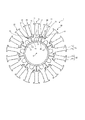
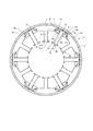
- FIG. 1 is an axial direction view schematically showing a stator core for rotating electrical machines (hereinafter also simply referred to as “stator core”) 1 according to an embodiment of the present invention.
- A indicates the rotation axis of the stator core A.
- the stator core 1 of this embodiment is a stator core for radial gap type rotating electrical machines, and more specifically, is a stator core for an outer rotor type rotating electrical machine.
- the stator core for a rotating electrical machine of the present invention is not limited to this example, and may be a stator core for an inner rotor type rotating electrical machine.
- the stator core 1 includes a plurality of first members 10, a plurality of second members 20, and one support member 30.
- the number of the first members 10 and the second members 20 is nine, and the same number.
- the number of the 1st member 10 and the 2nd member 20 is not specifically limited.
- the plurality of first members 10 are arranged side by side in the circumferential direction.
- Each of the plurality of first members 10 includes a first tooth portion 11 extending in one direction (outward direction) in the radial direction, a first engagement portion 12 positioned on both sides in the circumferential direction of the first tooth portion 11, and a radial direction. And a base portion 13 located on the other direction side (inward direction side).
- the first engaging portion 12 is a portion that engages with a second engaging portion 22 described later.
- the first teeth portion 11 includes a trunk portion 11a that extends in the radial direction, and a circumferential protrusion 11b that projects from both ends in the radial direction (outward side) of the trunk portion 11a to both sides in the circumferential direction. .
- the base portion 13 is provided with a mounting hole constituting portion 13b.
- the mounting hole constituting portion 13b is a concave portion that is recessed in one direction from the other direction side (inward direction side) in the radial direction of the base portion 13 when viewed in the axial direction.
- the attachment hole constituting portion 13 b constitutes an attachment hole surrounded by the first member 10 and the support member 30 by providing the support members 30 for the plurality of first members 10.
- the plurality of second members 20 are arranged side by side in the circumferential direction.
- Each of the plurality of second members 20 includes a second tooth portion 21 extending in one radial direction (outward direction) and a second engagement engaging with the two first engaging portions 12 adjacent to each other in the circumferential direction.
- the second engagement portion 22 is a portion that engages with the first engagement portion 12.
- the second tooth portion 21 includes a body portion 21a that extends in the radial direction, and a circumferential convex portion 21b that protrudes from both ends of the body portion 21a on one side in the radial direction (outward side) in the circumferential direction. .
- the second member 20 is not in contact with the support member 30.
- the number (T) of teeth in the stator core 1 is the sum of the number (t1) of the first teeth portion 11 and the number (t2) of the second teeth portion 21.
- the first member 10 has one first tooth portion 11.
- the second member 20 has one second tooth portion 21.
- the support member 30 has a plurality of first members so as to push the base portions 13 of the plurality of first members 10 arranged side by side in the circumferential direction from the other direction side (inward direction side) in the radial direction toward one direction (outward direction). It is comprised so that the base part 13 of the one member 10 may be contact
- the support member 30 has a cylindrical shape having a space vacated in the axial direction.
- “contact” means that the support member 30 directly contacts the base portion 13 of the plurality of first members 10 without any other member, and that the support member 30 has a plurality of first members. And indirect contact with the base portion 13 of the member 10 via another member.
- the tooth portion and the engaging portion do not necessarily have to be clearly distinguished.
- the engaging parts 12 and 22 may be provided in the base part of the teeth parts 11 and 21. As shown in FIG. In this case, the base part of the teeth parts 11 and 21 is a part of the teeth parts 11 and 21 and a part of the engaging parts 12 and 22.
- P indicates a main magnetic flux path from the first tooth portion 11 to the second tooth portion 21 adjacent to the first tooth portion 11.
- the main magnetic flux path P passes through the first tooth portion 11, at least one of the first engaging portion 12 and the second engaging portion 22, and the second tooth portion 12.
- the main magnetic flux path P is a part of the magnetic flux path from the first tooth portion 11 through the stator core 1 to the second tooth portion 12.
- the magnetic resistance of the main magnetic flux path P is smaller than the magnetic resistance of the magnetic flux path that passes through other portions.
- the main magnetic flux path P does not necessarily need to be configured so that all of the magnetic flux from the first tooth portion 11 to the second tooth portion 21 passes.
- a part of the magnetic flux from the first tooth portion 11 to the second tooth portion 21 may pass through a portion other than the main magnetic flux path P.
- the main magnetic flux path P does not pass through the support member 30.
- the first engaging portion 12 and the second engaging portion 22 are arranged in one direction (outside) from the other direction side (inward direction side) in the radial direction by the base portions 13 of the plurality of first members 10 coming into contact with the support member 30.
- the one direction in the radial direction of the second member 20
- It is configured to restrict movement in the outward direction.
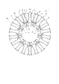
- FIG. 2 is an axial direction view schematically showing the state of the stator core 1 before the support member 30 is provided.
- the plurality of first members 10 and the plurality of second members 20 are alternately arranged in the circumferential direction.
- the plurality of first members 10 and the plurality of second members 20 are arranged such that the second teeth portion 21 is located between the first teeth portions 11 of the first members 10 adjacent to each other in the circumferential direction. Yes.
- the support member 30 is not yet provided.
- the broken line indicates the position of the support member 30 when the support member 30 is provided on the stator core 1.
- the second engaging portion 22 is engaged with the first engaging portions 12 adjacent to each other in the circumferential direction.
- the first engagement portion 12 and the second engagement portion 22 are engaged relatively gently. Therefore, the support member-side surface 13a (inner peripheral surface) of the base portion 13 of the plurality of first members 10 is more in the radial direction than the position where the teeth-side surface 30a (outer peripheral surface) of the support member 30 is to be disposed. Located on the direction side (inward direction side).
- the support member 30 is disposed so that the support member 30 contacts the base portions 13 of the plurality of first members 10. Thereby, the supporting member 30 pushes the base part 13 of the some 1st member 10 toward one direction (outward direction) from the other direction side (inward direction side) of radial direction. As a result, each of the plurality of first members 10 moves in one radial direction (outward direction), and the two first engaging portions 12 and the second engaging portions 22 that are adjacent to each other in the circumferential direction are engaged. Match. Specifically, the two first engaging portions 12 and the second engaging portions 22 adjacent to each other in the circumferential direction are more strongly engaged (see FIG. 1).
- the movement to the one direction (outward direction) of the radial direction of the 2nd member 20 is restrict
- the relative positional relationship between the plurality of first members 10 and the plurality of second members 20 is fixed.
- the relative positional relationship in the radial direction and the circumferential direction of the plurality of first members 10 and the plurality of second members 20 is fixed. Accordingly, the plurality of first members 10 and the plurality of second members 20 are supported by the support member 30.
- FIG. 3A is an axial direction view schematically showing a partially enlarged state of the stator core 1 before the support member 30 is provided.
- FIG. 3B is an axial direction view schematically showing a partially enlarged state of the stator core 1 after the support member 30 is provided.
- Each of the first engaging portions 12 positioned on both sides in the circumferential direction of the first member 10 has a radial contact portion 12a facing in one radial direction (outward direction).
- the second engaging portion 22 has a radial contact portion 22a facing in the other radial direction (inward direction).
- the two adjacent radial contact portions 12a and the radial contact portion 22a are in direct contact with each other in the radial direction.
- the two adjacent radial contact portions 12a and the radial contact portion 22a are in surface contact with each other in the radial direction.
- Each of the 1st engaging parts 12 located in the circumferential direction both sides of the 1st member 10 has the circumferential direction contact part 12b.
- the circumferential direction contact part 12b faces the direction of the 1st teeth part 11 of the 1st member 10 in which the circumferential direction contact part 12b was provided in the circumferential direction.
- the second engaging portion 22 has a circumferential contact portion 22b.
- the circumferential contact portion 22b faces in the circumferential direction toward the second tooth portion 21 of the second member 20 provided with the circumferential contact portion 22b.
- the circumferential contact portion 12b and the circumferential contact portion 22b are in direct contact with each other in the circumferential direction.
- the circumferential contact portion 12b and the circumferential contact portion 22b are in surface contact with each other in the circumferential direction.
- FIG. 3A shows a state in which the support member 30 is not provided, as in FIG. From this state, a state in which the support member 30 is provided will be described with reference to FIG.
- linear arrows schematically indicate the direction and magnitude of the force applied to the first member 10 and the second member 20.
- a force F directed in one radial direction (outward direction) is applied to the first member 10.
- the force F indicates the force at the center position in the circumferential direction of the first member 10. Since the first engagement portion 12 is a part of the first member 10, a force J having the same direction as the force F is applied to the first engagement portion 12. Since the circumferential center position of the first member 10 is different from the circumferential position, the force J is not a force along the radial direction.
- the force J is divided into a circumferential component Jc and a radial component Jr. That is, forces Jc and Jr are applied from the first engagement portion 12 to the second engagement portion 22.
- reaction forces Jc ′ and Jr ′ against the forces Jc and Jr are applied from the second engaging portion 22 to the first engaging portion 12.
- the force H indicates the force with which the second member 20 is pushed in the radial direction by the first member 10 at the circumferential center position of the second member 20.
- a reaction force H ′ against the force H is applied from the second member 20 to the first member 10.
- the two adjacent first engagement portions 12 apply to the second engagement portion 22 forces Jc that are directed in opposite directions (forces Jc that are directed away from each other).
- a reaction force Jc ′ with respect to the force Jc (force Jc ′ toward each other) is applied from the second engagement portion 22 to the first engagement portion 12.
- the first engagement portion 12 and the second engagement portion 22 are engaged.
- the radial movement of the second member 20 is limited.
- the first engagement portion 12 applies a force (Jr, H) to the second engagement portion 22.
- a reaction force (Jr ′, H ′) against the force (Jr, H) is applied from the second engagement portion 22 to the first engagement portion 12.
- the first engaging portion 12 and the second engaging portion 22 are in close contact with each other in the circumferential direction at the circumferential contact portions 12b and 22b. Moreover, in the radial direction contact parts 12a and 22a, the 1st engaging part 12 and the 2nd engaging part 22 closely_contact
- the main magnetic flux path passing through at least one of the first tooth portion 11, the first engaging portion 12, and the second engaging portion 22 and the second tooth portion 21 is the first member 10 and the second member.
- the member 20 is composed of only two types of members.
- a fixing member such as a screw or a pin is disposed in a main magnetic flux path that passes through the second tooth portion 21 and at least one of the first tooth portion 11, the first engaging portion 12, and the second engaging portion 22. Absent.
- Each of the first member 10 and the second member 20 constituting the main magnetic flux path has tooth portions 11 and 21. That is, all of the two types of members constituting the main magnetic flux path have the tooth portions 11 and 21.
- the main magnetic flux path composed of only two types of members 10 and 20 each having the tooth portions 11 and 21, the first engaging portion 12 and the first engaging portion 12 caused by the pressing of the supporting member 30 against the first member 10.
- the movement of the second member 20 in the radial direction is restricted by the engagement of the two engaging portions 22, and thereby the two types of members 10 and 20 are configured to be in close contact with each other. Therefore, the magnetic resistance of the main magnetic flux path is reduced.
- the first member 10 and the second member 20 have the first engagement portion 12 and the second engagement portion 22 engaged by the engagement of the first engagement portion 12 and the second engagement portion 22.
- the circumferential direction is between the engaging portion of one of the first member 10 and the second member 20 and the other of the first member 10 and the second member 20.
- the gap Gp and the radial gap Gr are formed.
- a gap Gr is generated.
- the first member and the second member are not limited to this example.
- the first member and the second member have, for example, a circumferential gap and a radial gap between the first member and the second member when the first engagement portion and the second engagement portion are engaged. Configured. As a result, tolerances at the time of design and errors at the time of manufacture can be allowed while maintaining the characteristics of the rotating electrical machine. The complexity of the manufacturing process can be avoided and the characteristics of the rotating electrical machine can be improved.
- FIG. 4 is an axial direction view schematically showing a stator core according to an embodiment of the present invention partially enlarged.
- the circumferential contact portions 12b and 22b are, as viewed in the axial direction of the stator core 1, a straight line N extending the side M where the first engagement portion 12 and the second engagement portion 22 are in contact with each other, and the second member 20.
- the intersection R with the straight line Q extending in the radial direction through the center in the circumferential direction is positioned radially inward of the circumferential contact portions 12b and 22b.
- the intersection point R is located on the radially outer side than the rotation axis (not shown) of the stator core 1.
- the angle ⁇ formed by the straight lines N and Q spreads outward in the radial direction with the intersection R as a vertex. ⁇ satisfies ⁇ > 0 (°).
- the present invention is not limited to this example.
- at least a part of the side M may be configured to have the above-described relationship.
- a gap G is generated between the base portions 13 of the first members 10 adjacent in the circumferential direction.
- FIG. 5 is an axial direction view schematically showing the first member 10 according to the embodiment of the present invention.
- the angle that the first member 10 can occupy is 360 ° / t1 and 360 ° / (T ⁇ 2).
- the first member 10 is configured to have the space portions 19 having a width g on both sides in the circumferential direction with reference to a width corresponding to an angle that the first member 10 can occupy. Therefore, the circumferential width of the first member 10 is smaller than the width corresponding to the angle that the first member 10 can occupy. Therefore, when the support member 30 comes into contact with the base portions 13 of the plurality of first members 10, a gap G is generated between the base portions 13 of the first members 10 adjacent in the circumferential direction.
- FIG. 6 is an axial direction view schematically showing a partially enlarged state of the stator core 1 after the support member 30 is provided.
- the first member 10 is configured such that D is substantially the same as the sum of d1 and d2.
- D indicates the radial length from the tooth-side surface 30 a of the support member 30 to the top surface 11 c of the first tooth portion 11.
- d1 indicates the radial length from the tooth side surface 30a of the support member 30 to the contact surface between the first engagement portion 12 and the second engagement portion 22 in the radial contact portions 12a and 22a.
- d2 indicates the radial length from the contact surface between the first engagement portion 12 and the second engagement portion 22 in the radial contact portions 12a, 22a to the top surface 21c of the second teeth portion 21.
- D, d1, and d2 indicate lengths when the support member 30 is in contact with the base portions 13 of the plurality of first members 10.
- substantially the same means that design tolerances, manufacturing errors, and the like are allowed.
- FIG. 7A shows plate members 10 ′, 20 ′ on the magnetic plate 90 for punching plate members 10 ′, 20 ′ for manufacturing the first member 10 and the second member 20 from the magnetic plate 90. It is drawing which shows typically an example of this layout.
- FIG. 7B is a drawing schematically showing another example.
- the plate member 10 ′ for the first member 10 and the plate member 20 ′ for the second member 20 are punched from the magnetic plate 90 in a layout as shown in FIGS. 7A and 7B, for example. .
- the magnetic plate 90 is not particularly limited and is, for example, an electromagnetic steel plate.
- the material of the first member 10 and the second member 20 is the same.
- the plate member 10 ′ constitutes the first member 10.
- a plurality of plate members 10 ′ are stacked and fixed to each other with an adhesive or the like, whereby the first member 10 is manufactured.
- the plate member 20 ′ constitutes the second member 20.
- a plurality of plate members 20 ′ are stacked and fixed to each other with an adhesive or the like, whereby the second member 20 is manufactured.
- the plate members 10 ′ and 20 ′ are stacked in the axial direction of the stator core 1.
- FIG. 7A shows a layout in which a plurality of plate members 10 ′ and 20 ′ are arranged so as to be substantially parallel to each other. Both the first member 10 and the second member 20 have teeth, and the first member 10 and the second member 20 extend in the longitudinal direction and have a relatively similar configuration. Therefore, the plate members 10 ′ and 20 ′ can be densely arranged on the magnetic plate 90 by adopting the layout as shown in FIG. As a result, the loss of the magnetic material plate 90 can be reduced.
- a layout corresponding to the shape of the stator core 1 viewed in the axial direction as shown in FIG. 7B may be employed.
- first member 10 and the second member 20 are, for example, a laminate composed of plate members 10 ′ and 20 ′ as shown in FIGS. 7A to 7B
- the first member 10 and the second member When the plate members 10 ′ and 20 ′ are punched from the magnetic plate 90 in the manufacturing process 20, punching distortion may occur in the plate members 10 ′ and 20 ′.
- the 1st member 10 and the 2nd member 20 are manufactured by plate member 10 ', 20' which has punching distortion, there exists a possibility that an iron loss may increase.
- the problem of increased iron loss due to punching distortion may generally occur not only in a stator core having a split core structure, but also in a stator core having an integral core structure.
- the size of the processed portion in the stator core having the split core structure is larger than the size of the processed portion in the stator core having the integral core structure. Therefore, in the stator core having the split core structure, the iron loss is likely to be larger than in the stator core having the integral core structure.
- the inventors of the present application have studied this problem and completed the following configuration. This configuration is included in the stator core 1 of the present embodiment.
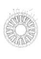
- the first member 10 and the second member 20 have two first members adjacent to each other in the circumferential direction when the movement of the second member 20 in the radial direction is restricted. It is comprised so that it may have the tensile-stress action part Z to which a tensile stress acts by engagement with the engaging part 12 and the 2nd engaging part 22.
- FIG. In the figure, the tensile stress acting part Z is shown in a darker gray than the gray showing the first tooth part 11 and the second tooth part 12. At least a part of the tensile stress acting part Z is located in a magnetic flux path from the first tooth part 11 through the stator core 1 to the second tooth part 21. In particular, in this embodiment, at least a part of the tensile stress acting part Z is located in the main magnetic flux path P.
- the main magnetic flux path P is indicated by a white arrow in the figure.
- stator core 1 At least a part of the magnetic flux from the first tooth portion 11 through the stator core 1 to the second tooth portion 21 passes through the tensile stress acting portion Z. Therefore, an increase in iron loss due to the punching strain can be mitigated by applying a tensile stress to the member having the punching strain and passing the magnetic flux therethrough.
- FIG. 9 is an axial direction view schematically showing the rotating electrical machine according to the embodiment of the present invention.
- the rotating electrical machine 4 includes a stator 2 and a rotor 5.
- the stator 2 includes a stator core 1 and a winding 3 wound around the first tooth portion 11 and the second tooth portion 21 of the stator core 1.
- the rotor 5 includes a permanent magnet portion 6 disposed so as to face the first teeth portion 11 and the second teeth portion 21 of the stator 2 with a gap Ag therebetween, and a back yoke portion 7 provided with the permanent magnet portion 6. And have.
- the permanent magnet portion 6 is provided on the back yoke portion 7 such that the permanent magnet portion 6 is positioned between the stator 2 and the back yoke portion 7 in the radial direction.
- the permanent magnet unit 6 is composed of a plurality of permanent magnets 6a arranged in a circumferential direction. The plurality of permanent magnets 6a are arranged so that magnetic poles (S poles and N poles) are alternate
- stator core 1, the stator 2, and the rotary electric machine 4 which concern on embodiment were demonstrated, this invention is not limited to the example mentioned above.
- stator core 1, the stator 2, and the rotating electrical machine 4 in the case where the radial gap rotating electrical machine is an outer rotor type rotating electrical machine have been described.
- the present invention is fixed to the inner rotor type rotating electrical machine. It can also be applied to child cores.
- first engagement portion and the second engagement portion are not limited to the example of the stator core 1.
- stator core 1 shown in FIGS. 1 to 9 is used in an outer rotor type rotating electrical machine, and the first engaging portions 12 adjacent to each other in the circumferential direction have a diameter larger than that of the second engaging portion 22. Located inside the direction.
- the two first engaging portions 12 that are going to move in the circumferential direction away from each other are engaged with the second engaging portion 22 located on the radially outer side.
- the present invention is not limited to this example, and for example, the following configuration can be adopted.
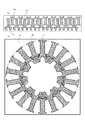
- 10 to 12 are axial direction views schematically showing a stator core according to another embodiment of the present invention partially enlarged. 10 to 12, the same reference numerals as those in FIGS. 1 to 9 are given to the components corresponding to the configuration of the stator core 1 shown in FIGS. 1 to 9.
- the 10 is used for an outer rotor type rotating electrical machine.
- the first engaging portions 12 that are adjacent to each other in the circumferential direction are positioned on the radially outer side than the second engaging portion 22.
- the two first engaging portions 12 that are going to move in the circumferential direction away from each other are engaged with the second engaging portion 22 located on the radially inner side.
- the first engagement portion 12 and the second engagement portion 22 are arranged at the circumferential contact portions 12 b and 22 b by the engagement between the first engagement portion 12 and the second engagement portion 22. And closely in the circumferential direction.
- the 1st engaging part 12 and the 2nd engaging part 22 closely_contact
- a circumferential gap Gp and a radial gap Gr are generated between the second engagement portion 22 of the second member 20 and the first member 10.
- the main magnetic flux path P extends from the first tooth portion 11 to the second tooth portion 12 through the contact surface between the first engagement portion 12 and the second engagement portion 22 in the radial contact portions 12a and 22a.
- a tensile stress acting portion Z is generated in the first member 10 and the second member 20.
- Z schematically shows the position of the tensile stress acting part.
- the main magnetic flux path P passes through the tensile stress acting part Z.
- the stator core 1 shown in FIG. 11 is used for an inner rotor type rotating electrical machine.
- the first engaging portions 12 that are adjacent to each other in the circumferential direction are positioned on the radially outer side than the second engaging portion 22.
- the two first engaging portions 12 that are about to move in the direction approaching each other in the circumferential direction are engaged with the second engaging portion 22 located on the radially inner side.
- the main magnetic flux path P extends from the first tooth portion 11 to the second tooth portion 12 through the contact surface between the first engagement portion 12 and the second engagement portion 22 in the circumferential contact portions 12b and 22b. .
- the stator core 1 shown in FIG. 12 is used for an inner rotor type rotating electrical machine.
- the first engaging portions 12 that are adjacent to each other in the circumferential direction are located on the radially inner side of the second engaging portion 22.
- the two first engaging portions 12 that are about to move in the direction approaching each other in the circumferential direction are engaged with the second engaging portion 22 located on the radially outer side.
- the first engagement portion 12 and the second engagement portion 22 are engaged in the circumferential contact portions 12 b and 22 b by the engagement of the first engagement portion 12 and the second engagement portion 22. And closely in the circumferential direction.
- the 1st engaging part 12 and the 2nd engaging part 22 closely_contact
- a circumferential gap Gp and a radial gap Gr are generated between the second engagement portion 22 of the second member 20 and the first member 10.
- the main magnetic flux path P extends from the first tooth portion 11 to the second tooth portion 12 through the contact surface between the first engagement portion 12 and the second engagement portion 22 in the radial contact portions 12a and 22a. .
- the present invention may be an outer rotor type or an inner rotor type. Further, in the present invention, when the first engagement portion and the second engagement portion are pushed toward one side from the other side in the radial direction by the base portions of the plurality of first members coming into contact with the support member, The two first engaging portions and the second engaging portions that are adjacent to each other in the circumferential direction may be engaged to limit the movement of the second member in one of the radial directions.
- the first engagement portion and the second engagement portion are not limited to the shapes shown in the embodiment. However, the present invention is preferably an outer rotor type as in the embodiment shown in FIGS. 1 to 9 and the embodiment shown in FIG.
- a tensile stress acting portion Z is generated in the first member 10 and the second member 20.
- an increase in iron loss due to punching strain is alleviated.
Landscapes
- Engineering & Computer Science (AREA)
- Power Engineering (AREA)
- Iron Core Of Rotating Electric Machines (AREA)
Abstract
La présente invention traite le problème de la fourniture d'un noyau statorique pour une machine électrique tournante ayant une structure de noyau fendu, de sorte que des complications d'un processus de fabrication puissent être évitées et que les caractéristiques de la machine électrique tournante puissent être améliorées par l'utilisation d'une structure simple. La présente invention concerne un noyau statorique pour une machine électrique tournante, le noyau statorique étant pourvu de : multiples premiers éléments ayant chacun une première section dentée qui s'étend dans une direction radialement vers l'intérieur ou une direction radialement vers l'extérieur, des premières sections de mise en prise qui sont disposés des deux côtés de la première section dentée dans une direction circonférentielle, ainsi qu'une section base qui est disposée de l'autre côté de la direction radialement vers l'intérieur ou de la direction radialement vers l'extérieur, puis qui sont disposés côte à côte dans la direction circonférentielle ; de multiples seconds éléments présentant chacun une seconde section dentée qui s'étend dans une direction radiale et une seconde section de mise en prise qui vient en prise avec deux premières sections de mise en prise circonférentiellement contiguës et qui sont disposés côte à côte dans la direction circonférentielle, de telle sorte que la seconde section dentée soit positionnée entre les deux premières sections de mise en prise contiguës ; et un élément de support qui est conçu pour venir en contact avec les sections base des multiples premiers éléments de telle manière que les sections base des multiples premiers éléments disposés côte à côte dans la direction circonférentielle soient poussées radialement dans une direction à partir de l'autre côté dans la direction radiale.
Priority Applications (1)
| Application Number | Priority Date | Filing Date | Title |
|---|---|---|---|
| EP16786166.5A EP3276792B1 (fr) | 2015-04-30 | 2016-02-03 | Noyau statorique divise et stator correspondant ou machine électrique tournante correspondante |
Applications Claiming Priority (2)
| Application Number | Priority Date | Filing Date | Title |
|---|---|---|---|
| JP2015092858A JP2018107839A (ja) | 2015-04-30 | 2015-04-30 | 回転電機用固定子コア及び固定子、並びに回転電機 |
| JP2015-092858 | 2015-04-30 |
Publications (1)
| Publication Number | Publication Date |
|---|---|
| WO2016174889A1 true WO2016174889A1 (fr) | 2016-11-03 |
Family
ID=57198640
Family Applications (1)
| Application Number | Title | Priority Date | Filing Date |
|---|---|---|---|
| PCT/JP2016/053158 Ceased WO2016174889A1 (fr) | 2015-04-30 | 2016-02-03 | Noyau statorique et stator pour machine électrique tournante et machine électrique tournante |
Country Status (4)
| Country | Link |
|---|---|
| EP (1) | EP3276792B1 (fr) |
| JP (1) | JP2018107839A (fr) |
| TW (1) | TWI584558B (fr) |
| WO (1) | WO2016174889A1 (fr) |
Cited By (1)
| Publication number | Priority date | Publication date | Assignee | Title |
|---|---|---|---|---|
| US11362551B2 (en) | 2018-11-23 | 2022-06-14 | Ford Global Technologies, Llc | Stator core of motor |
Families Citing this family (1)
| Publication number | Priority date | Publication date | Assignee | Title |
|---|---|---|---|---|
| KR102883684B1 (ko) * | 2020-11-06 | 2025-11-10 | 가부시키가이샤 티비케이 | 스테이터 및 이 스테이터를 구비하는 모터 |
Citations (2)
| Publication number | Priority date | Publication date | Assignee | Title |
|---|---|---|---|---|
| WO2006114890A1 (fr) * | 2005-04-25 | 2006-11-02 | Mitsubishi Denki Kabushiki Kaisha | Stator de moteur a rotor externe |
| JP2012075232A (ja) * | 2010-09-28 | 2012-04-12 | Aisin Aw Co Ltd | 回転電機用ステータ及びその製造方法 |
Family Cites Families (6)
| Publication number | Priority date | Publication date | Assignee | Title |
|---|---|---|---|---|
| JP2002291191A (ja) * | 2001-03-29 | 2002-10-04 | Mitsubishi Electric Corp | 固定子 |
| JP2005312119A (ja) * | 2004-04-19 | 2005-11-04 | Harmonic Drive Syst Ind Co Ltd | 分割コア式モータステータおよびその組立方法 |
| JP4706215B2 (ja) * | 2004-09-21 | 2011-06-22 | 日産自動車株式会社 | 複軸多層型回転電機のステータ構造 |
| TWI288518B (en) * | 2005-10-18 | 2007-10-11 | Hiwin Mikrosystem Corp | Core structure for motor stator |
| TW200820547A (en) * | 2006-10-16 | 2008-05-01 | Jye Maw Electric Ind Co Ltd | Core structure of motor stator |
| TWM331837U (en) * | 2007-11-23 | 2008-05-01 | Shihlin Electric & Amp Engineering Corp | Stator iron core for motor |
-
2015
- 2015-04-30 JP JP2015092858A patent/JP2018107839A/ja active Pending
-
2016
- 2016-01-27 TW TW105102556A patent/TWI584558B/zh active
- 2016-02-03 WO PCT/JP2016/053158 patent/WO2016174889A1/fr not_active Ceased
- 2016-02-03 EP EP16786166.5A patent/EP3276792B1/fr active Active
Patent Citations (2)
| Publication number | Priority date | Publication date | Assignee | Title |
|---|---|---|---|---|
| WO2006114890A1 (fr) * | 2005-04-25 | 2006-11-02 | Mitsubishi Denki Kabushiki Kaisha | Stator de moteur a rotor externe |
| JP2012075232A (ja) * | 2010-09-28 | 2012-04-12 | Aisin Aw Co Ltd | 回転電機用ステータ及びその製造方法 |
Cited By (1)
| Publication number | Priority date | Publication date | Assignee | Title |
|---|---|---|---|---|
| US11362551B2 (en) | 2018-11-23 | 2022-06-14 | Ford Global Technologies, Llc | Stator core of motor |
Also Published As
| Publication number | Publication date |
|---|---|
| EP3276792A1 (fr) | 2018-01-31 |
| JP2018107839A (ja) | 2018-07-05 |
| EP3276792B1 (fr) | 2020-06-17 |
| TWI584558B (zh) | 2017-05-21 |
| TW201639272A (zh) | 2016-11-01 |
| EP3276792A4 (fr) | 2018-04-25 |
Similar Documents
| Publication | Publication Date | Title |
|---|---|---|
| JP6627082B2 (ja) | 電動機 | |
| JP5040988B2 (ja) | ステータおよびこのステータを備えるモータ | |
| WO2016136384A1 (fr) | Induit et machine électrique tournante | |
| WO2014192076A1 (fr) | Noyau de fer de machine électrique rotative | |
| JPWO2013136485A1 (ja) | 回転電機の電機子、及び回転電機の電機子の製造方法 | |
| US20160352172A1 (en) | Stator of motor, stator unit and manufacturing method thereof | |
| JP4562093B2 (ja) | 回転電機および回転電機の製造方法 | |
| JP2012065510A (ja) | ステータ | |
| JP5988915B2 (ja) | 回転電機の積層鉄心および回転電機の積層鉄心の製造方法およびステータおよび回転電機 | |
| JP5296856B2 (ja) | ステータの製造方法 | |
| WO2016174889A1 (fr) | Noyau statorique et stator pour machine électrique tournante et machine électrique tournante | |
| JP2015061374A (ja) | ステータ | |
| JP2015144499A (ja) | 固定子鉄心の製造方法 | |
| JPWO2019235071A1 (ja) | 回転電機の固定子および回転電機 | |
| JP2018023232A (ja) | 回転電機および回転電機の製造方法 | |
| JP5515689B2 (ja) | 電機子用コア | |
| JP6327757B2 (ja) | ステータ | |
| JP6410963B2 (ja) | 回転電機 | |
| WO2012105262A1 (fr) | Stator de moteur et moteur | |
| JP5292134B2 (ja) | ステータおよびモータ | |
| JP4021433B2 (ja) | 内転型電動機の固定子 | |
| WO2011152074A1 (fr) | Noyau de machine dynamoélectrique, ainsi que machine dynamoélectrique | |
| JP7254675B2 (ja) | ブラシレスモータ及びステータ製造方法 | |
| WO2016009770A1 (fr) | Rotor | |
| JP2011166934A (ja) | 電動機 |
Legal Events
| Date | Code | Title | Description |
|---|---|---|---|
| 121 | Ep: the epo has been informed by wipo that ep was designated in this application |
Ref document number: 16786166 Country of ref document: EP Kind code of ref document: A1 |
|
| REEP | Request for entry into the european phase |
Ref document number: 2016786166 Country of ref document: EP |
|
| NENP | Non-entry into the national phase |
Ref country code: DE |
|
| NENP | Non-entry into the national phase |
Ref country code: JP |