WO2016179955A1 - Auxiliary apparatus for minimally invasive surgery and method to use the same - Google Patents
Auxiliary apparatus for minimally invasive surgery and method to use the same Download PDFInfo
- Publication number
- WO2016179955A1 WO2016179955A1 PCT/CN2015/091900 CN2015091900W WO2016179955A1 WO 2016179955 A1 WO2016179955 A1 WO 2016179955A1 CN 2015091900 W CN2015091900 W CN 2015091900W WO 2016179955 A1 WO2016179955 A1 WO 2016179955A1
- Authority
- WO
- WIPO (PCT)
- Prior art keywords
- vivo
- magnet
- magnetic field
- auxiliary apparatus
- clip
- Prior art date
- Legal status (The legal status is an assumption and is not a legal conclusion. Google has not performed a legal analysis and makes no representation as to the accuracy of the status listed.)
- Ceased
Links
Images




Classifications
-
- A—HUMAN NECESSITIES
- A61—MEDICAL OR VETERINARY SCIENCE; HYGIENE
- A61B—DIAGNOSIS; SURGERY; IDENTIFICATION
- A61B17/00—Surgical instruments, devices or methods
- A61B17/02—Surgical instruments, devices or methods for holding wounds open, e.g. retractors; Tractors
- A61B17/0218—Surgical instruments, devices or methods for holding wounds open, e.g. retractors; Tractors for minimally invasive surgery
-
- A—HUMAN NECESSITIES
- A61—MEDICAL OR VETERINARY SCIENCE; HYGIENE
- A61B—DIAGNOSIS; SURGERY; IDENTIFICATION
- A61B1/00—Instruments for performing medical examinations of the interior of cavities or tubes of the body by visual or photographical inspection, e.g. endoscopes; Illuminating arrangements therefor
- A61B1/00147—Holding or positioning arrangements
- A61B1/00158—Holding or positioning arrangements using magnetic field
-
- A—HUMAN NECESSITIES
- A61—MEDICAL OR VETERINARY SCIENCE; HYGIENE
- A61B—DIAGNOSIS; SURGERY; IDENTIFICATION
- A61B1/00—Instruments for performing medical examinations of the interior of cavities or tubes of the body by visual or photographical inspection, e.g. endoscopes; Illuminating arrangements therefor
- A61B1/04—Instruments for performing medical examinations of the interior of cavities or tubes of the body by visual or photographical inspection, e.g. endoscopes; Illuminating arrangements therefor combined with photographic or television appliances
- A61B1/041—Capsule endoscopes for imaging
-
- A—HUMAN NECESSITIES
- A61—MEDICAL OR VETERINARY SCIENCE; HYGIENE
- A61B—DIAGNOSIS; SURGERY; IDENTIFICATION
- A61B34/00—Computer-aided surgery; Manipulators or robots specially adapted for use in surgery
- A61B34/70—Manipulators specially adapted for use in surgery
- A61B34/73—Manipulators for magnetic surgery
-
- A—HUMAN NECESSITIES
- A61—MEDICAL OR VETERINARY SCIENCE; HYGIENE
- A61L—METHODS OR APPARATUS FOR STERILISING MATERIALS OR OBJECTS IN GENERAL; DISINFECTION, STERILISATION OR DEODORISATION OF AIR; CHEMICAL ASPECTS OF BANDAGES, DRESSINGS, ABSORBENT PADS OR SURGICAL ARTICLES; MATERIALS FOR BANDAGES, DRESSINGS, ABSORBENT PADS OR SURGICAL ARTICLES
- A61L31/00—Materials for other surgical articles, e.g. stents, stent-grafts, shunts, surgical drapes, guide wires, materials for adhesion prevention, occluding devices, surgical gloves, tissue fixation devices
- A61L31/02—Inorganic materials
- A61L31/022—Metals or alloys
-
- A—HUMAN NECESSITIES
- A61—MEDICAL OR VETERINARY SCIENCE; HYGIENE
- A61B—DIAGNOSIS; SURGERY; IDENTIFICATION
- A61B17/00—Surgical instruments, devices or methods
- A61B17/12—Surgical instruments, devices or methods for ligaturing or otherwise compressing tubular parts of the body, e.g. blood vessels or umbilical cord
- A61B17/122—Clamps or clips, e.g. for the umbilical cord
-
- A—HUMAN NECESSITIES
- A61—MEDICAL OR VETERINARY SCIENCE; HYGIENE
- A61B—DIAGNOSIS; SURGERY; IDENTIFICATION
- A61B17/00—Surgical instruments, devices or methods
- A61B17/00234—Surgical instruments, devices or methods for minimally invasive surgery
- A61B2017/00238—Type of minimally invasive operation
- A61B2017/00269—Type of minimally invasive operation endoscopic mucosal resection EMR
-
- A—HUMAN NECESSITIES
- A61—MEDICAL OR VETERINARY SCIENCE; HYGIENE
- A61B—DIAGNOSIS; SURGERY; IDENTIFICATION
- A61B17/00—Surgical instruments, devices or methods
- A61B2017/00477—Coupling
-
- A—HUMAN NECESSITIES
- A61—MEDICAL OR VETERINARY SCIENCE; HYGIENE
- A61B—DIAGNOSIS; SURGERY; IDENTIFICATION
- A61B17/00—Surgical instruments, devices or methods
- A61B2017/00831—Material properties
- A61B2017/00876—Material properties magnetic
Definitions
- the present disclosure relates to an auxiliary apparatus for minimally invasive surgery, and, more particularly, for the use of enlarging the visual field.
- MIS Minimally invasive surgery
- gastroscope enteroscopy
- laparoscopy laparoscopy
- thoracoscope relative tools to perform a surgery.
- the concept of minimal invasion derives from the development of the whole medical pattern and the idea of entire treatment.
- MIS focuses on the progress and recovery of patients’ psychology, sociality, physical pain, spirit and life quality. It takes care of patients and reduces their suffering.
- surgery targets are accessed through natural orifices or from one to three small incisions 0.5cm to 1cm in length, rather than through a large incision in an open surgery approach.
- the advantages of MIS over conventional surgeries include minimal scar, decreased pain, less hospital time and quick recovery. Therefore, MIS reduces damages and brings convenience to patients.
- ESD Endoscopic Submucosal Dissection
- ESD is usually used in the following diseases in a digestive tract: (1) polyps and pre-carcinoma abnormalities, especially with surgery targets > 2cm in diameter, in which ESD can completely remove abnormal tissues; (2) early cancer, especially limited to mucosa without lymph node metastasis, may be cured by ESD coupled with chromo endoscopy and ultrasonic endoscopy, which can be as effective as conventional surgery; (3) submucosal cancer, such as leiomyoma, stromal tumor, lipoma and tumors originated from mucosa and submucosa, in which ESD can dissect abnormal tissues. In Japan, almost over half of early stomach cancers and colon cancers are treated with ESD at present.
- ESD expands indications for the resections with endoscopy.
- Early cancer and pre-cancer abnormality in the gastrointestinal tract can be treated effectively due to the thorough removal of abnormal tissues by ESD.
- ESD has less trauma and is more endurable for patients. It is possible to design a personal strategy according to the site, size, shape and features of the abnormal tissues so as to retain normal tissues and functions while a tumor is completely removed.
- the visualization of the surgical field is narrowed because the surgery target on the resected mucosa moves down for gravity, which affects the performance of ESD.
- the present disclosure provides an auxiliary apparatus for MIS, including an in vivo device and an in vitro device, to maneuver a surgery target.
- the in vitro device comprises an in vitro magnetic field generating element.
- the in vivo device includes an in vivo magnet anchoring element for the surgery target.
- the in vivo magnet can move and/or rotate according to the direction change of the external magnetic field, which is induced by the in vitro magnetic field generating element, and thereby the surgery target moves in a controlled speed and/or rotates in a controlled angle according to the direction change of the external magnetic field.
- the in vitro magnetic field generating element provides a uniform magnetic field.
- the in vitro magnetic field generating element is a spherical magnet or Helmholtz coil.
- the in vitro device comprises robotic arms, and a spherical magnet, which is controlled by robotic arms to move and/or rotate in three dimensions.
- the in vivo device is further comprised of one or more magnetic cylinders, connected side by side, and each has a column shaped hollow center, a length of about 2 mm to 20 mm, an external diameter of about 1.5 mm to 10 mm, and an internal diameter from 0.3 mm to 2.4 mm.
- the length of the magnetic cylinder is from 2 mm to 3 mm with the external diameter from 1.5 mm to 2.5 mm and the internal diameter from 0.3 mm to 1.4 mm.
- the magnetic cylinder having a column shaped hollow center is longitudinally polarized.
- the in vivo magnet is comprised of odd numbered magnetic cylinders which are radially polarized and connected to each other side by side.
- the in vivo device further comprises a clip to anchor the in vivo device to the surgery target and a connector to join the clip with the in vivo magnet.
- the in vivo device comprises two clips to anchor the in vivo device to the surgery target and a connector, which joins the two clips to each side of the in vivo magnet respectively.
- the in vivo device comprises a clip to anchor the in vivo device to the surgery target, and the clip is jointed to a side of the in vivo magnet.
- the in vivo device comprises two sets of in vivo magnets, which are spaced apart, and a stiff connector to join the two sets of in vivo magnets, and the clip can take hold of the stiff connector.
- a loop is formed at an end of the connector by a tying scaffold, midshipman’s hitch or a slip knot, and the loop may encircle the clip and join the clip to the connector by pulling to reduce the diameter of the loop.
- the in vivo device comprises a holding set which houses a portion of the connector to enable the clip to take hold of the connector and in which the holding set comprises plastic tubes or silicone tubes.
- the clip is made of pure titanium or medical grade alloy.
- the in vivo magnet is made of NdFeB, Fe 3 O 4 , SmCo or AlNiCo.
- the in vivo magnet is plated with a biocompatible film of titanium, nickel or fluoride.
- the in vitro spherical magnet is a permanent magnet, made of NdFeB, Fe 3 O 4 , SmCo or AlNiCo.
- the in vivo device comprises a supporting set to integrate the in vivo magnet into an assembly;
- the supporting set comprises a base and a top cover;
- the base comprises a bed to attach with the top cover and limit the in vivo magnet from moving along a length direction of the supporting set, and a supporting column which runs from the bed to the top cover to limit the in vivo magnet to move along a radial direction of the supporting set;
- the top cover comprises a cavity to receive and fasten a distal end of the supporting column, which is distant from the bed; and a hole is disposed between the base and the top cover for the connector to pass along the length direction of the supporting set.
- the present disclosure provides a method for the controlling of the auxiliary apparatus.
- the method comprises the steps of: a) starting the in vitro magnetic field generating element to provide a magnetic field interacting with the in vivo magnet; b) controlling the change of direction of the magnetic field to manipulate the in vivo magnet which in turn makes the surgery target wrap the in vivo magnet.
- the in vitro magnetic field generating element provides a uniform magnetic field.
- the auxiliary apparatus induces rotatable a magnetic field via in vitro magnetic field generating element.
- the in vivo magnet can move and/or rotate in accordance with a direction change of an external magnetic field which is generated by the in vitro magnetic field generating element, and thereby the surgery target can move in a controlled speed and/or rotate in a controlled angle in accordance with the direction change of the said external magnetic field.
- the resected surgery target can overcome gravity to expose the visual field for dissection and improve the efficiency of resection.
- the method to control the disclosed auxiliary apparatus makes the surgery target cling to the in vivo device via the magnetic field created by the in vitro magnetic field generating element to expand the visual field.
- FIG. 1 depicts an in vitro device in accordance with the present disclosure
- FIG. 2 depicts an in vivo device in accordance with the first embodiment of the present disclosure
- FIG. 3 depicts an in vivo magnet having magnetic cylinders in accordance with the present disclosure
- FIG. 4 depicts magnetic cylinders having column shaped hollow centers which are radially polarized in accordance with the present disclosure
- FIG. 5 depicts magnetic cylinders which are longitudinally polarized in accordance with the present disclosure
- FIG. 6 depicts auxiliary tools used to facilitate the auxiliary apparatus for MIS
- FIG. 7 depicts the delivery of a clip to body cavity in accordance with the first embodiment of the present disclosure
- FIG. 8 depicts the delivery of an in vivo magnet to body cavity based on FIG. 7;
- FIG. 9 depicts the delivery of another clip to body cavity based on FIG. 8;
- FIG. 10 depicts the anchoring of an in vivo device to a surgery target based on FIG. 9;
- FIG. 11 depicts the delivery of a clip to body cavity in accordance with the second embodiment of the present disclosure
- FIG. 12 depicts the anchoring of an in vivo device to a surgery target based on FIG. 11;
- FIG. 13 depicts the anchoring of an in vivo device to a surgery target with a connective thread being cut off
- FIG. 14 depicts an in vivo device in accordance with the second embodiment
- FIG. 15 depicts a set of magnet delivered to body cavity
- FIG. 16 depicts the anchoring of an in vivo device to a surgery target via a clip
- FIG. 17 depicts an in vivo device in accordance with the third embodiment
- FIG. 18 depicts the anchoring of an in vivo device, as illustrated in FIG. 17, to a surgery target;
- FIG. 19 depicts an in vivo device received by a cannula-assisted endoscopy in accordance with the forth embodiment
- FIG. 20 depicts the delivery of an in vivo device, as illustrated in FIG. 17, to body cavity;
- FIG. 21 depicts the anchoring of an in vivo device to a surgery target in accordance with the fourth embodiment
- FIG. 22 depicts the anchoring of an in vivo device to a surgery target in accordance with the fifth embodiment
- FIG. 23 depicts Helmholtz coil presenting a uniform magnetic field
- FIG. 24 depicts in vivo magnets which are integrated to an assembly by a supporting set
- FIG. 25 depicts a section view of FIG. 24 along the A-A direction.
- FIG. 26 depicts the steps by which a connector forms a loop by tying scaffold knot and joins to a clip
- FIG. 27 depicts the steps by which a connector forms a loop by tying a midshipman’s hitch and joins to a clip
- FIG. 28 depicts the steps by which a connector forms a loop by tying a slip knot and joints to a clip.
- FIG. 1 to FIG. 25 schematically depict that the disclosed auxiliary apparatus (unlabeled) , which is adapted to MIS such as ESD and endoscopic mucosal resection (EMR) , results in enlargement of the visual field of a surgery via stretching the surgery target 3.
- MIS such as ESD and endoscopic mucosal resection
- EMR endoscopic mucosal resection
- the operator makes an incision on the mucous membrane at an end of the surgery target 3.
- the said auxiliary apparatus is then anchored on the resected mucous membrane and stretches the surgery target 3 to separate it from the mucous membrane or muscles, causing enlargement of the visual field and improvement of performance.
- the said auxiliary apparatus for MIS includes an in vivo device 1 which is mounted inside the body cavity, in use, to fix a surgery target, and an in vitro device 2 to control the mobility of the in vivo device 1.
- the in vivo device 1 takes hold of the surgery target 3, followed with moving or rolling driven by the in vitro device 2, and results in the resected or dissected surgery target 3 to overcome gravity, causing exposure of the visual field in surgery.
- the in vitro device 2 functions as an in vivo magnet 11 with limited effect on the ferromagnetic material endoscope. Magnetic force is typically hard to eliminate in the foregoing effect.
- the in vivo magnet 11 is adjacent to the endoscope. Usually, if the magnetic force on an endoscope is weak, it is the same on the in vivo magnet 11.
- the in vitro device 2 includes a magnetic field generating element outside the body, which provides a rotatable magnetic field.
- the in vivo device 1 includes an in vivo magnet 11 which may anchor to the surgery target 3.
- the in vivo magnet 11 is able to move and/or rotate due to the direction change of the external magnetic field, which is induced by the magnetic field generating element outside the body. Accordingly, the surgery target 3 moves in a controlled speed and/or rotates in a controlled angle to wrap the in vivo device 1.
- the in vitro device 2 includes a magnetic field generating element outside the body, which provides a uniform magnetic field.
- the uniform magnetic field refers to that with small absolute value of the gradient magnetic field, which is suitable for the present disclosure but not specifically referring to an absolutely uniform magnetic field.
- the uniform magnetic field can be a uniform magnetic field, approximate uniform magnetic field, and uniform magnetic field in a portion of the space. The smaller the absolute value of the gradient magnetic field is, the more applicable the uniform magnetic field is for the execution of the present disclosure. Alternatively, the absolute value of the gradient magnetic field is less than 4 Gs/mm. Furthermore, the absolute value of the gradient magnetic field is less than 2 Gs/mm.
- ⁇ magnetoconductivity.
- B is external field.
- a is a factor for shape. For a sphere, the factor “a” doesn’ t change with angle. For other shapes, the factor “a” is variable according to angle.
- the magnet torque interacting with soft magnetic materials is zero.
- the uniform external magnetic field may drive the in vivo magnet 11 to move and/or rotate via the magnet torque. Accordingly, the resected or dissected surgery target 3 overcomes gravity and gets curling to wrap the in vivo device 1 to expose the visual field for resection without effect to the endoscope.
- Helmholtz coil For an example of a Helmholtz coil, three pairs of Helmholtz coils are placed vertically. Each pair of Helmholtz coils is exerted with the same current to generate a relatively uniform magnetic field in the center.
- the diameters of Helmholtz coils in three dimensions are from 300mm to 1000mm, with the same coil constant. Adapted to the uniform magnetic field in three dimensions, the field intensity is from 10Gs to 2000Gs.
- N is the number of coils.
- I is current (unit: A) .
- B is field intensity (unit: T) .
- a is radius (unit: m) . The distance of each pair of coils is equal to its radius.
- Three pairs of coils provide the magnetic fields in three directions B x , B y , B z ,
- the general field intensity is B.
- the magnetic field B rotates at angular velocity w on the surface with in the normal direction.
- the torque exerted by the magnetic field B may drive the rotation of the in vivo magnet 11 which is fixed on the surface of the abnormal mucosa to uncover. Since the direction of rotation is able to change randomly, ⁇ and the direction angle of is also the functions of time ⁇ (t) , The direction to uncover the mucosa is able to be adjusted through ⁇ (t) and
- the spherical magnet which has the best uniformity among all shapes of permanent magnets, may be used to provide the uniform rotatable magnetic field.
- the spherical magnet has a dipole magnetic field with some certain of gradient magnetic field, which is called nonuniform.
- M is proportional to the volume of the spherical magnet, therefore
- R is the radius of the spherical magnet.
- the magnetic field performs better in uniformity for a spherical magnet with longer radius. Thereby, when the magnetic field is the same, the magnetic field of a big spherical magnet is better in uniformity than that of a small one.
- FIG. 23 schematically depicts the uniform magnetic field provided by the Helmholtz coil.
- the in vitro device 2 includes a motor (not shown) , a plurality of three-axis robot arms 22 driven by the motor, and a spherical magnet 21 controlled by the robot arms 22 to move and/or rotate in three dimensions outside the body.
- the three-axis robot arms 22 can be any machinery that may hold the spherical magnet 21 and drive it to move and/or rotate in three dimensions outside body. Structure for the robot arm 22 is not limited to this embodiment.
- the details about how the in vitro device 2 controls the spherical magnet 21 to move and/or rotate in three dimensions refer to the Chinese patent CN201310136094.0.
- the spherical magnet 21 is constructed of various materials, including for example, NdFeB, Fe 3 O 4 , SmCo or AlNiCo.
- the dissected mucous membrane may overcome gravity to expose visual field during a MIS procedure through the change of distance between the spherical magnet 21 and the in vivo magnet 11 as well as the movement and/or rotation of the spherical magnet 21. Accordingly, the efficiency and accuracy of resection is improved.
- the in vivo device 1 includes an in vivo magnet 11 matching with the spherical magnet 21, at least a clip 12 for the fixation of the in vivo device 1 and the surgery target 3, a connector 13 joining the clip 12 with the in vivo magnet 11, at least a holding set 14 housing a portion of the connector 13 for the grip of the clip 12, and a supporting set15 integrating the in vivo magnet 11 into an assembly.
- the clip 12 is made of medical grade titanium and is used to take hold of the surgery target 3.
- the medical grade titanium can be pure titanium or an alloy.
- the in vivo magnet 11 is a permanent magnet made of NdFeB, Fe 3 O 4 , SmCo or AlNiCo.
- the surface of the in vivo magnet 11 is plated with biocompatible film, which is in a complex structure of one or more film (s) of titanium, nickel, fluoride, Pairuolin or diamond-like carbon.
- the fluoride is polytetrafluoroethylene (PTFE) .
- an end of the connector 13 comprises a loop made in the manner of a scaffold, midshipman’s hitch or slip knot.
- the loop includes a drawing member that may adjust the diameter of the loop.
- the loop encircles the clip 12, in use, and then is collapsed by pulling the drawing member to join the clip 12 to the connector 13.
- the joint means can be any means that would adapt to the linkage of the clip 12 and connector 13, and are not limited to the illustrations in FIG. 26-FIG. 28.
- the connector 13 can be a soft or rigid connective thread.
- the holding set 14 is a tube, which is longer in diameter than the connective thread and made of soft plastic or silicone.
- the clip 12 grips the surgery target 3 and the holding set 14, in use, resulting in the stable fixation of the surgery target 3 and the in vivo device 1.
- the in vivo magnet 11 is made of one or more magnetic cylinders each having a hollow column-shaped center. Stung by the connector 13, the magnetic cylinders are connected side by side via magnetic power. The self-arrangement of the magnetic cylinders inside the body forms the in vivo magnet 11 and thus reduces the requirement for the diameter of the orifices.
- the length of each magnetic cylinder is from 2mm to 3 mm with the external diameter from 1.5mm to 2.5mm and the internal diameter from 0.3mm to 1.4mm.
- the number of magnetic cylinders is determined by the size of the surgery target 3. The bigger the surgery target 3, the more the magnetic cylinders, and vice versa.
- FIG. 24 and 25 schematically illustrate the supporting set 15, in the shape of a column, which includes a base 151 and a top cover 152 which are made of PC.
- the base 151 comprises a bed 1511 and a supporting column 1512.
- the bed 1511 matches with the top cover 152 to limit the in vivo magnet 11 moving along the length direction of the supporting set 15.
- the supporting column 1512 runs from the bed 1511 to the top cover 152 to limit the in vivo magnet 11 moving along the radial direction of the supporting set 15.
- the fixing end (unlabeled) is disposed at the distal end of the supporting column 1512, which is distant from the bed 1511.
- the diameter of the fixing end is shorter than that of the supporting column 1512.
- the diameter of the supporting column 1512 is shorter than that of the bed 1511.
- the base 151 and the top cover 152 are uncovered, in use, and the supporting column 1512 is housed by the magnetic cylinders having hollow column-shaped centers. And then, the top cover 152 engages to the distal end of the supporting column 1512, which is distant from the bed 1511. Thereby, the in vivo magnet 11 is integrated by the supporting set 15. After that, the connective thread passes through the hole 153 to engage with the clip 12 to form an assembly.
- One of the advantages using the supporting set 15 is to enlarge the internal diameter of the magnetic cylinders having hollow column-shaped centers while the diameter of the connective thread is fixed, which facilitates the internal coating of the magnetic cylinders having hollow column-shaped centers. If a plurality of magnetic cylinders having hollow column-shaped centers is applied, the cylinders are held by the base 151 and the top cover 152 prevent them from falling apart.
- the in vivo device 1 includes two clips 12 fastening the in vivo device 1 and the surgery target 3, a connector 13 guiding the clips 12 to either side of the in vivo magnet 11 respectively and attaching the clips 12 to a side of the in vivo magnet 11.
- the tubes are made of soft plastic or silicone and are disposed at a side of the in vivo magnet 11.
- the column-shaped magnetic cylinders are longitudinally polarized, and the polarization directions for all cylinders are identical.
- the magnetic cylinders having hollow column-shaped centers can be radially polarized.
- odd numbered, column-shaped magnetic cylinders, strung by the connective thread are connected to each other side by side via the magnetic power to form the in vivo magnet 11.
- the adjacent magnetic cylinders are opposite in polarization direction.
- FIG. 1 to FIG. 13 illustrates preferable embodiments.
- the auxiliary apparatus for MIS includes an in vivo device 1 and an in vitro device 2.
- the in vivo device 1 comprises hollow in vivo magnets 11, two clips 12, a connective thread and a holding set 14.
- FIG. 3 illustrates the length of the in vivo magnet 11 which is adjustable in accordance with the size of the surgery target 3 during an ESD procedure.
- the in vivo magnet 11 is made of one magnetic cylinder having hollow column-shaped centers (depicted in a) .
- the in vivo magnet 11 is made of two magnetic cylinders connected side by side (depicted in b) . If the surgery target 3 is large, the in vivo magnet 11 is made of three or more magnetic cylinders (depicted in c) . The number of magnetic cylinders is adjustable in accordance with the size of the surgery target 3 instead of being restricted to set number.
- FIG. 4 illustrates that the in vivo magnet 11 consists of odd numbered magnetic cylinders when the magnetic cylinders having hollow column shaped hollow centers are uniformly radially polarized. The adjacent magnetic cylinders are opposite in polarization direction.
- FIG. 5 illustrates that magnetic cylinders having hollow column-shaped centers are uniformly longitudinally polarized.
- the magnetic cylinders are plated with a biocompatible film, which uses materials such as titanium, nickel or fluoride.
- the clip 12 is made of pure titanium or titanium alloy. Preferably, the number of the clips 12 is two. Two clips 12 and the in vivo magnet 11 are jointed by the connective thread when in use.
- FIG. 6 schematically illustrates some auxiliary tools applied in MIS which include a cannula-assisted endoscope 31, a guide wire 32 and a titanium clip releaser 33.
- the cannula-assisted endoscope 31 delivers the in vivo device 1, such as the in vivo magnet 11, the clip 12, the connective thread and the holding set 14, into the body cavity.
- the guide wire 32 facilitates the cannula-assisted endoscope 31 to deliver the in vivo magnet 11 and holding set 14.
- the titanium clip releaser 33 dismisses the clip 12.
- the in vivo magnet 11 can be integrated into an assembly by the supporting set 15.
- FIG. 8 schematically illustrates the in vivo magnet 11 and the holding set 14 being introduced into the body cavity.
- the cannula-assisted endoscope 31 sequentially disposes the in vivo magnet 11, which is constructed of three magnetic cylinders having hollow column-shaped centers, and a soft plastic tube on the connective thread, and positions them via the connective thread to the side of the first clip 12.
- the connective thread is parallel with the incision of the surgery target 3.
- Three magnetic cylinders having hollow column-shaped centers are uniformly radially polarized as depicted in FIG. 4.
- the cannula-assisted endoscope 31 delivers the second clip 12 near to the soft plastic tubes.
- the second clip 12 takes hold of the soft plastic tubes and anchors at the resected mucous membrane.
- the length direction of the in vivo magnet 11 is parallel with the incision.
- the connective thread at the distal end of the plastic tube that is distant from the in vivo magnet 11, is cut off to integrate two clips 12, the in vivo magnet 11 and the soft plastic tube into a unit which anchors to the recision of the surgery target 3 via two clips 12.
- the cannula-assisted endoscope 31 moves far away from the in vivo magnet 11 to perform further operation.
- Two clips 12 and the in vivo magnet 11 are integrated via the connective thread.
- the in vivo magnet 11 driven by the magnetic force may control two clips 12 to manipulate the surgery targets 3 on the anchored mucous membrane to activate accordingly.
- the spherical magnet 21 controls clips 12 and the in vivo magnet 11 to overcome gravity. Thereby the visualization of surgical field is clarified and the surgery can be performed smoothly.
- the in vivo magnet 11 can be held by the supporting set 15 before it is delivered to the body cavity.
- Two clips are respectively disposed at the external sides of the bed 1511 and the top cover 152. More specifically, uncovering the base 151 and the top cover 152, surrounding the supporting column 1512 with the magnetic cylinders having hollow column-shaped centers, and engaging the top cover 152 to the supporting column 1512 results in the integration of the in vivo magnet 11 by the supporting set 15. And then the connective thread passes through the hole 153 to introduce the in vivo magnet 11. In this process, a plurality of magnetic cylinders having hollow column-shaped centers is held by the base 151 and the top cover 152 prevent them from falling apart.
- FIG. 11 to FIG. 12 schematically illustrate the operation process of the present disclosed auxiliary apparatus, which is uniformly longitudinally polarized.
- the clip 12 and the connective thread are delivered to the appropriate site on the resected mucous membrane by the cannula-assisted endoscope 31.
- the in vivo magnet 11 and the holding set 14 are delivered into the body cavity.
- the cannula-assisted endoscope 31 sequentially threads the in vivo magnet 11, which is constructed of four magnetic cylinders having hollow column-shaped centers, and a silicone tube on the connective thread, and then positions them to one side of the first clip 12 via the connective thread.
- the connective thread is perpendicular to the incision of the surgery target 3.
- Four magnetic cylinders having hollow column-shaped centers are uniformly longitudinally polarized as depicted in FIG. 5.
- the cannula-assisted endoscope 31 positions the second clip 12 near to the silicone tube.
- the second clip 12 takes hold of the tube, and anchors to the surgery targets 3 on the mucous membrane with appropriate spacing to the incision, and then is dismissed from the cannula-assisted endoscope 31.
- the connective thread at the distal end of the plastic tube that is distant form the in vivo magnet 11, is cut off to make two clips 12, the in vivo magnet 11 and the silicone tube to be integrated into an assembly which is anchored to the surgery target 3 through two clips 12. And then the cannula-assisted endoscope 31 moves far away from the in vivo magnet 11 to perform further operation.
- the first clip 12 may anchor to the surgery targets 3 on the mucous membrane with appropriate spacing to the incision. And then the in vivo magnet 11 and the tube are delivered near to the first clip 12, and the second clip 12 is positioned at the incision. Meanwhile, the in vivo magnet 11, before being delivered into body cavity, can by held into an assembly via the supporting set 15. The operation is similar in manner with the first embodiment and will not be described here.
- Two clips 12 and the in vivo magnet 11 are integrated into a unit through the connective thread.
- the in vivo magnet 11, driven by the magnetic force may manipulate two clips 12 to control the anchored surgery targets 3 on the mucous membrane to activate accordingly.
- the in vitro magnet 21 rotates
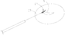
- the in vivo magnet 11 rotates together to bend the surgery target 3, resulting in wrapping of the surgery target 3 on the surface of the in vivo magnet 11. Thereby, visualization of the surgical field is expanded.
- the connector 13 joints the in vivo magnet 11 and the clip 12, and guides their delivery.
- the present disclosure makes the surgery target 3 on the resected mucous membrane overcome gravity by controlling the in vivo magnet 11 via the in vitro magnetic field in ESD, resulting in the exposure of the visual field for the dissection and the improvement of the resection efficiency.
- the in vivo device 1 includes two sets of in vivo magnets 11 which are spaced apart and jointed by the connector 13.
- the clip 12, which is positioned between two sets of the in vivo magnets 11, is also linked to the connector 13.
- the connector 13 is stiff to allow two sets of in vivo magnets 11 to conquer the magnetic power and thereby be set apart.
- the holding set 14, comprised of soft plastic or silicone tube houses a portion of the connector 13 between two sets of in vivo magnets 11. Thereby, two sets of in vivo magnets 11, stiff connector 13, and the holding set 14 are joined to a magnetic composition via stiff connector 13 in use. Meanwhile, the clip 12 takes hold of the holding set 14 and the surgery target 3 so as to anchor the in vivo device 1 to the surgery target 3.
- stiff connector 13 may prevent one of the two sets of in vivo magnets 11 from rolling-over by the magnetic force of attraction for each other.
- Each set of the in vivo magnets 11 may comprise one or more magnetic cylinders.
- each set of in vivo magnet 11 may couple with a supporting set 15 respectively, or, two sets of in vivo magnet 11 share a supporting set 15.
- stiff connector 13 is pipe-shape to enclose the supporting column 1512.
- the first knot is tied at one end of the stiff connector 13. Then the stiff connector 13 sequentially passes through the first set of the in vivo magnet 11, the holding set 14 and the second set of the in vivo magnet 11. The second knot is tied at the other end of the stiff connector 13, close to the second set of the in vivo magnet 11.
- the sizes of the first and second knots match with the internal diameter of the in vivo magnets 11 to assemble two sets of the in vivo magnets 11 and the holding set 14 into an assembly.
- each set of the in vivo magnet 11 may couple with a supporting set 15 to form individual assembly.
- the stiff connector may be set in shape of cylinder, which can sequentially assist the first set of the in vivo magnets 11, the holding set 14 and the second set of the in vivo magnet11 to house the supporting column 1512. In this instance, only one supporting set 15 is needed.
- the cannula-assisted endoscope 31 delivers sets of the in vivo magnet 11, which is threaded to the soft connective thread, to the incision on the mucous membrane.
- the cannula-assisted endoscope 31 positions the clip 12 to the incision via the soft connective thread and adjusts the delivered items to appropriate sites.
- the clip 12 is released to take hold of the holding set 14 and the incision of surgery target 3.
- the connective thread is cut off at the distal end of the second knot that is far away from the in vivo magnet 11 to integrate the clip 12 and the in vivo magnets 11 into an assembly being anchored to the surgery target 3 via the clip 12.
- the spherical magnet 21 drives the in vivo magnet 11 to manipulate the in vivo device 1, resulting in the resected surgery target 3 to overcome gravity and expose the visual field for dissection.
- the connector 13 is different from the soft connective thread, which guides and delivers the in vivo magnet 11 and the clip 12.
- FIG. 17 and FIG. 18 schematically illustrate the third embodiment, which is different from the first embodiment in that the in vivo device 1 includes the clip 12 which anchors the in vivo device 1 to the surgery target3.
- the clip 12 connects to side of the in vivo magnet 11.
- the connector 13 is soft connective thread.
- a knot is tied at one end of the soft connector.
- the other end passes through the in vivo magnet 11 and then forms a loop by tying a scaffold, midshipman’s hitch or slipknot.
- the loop, which may encircle the clip 12 includes a drawing member which is a portion of the thread forming the loop.
- the drawing member is used to adjust the diameter of the loop.
- the loop is collapsed by pulling the drawing member to joint the clip 12 to the connector 13, resulting in the assembly of the in vivo magnet 11 and the clip 12.
- the cannula-assisted endoscope 31, the guide wire 32 and the titanium clip releaser 33 deliver the in vivo magnet 11 and the clip 12 near to the incision and then release the clip 12 to grip the edge of the incision.
- the in vivo magnet 11 and the clip 12 form an assembly via the soft connective thread.
- the in vitro magnet 11 driven by the magnetic force, activates accordingly to manipulate the clip 12.
- the surgery target 3 is small in size
- the in vitro magnet 21 moves to drive the in vivo magnet 11 and correspondingly control the clip 12 to grasp and retract the surgery target 3 to increase the visualization of surgery.
- the surgery target 3 is large, besides the above method, the in vitro magnet 21 may rotate to drive the in vivo magnet 11 and accordingly make the surgery target 3 wrapped at the surface of the in vivo magnet 11 to gradually expand the visual field.
- the in vivo magnet 11 comprises a guide mean 111 at the side close to the clip 12.
- the diameter of the guide mean 111 matches with the internal diameter of the titanium clip releaser 33. Therefore, it is convenient to harbor the in vivo magnet 11to the titanium clip releaser 33 for delivery.
- the volume of the in vivo magnet 11 is bigger and the clip 12 is in shape of hook.
- the in vivo magnet 11 consists of one or two magnetic cylinders having hollow column-shaped centers, which are connected to each other side by side.
- the length of the magnetic cylinder is from 2mm to 20 mm with the external diameter from 1.5mm to10mm and the internal diameter from 0.3mm to 2.4mm.
- the in vivo magnet 11, illustrated in this embodiment, is applicable for laparotomy, which punctures a channel on the abdominal cavity and delivers the in vivo device 1 to the surgery target 3 via the channel with the assistance of auxiliary tools.
- the present disclosure anchors the clip 12 to the surgery target 3 and manipulates the in vivo device 1 through the in vitro magnetic field generating device to make the resected surgery target 3 overcome gravity to expose the visual field of surgery.
- the method to control the disclosed auxiliary apparatus makes the surgery target 3 wrap the in vivo device 1 via the uniform magnetic field created by the in vitro magnetic field generating device to expand the visual field.
Landscapes
- Health & Medical Sciences (AREA)
- Life Sciences & Earth Sciences (AREA)
- Surgery (AREA)
- Engineering & Computer Science (AREA)
- General Health & Medical Sciences (AREA)
- Heart & Thoracic Surgery (AREA)
- Animal Behavior & Ethology (AREA)
- Public Health (AREA)
- Veterinary Medicine (AREA)
- Medical Informatics (AREA)
- Biomedical Technology (AREA)
- Molecular Biology (AREA)
- Nuclear Medicine, Radiotherapy & Molecular Imaging (AREA)
- Physics & Mathematics (AREA)
- Biophysics (AREA)
- Optics & Photonics (AREA)
- Pathology (AREA)
- Radiology & Medical Imaging (AREA)
- Robotics (AREA)
- Vascular Medicine (AREA)
- Epidemiology (AREA)
- Inorganic Chemistry (AREA)
- Chemical & Material Sciences (AREA)
- Reproductive Health (AREA)
- Surgical Instruments (AREA)
- Endoscopes (AREA)
Priority Applications (4)
| Application Number | Priority Date | Filing Date | Title |
|---|---|---|---|
| KR1020177035941A KR102121104B1 (ko) | 2015-05-14 | 2015-10-14 | 최소 침습 미세 수술에 이용되는 보조 장치 및 그 제어 방법 |
| JP2018511306A JP6546342B2 (ja) | 2015-05-14 | 2015-10-14 | 最小侵襲手術に用いられる補助装置およびその制御方法 |
| EP15891655.1A EP3294147B1 (de) | 2015-05-14 | 2015-10-14 | Hilfsvorrichtung für minimalinvasive chirurgie |
| ES15891655T ES2973369T3 (es) | 2015-05-14 | 2015-10-14 | Aparato auxiliar para cirugía mínimamente invasiva |
Applications Claiming Priority (4)
| Application Number | Priority Date | Filing Date | Title |
|---|---|---|---|
| CN201510246170.2 | 2015-05-14 | ||
| CN201510246170 | 2015-05-14 | ||
| CN201510477005.8 | 2015-08-06 | ||
| CN201510477005 | 2015-08-06 |
Publications (1)
| Publication Number | Publication Date |
|---|---|
| WO2016179955A1 true WO2016179955A1 (en) | 2016-11-17 |
Family
ID=54711092
Family Applications (1)
| Application Number | Title | Priority Date | Filing Date |
|---|---|---|---|
| PCT/CN2015/091900 Ceased WO2016179955A1 (en) | 2015-05-14 | 2015-10-14 | Auxiliary apparatus for minimally invasive surgery and method to use the same |
Country Status (7)
| Country | Link |
|---|---|
| US (2) | US10070854B2 (de) |
| EP (1) | EP3294147B1 (de) |
| JP (1) | JP6546342B2 (de) |
| KR (1) | KR102121104B1 (de) |
| CN (1) | CN105125245B (de) |
| ES (1) | ES2973369T3 (de) |
| WO (1) | WO2016179955A1 (de) |
Families Citing this family (38)
| Publication number | Priority date | Publication date | Assignee | Title |
|---|---|---|---|---|
| US10151606B1 (en) | 2016-02-24 | 2018-12-11 | Ommo Technologies, Inc. | Tracking position and movement using a magnetic field |
| US11504024B2 (en) | 2018-03-30 | 2022-11-22 | Vibrant Ltd. | Gastrointestinal treatment system including a vibrating capsule, and method of use thereof |
| GB2554354B (en) | 2016-09-21 | 2021-06-02 | Vibrant Ltd | Systems for adaptive treatment of disorders in the gastrointestinal tract |
| US10905378B1 (en) | 2017-01-30 | 2021-02-02 | Vibrant Ltd | Method for treating gastroparesis using a vibrating ingestible capsule |
| US10888277B1 (en) | 2017-01-30 | 2021-01-12 | Vibrant Ltd | Method for treating diarrhea and reducing Bristol stool scores using a vibrating ingestible capsule |
| CN107411794A (zh) * | 2017-09-04 | 2017-12-01 | 上海市同济医院 | 可辅助内镜下闭合规则粘膜创面的磁力系统 |
| US11033278B2 (en) | 2017-11-08 | 2021-06-15 | Mayo Foundation For Medical Education And Research | Systems and methods for endoscopic submucosal dissection using magnetically attachable clips |
| US11350946B2 (en) * | 2017-11-08 | 2022-06-07 | Mayo Foundation For Medical Education And Research | Systems and methods for endoscopic submucosal dissection using magnetically attachable clips |
| CN111820995A (zh) * | 2017-11-10 | 2020-10-27 | 西安交通大学医学院第一附属医院 | 一种辅助内镜下粘膜剥离手术的装置 |
| EP3773407B1 (de) | 2018-03-30 | 2025-08-27 | Vibrant Ltd. | Gastrointestinales behandlungssystem mit einer vibrierenden kapsel und verfahren zu dessen verwendung |
| US10537720B2 (en) | 2018-04-09 | 2020-01-21 | Vibrant Ltd. | Method of enhancing absorption of ingested medicaments for treatment of parkinsonism |
| US12083303B2 (en) | 2019-01-21 | 2024-09-10 | Vibrant Ltd. | Device and method for delivering a flowable ingestible medicament into the gastrointestinal tract of a user |
| US11638678B1 (en) | 2018-04-09 | 2023-05-02 | Vibrant Ltd. | Vibrating capsule system and treatment method |
| US11510590B1 (en) | 2018-05-07 | 2022-11-29 | Vibrant Ltd. | Methods and systems for treating gastrointestinal disorders |
| CN110809425B (zh) * | 2018-06-02 | 2022-05-27 | 上海安翰医疗技术有限公司 | 胶囊内窥镜控制设备 |
| CN109223073B (zh) * | 2018-11-23 | 2024-07-02 | 上海安翰医疗技术有限公司 | 磁性辅助件及具有磁性辅助件的微创手术辅助装置 |
| CN109288549B (zh) * | 2018-11-27 | 2021-03-16 | 上海安翰医疗技术有限公司 | 微创手术辅助装置及其控制方法 |
| AU2020205162B2 (en) | 2019-01-03 | 2025-06-05 | Vibrant Ltd. | Device and method for delivering an ingestible medicament into the gastrointestinal tract of a user |
| US11737679B2 (en) | 2019-01-08 | 2023-08-29 | Covidien Lp | Localization systems and methods of use |
| US11690679B2 (en) | 2019-01-08 | 2023-07-04 | Covidien Lp | Localization systems and methods of use |
| GB201900780D0 (en) | 2019-01-21 | 2019-03-06 | Vibrant Ltd | Device and method for delivering a flowable ingestible medicament into the gastrointestinal tract of a user |
| GB201901470D0 (en) | 2019-02-04 | 2019-03-27 | Vibrant Ltd | Vibrating capsule for gastrointestinal treatment, and method of use thereof |
| CN114072039B (zh) | 2019-04-09 | 2025-08-29 | 安克斯机器人公司 | 取液释药系统及方法 |
| USD1060669S1 (en) | 2019-04-09 | 2025-02-04 | AnX Robotica Corp | Tether for a capsule endoscope |
| CN112336295B (zh) * | 2019-08-08 | 2024-07-05 | 上海安翰医疗技术有限公司 | 磁性胶囊内窥镜的控制方法、装置、存储介质、电子装置 |
| CN211355355U (zh) * | 2019-08-08 | 2020-08-28 | 上海安翰医疗技术有限公司 | 一种磁性胶囊内窥镜的远程控制系统 |
| US11089946B2 (en) | 2019-10-07 | 2021-08-17 | Anx Robotica Corp. | Inflatable in-vivo capsule endoscope with magnetic guide |
| CN211460328U (zh) * | 2019-12-20 | 2020-09-11 | 深圳市资福医疗技术有限公司 | 一种用于微创手术的床下式磁控设备 |
| CN110897663B (zh) * | 2019-12-20 | 2025-10-24 | 深圳市资福医疗技术有限公司 | 一种微创手术的辅助装置 |
| CN111297421A (zh) * | 2020-03-30 | 2020-06-19 | 西安交通大学医学院第一附属医院 | 一种用于内镜下黏膜剥离术的磁锚定装置及其使用方法 |
| EP4181799A1 (de) * | 2020-07-16 | 2023-05-24 | Covidien LP | Magnetisch anbringbare gewebeclips zur verwendung bei der endoskopischen submukosalen dissektion |
| CN111808916A (zh) | 2020-07-24 | 2020-10-23 | 上海安翰医疗技术有限公司 | 胰蛋白酶检测薄膜及其制备方法、应用和胰蛋白酶检测试剂盒 |
| CN112043325B (zh) * | 2020-10-12 | 2021-10-01 | 天津市人民医院 | 一种体腔手术用磁力拉件及工作方法 |
| CN112674887B (zh) * | 2020-11-27 | 2021-12-07 | 中国人民解放军总医院第五医学中心 | 一种用于放疗所引起黏膜反应的辅助清理装置 |
| US11700437B2 (en) | 2020-12-16 | 2023-07-11 | Anx Robotica Corp. | Capsule endoscope with a dynamic adjustable color illumination spectrum |
| US11839440B2 (en) | 2021-07-30 | 2023-12-12 | Corindus, Inc. | Attachment for robotic medical system |
| CN113425347B (zh) * | 2021-08-25 | 2021-12-31 | 深圳市资福医疗技术有限公司 | 一种输送结构及应用其的esd磁锚定夹 |
| CN113712669B (zh) * | 2021-09-02 | 2023-11-07 | 浙江大学 | 一种三维无线磁性机器人及控制方法 |
Citations (8)
| Publication number | Priority date | Publication date | Assignee | Title |
|---|---|---|---|---|
| US20040050395A1 (en) | 2002-09-13 | 2004-03-18 | Pentax Corporation | Magnetic anchor remote guidance system |
| US20070135678A1 (en) | 2005-12-14 | 2007-06-14 | Olympus Medical Systems Corp. | Lifting method for lesion area, and anchoring device |
| US20090043246A1 (en) | 2007-08-07 | 2009-02-12 | Dominguez Guillermo Manuel | Magnetic Surgical Device to Manipulate Tissue in Laparoscopic Surgeries Performed with a Single Trocar or Via Natural Orifices |
| WO2011023622A1 (de) * | 2009-08-24 | 2011-03-03 | Siemens Aktiengesellschaft | Verfahren zum betreiben eines endoskopiesystems |
| CN102247179A (zh) | 2011-04-11 | 2011-11-23 | 西安交通大学 | 一种用于消化内镜手术的磁性辅助牵拉装置 |
| CN102743174A (zh) * | 2012-06-30 | 2012-10-24 | 安翰光电技术(武汉)有限公司 | 一种控制胶囊或探针运动的方法 |
| CN103156568A (zh) * | 2012-08-22 | 2013-06-19 | 武汉安康通光电技术有限公司 | 一种可释放和可磁控的细线管胶囊食道内窥镜 |
| US20150018614A1 (en) | 2013-04-18 | 2015-01-15 | ANKON TECHNOLOGIES Co., INC | Apparatus and method for controlling movement of a capsule endoscope in digestive tract of a human body |
Family Cites Families (31)
| Publication number | Priority date | Publication date | Assignee | Title |
|---|---|---|---|---|
| GB9109166D0 (en) | 1991-04-27 | 1991-06-12 | Byrne Phillip O | Method of concentrating bacteria and devices employing that method |
| US5337472A (en) * | 1993-05-26 | 1994-08-16 | The United States Of America As Represented By The Secretary Of The Army | Method of making cylindrical and spherical permanent magnet structures |
| US5704939A (en) * | 1996-04-09 | 1998-01-06 | Justin; Daniel F. | Intramedullary skeletal distractor and method |
| JP4320202B2 (ja) * | 2003-04-11 | 2009-08-26 | Hoya株式会社 | 内視鏡用アンカー遠隔誘導システム及び内視鏡用誘導装置 |
| JP4360835B2 (ja) * | 2003-06-03 | 2009-11-11 | Hoya株式会社 | 内視鏡用把持装置及び磁気アンカー遠隔誘導システム |
| JP4373715B2 (ja) * | 2003-06-04 | 2009-11-25 | Hoya株式会社 | 内視鏡用把持装置及びアンカー遠隔誘導システム |
| KR100615881B1 (ko) * | 2004-06-21 | 2006-08-25 | 한국과학기술연구원 | 캡슐형 내시경 조종 시스템 |
| US7285087B2 (en) * | 2004-07-15 | 2007-10-23 | Micardia Corporation | Shape memory devices and methods for reshaping heart anatomy |
| JP4681920B2 (ja) * | 2005-03-30 | 2011-05-11 | オリンパスメディカルシステムズ株式会社 | 体腔内に留置される留置具 |
| EP1915099A2 (de) * | 2005-08-01 | 2008-04-30 | Orthogon Technologies 2003 Ltd. | Implantierbares magnetisch aktiviertes stellglied |
| EP1797823B1 (de) * | 2005-12-13 | 2010-03-03 | University of Dundee | Medizinisches Instrument zum Manipulieren, insbesondere zum Zurückziehen des Gewebes oder des Organes. |
| US20070156028A1 (en) * | 2005-12-29 | 2007-07-05 | Van Lue Stephen J | Magnetic surgical/oral retractor |
| FR2906453B1 (fr) * | 2006-10-03 | 2009-03-06 | Arnaud Andre Soubeiran | Dispositif d'allongement intra-corporel a aimant permanent. |
| US20100204727A1 (en) * | 2007-08-07 | 2010-08-12 | Dominguez Guillermo Manuel | Magnetic Surgical Device to Manipulate Tissue in Laparoscopic Surgeries or via Natural Holes Performed with a Single Trocar |
| WO2009023136A2 (en) | 2007-08-10 | 2009-02-19 | Yale University | Suspension/retraction device for surgical manipulation |
| KR20090043246A (ko) | 2007-10-29 | 2009-05-06 | (주)케이티에프테크놀로지스 | 이동통신단말기의 콜 히스토리 표시방법 |
| WO2010041714A1 (ja) * | 2008-10-10 | 2010-04-15 | 学校法人自治医科大学 | 内視鏡的粘膜下層剥離術(esd)用外科手術システム及び外科手術方法 |
| CL2009000279A1 (es) * | 2009-02-06 | 2009-08-14 | Biotech Innovations Ltda | Sistema de guia y traccion remota para cirugia mini-invasiva, que comprende: al menos una endopinza quirurgica y desprendible con medios de enganches y una porcion de material ferro magnaetico, una guia de introduccion de forma cilindrica, un mecanismo de desprendimiento, y al menos un medio de traccion remota con iman. |
| US8623011B2 (en) | 2009-10-09 | 2014-01-07 | Ethicon Endo-Surgery, Inc. | Magnetic surgical sled with locking arm |
| BR112012016666A2 (pt) * | 2010-01-05 | 2018-06-05 | Beacon Endoscopic Corp | métodos e aparelhos para anastomose de compressão induzida por imã entre órgãos adjacentes. |
| US8701677B2 (en) * | 2010-04-05 | 2014-04-22 | Ankon Technologies Co., Ltd. | System and method for determining the position of a remote object |
| US20120165825A1 (en) * | 2010-12-27 | 2012-06-28 | Ellyn Theophilopoulos | Circ clip |
| CN102178560B (zh) * | 2011-04-11 | 2012-07-04 | 西安交通大学 | 一种用于单孔腹腔镜的磁性辅助牵拉装置 |
| AU2012275259A1 (en) | 2011-06-28 | 2014-01-16 | Novatract Surgical, Inc. | Tissue retractor assembly |
| US20130085341A1 (en) | 2011-09-30 | 2013-04-04 | Rudolph H. Nobis | Methods and devices for manipulating tissue in vivo |
| DE102011054910B4 (de) * | 2011-10-28 | 2013-10-10 | Ovesco Endoscopy Ag | Magnetischer Endeffektor und Einrichtung zur Führung und Positionierung desselben |
| US20130158659A1 (en) | 2011-12-20 | 2013-06-20 | Richard A. Bergs | Medical Devices, Apparatuses, Systems, and Methods With Configurations for Shaping Magnetic-Fields and Interactions |
| US20130267788A1 (en) * | 2012-04-04 | 2013-10-10 | Ankon Technologies Co. Ltd. | System and Method for Orientation and Movement of Remote Objects |
| US8891924B2 (en) | 2012-04-26 | 2014-11-18 | Bio-Medical Engineering (HK) Limited | Magnetic-anchored robotic system |
| US9339285B2 (en) | 2013-03-12 | 2016-05-17 | Levita Magnetics International Corp. | Grasper with magnetically-controlled positioning |
| US9097629B2 (en) * | 2013-03-15 | 2015-08-04 | Leica Biosystems Nussloch Gmbh | Tissue cassette with retractable member |
-
2015
- 2015-09-25 US US14/864,877 patent/US10070854B2/en active Active
- 2015-10-06 US US14/875,738 patent/US9999415B2/en active Active
- 2015-10-14 WO PCT/CN2015/091900 patent/WO2016179955A1/en not_active Ceased
- 2015-10-14 KR KR1020177035941A patent/KR102121104B1/ko active Active
- 2015-10-14 CN CN201510661964.5A patent/CN105125245B/zh active Active
- 2015-10-14 JP JP2018511306A patent/JP6546342B2/ja active Active
- 2015-10-14 ES ES15891655T patent/ES2973369T3/es active Active
- 2015-10-14 EP EP15891655.1A patent/EP3294147B1/de active Active
Patent Citations (8)
| Publication number | Priority date | Publication date | Assignee | Title |
|---|---|---|---|---|
| US20040050395A1 (en) | 2002-09-13 | 2004-03-18 | Pentax Corporation | Magnetic anchor remote guidance system |
| US20070135678A1 (en) | 2005-12-14 | 2007-06-14 | Olympus Medical Systems Corp. | Lifting method for lesion area, and anchoring device |
| US20090043246A1 (en) | 2007-08-07 | 2009-02-12 | Dominguez Guillermo Manuel | Magnetic Surgical Device to Manipulate Tissue in Laparoscopic Surgeries Performed with a Single Trocar or Via Natural Orifices |
| WO2011023622A1 (de) * | 2009-08-24 | 2011-03-03 | Siemens Aktiengesellschaft | Verfahren zum betreiben eines endoskopiesystems |
| CN102247179A (zh) | 2011-04-11 | 2011-11-23 | 西安交通大学 | 一种用于消化内镜手术的磁性辅助牵拉装置 |
| CN102743174A (zh) * | 2012-06-30 | 2012-10-24 | 安翰光电技术(武汉)有限公司 | 一种控制胶囊或探针运动的方法 |
| CN103156568A (zh) * | 2012-08-22 | 2013-06-19 | 武汉安康通光电技术有限公司 | 一种可释放和可磁控的细线管胶囊食道内窥镜 |
| US20150018614A1 (en) | 2013-04-18 | 2015-01-15 | ANKON TECHNOLOGIES Co., INC | Apparatus and method for controlling movement of a capsule endoscope in digestive tract of a human body |
Non-Patent Citations (1)
| Title |
|---|
| See also references of EP3294147A4 |
Also Published As
| Publication number | Publication date |
|---|---|
| JP6546342B2 (ja) | 2019-07-17 |
| KR20180008622A (ko) | 2018-01-24 |
| EP3294147A4 (de) | 2019-05-15 |
| US9999415B2 (en) | 2018-06-19 |
| US20170035520A1 (en) | 2017-02-09 |
| US20170035407A1 (en) | 2017-02-09 |
| JP2018515312A (ja) | 2018-06-14 |
| CN105125245B (zh) | 2019-03-05 |
| CN105125245A (zh) | 2015-12-09 |
| EP3294147B1 (de) | 2024-02-21 |
| EP3294147A1 (de) | 2018-03-21 |
| KR102121104B1 (ko) | 2020-06-10 |
| ES2973369T3 (es) | 2024-06-19 |
| US10070854B2 (en) | 2018-09-11 |
Similar Documents
| Publication | Publication Date | Title |
|---|---|---|
| EP3294147B1 (de) | Hilfsvorrichtung für minimalinvasive chirurgie | |
| US20230165585A1 (en) | Methods and apparatus for magnet-induced compression anastomosis between adjacent organs | |
| US20250169820A1 (en) | Devices and methods for assisting magnetic compression anastomosis | |
| EP3644865B1 (de) | Magnetische vorrichtungen und systeme | |
| EP2157919A2 (de) | Endoskopische freisetzungsvorrichtungen und verfahren | |
| US20120088967A1 (en) | Methods and Devices for Placement of an Intra-Abdominal or Intra-Thoracic Appliance Through a Natural Body Orifice | |
| CN209789905U (zh) | 磁性辅助件及具有磁性辅助件的微创手术辅助装置 | |
| US12161311B2 (en) | Auxiliary apparatus for minimally invasive surgery and method to use the same | |
| CN109223073B (zh) | 磁性辅助件及具有磁性辅助件的微创手术辅助装置 | |
| CN217488712U (zh) | 一种腹腔镜戳卡 | |
| Menciassi et al. | From miniature to nano robots for diagnostic and therapeutic applications | |
| Filipi et al. | 3478 Endoscopic gastroesophageal suturing: does addition of cautery aid plication persistence? | |
| Takada et al. | 3479 Non-invasive gastrointestinal anastomosis with magnet rings. | |
| KR20180089178A (ko) | 내시경 구조체 | |
| HK40027250A (en) | Magnetic devices, systems, and methods |
Legal Events
| Date | Code | Title | Description |
|---|---|---|---|
| 121 | Ep: the epo has been informed by wipo that ep was designated in this application |
Ref document number: 15891655 Country of ref document: EP Kind code of ref document: A1 |
|
| ENP | Entry into the national phase |
Ref document number: 2018511306 Country of ref document: JP Kind code of ref document: A |
|
| NENP | Non-entry into the national phase |
Ref country code: DE |
|
| ENP | Entry into the national phase |
Ref document number: 20177035941 Country of ref document: KR Kind code of ref document: A |
|
| WWE | Wipo information: entry into national phase |
Ref document number: 2015891655 Country of ref document: EP |