WO2016181455A1 - Dispositif, procédé et programme de reproduction de simulation - Google Patents
Dispositif, procédé et programme de reproduction de simulation Download PDFInfo
- Publication number
- WO2016181455A1 WO2016181455A1 PCT/JP2015/063470 JP2015063470W WO2016181455A1 WO 2016181455 A1 WO2016181455 A1 WO 2016181455A1 JP 2015063470 W JP2015063470 W JP 2015063470W WO 2016181455 A1 WO2016181455 A1 WO 2016181455A1
- Authority
- WO
- WIPO (PCT)
- Prior art keywords
- time
- reproduction
- display
- trace data
- state
- Prior art date
- Legal status (The legal status is an assumption and is not a legal conclusion. Google has not performed a legal analysis and makes no representation as to the accuracy of the status listed.)
- Ceased
Links
Images








Classifications
-
- G—PHYSICS
- G06—COMPUTING OR CALCULATING; COUNTING
- G06F—ELECTRIC DIGITAL DATA PROCESSING
- G06F11/00—Error detection; Error correction; Monitoring
- G06F11/28—Error detection; Error correction; Monitoring by checking the correct order of processing
-
- G—PHYSICS
- G06—COMPUTING OR CALCULATING; COUNTING
- G06F—ELECTRIC DIGITAL DATA PROCESSING
- G06F11/00—Error detection; Error correction; Monitoring
- G06F11/30—Monitoring
- G06F11/34—Recording or statistical evaluation of computer activity, e.g. of down time, of input/output operation ; Recording or statistical evaluation of user activity, e.g. usability assessment
- G06F11/3457—Performance evaluation by simulation
- G06F11/3461—Trace driven simulation
-
- G—PHYSICS
- G06—COMPUTING OR CALCULATING; COUNTING
- G06F—ELECTRIC DIGITAL DATA PROCESSING
- G06F11/00—Error detection; Error correction; Monitoring
- G06F11/36—Prevention of errors by analysis, debugging or testing of software
- G06F11/3604—Analysis of software for verifying properties of programs
- G06F11/3612—Analysis of software for verifying properties of programs by runtime analysis
-
- G—PHYSICS
- G06—COMPUTING OR CALCULATING; COUNTING
- G06F—ELECTRIC DIGITAL DATA PROCESSING
- G06F11/00—Error detection; Error correction; Monitoring
- G06F11/36—Prevention of errors by analysis, debugging or testing of software
- G06F11/362—Debugging of software
- G06F11/3636—Debugging of software by tracing the execution of the program
-
- G—PHYSICS
- G06—COMPUTING OR CALCULATING; COUNTING
- G06F—ELECTRIC DIGITAL DATA PROCESSING
- G06F11/00—Error detection; Error correction; Monitoring
- G06F11/36—Prevention of errors by analysis, debugging or testing of software
- G06F11/362—Debugging of software
- G06F11/3648—Debugging of software using additional hardware
-
- G—PHYSICS
- G06—COMPUTING OR CALCULATING; COUNTING
- G06F—ELECTRIC DIGITAL DATA PROCESSING
- G06F11/00—Error detection; Error correction; Monitoring
- G06F11/36—Prevention of errors by analysis, debugging or testing of software
- G06F11/3698—Environments for analysis, debugging or testing of software
-
- G—PHYSICS
- G06—COMPUTING OR CALCULATING; COUNTING
- G06F—ELECTRIC DIGITAL DATA PROCESSING
- G06F30/00—Computer-aided design [CAD]
- G06F30/20—Design optimisation, verification or simulation
-
- G—PHYSICS
- G05—CONTROLLING; REGULATING
- G05B—CONTROL OR REGULATING SYSTEMS IN GENERAL; FUNCTIONAL ELEMENTS OF SUCH SYSTEMS; MONITORING OR TESTING ARRANGEMENTS FOR SUCH SYSTEMS OR ELEMENTS
- G05B17/00—Systems involving the use of models or simulators of said systems
- G05B17/02—Systems involving the use of models or simulators of said systems electric
Definitions
- the present invention relates to a technique for reproducing a simulated operation of a target with a graphic display.
- the software simulator can display the state of the peripheral device or the state of the input / output terminal of the microcomputer in a graphic form. For example, the software simulator graphically displays lighting and extinguishing of LEDs as the state of the peripheral device. Further, the software simulator displays the signal value of the signal input / output to / from the input / output terminal in a graphic form as the state of the input / output terminal. Therefore, the user can visually recognize how the state of the peripheral device or the state of the input / output terminal of the microcomputer changes during execution of the simulation by the software simulator.
- Patent Document 1 discloses such a simulator.
- the simulator disclosed in Patent Document 1 operates as follows.
- the simulator records, as trace data, an occurrence time when a state change occurs during execution of the simulation and an updated value that is a state value after the change.
- the simulator converts the generation time of the trace data into a reproduction display time that reproduces and displays the change in the state.
- the simulator then reads the trace data and displays the change in state in a graphic at the reproduction display time. Thereby, the simulator can reproduce the change of the state using the trace data without executing the simulation again.
- the simulator also changes the speed at which the change in state is reproduced by converting the time of occurrence to the reproduction display time using the speed ratio of the time elapsed speed at the time of reproduction to the time elapsed speed at the time of simulation. Can do.
- the simulator can reproduce the state change at high speed.
- the conventional simulator cannot reproduce the state change in the reverse order of the passage of time. Therefore, the conventional simulator is inconvenient in the following points.
- the user wants to check a change in state while going back to the past from the time when the user noticed the illegal operation in order to find the cause of the illegal operation.
- the conventional simulator cannot reproduce the change in state in the reverse order of the passage of time, the user checks the state change in the order of the passage of time from the time of starting the simulation, I have to find it. As a result, it takes time to find the cause of the illegal operation.
- the conventional simulator cannot change the speed at which the state change is reproduced while the state change is being reproduced. Therefore, the user overlooks a change in state if the speed of reproduction is fast, and it takes time to check the change of state if the speed of reproduction is slow. For example, when the LED being reproduced is blinking at a high speed, the user wants to increase the time interval at which the LED blinks in order to ensure the viewing time. However, since the conventional simulator cannot change the speed of reproduction during reproduction, the time interval at which the LEDs blink cannot be increased. Further, when the lighting state of the LED being reproduced does not change, the user wants to shorten the time during which the LED whose lighting state does not change is displayed for the efficiency of the confirmation work. However, since the conventional simulator cannot change the speed of reproduction during reproduction, the time during which an LED whose lighting state does not change cannot be shortened cannot be shortened.
- An object of the present invention is to make it possible to keep the time during which an object continues to be displayed without changing its state within the upper limit cycle when the simulated operation of the object is reproduced in a graphic display.
- the simulation reproduction apparatus of the present invention reproduces the simulated operation of the object with a graphic display.
- the simulation reproduction apparatus is One or more traces that are obtained by simulating the operation of the object, and include an occurrence time when the change of the state of the object occurs and a new state value indicating the state after the change of the state
- a storage unit for storing a trace file which is a file in which data is recorded;
- a reception unit that receives an upper limit cycle that is an upper limit of a length of time that the object continues to be displayed without changing its state;
- a trace data reading unit for reading the trace data from the trace file one by one; Interval between the new display time corresponding to the occurrence time included in the new trace data which is the trace data read this time and the old display time corresponding to the occurrence time included in the old trace data which is the trace data read last time Is longer than the upper limit cycle, the display unit changes the state of the graphically displayed target to a state indicated by the new state value included in the new trace data at a time de
- the time during which the target continues to be displayed without changing the state can be made within the upper limit cycle.
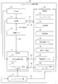
- FIG. 2 is a functional configuration diagram of a simulation reproduction device 100 according to Embodiment 1.
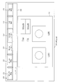
- FIG. FIG. 3 is a configuration diagram of a trace file 191 in the first embodiment.
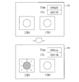
- FIG. 3 is a configuration diagram of a reproduction screen 200 in the first embodiment.
- FIG. 6 shows a change in the graphic display 210 according to the first embodiment.
- FIG. 6 is a diagram showing invalidation of a forward reproduction button 221 according to the first embodiment.
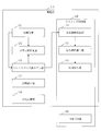
- 2 is a functional configuration diagram of a reproduction unit 110 according to Embodiment 1.
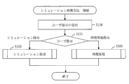
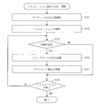
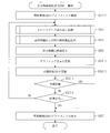
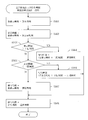
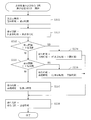
- FIG. 3 is a flowchart of a simulation reproduction method according to the first embodiment. 6 is a flowchart of simulation processing (S120) in the first embodiment. 5 is a flowchart of a reproduction process (S200) in the first embodiment.
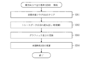
- FIG. 5 is a flowchart of initialization processing (S210) in the first embodiment.
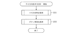
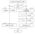
- 6 is a flowchart of non-direction processing (S220) in the first embodiment.
- FIG. 6 is a flowchart of button invalidation processing (S222) in the first embodiment.
- 5 is a flowchart of forward direction reproduction processing (S240) in the first embodiment.
- FIG. 5 is a flowchart of reverse direction reproduction processing (S250) in the first embodiment.
- 6 is a flowchart of trace data reading processing (S252) according to the first embodiment.
- FIG. 6 is a flowchart of forward frame advance processing (S260) in the first embodiment.
- 5 is a flowchart of reverse frame advance processing (S270) in the first embodiment.
- FIG. 10 is a configuration diagram of a trace file 191 in the second embodiment.
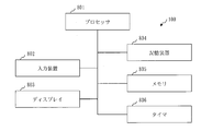
- FIG. The hardware block diagram of the simulation reproduction apparatus 100 in embodiment.
- Embodiment 1 A simulation reproduction apparatus 100 that reproduces a simulated operation of an object with a graphic display will be described with reference to FIGS. 1 to 20.
- the simulation reproduction apparatus 100 includes a reception unit 101, a reproduction unit 110, a reproduction clock unit 102, a display unit 120, a simulation unit 180, and a storage unit 190.
- the receiving unit 101 receives a user instruction input to the simulation reproduction device 100 by a user who uses the simulation reproduction device 100.
- the user instruction includes a simulation instruction and a reproduction instruction.
- the simulation instruction is an instruction for simulating a target operation.
- the reproduction instruction is an instruction to reproduce the simulated operation of the object in a graphic display.
- the reproduction instructions include a reproduction start instruction, a forward direction reproduction instruction, a reverse direction reproduction instruction, a pause instruction, a forward frame advance instruction, a backward frame advance instruction, and a parameter setting instruction.
- the reproduction start instruction is an instruction to start reproduction of the target motion.
- the forward direction reproduction instruction is an instruction for performing forward direction reproduction to reproduce the target operation in time order.
- the reverse direction reproduction instruction is an instruction for performing reverse direction reproduction to reproduce the target motion in reverse order of time.
- the pause instruction is an instruction to pause reproduction of the target motion.
- the forward frame advance instruction is an instruction to perform forward frame advance in which the target state changes once in time order.
- the reverse frame advance instruction is an instruction to perform reverse frame advance in which the target state changes once in the reverse order of the time.
- the parameter setting instruction is an instruction to set a parameter used when reproducing the target operation.
- the parameter setting instruction includes an upper limit cycle setting instruction and a lower limit cycle setting instruction.
- the upper limit cycle setting instruction is an instruction for setting the upper limit period 192
- the lower limit cycle setting instruction is an instruction for setting the lower limit period 193.
- the upper limit cycle 192 is an upper limit of the length of time that the object continues to be displayed without changing its state.
- the initial value of the upper limit cycle 192 is a value representing the longest cycle.
- the lower limit cycle 193 is a lower limit of the length of time that the object continues to be displayed without changing its state.
- the initial value of the lower limit cycle 193 is a value representing the shortest cycle.
- the simulation unit 180 simulates the target operation by executing a simulation program, and generates a trace file 191. While the target motion is being simulated, the simulated target motion is displayed graphically on the simulation screen.
- the simulation screen is generated by the simulation screen display unit 122 of the display unit 120.
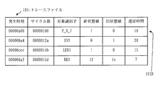
- the configuration of the trace file 191 will be described based on FIG.
- the trace file 191 is a file in which one or more trace data 191D is recorded.
- One line in the figure corresponds to one piece of trace data 191D.
- the trace data 191D includes an occurrence time, the number of cycles, a target identifier, a new state value, and an old state value.
- the occurrence time is the time when the change in the target state occurs.
- the cycle number is a value representing the generation time as a virtual clock count.
- a virtual clock is a clock of a virtual computer, and a virtual computer is a virtual computer on which an object operates.
- the occurrence time and the number of cycles have the following relationship.
- the target identifier identifies the target. Examples of objects are LEDs and peripheral devices.
- the new state value indicates the state of the target after the state of the target has changed.
- the old state value indicates the state of the object before the state of the object changes.
- One or more pieces of trace data 191D are recorded in the trace file 191 in order of time of occurrence.
- the reproduction unit 110 uses the trace file 191, the reproduction time 109, the upper limit cycle 192, the lower limit cycle 193, the initial state flag 194, and the operation impossibility information 195 in a graphic display.
- the reproduction time 109 is a time that reproduces the time of the time zone in which the target operation is simulated, and is acquired from the reproduction clock unit 102.
- the initial state flag 194 is a flag indicating whether or not the state of the target being reproduced is an initial state. A flag value indicating an initial state is set as an initial state value, and a flag value indicating a state other than the initial state is set as a non-initial state value.
- the operation impossibility information 195 is information indicating whether the target motion can be reproduced in the order of time and in the reverse order of the time.
- the reproduction clock unit 102 functions as a clock indicating the reproduction time 109.
- the reproduction time 109 is acquired from the reproduction unit 110, the display unit 120, and the simulation unit 180 as needed.
- the reproduction clock unit 102 advances the reproduction time 109 in time order.
- the reproduction clock unit 102 advances the reproduction time 109 in the reverse order.
- the display unit 120 includes a reproduction screen display unit 121 and a simulation screen display unit 122.
- the reproduction screen display unit 121 displays the reproduction screen 200 using the reproduction screen file 199 and the reproduction time 109.
- the reproduction screen file 199 is a file including images that constitute the reproduction screen 200.
- the reproduction screen 200 will be described with reference to FIG.
- the reproduction screen 200 includes a graphic display 210, a button widget 220, and a message area 230.
- the graphic display 210 is a graphic representing a change in the state of the simulated object.
- the graphic display 210 indicates the lighting states of the LEDs 1 and 2 for the LEDs 1 and 2.
- the graphic display 210 shows the reproduction time 109 and the number of clocks corresponding to the reproduction time 109.
- the time column in the figure shows the reproduction time 109, and the Clk column in the figure shows the number of clocks.
- the reproduction time 109 in the Time column and the number of clocks in the Clk column change with the reproduction time 109 of the reproduction clock unit 102. For example, when only LED 1 is turned on from the state where LED 1 and LED 2 are turned off, as shown in FIG. 4, the state of LED 1 changes from the turned off state to the turned on state.
- the button widget 220 includes a forward reproduction button 221, a backward reproduction button 222, a forward frame advance button 223, a backward frame advance button 224, an upper limit cycle button 225, and a lower limit cycle button 226.
- the forward reproduction button 221 is a button for reproducing the forward direction. When the forward reproduction button 221 is pressed, a forward reproduction instruction is accepted.
- the reverse direction reproduction button 222 is a button for reverse direction reproduction. When the reverse direction reproduction button 222 is pressed, a reverse direction reproduction instruction is accepted.
- the forward frame advance button 223 is a forward frame advance button. When the forward frame advance button 223 is pressed, a forward frame advance instruction is accepted.
- the reverse frame advance button 224 is a button for reverse frame advance.
- the upper limit cycle button 225 is a button for setting an upper limit cycle.
- the upper limit cycle button 225 is pressed, a dialog for designating the upper limit cycle 192 is displayed, and a setting instruction for the upper limit cycle 192 designated in the displayed dialog is accepted.
- the lower limit cycle button 226 is a button for setting a lower limit cycle. When the lower limit cycle button 226 is pressed, a dialog for specifying the lower limit cycle 193 is displayed, and a setting instruction for the lower limit cycle 193 specified in the displayed dialog is accepted.
- the reverse direction reproduction button 222 and the reverse direction frame advance button 224 are invalidated.
- the reverse direction reproduction button 222 and the reverse direction frame advance button 224 are invalidated, the reverse direction reproduction instruction and the reverse direction frame advance instruction are not accepted, and the reverse direction reproduction and the reverse direction frame advance are not performed.
- the operation impossibility information 195 indicates the forward direction as the operation impossibility direction
- the forward reproduction button 221 and the forward frame advance button 223 are invalidated.
- the forward reproduction button 221 and the forward frame advance button 223 are disabled, the forward reproduction instruction and the forward frame advance instruction are not accepted, and the forward reproduction and the forward frame advance are not performed.
- the display of the forward reproduction button 221 changes as shown in FIG. The same applies to the other buttons.
- the message area 230 is an area where a message is displayed. For example, when the invalidated forward direction reproduction button 221 is pressed, an error message indicating that the forward direction reproduction instruction is invalid is displayed in the message area 230.
- the simulation screen display unit 122 displays a simulation screen using the simulation screen file 189 and the reproduction time 109.
- the simulation screen file 189 is a file including images constituting the simulation screen.
- the simulation screen is a screen including a display corresponding to the graphic display 210 of the reproduction screen 200.
- the storage unit 190 stores data used, generated, or input / output by the simulation reproduction device 100.
- An example of data stored in the storage unit 190 is a trace file 191, an upper limit cycle 192, a lower limit cycle 193, an initial state flag 194, operation impossible information 195, a reproduction screen file 199, and a simulation screen file 189.
- the reproduction unit 110 includes an initialization unit 111, an impossible direction determination unit 112, a trace data reading unit 113, a display interval calculation unit 114, a waiting time calculation unit 115, and a time waiting unit 116. Furthermore, the reproduction unit 110 includes a cycle setting unit 117 and a reproduction control unit 119.
- the initialization unit 111 performs an initialization process for reproducing the target operation in a graphic display. Details of the initialization process will be described later.
- the unusable direction determination unit 112 performs unusable direction determination processing for determining a valid reproduction instruction and an invalid reproduction instruction based on the reference position of the trace file 191. Details of the unusable direction determination process will be described later.
- the trace data reading unit 113 reads the trace data 191D from the trace file 191.
- the trace data reading unit 113 reads the trace data 191D one by one in the order of time of occurrence.
- the trace data reading unit 113 reads the trace data 191D one by one in the reverse order of the generation time.
- the trace data reading unit 113 reads one trace data 191D in the order of time of occurrence.
- the trace data reading unit 113 reads one trace data 191D in the reverse order of the generation time.
- the trace data read this time is called new trace data.
- the time corresponding to the occurrence time included in the new trace data is called a new display time.
- the occurrence time included in the new trace data is the new display time.
- the new display time is the time that goes back the correction time from the occurrence time included in the new trace data.
- the correction time is a predetermined minute time.
- the previously read trace data is called old trace data.
- the time corresponding to the occurrence time included in the old trace data is called the old display time.
- the occurrence time included in the old trace data is the old display time.
- the time from the occurrence time included in the old trace data to the correction time is the old display time.
- the display interval calculation unit 114 calculates a display interval that is an interval between the new display time and the old display time.
- the display interval calculation unit 114 calculates an interval from the old display time to the new display time as the display interval.
- the display interval calculation unit 114 calculates an interval from the new display time to the old display time as the display interval.
- the waiting time calculation unit 115 calculates a waiting time until the target state is changed. When the interval between the new display time and the old display time is longer than the upper limit cycle 192, the wait time calculation unit 115 calculates the wait time using the old display time and the upper limit cycle 192. When the display interval calculated during the reproduction in the forward direction is longer than the upper limit cycle 192, the waiting time calculation unit 115 displays the reproduction time 109 indicated by the reproduction clock unit 102 and the time when the upper limit cycle 192 elapses from the old display time. Is calculated as a waiting time.
- the waiting time calculation unit 115 sets the interval between the reproduction time 109 indicated by the reproduction clock unit 102 and the time that goes back from the old display time to the upper limit cycle 192. Calculate as waiting time.
- the waiting time calculation unit 115 calculates the waiting time using the old display time and the lower limit cycle 193.
- the waiting time calculation unit 115 displays the reproduction time 109 indicated by the reproduction clock unit 102 and the time when the lower limit cycle 193 elapses from the old display time. Is calculated as a waiting time.
- the waiting time calculation unit 115 sets the interval between the reproduction time 109 indicated by the reproduction clock unit 102 and the time that goes back from the new display time to the lower limit cycle 193. Calculate as waiting time.
- the time waiting unit 116 waits until the calculated waiting time elapses.
- the cycle setting unit 117 sets the upper limit cycle 192 according to the upper limit cycle setting instruction, and sets the lower limit cycle 193 according to the lower limit cycle setting instruction.
- the reproduction control unit 119 performs processes other than the processes performed by the functions described above, among the processes performed by the reproduction unit 110.
- the display interval calculation unit 114, the waiting time calculation unit 115, the time waiting unit 116, and the reproduction clock unit 102 constitute a timing control unit 130.
- the timing control unit 130 obtains a timing for updating the graphic display 210 based on the new display time and the old display time. This timing is when the waiting time has elapsed.
- the processing of the timing control unit 130 is referred to as timing control processing.
- the reproduction screen display unit 121 changes the target state at the obtained timing.
- the reproduction screen display unit 121 displays the state of the graphically displayed target in the new trace data at a time shifted from the old display time by the upper limit cycle. Change to the state indicated by the state value. That is, when the time waiting unit 116 outputs an elapsed signal, the reproduction screen display unit 121 changes the target state to the state indicated by the new state value included in the new trace data.
- the reproduction clock unit 102 updates the reproduction time 109 to the new display time when the time waiting unit 116 outputs an elapsed signal.
- the reproduction unit 110 when the pause instruction is received, the reproduction unit 110, the reproduction screen display unit 121, and the reproduction clock unit 102 are temporarily stopped.
- the reproduction screen display unit 121 does not wait until the reproduction time 109 indicated by the reproduction clock unit 102 reaches the generation time included in the new trace data, but does not include it in the new trace data.
- the target state is changed to the state indicated by the new state value.
- the reproduction clock unit 102 updates the reproduction time 109 to the new display time when the target state changes to the state indicated by the new state value included in the new trace data.
- the operation of the simulation reproduction apparatus 100 corresponds to a simulation reproduction method.
- the simulation reproduction method corresponds to the processing procedure of the simulation reproduction program.
- a simulation reproduction method will be described with reference to FIG. S110 is a user instruction receiving process.
- the reception unit 101 receives a user instruction.
- the user instruction accepted is a simulation instruction or a reproduction start instruction.
- S120 is a simulation process.
- the simulation unit 180 simulates a target operation by executing a simulation program, and generates a trace file 191.
- the simulation process (S120) will be described.
- the simulation unit 180 instructs the simulation screen display unit 122 to initialize the graphic display.
- the simulation screen display unit 122 uses the simulation screen file 189 to display a simulation screen including the initial graphic display.
- the simulation unit 180 starts the simulation by starting the execution of the simulation program. Then, the simulation unit 180 stores the start time when the simulation is started in the storage unit 190.
- the simulation unit 180 In S124, the simulation unit 180 generates trace data 191D including the occurrence time, the number of cycles, the state identifier, the new state value, and the old state value, and records the generated trace data 191D in the trace file 191.
- the simulation unit 180 instructs the graphic display to be updated by inputting the state identifier and the new state value to the simulation screen display unit 122.
- the simulation screen display unit 122 then changes the target state identified by the state identifier to the state indicated by the new state value in the graphic display.
- S200 is a reproduction process.
- the reproduction unit 110 reproduces the target operation with a graphic display using the trace file 191.
- S210 is an initialization process.
- the initialization unit 111 performs an initialization process for starting reproduction of the target motion.
- step S211 the initialization unit 111 instructs the reproduction screen display unit 121 to initialize graphic display. Then, the reproduction screen display unit 121 displays the reproduction screen 200 including the graphic display 210 in the initial state using the reproduction screen file 199.
- the initialization unit 111 instructs the reproduction clock unit 102 to initialize the reproduction time 109. Then, the reproduction clock unit 102 initializes the reproduction time 109. That is, the reproduction clock unit 102 updates the reproduction time 109 to the initial value.
- the initial value of the reproduction time 109 is the start time when the simulation is started.
- the initialization unit 111 opens the trace file 191.
- a file reference pointer indicating a reference position in the trace file 191 is generated.
- the file reference pointer when the trace file 191 is opened indicates the trace data 191D at the head of the trace file 191, that is, the head of the time order.
- the initialization unit 111 initializes the initial state flag 194. That is, the initialization unit 111 sets an initial state value in the initial state flag 194. After S214, the initialization process (S210) ends.
- S220 is an unusable process.
- the unusable direction determination unit 112 determines an unusable direction in which the target motion cannot be reproduced.
- the impossibility direction is a forward direction meaning a time order or a reverse direction meaning a reverse order of time.
- the reproduction screen display unit 121 invalidates a button for instructing reproduction in the unusable direction.
- S220 the unusable direction process (S220) will be described.
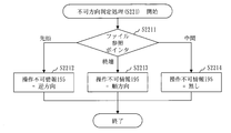
- S221 is an unusable direction determination process.
- the unusable direction determination unit 112 determines an unusable direction in which the target motion cannot be reproduced.
- step S2211 the impossible direction determination unit 112 determines the reference position indicated by the file reference pointer. If the file reference pointer indicates the beginning of the trace file 191, the process proceeds to S2212. If the file reference pointer indicates the end of the trace file 191, the process proceeds to S2213. If the file reference pointer indicates the middle of the trace file 191, the process proceeds to S2214.
- the impossibility direction determination unit 112 sets a value indicating the reverse direction in the operation impossibility information 195.
- the impossibility direction determination unit 112 sets a value indicating the forward direction in the operation impossibility information 195.
- the impossibility direction determination unit 112 sets a value indicating that there is no operation impossibility direction in the operation impossibility information 195. After S2212 to S2214, the impossible direction determination process (S221) ends.
- S222 is a button invalidation process.
- the reproduction screen display unit 121 invalidates a button for instructing reproduction in the unusable direction.
- the unusable direction process (S220) ends.
- the button invalidation process (S222) will be described with reference to FIG.
- the reproduction control unit 119 determines the operation impossible direction indicated by the operation impossible information 195. If the operation impossibility information 195 indicates the reverse direction, the process proceeds to S2222. If the operation impossibility information 195 indicates the forward direction, the process proceeds to S2223. When the operation impossibility information 195 indicates that there is no operation impossibility direction, the process proceeds to S2224.
- step S ⁇ b> 2222 the reproduction control unit 119 instructs the reproduction screen display unit 121 to invalidate the backward reproduction button 222 and the backward frame advance button 224. Then, the reproduction screen display unit 121 invalidates the reverse direction reproduction button 222 and the reverse direction frame advance button 224. Further, when the forward reproduction button 221 and the forward frame advance button 223 are disabled, the reproduction screen display unit 121 enables the forward reproduction button 221 and the forward frame advance button 223.
- step S ⁇ b> 2223 the reproduction control unit 119 instructs the reproduction screen display unit 121 to invalidate the forward reproduction button 221 and the forward frame advance button 223. Then, the reproduction screen display unit 121 disables the forward reproduction button 221 and the forward frame advance button 223. If the reverse direction reproduction button 222 and the reverse direction frame advance button 224 are disabled, the reproduction screen display unit 121 enables the reverse direction reproduction button 222 and the reverse direction frame advance button 224.
- step S2224 the reproduction control unit 119 instructs the reproduction screen display unit 121 to validate the reproduction instruction button. Then, the reproduction screen display unit 121 validates a disabled button among the forward direction reproduction button 221, the backward direction reproduction button 222, the forward direction frame advance button 223, and the backward direction frame advance button 224. After S2222 to S2224, the button invalidation processing (S222) ends.
- S230 is a reproduction instruction receiving process.
- the reception unit 101 receives a reproduction instruction.
- the reproduction instruction that is accepted is a forward direction reproduction instruction, a reverse direction reproduction instruction, a forward frame advance instruction, a backward frame advance instruction, an upper limit cycle setting instruction, or a lower limit period setting process.
- the process proceeds to S240. If the accepted reproduction instruction is a backward reproduction instruction, the process proceeds to S250. If the received reproduction instruction is a forward frame advance instruction, the process proceeds to S260. If the accepted reproduction instruction is a reverse frame advance instruction, the process proceeds to S270. When the accepted reproduction instruction is the upper limit cycle setting process, the process proceeds to S281. If the accepted reproduction instruction is the lower limit cycle setting process, the process proceeds to S282.
- S240 is a forward reproduction process.
- the reproduction unit 110 reproduces the target motion in the forward direction. Details of the forward reproduction process (S240) will be described later. After S240, the process returns to S220.
- S250 is a reverse direction reproduction process.
- the reproduction unit 110 reproduces the target motion in the reverse direction. Details of the reverse direction reproduction process (S250) will be described later. After S250, the process returns to S220.
- S260 is a forward frame advance process.
- the reproduction unit 110 changes the target state once in order of time. Details of the forward frame advance processing (S260) will be described later. After S260, the process returns to S220.
- S270 is a reverse frame advance process.
- the reproduction unit 110 changes the target state once in the reverse order of the time. Details of the reverse frame advance processing (S270) will be described later. After S270, the process returns to S220.
- S281 is an upper limit cycle setting process.
- the cycle setting unit 117 updates the upper limit cycle 192 stored in the storage unit 190 to the upper limit cycle specified by the upper limit cycle setting instruction. After S281, the process returns to S220.
- S282 is a lower limit cycle setting process.
- the cycle setting unit 117 updates the lower limit cycle 193 stored in the storage unit 190 to the lower limit cycle designated by the lower limit cycle setting instruction. After S282, the process returns to S220.
- the forward reproduction process (S240) will be described.
- the reproduction control unit 119 instructs the reproduction clock unit 102 to start incrementing the reproduction time 109.
- the reproduction clock unit 102 starts incrementing the reproduction time 109. That is, the reproduction clock unit 102 advances the reproduction time 109 in order of time.
- the reproduction control unit 119 clears the initial state flag 194. That is, the reproduction control unit 119 updates the flag value of the initial state flag 194 to a non-initial state value.
- S242 is a trace data reading process.
- the trace data reading unit 113 reads the trace data 191D indicated by the file reference pointer from the trace file 191. Then, the trace data reading unit 113 updates the file reference pointer to a value indicating the next trace data 191D in time order. Thereby, the trace data 191D can be read one by one in the time order. However, when there is no next trace data 191D in time order, that is, when the file reference pointer indicates the last trace data 191D, the trace data reading unit 113 updates the file reference pointer to a value indicating the end of the trace file 191. To do.
- S243 is a display interval and waiting time calculation process.
- the display interval calculation unit 114 calculates the display interval from the old display time to the new display time
- the wait time calculation unit 115 calculates the wait time until the new display time. Details of the display interval and waiting time calculation process (S243) will be described later.
- the time waiting unit 116 starts a waiting time timer in which the calculated waiting time is set, and waits until the waiting time timer times out.
- the waiting time timer is a timer that times out when the waiting time elapses. However, if the calculated waiting time is less than or equal to zero, S244 is not executed, and the process proceeds to S245-1.
- the reproduction control unit 119 calculates a new clock number using the new display time. In addition, the reproduction control unit 119 acquires a target identifier and a new state value from the read trace data 191D. Then, the reproduction control unit 119 inputs the new display time, the new clock number, the target identifier, and the new state value to the reproduction screen display unit 121.
- the reproduction screen display unit 121 changes the state of the target identified by the input target identifier to the state indicated by the input new state value in the graphic display 210 of the reproduction screen 200.
- the reproduction screen display unit 121 updates the reproduction time displayed on the graphic display 210 to the input new display time, and updates the clock number displayed on the graphic display 210 to the input new clock number. .
- the reproduction control unit 119 inputs the new display time to the reproduction clock unit 102. Then, the reproduction clock unit 102 updates the reproduction time 109 to the new display time, and advances the updated reproduction time 109 in order of time.
- the trace data reading unit 113 determines whether the file reference pointer indicates the end of the trace file 191. If the file reference pointer indicates the end of the trace file 191, the process proceeds to S247. If the file reference pointer does not indicate the end of the trace file 191, the process proceeds to S246-2.
- step S246-2 the reproduction control unit 119 inquires of the reception unit 101 whether a primary stop instruction has been received after the forward reproduction processing (S240) is started.
- the primary stop instruction is accepted after the forward reproduction process (S240) is started, the process proceeds to S247. If the primary stop instruction is not accepted after the forward reproduction process (S240) is started, the process returns to S242.
- the reproduction control unit 119 instructs the reproduction clock unit 102 to stop incrementing the reproduction time 109. Then, the reproduction clock unit 102 stops incrementing the reproduction time 109. That is, the reproduction clock unit 102 stops operating. After S247, the forward reproduction process (S240) ends.
- the display interval and waiting time calculation process (S243) will be described with reference to FIG.
- the display interval calculation unit 114 acquires the occurrence time from the trace data 191D read this time, and sets the acquired occurrence time as the new display time.
- S2432 is a display interval calculation process.
- the display interval calculation unit 114 calculates a display interval that is an interval from the old display time to the new display time.
- the old display time is the new display time calculated last time. However, when there is no new display time calculated last time, that is, when the new display time is calculated for the first time, the old display time is the initial value of the reproduction time 109.
- the waiting time calculation unit 115 compares the calculated display interval with the upper limit cycle 192. When the calculated display interval is longer than the upper limit cycle 192, the process proceeds to S2434. If the calculated display interval is equal to or less than the upper limit cycle 192, the process proceeds to S2435.
- the waiting time calculation unit 115 acquires the current reproduction time 109 from the reproduction clock unit 102. Then, the waiting time calculation unit 115 calculates an interval between the current reproduction time 109 and the time when the upper limit cycle 192 elapses from the old display time as a waiting time.
- the waiting time calculation unit 115 compares the calculated display interval with the lower limit cycle 193. When the calculated display interval is shorter than the lower limit cycle 193, the process proceeds to S2436. If the calculated display interval is equal to or longer than the lower limit cycle 193, the process proceeds to S2437.
- the waiting time calculation unit 115 acquires the current reproduction time 109 from the reproduction clock unit 102. Then, the waiting time calculation unit 115 calculates the interval between the current reproduction time 109 and the time when the lower limit cycle 193 elapses from the old display time as the waiting time.
- the waiting time calculation unit 115 acquires the current reproduction time 109 from the reproduction clock unit 102. Then, the waiting time calculation unit 115 calculates an interval from the current reproduction time 109 to the new display time as a waiting time.
- the reverse direction reproduction process (S250) will be described with reference to FIG.
- the reproduction control unit 119 instructs the reproduction clock unit 102 to start decrementing the reproduction time 109. Then, the reproduction clock unit 102 starts decrementing the reproduction time 109. That is, the reproduction clock unit 102 advances the reproduction time 109 in the reverse order.
- S252 is a trace data reading process.
- the trace data reading unit 113 reads one trace data 191D from the trace file 191 in reverse order of time. Details of the trace data reading process (S252) will be described later.
- S253 is a display interval and waiting time calculation process.
- the display interval calculation unit 114 calculates the display interval from the new display time to the old display time
- the wait time calculation unit 115 calculates the wait time until the new display time. Details of the display interval and waiting time calculation process (S253) will be described later.
- the time waiting unit 116 starts a waiting time timer in which the calculated waiting time is set, and waits until the waiting time timer times out.
- the waiting time timer is a timer that times out when the waiting time elapses. However, if the calculated waiting time is less than or equal to zero, S254 is not executed, and the process proceeds to S255-1.
- the reproduction control unit 119 calculates a new clock number using the new display time. Further, the reproduction control unit 119 acquires the target identifier and the old state value from the read trace data 191D. Then, the reproduction control unit 119 inputs the new display time, the new clock number, the target identifier, and the old state value to the reproduction screen display unit 121.
- the reproduction screen display unit 121 changes the state of the target identified by the input target identifier in the graphic display 210 of the reproduction screen 200 to the state indicated by the input old state value.
- the reproduction screen display unit 121 updates the reproduction time displayed on the graphic display 210 to the input new display time, and updates the clock number displayed on the graphic display 210 to the input new clock number. .
- the reproduction control unit 119 inputs the new display time to the reproduction clock unit 102. Then, the reproduction clock unit 102 updates the reproduction time 109 to the new display time and advances the updated reproduction time 109 in the reverse order.
- the trace data reading unit 113 determines whether the flag value of the initial state flag 194 is an initial state value. If the flag value of the initial state flag 194 is the initial state value, the process proceeds to S257. If the flag value of the initial state flag 194 is a non-initial state value, the process proceeds to S256-2.
- step S256-2 the reproduction control unit 119 inquires of the reception unit 101 whether a primary stop instruction has been received after the reverse direction reproduction process (S250) is started.
- the process proceeds to S257. If the primary stop instruction has not been accepted after the reverse reproduction process (S250) has been started, the process returns to S252.
- the reproduction control unit 119 instructs the reproduction clock unit 102 to stop decrementing the reproduction time 109. Then, the reproduction clock unit 102 stops decrementing the reproduction time 109. That is, the reproduction clock unit 102 stops operating.
- the reverse reproduction process (S250) ends.
- step S2521 the reproduction control unit 119 determines whether the file reference pointer indicates the top trace data 191D of the trace file 191, that is, the top trace data 191D in time order. If the file reference pointer indicates the beginning of the trace file 191, the process proceeds to S2522. If the file reference pointer indicates other than the beginning of the trace file 191, the process proceeds to S2524.
- step S2522 the reproduction control unit 119 instructs the reproduction clock unit 102 to initialize the reproduction time 109. Then, the reproduction control unit 119 initializes the reproduction time 109. That is, the reproduction control unit 119 updates the reproduction time 109 to the initial value.
- the reproduction control unit 119 initializes the initial state flag 194. That is, the reproduction control unit 119 updates the flag value of the initial state flag 194 to the initial state value.
- the trace data reading process (S252) ends.
- the reproduction control unit 119 updates the file reference pointer to a value indicating the next trace data 191D in the reverse order of time.
- step S2525 the trace data reading unit 113 reads the trace data 191D indicated by the file reference pointer from the trace file 191. After S2525, the trace data reading process (S252) ends.
- the display interval and waiting time calculation process (S253) will be described.
- the display interval calculation unit 114 acquires the occurrence time from the trace data 191D read this time, and calculates a time that goes back the correction time from the acquired occurrence time as a new display time.
- This new display time means the time immediately before the target state changes.
- S2532 is a display interval calculation process.
- the display interval calculation unit 114 calculates a display interval that is an interval from the new display time to the old display time.
- the old display time is the new display time calculated last time.
- the waiting time calculation unit 115 compares the calculated display interval with the upper limit cycle 192. If the calculated display interval is longer than the upper limit cycle 192, the process proceeds to S2534. If the calculated display interval is equal to or less than the upper limit cycle 192, the process proceeds to S2535.
- step S ⁇ b> 2534 the waiting time calculation unit 115 acquires the current reproduction time 109 from the reproduction clock unit 102. Then, the waiting time calculation unit 115 calculates the interval between the current reproduction time 109 and the time that goes back the upper limit cycle 192 from the old display time as the waiting time.
- the waiting time calculation unit 115 compares the calculated display interval with the lower limit cycle 193. If the calculated display interval is shorter than the lower limit cycle 193, the process proceeds to S2536. If the calculated display interval is equal to or longer than the lower limit cycle 193, the process proceeds to S2537.
- the waiting time calculation unit 115 acquires the current reproduction time 109 from the reproduction clock unit 102. Then, the waiting time calculation unit 115 calculates the interval between the current reproduction time 109 and the time that goes back the lower limit cycle 193 from the old display time as the waiting time.
- step S ⁇ b> 2537 the waiting time calculation unit 115 acquires the current reproduction time 109 from the reproduction clock unit 102. Then, the waiting time calculation unit 115 calculates an interval from the current reproduction time 109 to the new display time as a waiting time.
- the forward frame advance process (S260) will be described with reference to FIG.
- the reproduction control unit 119 clears the initial state flag 194. That is, the reproduction control unit 119 updates the flag value of the initial state flag 194 to a non-initial state value.
- the trace data reading unit 113 reads the trace data 191D indicated by the file reference pointer from the trace file 191. Then, the trace data reading unit 113 updates the file reference pointer to a value indicating the next trace data 191D in time order. However, when there is no next trace data 191D in time order, that is, when the file reference pointer indicates the last trace data 191D, the trace data reading unit 113 updates the file reference pointer to a value indicating the end of the trace file 191. To do.
- the reproduction control unit 119 acquires the generation time, the number of cycles, the target identifier, and the new state value from the read trace data 191D, and the acquired generation time, the number of cycles, the target identifier, and the new state value. Input to the reproduction screen display unit 121.
- the reproduction screen display unit 121 changes the state of the target identified by the input target identifier to the state indicated by the input new state value in the graphic display 210 of the reproduction screen 200.
- the reproduction screen display unit 121 updates the reproduction time displayed on the graphic display 210 to the input occurrence time, and updates the number of clocks displayed on the graphic display 210 to the input cycle number.
- the reproduction control unit 119 inputs the acquired occurrence time to the reproduction clock unit 102. Then, the reproduction clock unit 102 updates the reproduction time 109 to the generation time. After S264, the forward frame advance processing (S260) ends.
- step S271 the reproduction control unit 119 determines whether the file reference pointer indicates the top trace data 191D of the trace file 191, that is, the top trace data 191D in time order. If the file reference pointer indicates the beginning of the trace file 191, the process proceeds to S272. If the file reference pointer indicates a position other than the head of the trace file 191, the process proceeds to S274.
- the reproduction control unit 119 initializes the initial state flag 194. That is, the reproduction control unit 119 updates the flag value of the initial state flag 194 to the initial state value.
- step S273 the reproduction control unit 119 instructs the reproduction clock unit 102 to initialize the reproduction time 109. Then, the reproduction clock unit 102 initializes the reproduction time 109. That is, the reproduction clock unit 102 updates the reproduction time 109 to the initial value.
- the reverse frame advance processing (S270) ends.
- the reproduction control unit 119 updates the file reference pointer to a value indicating the next trace data 191D in the reverse order of time.
- the trace data reading unit 113 reads the trace data 191D indicated by the file reference pointer from the trace file 191.
- the reproduction control unit 119 acquires the occurrence time, the state identifier, and the old state value from the read trace data 191D.
- the reproduction control unit 119 calculates a time that goes back the correction time from the acquired occurrence time as a new display time.
- This new display time means the time immediately before the target state changes.
- the reproduction control unit 119 calculates a new clock number using the calculated new display time.
- the reproduction control unit 119 inputs the new display time, the new clock number, the state identifier, and the old state value to the reproduction screen display unit 121.
- the reproduction screen display unit 121 changes the state of the target identified by the input target identifier to the state indicated by the input old state value in the graphic display 210 of the reproduction screen 200.
- the reproduction screen display unit 121 updates the reproduction time displayed on the graphic display 210 to the input new display time, and updates the clock number displayed on the graphic display 210 to the input new clock number. .
- the reproduction control unit 119 inputs the new display time to the reproduction clock unit 102. Then, the reproduction clock unit 102 updates the reproduction time 109 to the new display time. After S277, the reverse frame advance processing (S270) ends.
- the simulation reproducing apparatus 100 pauses the change of the target state according to the pause instruction, and changes the target state once in the reverse order of the time according to the reverse frame advance instruction. Therefore, the user can check the change in the target state retroactively. And when a malfunction occurs, the cause can be easily identified.
- the simulation reproducing apparatus 100 changes the target state once each in accordance with the forward frame advance instruction and the backward frame advance instruction. Therefore, the user can confirm the change of the target state one by one.
- the simulation reproduction apparatus 100 continuously changes the target state in the reverse order of time according to the backward reproduction instruction. Therefore, the user can continuously check the change in the target state in the reverse order of the time by one backward reproduction instruction without performing the backward frame advance instruction a plurality of times.
- the simulation reproducing apparatus 100 sets the upper limit cycle 192 in accordance with the upper limit cycle setting instruction, and makes the time during which the object continues to be displayed without changing the state shorter than the upper limit cycle 192. Therefore, when the target state does not change for a long time, the user can shorten the time required for the confirmation work by shortening the upper limit cycle 192 by an upper limit cycle setting instruction.
- the simulation reproducing apparatus 100 sets the lower limit cycle 193 according to the lower limit cycle setting instruction, and makes the time during which the object continues to be displayed without changing the state longer than the lower limit cycle 193. Therefore, when the target state changes at a high speed, the user can prevent an oversight of confirmation by lengthening the lower limit cycle 193 by a lower limit cycle setting instruction.
- the simulation reproduction apparatus 100 applies both the upper limit cycle 192 and the lower limit cycle 193 in a compatible manner. Therefore, the user can obtain the effects of both shortening and extending the time for which the object continues to be displayed without changing the state.
- the simulation reproducing apparatus 100 displays a time which is a minute time from the generation time and goes back to the graphic display 210 during backward reproduction or backward frame advance.
- a time which is a minute time from the generation time and goes back to the graphic display 210 during backward reproduction or backward frame advance.
- Embodiment 2 A form in which the delay time generated when the graphic display representing the state of the object in the simulation changes is considered when reproducing the operation of the object will be described with reference to FIGS. However, the description which overlaps with Embodiment 1 is abbreviate
- the functional configuration of the simulation reproduction apparatus 100 is the same as that of the first embodiment except for the following points.
- the trace data 191D of the trace file 191 includes a delay time as shown in FIG.
- the delay time is a time generated when the graphic display representing the target state is changed in the simulation.
- the waiting time calculation unit 115 corrects the waiting time by subtracting the delay time included in the new trace data from the calculated waiting time.
- the reproduction screen display unit 121 changes the target state when the corrected waiting time has elapsed.
- the reproduction clock unit 102 updates the reproduction time 109 to the new display time when the corrected waiting time has elapsed.
- S125 of the simulation process (S120) described in FIG. 8 is different from that of the first embodiment as follows.
- the simulation unit 180 when the simulation unit 180 instructs the simulation screen display unit 122 to update the graphic display, the simulation unit 180 starts measuring the update completion time.
- the simulation screen display unit 122 outputs an update completion notification when the graphic display update is completed.
- the output update completion notification is input to the simulation unit 180.
- the simulation unit 180 finishes measuring the update completion time when the update completion notification is input.
- the update completion time is the time required for updating the graphic display, and can be expressed by the following equation.
- the update instruction time is the time when the simulation unit 180 instructs the simulation screen display unit 122 to update the graphic display.
- the update completion time is the time when the update completion notification is input to the simulation unit 180.
- Update completion time Update completion time-Update instruction time
- the simulation unit 180 calculates a time obtained by subtracting the specified time from the update completion time as a delay time, and sets the calculated delay time in the recorded trace data 191D.
- the specified time is a predetermined time.
- An example of the prescribed time is the update completion notification transmission time or the update completion notification transmission time plus the target response time.
- the update completion notification transmission time is the time from when the update completion notification is output from the simulation screen display unit 122 to when the output update completion notification is input to the simulation unit 180.
- the response time of the target is about 50 to 100 nanoseconds.
- the display interval and waiting time calculation process (S243) will be described with reference to FIG.
- the display interval and waiting time calculation process (S243) includes S2438 in addition to S2431 to S2437 described in the first embodiment.
- the waiting time calculation unit 115 acquires a delay time from the read trace data 191D. Then, the waiting time calculation unit 115 corrects the waiting time by subtracting the acquired delay time from the calculated waiting time.
- the time waiting unit 116 waits until the corrected waiting time elapses in S244 of the forward reproduction process (S240) described with reference to FIG.
- the display interval and waiting time calculation process (S253) includes S2538 in addition to S2531 to S2537 described in the first embodiment.
- the waiting time calculation unit 115 acquires a delay time from the read trace data 191D. Then, the waiting time calculation unit 115 corrects the waiting time by subtracting the acquired delay time from the calculated waiting time.
- the time waiting unit 116 waits until the corrected waiting time elapses in S254 of the reverse direction reproduction process (S250) described in FIG.
- the simulation reproduction apparatus 100 corrects the waiting time by subtracting the delay time from the waiting time. Thereby, the change in the state of the target can be reproduced with a graphic display closer to the target of the actual machine.
- Each embodiment is an example of a preferred embodiment and is not intended to limit the technical scope of the present invention. Each embodiment may be implemented partially or in combination with other embodiments.
- the processing procedure described using the flowchart and the like is an example of the processing procedure of the simulation reproduction method and the simulation reproduction program.
- the trace file 191 may be either a normal file stored on the hard disk or a memory mapped file read into the memory. By replacing the file reference pointer with a memory address, the trace file 191 can be handled in a normal memory space.
- the simulation unit 180 may set either the generation time or the number of cycles in the trace data 191D during simulation. Further, the simulation reproduction apparatus 100 may include a mechanism for converting the generation time (or the number of cycles) set in the trace data 191D into the number of cycles (or the generation time). The mechanism may perform conversion by multiplying by the speed ratio as in Patent Document 1. The conversion may be performed when the trace data 191D is read.
- the time waiting unit 116 may detect the elapse of the waiting time using a one-shot timer, or may detect the elapse of the waiting time by polling the reproduction time 109. Similar to a general microcomputer simulator, the simulation unit 180 may perform the simulation by any one of the first method and the second method.
- the first method is a method in which the instruction of the simulation program is converted into an instruction for a virtual microcomputer, and the converted instruction is executed by the virtual microcomputer.
- the second method is a method in which a simulation program instruction is converted into a host processor instruction, and the converted instruction is executed by the host processor.
- the simulation reproduction apparatus 100 is realized by executing a simulation program and a simulation reproduction program by a server, workstation, personal computer, or other computer on which an operating system is operating.
- the simulation reproduction device 100 includes a processor 801, an input device 802, a display 803, a storage device 804, a memory 805, and a timer 806.
- the simulation program and the simulation reproduction program are stored in the memory 805 and executed by the processor 801.
- Data used, generated or input / output by the simulation reproduction apparatus 100 is stored in the memory 805 or the storage device 804.
- An example of the storage device 804 is a hard disk or a nonvolatile memory.
- the user instruction is input to the simulation reproducing apparatus 100 using an input device 802 such as a keyboard, a mouse, a pointing device, or a touch panel.
- the operation screen, simulation screen, and reproduction screen 200 of the simulation reproduction apparatus 100 are displayed on the display 803.
- the accepting unit 101 is realized by a processor 801, an input device 802, and a display 803.
- the reproduction clock unit 102 is realized by a processor 801, a memory 805, and a timer 806.
- the reproduction unit 110 and the simulation unit 180 are realized by a processor 801, a memory 805, and a timer 806.
- the display unit 120 is realized by a processor 801, a memory 805, and a display 803.
- the storage unit 190 is realized by the memory 805 and the storage device 804.
- 100 simulation reproduction device 101 reception unit, 102 reproduction clock unit, 109 reproduction time, 110 reproduction unit, 111 initialization unit, 112 impossible direction determination unit, 113 trace data reading unit, 114 display interval calculation unit, 115 waiting time calculation unit 116, time waiting unit, 117 period setting unit, 119 reproduction control unit, 120 display unit, 121 reproduction screen display unit, 122 simulation screen display unit, 130 timing control unit, 180 simulation unit, 189 simulation screen file, 190 storage unit, 191 trace file, 191D trace data, 192 upper limit cycle, 193 lower limit cycle, 194 initial status flag, 195 operation impossible information, 199 reproduction screen file, 200 reproduction screen, 210 graph Display, 220 button widget, 221 forward reproduction button, 222 backward reproduction button, 223 forward frame advance button, 224 backward frame advance button, 225 upper limit cycle button, 226 lower limit cycle button, 230 message area, 801 processor , 802 input device, 803 display, 804 storage device, 805 memory, 806 timer.
Landscapes
- Engineering & Computer Science (AREA)
- Theoretical Computer Science (AREA)
- General Engineering & Computer Science (AREA)
- Physics & Mathematics (AREA)
- General Physics & Mathematics (AREA)
- Computer Hardware Design (AREA)
- Quality & Reliability (AREA)
- Software Systems (AREA)
- Evolutionary Computation (AREA)
- Geometry (AREA)
- Debugging And Monitoring (AREA)
Abstract
L'invention concerne une unité de mémorisation (190) qui mémorise un fichier trace (191) obtenu par simulation d'une action de sujet. Une unité d'acceptation (101) accepte une instruction de reproduction de direction vers l'avant. Une unité de reproduction (110) extrait des données de trace, une instance à la fois, du fichier trace. Sur la base d'une nouvelle estampille temporelle d'affichage qui correspond à une estampille temporelle d'occurrence qui est comprise dans de nouvelles données de trace qui sont extraites à l'instant présent et d'une ancienne estampille temporelle d'affichage qui correspond à une estampille temporelle d'occurrence qui est comprise dans d'anciennes données de trace qui ont été extraites à un instant précédent, l'unité de reproduction dérive une temporisation à laquelle est mis à jour un affichage graphique. À la temporisation dérivée, une unité d'affichage (120) fait passer l'état de sujet affiché graphiquement à un état qui est signifié par une nouvelle valeur d'état qui est comprise dans les nouvelles données de trace.
Priority Applications (5)
| Application Number | Priority Date | Filing Date | Title |
|---|---|---|---|
| JP2017517479A JP6272563B2 (ja) | 2015-05-11 | 2015-05-11 | シミュレーション再現装置、シミュレーション再現方法およびシミュレーション再現プログラム |
| US15/559,776 US10372576B2 (en) | 2015-05-11 | 2015-05-11 | Simulation reproduction apparatus, simulation reproduction method, and computer readable medium |
| EP15891781.5A EP3296875B1 (fr) | 2015-05-11 | 2015-05-11 | Dispositif, procédé et programme de reproduction de simulation |
| PCT/JP2015/063470 WO2016181455A1 (fr) | 2015-05-11 | 2015-05-11 | Dispositif, procédé et programme de reproduction de simulation |
| TW104120463A TW201640348A (zh) | 2015-05-11 | 2015-06-25 | 模擬再現裝置、模擬再現方法以及模擬再現程式產品 |
Applications Claiming Priority (1)
| Application Number | Priority Date | Filing Date | Title |
|---|---|---|---|
| PCT/JP2015/063470 WO2016181455A1 (fr) | 2015-05-11 | 2015-05-11 | Dispositif, procédé et programme de reproduction de simulation |
Publications (1)
| Publication Number | Publication Date |
|---|---|
| WO2016181455A1 true WO2016181455A1 (fr) | 2016-11-17 |
Family
ID=57249055
Family Applications (1)
| Application Number | Title | Priority Date | Filing Date |
|---|---|---|---|
| PCT/JP2015/063470 Ceased WO2016181455A1 (fr) | 2015-05-11 | 2015-05-11 | Dispositif, procédé et programme de reproduction de simulation |
Country Status (5)
| Country | Link |
|---|---|
| US (1) | US10372576B2 (fr) |
| EP (1) | EP3296875B1 (fr) |
| JP (1) | JP6272563B2 (fr) |
| TW (1) | TW201640348A (fr) |
| WO (1) | WO2016181455A1 (fr) |
Cited By (2)
| Publication number | Priority date | Publication date | Assignee | Title |
|---|---|---|---|---|
| EP3462261A1 (fr) | 2017-09-27 | 2019-04-03 | Omron Corporation | Appareil de traitement d'informations, procédé de traitement d'informations et programme |
| CN113939809A (zh) * | 2019-05-29 | 2022-01-14 | 微软技术许可有限责任公司 | 将存储器支持对象公开为可查询存储器资源 |
Families Citing this family (3)
| Publication number | Priority date | Publication date | Assignee | Title |
|---|---|---|---|---|
| US11599688B2 (en) * | 2018-02-26 | 2023-03-07 | Noblis, Inc. | Multi-layer cyber-physical systems simulation platform |
| US11036903B2 (en) | 2018-08-06 | 2021-06-15 | Noblis, Inc. | Data structures and processing methods for highly scalable simulation platforms |
| JP2023008828A (ja) * | 2021-07-02 | 2023-01-19 | キヤノン株式会社 | 撮像装置、撮像装置の制御方法、プログラム、及び情報処理装置 |
Citations (3)
| Publication number | Priority date | Publication date | Assignee | Title |
|---|---|---|---|---|
| JPH1011118A (ja) * | 1996-06-24 | 1998-01-16 | Keyence Corp | シーケンス制御装置、データ処理装置、データ記録再生方法、及び記録媒体 |
| JP2007334812A (ja) * | 2006-06-19 | 2007-12-27 | Nec Electronics Corp | シミュレータ及びシミュレーション方法 |
| JP2010009497A (ja) * | 2008-06-30 | 2010-01-14 | Digital Electronics Corp | 表示器、表示器の制御方法および表示器の制御プログラム |
Family Cites Families (13)
| Publication number | Priority date | Publication date | Assignee | Title |
|---|---|---|---|---|
| JPH07271629A (ja) | 1994-03-29 | 1995-10-20 | Mitsubishi Electric Corp | マイクロコンピュータ |
| JPH10333938A (ja) | 1997-06-04 | 1998-12-18 | Toshiba Corp | 計算機システムにおける実行ログの記録、表示方法、ならびに同方法を用いた計算機システム、及び同方法がプログラムされ記録される記録媒体 |
| JP4290266B2 (ja) | 1999-03-15 | 2009-07-01 | 三菱電機株式会社 | 並列分散シミュレーションシステム及び並列分散シミュレーション方法 |
| US7130783B1 (en) * | 2001-01-12 | 2006-10-31 | Synopsys, Inc. | Simulation-based functional verification of microcircuit designs |
| JP2005234617A (ja) | 2004-02-17 | 2005-09-02 | Sony Corp | マルチプロセッサデバッガおよびデバッグ方法 |
| JP4533682B2 (ja) | 2004-06-29 | 2010-09-01 | 株式会社東芝 | トレース解析装置およびトレース解析方法 |
| JP4760247B2 (ja) | 2005-09-13 | 2011-08-31 | 富士ゼロックス株式会社 | 情報提示装置及び情報提示方法、並びにコンピュータ・プログラム |
| US20090103902A1 (en) * | 2006-03-24 | 2009-04-23 | Matsushita Electric Industrial Co., Ltd. | Reproduction device, debug device, system lsi, and program |
| US20100180245A1 (en) * | 2006-08-11 | 2010-07-15 | Nxp, B.V. | Methods and products for determining and visualizin ic behavior |
| JP5395397B2 (ja) | 2008-10-16 | 2014-01-22 | 富士通テン株式会社 | シミュレーションシステム |
| JP5648186B2 (ja) | 2011-08-22 | 2015-01-07 | インターナショナル・ビジネス・マシーンズ・コーポレーションInternational Business Machines Corporation | トランザクションを再生するためのデータを生成する装置及び方法 |
| JP5982845B2 (ja) | 2012-02-08 | 2016-08-31 | 日本電気株式会社 | トレース制御装置及びトレース制御方法 |
| WO2014118897A1 (fr) * | 2013-01-29 | 2014-08-07 | 富士通株式会社 | Dispositif, procédé et programme de traitement d'informations |
-
2015
- 2015-05-11 EP EP15891781.5A patent/EP3296875B1/fr active Active
- 2015-05-11 WO PCT/JP2015/063470 patent/WO2016181455A1/fr not_active Ceased
- 2015-05-11 US US15/559,776 patent/US10372576B2/en not_active Expired - Fee Related
- 2015-05-11 JP JP2017517479A patent/JP6272563B2/ja not_active Expired - Fee Related
- 2015-06-25 TW TW104120463A patent/TW201640348A/zh unknown
Patent Citations (3)
| Publication number | Priority date | Publication date | Assignee | Title |
|---|---|---|---|---|
| JPH1011118A (ja) * | 1996-06-24 | 1998-01-16 | Keyence Corp | シーケンス制御装置、データ処理装置、データ記録再生方法、及び記録媒体 |
| JP2007334812A (ja) * | 2006-06-19 | 2007-12-27 | Nec Electronics Corp | シミュレータ及びシミュレーション方法 |
| JP2010009497A (ja) * | 2008-06-30 | 2010-01-14 | Digital Electronics Corp | 表示器、表示器の制御方法および表示器の制御プログラム |
Non-Patent Citations (1)
| Title |
|---|
| See also references of EP3296875A4 * |
Cited By (3)
| Publication number | Priority date | Publication date | Assignee | Title |
|---|---|---|---|---|
| EP3462261A1 (fr) | 2017-09-27 | 2019-04-03 | Omron Corporation | Appareil de traitement d'informations, procédé de traitement d'informations et programme |
| US10860010B2 (en) | 2017-09-27 | 2020-12-08 | Omron Corporation | Information processing apparatus for estimating behaviour of driving device that drives control target, information processing method and computer readable recording medium |
| CN113939809A (zh) * | 2019-05-29 | 2022-01-14 | 微软技术许可有限责任公司 | 将存储器支持对象公开为可查询存储器资源 |
Also Published As
| Publication number | Publication date |
|---|---|
| EP3296875A4 (fr) | 2018-04-18 |
| EP3296875A1 (fr) | 2018-03-21 |
| JPWO2016181455A1 (ja) | 2017-06-29 |
| US20180067832A1 (en) | 2018-03-08 |
| TW201640348A (zh) | 2016-11-16 |
| US10372576B2 (en) | 2019-08-06 |
| JP6272563B2 (ja) | 2018-01-31 |
| EP3296875B1 (fr) | 2019-09-18 |
Similar Documents
| Publication | Publication Date | Title |
|---|---|---|
| JP6272563B2 (ja) | シミュレーション再現装置、シミュレーション再現方法およびシミュレーション再現プログラム | |
| US6915416B2 (en) | Apparatus and method for microcontroller debugging | |
| US20160048302A1 (en) | Automatically Capturing User Interactions And Evaluating User Interfaces In Software Programs Using Field Testing | |
| Wimmer et al. | On the latency of USB-connected input devices | |
| CN107656620B (zh) | 虚拟对象控制方法、装置、电子设备及存储介质 | |
| WO2018099246A1 (fr) | Procédé et appareil de détection de débogage d'écran tactile, et support d'informations informatique associé | |
| JP4468410B2 (ja) | ソフトウェア実行装置および協調動作方法 | |
| WO2022100033A1 (fr) | Procédé et appareil de débogage d'applet, dispositif électronique et support de stockage | |
| JPWO2017179120A1 (ja) | シミュレーション再現装置およびシミュレーション再現プログラム | |
| TWI661358B (zh) | 模擬裝置 | |
| WO2012077704A1 (fr) | Serveur de souche de débogage, procédé de débogage et programme | |
| JP4472615B2 (ja) | プログラマブルデバイスのモデリング方法および装置 | |
| CN111190826B (zh) | 一种虚拟现实沉浸式追踪环境的测试方法、装置、存储介质及设备 | |
| TWI719571B (zh) | 測試觸控式行動裝置之測試裝置、測試系統及其電腦程式產品 | |
| JP2001209411A (ja) | Plcシミュレータ | |
| TWI660292B (zh) | 游標移動輔助系統及方法 | |
| JP2007334812A (ja) | シミュレータ及びシミュレーション方法 | |
| JP2005353020A (ja) | コンピュータプログラムのシミュレーション方式 | |
| JP2016045676A (ja) | デバッグ回路、デバッガ装置、半導体装置及びデバッグ方法 | |
| TWM462860U (zh) | 提供圖形化接腳介面之調試系統與裝置 | |
| JP2013045177A (ja) | 情報処理装置及びプログラム | |
| JP2013109621A (ja) | インサーキットエミュレータ、トレースメモリ制御装置、トレースメッセージ生成装置及びトレースメッセージ処理方法 | |
| JP5729896B2 (ja) | 機器組込み用ソフトウェアの開発支援システムおよび開発支援方法 | |
| JP2018067057A (ja) | 制御プログラムの検証装置及びプログラム | |
| CN112561752A (zh) | 工业设备操作考核系统、数据处理方法、装置和存储介质 |
Legal Events
| Date | Code | Title | Description |
|---|---|---|---|
| 121 | Ep: the epo has been informed by wipo that ep was designated in this application |
Ref document number: 15891781 Country of ref document: EP Kind code of ref document: A1 |
|
| ENP | Entry into the national phase |
Ref document number: 2017517479 Country of ref document: JP Kind code of ref document: A |
|
| WWE | Wipo information: entry into national phase |
Ref document number: 15559776 Country of ref document: US |
|
| NENP | Non-entry into the national phase |
Ref country code: DE |