WO2016181533A1 - Dispositif de correction de dentition - Google Patents
Dispositif de correction de dentition Download PDFInfo
- Publication number
- WO2016181533A1 WO2016181533A1 PCT/JP2015/063809 JP2015063809W WO2016181533A1 WO 2016181533 A1 WO2016181533 A1 WO 2016181533A1 JP 2015063809 W JP2015063809 W JP 2015063809W WO 2016181533 A1 WO2016181533 A1 WO 2016181533A1
- Authority
- WO
- WIPO (PCT)
- Prior art keywords
- cover
- main body
- shaft
- slot
- orthodontic
- Prior art date
- Legal status (The legal status is an assumption and is not a legal conclusion. Google has not performed a legal analysis and makes no representation as to the accuracy of the status listed.)
- Ceased
Links
Images


Classifications
-
- A—HUMAN NECESSITIES
- A61—MEDICAL OR VETERINARY SCIENCE; HYGIENE
- A61C—DENTISTRY; APPARATUS OR METHODS FOR ORAL OR DENTAL HYGIENE
- A61C7/00—Orthodontics, i.e. obtaining or maintaining the desired position of teeth, e.g. by straightening, evening, regulating, separating, or by correcting malocclusions
- A61C7/12—Brackets; Arch wires; Combinations thereof; Accessories therefor
- A61C7/28—Securing arch wire to bracket
- A61C7/30—Securing arch wire to bracket by resilient means; Dispensers therefor
Definitions
- the present invention relates to an orthodontic apparatus used for correcting misaligned teeth and twisted teeth.
- An orthodontic correction method using an orthodontic appliance is known.
- a plurality of orthodontic devices are attached to the patient's teeth, the archwire is bridged over the orthodontic device, and the orthodontic force is applied to the patient's teeth by the archwire to correct the dentition.
- the archwire is replaced according to the progress stage of the treatment, and the correction of the dentition is promoted.
- the archwire is inserted into a slot provided in the body of the orthodontic appliance, and the opening of the slot is closed by the cover.
- Patent Document 1 discloses an orthodontic apparatus having a cap-type cover.
- the cap-type cover When the cap-type cover is removed from the main body, the cover is plastically deformed. When the removed cover is attached to the main body again, it may drop off or be damaged. For this reason, when the cover is removed from the main body in order to replace the archwire, it is necessary to attach a new cover, which increases the labor of the operator and the cost burden on the patient.
- Patent Document 2 an orthodontic apparatus provided with a clip-type cover is known in Patent Document 2 and the like.
- This clip-type cover is attached to the main body so that the opening of the slot can be opened and closed. By opening and closing this slot, the archwire can be easily replaced.
- This clip-type cover is basically impossible to replace so that the cover does not fall into the oral cavity during treatment. However, when the cover is damaged or the cover is washed, it is necessary to remove the cover from the main body and replace it with a new cover.
- Patent Document 2 discloses a detachable clip type cover. This clip-type cover is configured so that it cannot be removed without using a dedicated tool, and is prevented from falling off during treatment.
- the orthodontic appliance of Patent Document 2 it is very difficult to remove the cover while the body is attached to the patient's teeth.
- the orthodontic apparatus of Patent Document 2 it is necessary to insert a dedicated tool into the narrow gap from the gingival side, but it is difficult to perform the operation in a narrow oral cavity.
- an object of the present invention is to provide an orthodontic apparatus capable of opening a slot without removing the cover from the main body and easily replacing the cover.
- the present invention provides the following. (1) a base whose bottom surface is directly or indirectly fixed to a tooth; A main body provided on the upper surface of the base, comprising a slot extending in a near-centrifugal direction and opening upward and accommodating an archwire; A cover having a closing portion capable of closing the opening of the slot, The cover has a claw portion provided in one of the directions crossing the near-centrifugal direction, The body is The slot provided at approximately the center in the direction crossing the near-centrifugation direction; Provided in one of the directions crossing the near-centrifugation direction, and having a locking portion that locks the claw portion on the surface on the base side, A shaft portion is provided on one of the other side of the cover in the direction intersecting the near-centrifugation direction, or the other side of the main body in the direction intersecting the near-centrifugation direction, A shaft housing portion that rotatably accommodates the shaft portion is provided on either the other side of the main body in the direction intersecting
- the cover may include an overhanging portion that extends from the blocking portion in a near-centrifugal direction and toward the bottom of the slot.
- the main body may include a step or a taper corresponding to the protruding portion.
- a notch portion into which the tip of the release tool is inserted may be provided in the locking portion.
- at least one of the cover and the main body may have a rotation restricting portion that contacts the other and restricts a maximum rotation angle of the cover with respect to the main body.
- the orthodontic apparatus provides an orthodontic apparatus that can open the slot without removing the cover and easily replace the cover when replacing the archwire.
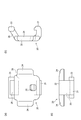
- FIG. 1 It is a perspective view which shows the orthodontic apparatus which concerns on embodiment of this invention. It is a perspective view of the orthodontic apparatus seen from the direction opposite to FIG. It is a figure which shows a cover. It is a sectional side view of the orthodontic apparatus in the obstruction
- an orthodontic appliance is attached to each of a plurality of teeth, an archwire is bridged to each orthodontic appliance, and the archwire gives the orthodontic force to the teeth in the direction of normal dentition.
- the column is corrected.
- FIG. 1 is an exploded perspective view of the orthodontic appliance according to the first embodiment.
- FIG. 2 is a perspective view of the orthodontic appliance shown in FIG. 1 viewed from the opposite direction.
- the orthodontic apparatus shown in FIG. 1 is a type called a bracket
- the present invention can be applied to any type of orthodontic apparatus, such as a buccal tube and a lingual attachment.
- the orthodontic appliance shown in FIG. 1 is a so-called twin bracket type having two sets of wings arranged in parallel, but the present invention is also applicable to a type called a single bracket.
- the present invention may be applied to any of an orthodontic apparatus used on the radial side (labial side) of a patient's teeth and an orthodontic apparatus used on the lingual side (lingual side).
- the orthodontic apparatus 1 includes a base 2, a main body 10, and a cover 20.
- the base 2 has a bottom surface along the shape of the patient's tooth surface to which it is attached.
- the base 2 is attached directly or indirectly to the patient's tooth surface.
- the main body 10 is fixed to the upper surface of the base 2.
- the cover 20 is detachably attached to the main body 10.
- the base 2, the main body 10, and the cover 20 can be formed from metal, ceramics, resin, or the like.
- the side fixed to the tooth surface of the base 2 is the lower side
- the side where the main body 10 of the base 2 is provided is the upper side.
- the slot 3 is provided on the upper surface of the main body 10.
- the slot 3 opens upward.
- the slot 3 is a groove extending in the near centrifugal direction and opening upward.
- the slot 3 is sized to accommodate the archwire.
- the cover 20 is attached to the main body 10 so that the slot 3 can be closed.
- the main body 10 includes a pair of wings provided so as to sandwich the slot 3 in the tooth axis direction. Two pairs of the pair of wings are provided in the near centrifugal direction.
- the main body 10 includes a locking portion 11, a shaft accommodating portion 12, and a rotation restricting portion 13 (see FIG. 2).
- the locking portion 11 is formed on the side of one wing in the tooth axis direction so as to protrude sideways.
- the shaft accommodating part 12 is provided in the other wing of the tooth axis direction among the pair of wings.
- the shaft accommodating portion 12 is provided on the wing opposite to the locking portion 11 in the tooth axis direction of the main body 10.
- the shaft accommodating portion 12 forms a space for rotatably accommodating both end portions of the shaft portion 23 of the cover 20.
- a rotation restricting portion 13 is provided on the upper surface of the main body 10.
- the rotation restricting portion 13 is a step portion provided on the upper surface of the main body 10.
- FIG. 3 is a view showing the cover 20, (a) is a top view, (b) is a side view, and (c) is a front view.
- the cover 20 includes a claw portion 21, a closing portion 22, and a shaft portion 23.
- the closing part 22 is a part capable of closing the opening of the slot 3.
- the blocking part 22 is provided between the claw part 21 and the shaft part 23 in a direction crossing the near-centrifugal direction.
- the blocking portion 22 blocks the opening of the slot 3, thereby preventing the archwire accommodated in the slot 3 from coming out of the opening of the slot 3.
- the blocking part 22 may be a flat plate-shaped part as illustrated, or may be a curved shape, a dome shape, or the like.
- projection part 24 is provided in the both ends of the near-centrifuge direction of the obstruction
- FIG. The projecting portion 24 has substantially the same width as the slot 3 in the near-centrifugal direction.
- stepped portions 16 having a shape corresponding to the protruding portion 24 are provided.
- the step portion 16 may be tapered.
- the claw portion 21 is provided at one end of the cover 20 in the tooth axis direction.
- the claw portion 21 can be locked to the locking portion 11 of the main body 10. As shown in FIG. 3B, the claw portion 21 protrudes downward from the blocking portion 22 and is bent toward the center of the blocking portion 22 at its tip.
- the shaft portion 23 is provided at the end of the cover 20 opposite to the claw portion 21 in the tooth axis direction.
- the shaft portion 23 is a substantially columnar portion extending in the near-centrifugal direction.
- the shaft portion 23 is provided at the tip of a shaft support portion 26 that extends downward from the closing portion 22. As shown in FIG. 2, the length of the shaft portion 23 is larger than the length of the shaft support portion 26 in the near-centrifugal direction. Both end portions of the shaft portion 23 protrude from the shaft support portion 26. The protruding both ends of the shaft portion 23 are accommodated in the shaft accommodating portion 12 of the main body 10.
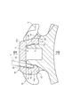
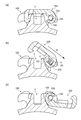
- FIGS. 4 to 6 are side sectional views including the cover 20 and the main body 10.
- FIG. 4 is a side sectional view of the orthodontic appliance 1 in the closed state.
- the closed portion 22 of the cover 20 closes the opening of the slot 3 of the main body 10 while the cover 20 is attached to the main body 10.
- the shaft support portion 26 of the cover 20 is located in the space between the pair of shaft housing portions 12 at the center in the near-centrifugal direction (see FIG. 2).
- the cross-sectional shape of the shaft portion 23 of the cover 20 is a flat shape.
- the cross section of the shaft portion 23 is substantially rectangular.
- the length of the long side a and the short side b of the cross section of the shaft portion 23 is shorter than the inner diameter of the shaft housing portion 12, so that the shaft portion 23 can rotate within the shaft housing portion 12.
- the shaft housing part 12 of the main body 10 communicates with the passage part 15.
- the shaft accommodating portion 12 is connected to an external space via the passage portion 15.
- the inner diameter d of the passage portion 15 is smaller than the long side a of the cross section of the shaft portion 23 and larger than the short side b of the cross section of the shaft portion 23. For this reason, the shaft portion 23 can enter the passage portion 15 only when the short side b of the shaft portion 23 faces the passage portion 15. In the state shown in FIG. 4, the short side b of the cross section of the shaft portion 23 does not face the passage portion 15, and the shaft portion 23 does not enter the passage portion 15.
- a through hole 25 penetrating in the vertical direction is provided in the closing portion 22 of the cover 20.
- the through hole 25 is provided at a position where the locking portion 11 faces the through hole 25 when the cover 20 is closed.
- the locking part 11 is formed with a notch part 14 penetrating to the lower surface on the base 2 side (see FIG. 1).
- a space penetrating from the through hole 25 to the notch portion 14 is formed.
- the penetrated space is inclined so that the lower part is positioned in a direction away from the main body 10 with respect to the vertical direction.
- the practitioner of the orthodontic appliance 1 inserts the rod-shaped release tool T into the space penetrating from the through hole 25 to the notch 14, and at the tip of the release tool T, the nail part 21 of the cover 20 is moved downward and the main body. Press in a direction away from 10. Thereby, the latching
- FIG. 5 is a side sectional view of the orthodontic appliance 1 in an open state.
- the closing portion 22 opens the opening of the slot 3 with the cover 20 attached to the main body 10.
- the claw portion 21 is detached from the locking portion 11, and the cover 20 is rotated clockwise about the shaft portion 23 until the rear end portion 22 a of the closing portion 22 contacts the rotation restricting portion 13.
- the cover 20 is stably supported by the rotation restricting portion 13 of the main body 10 while maintaining the posture in which the rear end portion 22 a of the closing portion 22 is in contact with the rotation restricting portion 13.
- the rotation restricting unit 13 restricts the cover 20 from rotating further clockwise by contacting the cover 20. That is, the rotation restricting unit 13 defines the maximum rotation angle of the cover 20 with respect to the main body 10.
- the short side b of the cross section of the shaft portion 23 does not face the passage portion 15, and the shaft portion 23 does not enter the passage portion 15.
- FIG. 6 is a side sectional view showing a state where the cover 20 is removed from the main body 10. From the state of FIG. 4, the cover 20 is rotated with respect to the main body 10 and the state of FIG. The rotation angle ⁇ of the cover 20 with respect to the main body 10 in FIG. 6 is smaller than the maximum rotation angle shown in FIG.
- the slot 3 can be easily opened and closed by rotating the cover 20 around the shaft portion 23, the archwire can be easily replaced while the orthodontic appliance 1 is attached to the teeth.
- the cover 20 can be easily removed from the main body 10. Since the cover 20 can be easily removed in this manner, the operator can remove the cover 20 and replace it with an optimum cover 20 according to the stage of treatment or according to the site of the tooth to be treated. For example, the cover 20 is removed and replaced with a metal wire or elastic tie, or as described in the next modification, the overhanging portion 24 is inclined toward the bottom of the slot, and the overhanging portion 24 contacts the wire. It can be replaced with a cover with a cutout or a cover without an overhang. In addition, since the cover 20 can be easily removed, the cover 20 and the archwire can be easily cleaned regularly, and the oral cavity can be kept hygienic.
- the shaft portion 23 of the cover 20 is configured to be able to enter the passage portion 15 in a state between the closed state and the maximum open state, and the cover 20 cannot be removed in the closed state and the maximum open state. For this reason, even if the cover 20 is set to the maximum open state in order to replace the archwire, there is no possibility that the cover 20 is unexpectedly removed during the archwire replacement operation and the patient accidentally swallows the cover 20.
- FIG. 7 is a perspective view of the cover 20A of the orthodontic appliance according to the first modification of the present invention.
- the cover 20 ⁇ / b> A includes an overhanging portion 24 ⁇ / b> A that extends from the closing portion 22 ⁇ / b> A so as to incline toward the bottom surface of the slot 3.
- stepped portions 16 having a shape corresponding to the projecting portion 24A are provided.
- the step portion 16 may be tapered.
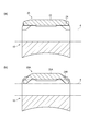
- FIG. 8 is a diagram for explaining the operation of the overhang portions 24 and 24A.
- 8A is a view showing a section VIII-VIII in FIG. 4
- FIG. 8B is a view showing a section similar to FIG. 8A in the orthodontic appliance according to the first modification.
- the two-dot chain line indicates the arch wire 4.
- the overhanging portion 24 extends from the blocking portion 22 substantially in parallel with the bottom surface of the slot 3, and the cover 20 is attached to the archwire 4. There is no contact. For this reason, only when the archwire 4 moves upward and comes into contact with the cover 20, the cover 20 applies a force that pushes the archwire 4 downward.
- This type of orthodontic appliance is called a passive type. In this passive type orthodontic apparatus, since the frictional force generated between the arch wire 4 and the main body 10 is weak, the arch wire 4 can freely slide in the near-distal direction with respect to the orthodontic apparatus. Can move teeth with weak correction force.
- the tip of the overhanging portion 24A protruding downward from the cover 20A is in contact with the archwire 4.
- the overhanging portion 24A can always apply a force that pushes the arch wire 4 toward the bottom surface of the slot.
- the orthodontic apparatus which concerns on the said embodiment is useful, for example when controlling torsion of a tooth correctly.
- This type of orthodontic appliance is called an active type. For example, if the archwire 4 having a larger cross-sectional shape than the internal space defined by the cover 20A and the slot 3 is used, a correction force can always be applied to the main body 10 and the cover 20 from the archwire.
- the archwire 4 inserted into the slot 3 is not limited to the illustrated cross-sectional shape and thickness.
- the optimum archwire 4 is selected according to the treatment and inserted into the slot 3.
- FIG. 9 is a view illustrating a cover 20B of the orthodontic appliance according to the second modification.
- 9A is a top view of the cover 20B of the second modification
- FIG. 9B is a side view
- FIG. 9C is a front view.
- a semicircular cutout 27 is provided at the tip of the overhanging portion 24B of the cover 20B.
- a round wire having a circular cross section is used as an arch wire in a case where the spacing between orthodontic appliances with tight crowding is narrow, the round wire does not contact the overhanging portion 24B due to the notch 27, and the overhanging portion 24B Does not act on the round wire.
- a square wire having a rectangular cross section or the like is used as the arch wire, the square wire comes into contact with the notch 27 or the overhanging portion 24B to apply a force to the square wire.
- the orthodontic appliance can function as an active type and a passive type depending on the type of archwire.
- a notch 27 can be provided in either the active type cover described with reference to FIG. 7 or the passive type cover described with reference to FIGS.
- the shape of the notch 27 is not limited to an arc shape, but may be a rectangular shape or a polygonal shape.
- the length of the overhanging portion 24 in the near-centrifugal direction may be substantially the same as that of the slot 3, may be shorter than the slot 3, or may be longer than the slot 3. Good.
- the protruding length of the overhanging portion 24A from the closing portion 22A may be formed longer than the required length.
- the protruding length of the overhanging portion 24A from the closing portion 22A is set such that the tip of the overhanging portion 24A contacts the bottom surface of the slot 3, and the overhanging portion 24A is adjusted to the thickness of the archwire used for treatment. Can be cut to the required length and used. At this time, it is preferable that a cut portion is shown in the overhanging portion 24A so that a corresponding archwire size can be selected.
- FIG. 10 is a side view of the cover 20C of the third modification.
- a hole forming portion 28 for forming a through hole 25C penetrating in the front-rear direction is provided on the upper surface of the cover 20C of the orthodontic appliance according to Modification 3 shown in FIG.
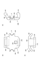
- FIG. 11 is a side sectional view of an orthodontic appliance according to a fourth modification. 11A shows a closed state, FIG. 11B shows a removable state, and FIG. 11C shows an open state.
- the shaft portion 23D is provided in the main body 10D, and the shaft housing portion 12D and the passage portion 15D are provided in the cover 20D.
- the cross section of the shaft portion 23D is flat, and the inner diameter d of the passage portion 15D is set larger than the short side b of the cross section of the shaft portion 23D and smaller than the long side a. For this reason, only when the short side b of the flat shaft portion 23D faces the passage portion 15D, the shaft portion 23D can enter the passage portion 15D. Further, the cover 20D shown in FIG. 11B can be removed from the closed state shown in FIG. 11A until the cover 20D is rotated until the cover 20D reaches the maximum open state shown in FIG.
Landscapes
- Health & Medical Sciences (AREA)
- Oral & Maxillofacial Surgery (AREA)
- Dentistry (AREA)
- Epidemiology (AREA)
- Life Sciences & Earth Sciences (AREA)
- Animal Behavior & Ethology (AREA)
- General Health & Medical Sciences (AREA)
- Public Health (AREA)
- Veterinary Medicine (AREA)
- Dental Tools And Instruments Or Auxiliary Dental Instruments (AREA)
Abstract
L'invention concerne un dispositif de correction de dentition avec une fente pouvant être ouverte, et un couvercle facilement remplacé. Ce dispositif de correction de dentition est équipé d'un couvercle et d'un corps principal, une partie arbre étant fournie au couvercle ou au corps principal, et une partie de réception d'arbre étant fournie à l'autre du couvercle et du corps principal, le couvercle étant fixé rotatif au corps principal via la partie arbre et la partie de réception d'arbre. La partie de réception d'arbre communique avec l'extérieur via une partie passage, et le déplacement de la partie arbre à l'extérieur depuis la partie de réception d'arbre via la partie passage, dans un état entre l'état fermé et l'état d'ouverture maximale, permet de détacher le couvercle du corps principal.
Priority Applications (1)
| Application Number | Priority Date | Filing Date | Title |
|---|---|---|---|
| PCT/JP2015/063809 WO2016181533A1 (fr) | 2015-05-13 | 2015-05-13 | Dispositif de correction de dentition |
Applications Claiming Priority (1)
| Application Number | Priority Date | Filing Date | Title |
|---|---|---|---|
| PCT/JP2015/063809 WO2016181533A1 (fr) | 2015-05-13 | 2015-05-13 | Dispositif de correction de dentition |
Publications (1)
| Publication Number | Publication Date |
|---|---|
| WO2016181533A1 true WO2016181533A1 (fr) | 2016-11-17 |
Family
ID=57247946
Family Applications (1)
| Application Number | Title | Priority Date | Filing Date |
|---|---|---|---|
| PCT/JP2015/063809 Ceased WO2016181533A1 (fr) | 2015-05-13 | 2015-05-13 | Dispositif de correction de dentition |
Country Status (1)
| Country | Link |
|---|---|
| WO (1) | WO2016181533A1 (fr) |
Citations (6)
| Publication number | Priority date | Publication date | Assignee | Title |
|---|---|---|---|---|
| US4077126A (en) * | 1976-07-06 | 1978-03-07 | Pletcher Erwin Carroll | Orthodontic bracket |
| US4559012A (en) * | 1984-12-06 | 1985-12-17 | Pletcher Erwin Carroll | Orthodontic bracket |
| US20080057459A1 (en) * | 2006-08-31 | 2008-03-06 | Norbert Abels | Lifestyle bracket system having interchangeable ligation covers |
| WO2010103153A1 (fr) * | 2009-03-12 | 2010-09-16 | Orthodontic World Institute Jose Duran Von Arx, S.L. | Support pour pièces dentaires et procédé permettant d'augmenter et/ou de réduire le frottement d'éléments de tension dans des supports orthodontiques |
| US20110183280A1 (en) * | 2010-01-25 | 2011-07-28 | Mr. Christopher C. Cosse | Orthodontic appliance systems |
| US20140212828A1 (en) * | 2012-10-09 | 2014-07-31 | Dentsply International Inc. | Self-ligating orthodontic brackets |
-
2015
- 2015-05-13 WO PCT/JP2015/063809 patent/WO2016181533A1/fr not_active Ceased
Patent Citations (6)
| Publication number | Priority date | Publication date | Assignee | Title |
|---|---|---|---|---|
| US4077126A (en) * | 1976-07-06 | 1978-03-07 | Pletcher Erwin Carroll | Orthodontic bracket |
| US4559012A (en) * | 1984-12-06 | 1985-12-17 | Pletcher Erwin Carroll | Orthodontic bracket |
| US20080057459A1 (en) * | 2006-08-31 | 2008-03-06 | Norbert Abels | Lifestyle bracket system having interchangeable ligation covers |
| WO2010103153A1 (fr) * | 2009-03-12 | 2010-09-16 | Orthodontic World Institute Jose Duran Von Arx, S.L. | Support pour pièces dentaires et procédé permettant d'augmenter et/ou de réduire le frottement d'éléments de tension dans des supports orthodontiques |
| US20110183280A1 (en) * | 2010-01-25 | 2011-07-28 | Mr. Christopher C. Cosse | Orthodontic appliance systems |
| US20140212828A1 (en) * | 2012-10-09 | 2014-07-31 | Dentsply International Inc. | Self-ligating orthodontic brackets |
Similar Documents
| Publication | Publication Date | Title |
|---|---|---|
| JP7828306B2 (ja) | 非滑り歯列弓形態を伴う歯列矯正器具 | |
| US10485636B2 (en) | Orthodontic bracket | |
| JP6391681B2 (ja) | 回転可能クロージャ部材を有する自動結紮型歯科矯正ブラケット | |
| JP4555375B2 (ja) | 舌側ブラケット | |
| JP5038329B2 (ja) | 歯列不正を処置するための歯列矯正デバイスおよび方法 | |
| CN103108603B (zh) | 齿列矫正托架 | |
| JP5415612B2 (ja) | 自己結紮式歯列矯正ブラケット | |
| JP4607020B2 (ja) | 自己結紮歯科矯正ブラケット | |
| JP7153571B2 (ja) | 自己結紮式歯科矯正用ブラケット | |
| CN101636123A (zh) | 正牙植入物盖以及包括其的正牙治疗组件 | |
| CN104812328B (zh) | 自锁正畸托槽 | |
| JP2015531303A5 (fr) | ||
| JP2012515067A (ja) | 転位歯を矯正する歯科矯正ブラケットおよび方法 | |
| JP2009285517A (ja) | 歯科矯正ブラケット及び器具、並びに歯科矯正ブラケットを作成及び使用する方法 | |
| US20090061376A1 (en) | Self-Locking Orthodontic Bracket | |
| US11007038B2 (en) | Apparatus for achieving molar distalization | |
| EP3284436B1 (fr) | Bracket orthodontique | |
| US7186114B2 (en) | Self-ligating lingual orthodontic bracket | |
| EP2392288B1 (fr) | Dispositif de ligature de fils orthodontiques | |
| ES2986740T3 (es) | Bracket ortodóncico con puerta de ligadura móvil | |
| US20190090990A1 (en) | Orthodontic bracket | |
| JP5139392B2 (ja) | 歯列矯正用具 | |
| US20170014207A1 (en) | Self-ligating orthodontic brace and set comprising a plurality of such braces | |
| JPWO2020162172A1 (ja) | 歯科矯正用のブラケット | |
| WO2016181533A1 (fr) | Dispositif de correction de dentition |
Legal Events
| Date | Code | Title | Description |
|---|---|---|---|
| 121 | Ep: the epo has been informed by wipo that ep was designated in this application |
Ref document number: 15891857 Country of ref document: EP Kind code of ref document: A1 |
|
| NENP | Non-entry into the national phase |
Ref country code: DE |
|
| 122 | Ep: pct application non-entry in european phase |
Ref document number: 15891857 Country of ref document: EP Kind code of ref document: A1 |
|
| NENP | Non-entry into the national phase |
Ref country code: JP |