WO2016181572A1 - 分注システム、コントローラ及び制御方法 - Google Patents
分注システム、コントローラ及び制御方法 Download PDFInfo
- Publication number
- WO2016181572A1 WO2016181572A1 PCT/JP2015/071887 JP2015071887W WO2016181572A1 WO 2016181572 A1 WO2016181572 A1 WO 2016181572A1 JP 2015071887 W JP2015071887 W JP 2015071887W WO 2016181572 A1 WO2016181572 A1 WO 2016181572A1
- Authority
- WO
- WIPO (PCT)
- Prior art keywords
- position information
- tip
- dispenser
- image
- liquid
- Prior art date
- Legal status (The legal status is an assumption and is not a legal conclusion. Google has not performed a legal analysis and makes no representation as to the accuracy of the status listed.)
- Ceased
Links
Images


Classifications
-
- G—PHYSICS
- G01—MEASURING; TESTING
- G01N—INVESTIGATING OR ANALYSING MATERIALS BY DETERMINING THEIR CHEMICAL OR PHYSICAL PROPERTIES
- G01N35/00—Automatic analysis not limited to methods or materials provided for in any single one of groups G01N1/00 - G01N33/00; Handling materials therefor
- G01N35/10—Devices for transferring samples or any liquids to, in, or from, the analysis apparatus, e.g. suction devices, injection devices
- G01N35/1009—Characterised by arrangements for controlling the aspiration or dispense of liquids
- G01N35/1011—Control of the position or alignment of the transfer device
-
- B—PERFORMING OPERATIONS; TRANSPORTING
- B01—PHYSICAL OR CHEMICAL PROCESSES OR APPARATUS IN GENERAL
- B01L—CHEMICAL OR PHYSICAL LABORATORY APPARATUS FOR GENERAL USE
- B01L3/00—Containers or dishes for laboratory use, e.g. laboratory glassware; Droppers
- B01L3/02—Burettes; Pipettes
- B01L3/021—Pipettes, i.e. with only one conduit for withdrawing and redistributing liquids
- B01L3/0217—Pipettes, i.e. with only one conduit for withdrawing and redistributing liquids of the plunger pump type
- B01L3/0237—Details of electronic control, e.g. relating to user interface
-
- B—PERFORMING OPERATIONS; TRANSPORTING
- B25—HAND TOOLS; PORTABLE POWER-DRIVEN TOOLS; MANIPULATORS
- B25J—MANIPULATORS; CHAMBERS PROVIDED WITH MANIPULATION DEVICES
- B25J15/00—Gripping heads and other end effectors
- B25J15/0019—End effectors other than grippers
-
- B—PERFORMING OPERATIONS; TRANSPORTING
- B25—HAND TOOLS; PORTABLE POWER-DRIVEN TOOLS; MANIPULATORS
- B25J—MANIPULATORS; CHAMBERS PROVIDED WITH MANIPULATION DEVICES
- B25J9/00—Program-controlled manipulators
- B25J9/0084—Program-controlled manipulators comprising a plurality of manipulators
- B25J9/0087—Dual arms
-
- B—PERFORMING OPERATIONS; TRANSPORTING
- B25—HAND TOOLS; PORTABLE POWER-DRIVEN TOOLS; MANIPULATORS
- B25J—MANIPULATORS; CHAMBERS PROVIDED WITH MANIPULATION DEVICES
- B25J9/00—Program-controlled manipulators
- B25J9/16—Program controls
- B25J9/1679—Program controls characterised by the tasks executed
- B25J9/1684—Tracking a line or surface by means of sensors
-
- B—PERFORMING OPERATIONS; TRANSPORTING
- B25—HAND TOOLS; PORTABLE POWER-DRIVEN TOOLS; MANIPULATORS
- B25J—MANIPULATORS; CHAMBERS PROVIDED WITH MANIPULATION DEVICES
- B25J9/00—Program-controlled manipulators
- B25J9/16—Program controls
- B25J9/1694—Program controls characterised by use of sensors other than normal servo-feedback from position, speed or acceleration sensors, perception control, multi-sensor controlled systems, sensor fusion
- B25J9/1697—Vision controlled systems
-
- C—CHEMISTRY; METALLURGY
- C12—BIOCHEMISTRY; BEER; SPIRITS; WINE; VINEGAR; MICROBIOLOGY; ENZYMOLOGY; MUTATION OR GENETIC ENGINEERING
- C12M—APPARATUS FOR ENZYMOLOGY OR MICROBIOLOGY; APPARATUS FOR CULTURING MICROORGANISMS FOR PRODUCING BIOMASS, FOR GROWING CELLS OR FOR OBTAINING FERMENTATION OR METABOLIC PRODUCTS, i.e. BIOREACTORS OR FERMENTERS
- C12M1/00—Apparatus for enzymology or microbiology
-
- G—PHYSICS
- G01—MEASURING; TESTING
- G01N—INVESTIGATING OR ANALYSING MATERIALS BY DETERMINING THEIR CHEMICAL OR PHYSICAL PROPERTIES
- G01N35/00—Automatic analysis not limited to methods or materials provided for in any single one of groups G01N1/00 - G01N33/00; Handling materials therefor
- G01N35/0099—Automatic analysis not limited to methods or materials provided for in any single one of groups G01N1/00 - G01N33/00; Handling materials therefor comprising robots or similar manipulators
-
- Y—GENERAL TAGGING OF NEW TECHNOLOGICAL DEVELOPMENTS; GENERAL TAGGING OF CROSS-SECTIONAL TECHNOLOGIES SPANNING OVER SEVERAL SECTIONS OF THE IPC; TECHNICAL SUBJECTS COVERED BY FORMER USPC CROSS-REFERENCE ART COLLECTIONS [XRACs] AND DIGESTS
- Y10—TECHNICAL SUBJECTS COVERED BY FORMER USPC
- Y10S—TECHNICAL SUBJECTS COVERED BY FORMER USPC CROSS-REFERENCE ART COLLECTIONS [XRACs] AND DIGESTS
- Y10S901/00—Robots
- Y10S901/02—Arm motion controller
- Y10S901/09—Closed loop, sensor feedback controls arm movement
-
- Y—GENERAL TAGGING OF NEW TECHNOLOGICAL DEVELOPMENTS; GENERAL TAGGING OF CROSS-SECTIONAL TECHNOLOGIES SPANNING OVER SEVERAL SECTIONS OF THE IPC; TECHNICAL SUBJECTS COVERED BY FORMER USPC CROSS-REFERENCE ART COLLECTIONS [XRACs] AND DIGESTS
- Y10—TECHNICAL SUBJECTS COVERED BY FORMER USPC
- Y10S—TECHNICAL SUBJECTS COVERED BY FORMER USPC CROSS-REFERENCE ART COLLECTIONS [XRACs] AND DIGESTS
- Y10S901/00—Robots
- Y10S901/30—End effector
-
- Y—GENERAL TAGGING OF NEW TECHNOLOGICAL DEVELOPMENTS; GENERAL TAGGING OF CROSS-SECTIONAL TECHNOLOGIES SPANNING OVER SEVERAL SECTIONS OF THE IPC; TECHNICAL SUBJECTS COVERED BY FORMER USPC CROSS-REFERENCE ART COLLECTIONS [XRACs] AND DIGESTS
- Y10—TECHNICAL SUBJECTS COVERED BY FORMER USPC
- Y10S—TECHNICAL SUBJECTS COVERED BY FORMER USPC CROSS-REFERENCE ART COLLECTIONS [XRACs] AND DIGESTS
- Y10S901/00—Robots
- Y10S901/46—Sensing device
- Y10S901/47—Optical
Definitions
- the present disclosure relates to a dispensing system, a controller, and a control method.
- Patent Document 1 discloses a chip, a liquid feeding device that sucks a sample into the chip or discharges a sample in the chip, a chip transport mechanism, a detection unit that detects the liquid level of the sample, A supply / discharge robot including a liquid feeding power device and a control device for controlling the chip transport mechanism so that the tip end and the sample liquid level are kept in contact with each other based on the liquid level position of the sample during aspiration. It is disclosed.
- This disclosure is intended to provide a dispensing system, a dispensing method, a control device, and a control method capable of performing a more reliable dispensing operation.
- a dispensing system includes a robot that moves a dispenser for sucking a liquid to be dispensed, at least a tip of the dispenser, a liquid level, and a lower level than the liquid level.
- the image processing unit that acquires the position information of the tip of the injection device, and the position information of the tip, the position information of the liquid surface, and the position information of the boundary when the liquid is sucked into the dispenser And a descent controller that controls the robot to lower the dispenser.
- a dispensing system includes a robot that moves a dispenser for sucking a liquid to be dispensed, at least a tip of the dispenser, a liquid level, and a lower level than the liquid level.
- a camera for capturing an image including a non-dispensing object that is positioned, and based on the image, position information on the liquid level, position information on a boundary between the liquid and the non-dispensing object, and dispensing Obtaining the position information of the tip of the injection device, when sucking the liquid into the dispenser, based on the position information of the tip, the position information of the liquid level, and the position information of the boundary, And a circuit configured to perform control of the robot to lower the dispenser.
- the controller according to the present disclosure is based on an image including at least a tip of a dispenser for sucking a liquid to be dispensed, a liquid level of the liquid, and a non-dispensing target positioned below the liquid level.
- An image processing unit for acquiring position information on the liquid level, position information on the boundary between the liquid and the non-dispensing object, and position information on the tip of the dispenser; and the liquid in the dispenser And a descent controller that controls the robot to lower the dispenser based on the position information on the tip, the position information on the liquid level, and the position information on the boundary.
- the control method includes an image including at least a tip portion of a dispenser for sucking a liquid to be dispensed, a liquid level of the liquid, and a non-dispensing target positioned below the liquid level.
- an image including at least a tip portion of a dispenser for sucking a liquid to be dispensed, a liquid level of the liquid, and a non-dispensing target positioned below the liquid level.
- FIG. 25 is a perspective view illustrating a state where the robot is operating the rack in FIG. 24. It is a schematic diagram which shows the structure of the dispensing system which concerns on 2nd embodiment. It is a functional block diagram of a robot control unit and an image processing unit.
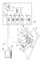
- the dispensing system 1 is for performing a dispensing operation for selectively taking out the liquid stored in the container 90.
- the container 90 accommodates an object to be worked by the dispensing system 1.
- the container 90 is formed of a material that can transmit visible light or light of a specific wavelength.
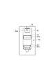
- the container 90 is a microtube, for example, and has a cylindrical side wall 91 and a bottom 92 (see FIGS. 2A and 2B).
- the lower portion 91a of the side wall 91 has a tapered shape that narrows toward the bottom 92 side.
- the container 90 is not limited to such a microtube, and may have any shape as long as it can accommodate an object and can transmit visible light or light of a specific wavelength.
- the object accommodated in the container 90 is separated into the liquid C1 to be dispensed and the non-dispensing object C2 by centrifugation or the like, and the liquid C1 forms the liquid surface SF1, and the non-dispensing object C2 Is located below the liquid level SF1.
- the non-dispensing object C2 include a solid precipitate or a liquid separated from the liquid C1.
- the boundary part BD1 between the liquid C1 and the non-dispensing object C2 is parallel to the liquid surface SF1 (see FIG. 2A).
- the boundary part BD1 may be inclined with respect to the liquid level SF1 (see FIG. 2B).
- the boundary part BD1 is visible from the outside of the container 90. For example, if the transmissivity of light that can pass through the container 90 is different between the liquid C1 and the non-dispensing object C2, the boundary portion BD1 becomes visible. Even if the refractive index of the light that can pass through the container 90 is different between the liquid C1 and the non-dispensing object C2, the boundary portion BD1 becomes visible.
- the dispensing system 1 takes out the liquid C1 to be dispensed from the container 90 in a state where the non-dispensing object C2 remains in the container 90, and transfers it to another container 90.
- the non-dispensing object C2 is merely a “non-dispensing object” in the process of dispensing the liquid C1.
- the dispensing system 1 may further dispense the non-dispensing object C2 itself in the step after dispensing the liquid C1.
- each component of the dispensing system 1 will be described.
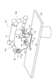
- the dispensing system 1 includes a robot 10 and a camera 43.
- the robot 10 is used for operations such as moving the dispenser 30.
- the dispenser 30 aspirates the liquid C1 to be dispensed.
- Examples of the dispenser 30 include an electric pipette or syringe that automatically sucks and discharges a liquid by a specific signal or a specific operation.
- the dispenser 30 may not be motorized, and may be a manual syringe or pipette, for example. In this case, as described later, the dispenser 30 may be operated by both arms of the double-armed robot 10.
- the dispenser 30 may be anything as long as it can suck the liquid C1, but the following illustrates a case where the dispenser 30 is an electric pipette.
- the dispenser 30 has a main body 31 and a chip 32.
- the main body 31 incorporates an electric pump, for example, and operates according to a command input.
- the chip 32 is detachably attached to the main body 31.
- the tip 32 has, for example, a pointed cylindrical shape and forms the distal end portion 30 a of the dispenser 30.
- the dispenser 30 decompresses the inside of the chip 32 by the main body 31, thereby sucking the liquid from the tip 30a and pressurizing the inside of the chip 32 to discharge the liquid from the tip 30a.
- the robot 10 may be anything as long as the operation of moving the dispenser 30 can be performed.
- the robot 10 may be a single arm type or a double arm type.
- FIG. 1 illustrates a double-armed robot 10.
- the robot 10 includes a trunk portion 11, a shoulder portion 12, a first arm 13A, and a second arm 13B.
- drum 11 stands with respect to a floor surface.
- the shoulder portion 12 is attached to the upper portion of the trunk portion 11 and is rotatable around a vertical axis.
- the arms 13A and 13B are, for example, serial link type articulated arms, and are attached to both ends of the shoulder portion 12, respectively.
- a gripping mechanism 14 is provided at the ends of the arms 13A and 13B.
- the gripping mechanism 14 is a robot hand having a plurality of finger portions 15, for example, and grips various work objects by opening and closing the finger portions 15.
- the camera 43 captures an image including at least the tip portion 30a of the dispenser 30, the liquid surface SF1 of the liquid C1, and the non-dispensing object C2.
- the camera 43 has an image pickup device such as a CCD (Charge Coupled Device) image sensor or a CMOS (Complementary Metal Oxide Semiconductor) image sensor, picks up an image in response to a command input, and outputs the image data.
- CCD Charge Coupled Device
- CMOS Complementary Metal Oxide Semiconductor
- the dispensing system 1 may further include a table 20.
- the table 20 is attached to the robot 10 and supports an object to be worked by the robot 10.
- the dispensing system 1 may further include a rack 40 having the camera 43 as a constituent element.
- the rack 40 includes a stage 41, a container holding unit 44, and a camera 43.
- the stage 41 is, for example, a rectangular plate (support plate), and is disposed on the table 20 in a tiltable state.
- the stage 41 may be anything as long as it does not substantially deform (except for slight deformation caused by bending of the constituent material).
- the stage 41 may be a block or a frame assembly.
- the container holding unit 44 is fixed to the stage 41 and holds the container 90.
- the container holding unit 44 is provided on the upper surface side of the plate-like stage 41, and holds the container 90 so that the side wall 91 is perpendicular to the upper surface.
- the camera 43 is fixed to the stage 41 at a position where the container 90 can be imaged.
- the camera 43 is arranged such that its central axis CL2 (optical axis of the optical system) passes through the container 90, and is fixed to a column 42 (camera holding portion 41a) protruding from the upper surface of the stage 41.
- the camera holding unit 41a captures an image including at least a part of the liquid level SF1 of the liquid C1 in the container 90, at least a part of the non-dispensing object C2, and the tip part 30a inserted into the container 90.
- the camera 43 is held in a possible posture.
- the rack 40 may further include a stage holding unit 50.
- the stage holding unit 50 holds the stage 41 so as to be rotatable around an axis Ax1 (first axis) along the direction in which the container holding unit 44 and the camera 43 are arranged.
- the stage holding unit 50 includes a support plate 51 and a hinge 52.
- the support plate 51 is, for example, a rectangular plate.
- the hinge 52 connects the stage 41 and the support plate 51 so as to be rotatable with respect to each other along one side along the axis Ax1. Thereby, the stage 41 can rotate around the axis Ax1.
- the support plate 51 is disposed on the table 20 such that the stage 41 overlaps the support plate 51 and the hinge 52 is positioned on the opposite side of the robot 10, for example.
- the support plate 51 may be fixed to the table 20 by bolt fastening or the like. Even if the support plate 51 is fixed to the table 20, the stage 41 can rotate about the axis Ax1.
- the rack 40 may further include a handle 46.
- the handle 46 is provided on the opposite side of the hinge 52 on the stage 41, for example.
- the handle 46 is positioned on the robot 10 side.
- the handle 46 protrudes from the upper surface of the stage 41, and the upper part 46 a protrudes to the opposite side of the hinge 52.
- tilt the rack 40 means that the object to be held in the rack 40 is tilted by tilting a part or the whole of the rack 40.
- the rack 40 may further include an angle holding mechanism 60.
- the angle holding mechanism 60 holds the tilt angle after the stage 41 is tilted by the robot 10.
- the angle holding mechanism 60 has a stopper 61.
- the stopper 61 is provided on the support plate 51 on the opposite side of the hinge 52.
- the stopper 61 protrudes from the upper surface of the support plate 51, and the upper portion 61 a projects to the opposite side of the hinge 52.
- the stopper 61 has a groove 61b facing the hinge 52 side. The edge of the stage 41 can be fitted into the groove 61b.
- the stopper 61 is rotatable so as to bring the groove 61b close to and away from the hinge 52.
- the base of the stopper 61 is connected to the support plate 51 via a hinge 62 parallel to the hinge 52.
- the stage 41 is restrained when the stopper 61 is tilted toward the hinge 52 while the stage 41 is rotated and the edge of the stage 41 is fitted into the groove 61b. Thereby, the inclination angle of the stage 41 is maintained.
- the dispensing system 1 may further include a light 45.
- the light 45 irradiates the container 90 held by the container holding unit 44 with light.
- the light 45 irradiates at least an imaging range by the camera 43.
- the light irradiated by the light 45 only needs to be able to pass through the container 90 and be detected by the camera 43.
- the light 45 may emit red visible light.
- Examples of the light source of the light 45 include an LED (Light Emitting Diode).
- the light 45 may be fixed to the stage 41 and form a part of the rack 40. That is, the rack 40 may further include the light 45. In this case, the light 45 may be fixed to the stage 41 in such a manner that the container 90 is sandwiched between the light 45 and the camera 43. That is, the container holding part 44 may be located between the camera 43 and the light 45. For example, the light 45 is held by a portion of the stage 41 that sandwiches the container holding portion 44 between the camera holding portion 41a (light holding portion 41b). The light holding part 41b holds the light 45 in a posture that emits light toward the container 90 side.
- the dispensing system 1 further includes a controller 100.
- the controller 100 acquires at least the position information of the liquid level SF1, the position information of the boundary part BD1, and the position information of the tip part 30a of the dispenser 30 based on the image captured by the camera 43.
- the dispenser 30 is lowered based on the position information of the distal end portion 30a, the position information of the liquid surface SF1, and the position information of the boundary portion BD1.
- Controlling the robot 10 is configured to execute.
- the controller 100 may have a console 200 as a user interface.
- the console 200 includes a monitor 201 and an input device 202 such as a keyboard.
- the console 200 may be a touch panel in which a monitor and an input device are integrated.
- the controller 100 may be of any type as long as it is configured to execute the above-described processing. Hereinafter, the configuration of the controller 100 will be described in detail with reference to FIGS. 1 and 5 to 7. Illustrate.
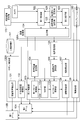
- the controller 100 includes, as function modules, a protocol construction unit 110, an image processing unit 120, a backlight control unit 160, a robot control unit 130, a dispenser control unit 140, a process storage unit 151, and a reference data storage. Part 152.
- the protocol construction unit 110 sets work processes of the robot 10 including a plurality of types of dispensing operations, registers them in the process storage unit 151, and registers reference data for dispensing operations in the reference data storage unit 152.
- the reference data is data necessary for controlling the robot 10 and includes image processing data.
- the image processing data includes, for example, an image pattern for image recognition.
- the image processing unit 120 is based on the position information of the liquid surface SF1, the position information of the boundary BD1, and the position of the tip 30a. Get information and.
- the backlight control unit 160 switches the light 45 on and off. For example, the backlight control unit 160 turns off the backlight in at least a part of the time period when the imaging by the camera 43 is not performed. This can reduce the burden on the operator's eyes.
- the robot control unit 130 controls the robot 10 based on the position information acquired by the image processing unit 120 and the work process registered in the process storage unit 151.
- the dispenser control unit 140 controls the dispenser 30 in synchronization with the control of the robot 10 based on the work process registered in the process storage unit 151. For example, when the dispenser 30 is an electric type, the dispenser control unit 140 turns suction by the dispenser 30 on and off. The dispenser control unit 140 may control the robot 10 so as to operate an on / off switch of the dispenser 30 instead of controlling the dispenser 30 itself. Moreover, when the dispenser 30 is a manual type, the dispenser control part 140 may control the robot 10 so that the dispenser 30 may be operated.
- the dispenser control unit 140 grips the outer cylinder of the syringe by one of the arms 13A and 13B, and the plunger of the syringe by the other of the arms 13A and 13B.
- the robot 10 may be controlled to push and pull.
- the protocol construction unit 110 includes a process setting unit 111, a process confirmation unit 114, an interrupt unit 112, and a reference data registration unit 113.
- the process setting unit 111 sets a work process of the robot 10 including a plurality of types of dispensing work. Specifically, the process setting unit 111 acquires a work process of the robot 10 including a plurality of types of dispensing work from the console 200 and registers it in the process storage unit 151. Thus, the console 200 functions as a user interface for registering work processes.
- the process confirmation unit 114 confirms the work content that the robot control unit 130 intends to execute.
- the interrupting unit 112 stops the robot 10 via the robot control unit 130 when the robot 10 tries to perform a dispensing operation in which the reference data is not registered, and the robot 10 operates after the registration of the reference data. To resume.
- the reference data registration unit 113 displays a reference data setting screen on the console 200 when the interrupt unit 112 stops the robot 10, and acquires and registers the reference data from the console 200.
- the console 200 also functions as a user interface for registering reference data.
- the robot control unit 130 includes a container arrangement control unit 131, a dispenser arrangement control unit 132, a descent control unit 133, a reference distance setting unit 134, a boundary monitoring unit 135, a target position.
- a setting unit 136, a tilt detection unit 137, and a tilt control unit 138 are included.
- the container arrangement control unit 131 controls the robot 10 to arrange the container 90 within the field of view of the camera 43.
- the container arrangement control unit 131 controls the arm 13 ⁇ / b> B so that the container 90 is arranged on the container holding unit 44.
- the dispenser arrangement control unit 132 controls the arm 13A so as to arrange the dispenser 30 at the starting position of suction or discharge.
- the dispenser 30 When the descent controller 133 sucks the liquid C1 into the dispenser 30, the dispenser 30 is based on the position information of the tip 30a, the position information of the liquid C1, and the position information of the boundary BD1. The robot 10 is controlled to move down.
- the descent control unit 133 includes a first mode control unit 133a, a second mode control unit 133b, and a switching unit 133c.
- the first mode control unit 133a controls the robot 10 so as to lower the tip portion 30a following the lowering of the liquid C1.
- the second mode control unit 133b controls the robot 10 to lower the tip 30a to the final target position.
- the final target position is set in advance based on the position information of the boundary portion BD1.
- the switching unit 133c switches the control by the first mode control unit 133a to the control by the second mode control unit 133b in response to the leading end 30a approaching the final target position.
- the switching unit 133c controls the first mode control unit 133a according to the second mode control unit 133b as the distance from the tip 30a to the final target position becomes smaller than a preset reference distance. Switch to control by.
- the reference distance setting unit 134 sets the reference distance.
- the boundary monitoring unit 135 detects a change in the boundary portion BD1 based on the image captured by the camera 43.
- the target position setting unit 136 sets the final target position based on the position information of the boundary part BD1.
- the inclination detecting unit 137 detects the inclination of the boundary part BD1 with respect to the liquid surface SF1 based on the image captured by the camera 43. Note that the inclination of the boundary portion BD1 with respect to the liquid level SF1 may occur when the container 90 is upright and the central axis is vertical in a state where the boundary portion BD1 is inclined with respect to the central axis of the container 90.
- the tilt control unit 138 controls the robot 10 so that the container 90 is tilted in a direction in which the boundary portion BD1 is inclined gently with respect to the liquid level SF1.
- the inclination controller 138 moves the container 90 and the dispenser 30 to the boundary part BD1 as the tip part 30a approaches the final target position.
- the robot 10 may be controlled so as to be tilted in a direction in which the tilt of the robot becomes gentle.
- the hardware of the controller 100 is not necessarily divided into the functional blocks described above.
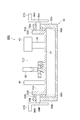
- a hardware configuration of the controller 100 for example, a circuit having a processor 101, a memory 102, a storage 103, an input / output port 104, and a driver 105 can be cited as shown in FIG.
- the driver 105 is a circuit for controlling the actuator of the robot 10.
- the input / output port 104 inputs / outputs data between the camera 43 and the console 200, outputs a suction or discharge on / off command to the dispenser 30, and sends a drive command for the actuator of the robot 10 to the driver 105. Output.
- the processor 101 configures each function of the controller 100 described above by executing a program in cooperation with at least one of the memory 102 and the storage 103.
- the console 200 and the controller 100 may be integrated on the hardware or may be separated from each other.
- the controller 100 may be divided into a plurality of hardware.
- the separated hardware may be connected by either wire or wireless, and there is no limitation on the connection method.
- the circuit of the controller 100 acquires the position information of the liquid surface SF1, the position information of the boundary portion BD1, and the position information of the tip portion 30a based on the image captured by the camera 43, and the liquid C1. Is sucked into the dispenser 30, the robot 10 is caused to lower the dispenser 30 based on the position information of the tip 30 a, the position information of the liquid level SF 1, and the position information of the boundary BD 1. Is configured to perform the control.
- the hardware configuration of the controller 100 is not necessarily limited to that configuring each functional module by executing a program.
- the controller 100 may constitute each function by a dedicated logic circuit or an ASIC (Application Specific Integrated Circuit) in which the controller 100 is integrated.
- ASIC Application Specific Integrated Circuit
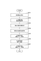
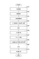
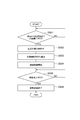
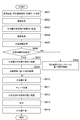
- step S101 the process setting unit 111 sets a work process of the robot 10 including a plurality of types of dispensing work.
- the process setting unit 111 acquires a work process of the robot 10 including a plurality of types of dispensing work from the console 200 and registers it in the process storage unit 151.
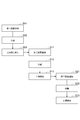
- FIG. 9 is a diagram illustrating an example of setting work processes.
- This work process includes steps S01 to S23.
- Step S01 is a step of injecting the first reagent into the first container 90 containing a sample such as a cell, and stirring the contents of the container 90 by, for example, a vortex mixer.
- Step S02 is a step of separating the contents of the first container 90 into the liquid C1 to be dispensed and the non-dispensing object C2 by centrifugation or the like.
- Step S03 is a step of taking out the liquid C1 to be dispensed in the first container 90 and transferring it to the second container 90.
- Step S11 is a step of injecting the second reagent into the second container 90 containing the liquid C1, and stirring the contents of the container 90 by, for example, a vortex mixer.
- Step S12 is a step of separating the contents of the second container 90 into the liquid C1 to be dispensed and the non-dispensing object C2 by centrifugation or the like.
- Step S13 is a step of discharging the liquid C1 to be dispensed in the second container 90.
- Step S21 is a step of injecting the third reagent into the second container 90 containing the remaining non-dispensing object C2, and stirring the contents of the container 90 by, for example, a vortex mixer.
- Step S22 is a step of separating the contents of the second container 90 into the liquid C1 to be dispensed and the non-dispensing object C2 by centrifugation or the like.
- Step S23 is a step of discharging the liquid C1 to be dispensed in the second container 90 and collecting the non-dispensing object C2 remaining in the container 90.
- steps S03, S13, and S23 correspond to the dispensing work.
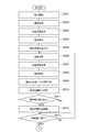
- step S102 the robot control unit 130 controls the robot 10 to start execution of the process set in step S101.
- the robot control unit 130 executes step S102 in response to, for example, a command input by the user.
- step S103 the process confirmation unit 114 confirms whether or not the process to be executed is a dispensing operation.
- the controller 100 executes step S114.
- step S114 the robot control unit 130 controls the robot 10 to execute the process.
- step S115 the controller 100 proceeds with the process to step S115 described later.
- step S ⁇ b> 104 the robot control unit 130 controls the arm 13 ⁇ / b> B so that the container 90 is disposed on the container holding unit 44.
- the robot control unit 130 controls the arm 13B so as to remove the cap.
- step S105 the robot control unit 130 controls the arm 13A so as to start conveying the dispenser 30 to the container 90 side.
- step S106 the controller 100 executes step S106.
- step S ⁇ b> 106 the interrupt unit 112 checks whether or not the reference data for the dispensing work to be executed is registered in the reference data storage unit 152. If it is determined that the reference data is registered, the controller 100 advances the process to step S112 described later.
- step S ⁇ b> 107 the interrupt unit 112 acquires an image from the camera 43.
- step S108 based on the image acquired in step S107, the interrupt unit 112 determines whether or not the distal end portion 30a has reached the reference data registration position.
- the reference data registration position means a position that falls within the field of view of the camera 43 above the liquid level SF1.
- the interrupt unit 112 repeats steps S107 and S108 until the tip 30a reaches the reference data registration position.
- step S109 If it is determined in step S108 that the tip 30a has reached the reference data registration position, the controller 100 executes step S109.
- step S ⁇ b> 109 the interrupt unit 112 outputs a command to stop the transport of the dispenser 30 to the robot control unit 130.
- the robot control unit 130 controls the robot 10 to stop the transport of the dispenser 30 in response to a command from the interrupt unit 112.
- the interrupt unit 112 stops the robot 10 after the tip 30a enters the field of view of the camera 43 when the reference data is not registered.
- step S110 the reference data registration unit 113 performs registration of reference data.
- step S ⁇ b> 111 the interrupt unit 112 outputs a command for resuming conveyance of the dispenser 30 to the robot control unit 130.
- the robot control unit 130 controls the robot 10 so as to resume conveyance of the dispenser 30 in response to a command from the interrupt unit 112.
- the reference data registration unit 113 performs registration of the reference data when the interrupt unit 112 stops the robot 10, and the interrupt unit 112 resumes the operation of the robot 10 after the registration of the reference data.
- step S112 the robot control unit 130 controls the arm 13A so as to place the dispenser 30 at the suction start position.
- the starting position of the suction is set in advance at a position having a predetermined depth from the liquid level SF1, for example.
- step S113 the robot controller 130 and the dispenser controller 140 respectively control the robot 10 and the dispenser 30 so as to execute the dispensing operation.
- step S115 the robot control unit 130 determines whether or not the execution of all processes has been completed. When it is determined that the execution of all the processes has not been completed, the controller 100 executes Step S116. In step S116, the reference data registration unit 113 shifts the execution target to the next step. Thereafter, the controller 100 returns the process to step S103. Thereby, stopping the robot 10 when the reference data is not registered is executed by the interrupt unit 112 for each dispensing operation. Each time the interrupt unit 112 stops the robot 10, the reference data registration unit 113 executes registration of reference data corresponding to the dispensing operation scheduled to be executed next.
- step S115 If it is determined in step S115 that the execution of all processes has been completed, the controller 100 ends the process. This completes the protocol construction procedure.
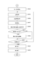
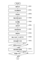
- step S ⁇ b> 201 the backlight control unit 160 turns on the light 45, and the reference data registration unit 113 displays a reference data setting screen on the monitor 201 of the console 200.
- step S ⁇ b> 202 the reference data registration unit 113 searches the console 200 for an analysis region for searching the tip portion 30 a outside the liquid C ⁇ b> 1 in the image (in the present embodiment, this is referred to as “first analysis region”). It is acquired and registered in the reference data storage unit 152 as reference data.
- step S203 the reference data registration unit 113 acquires from the console 200 an analysis region (in the present embodiment, this is referred to as a “second analysis region”) for searching for the liquid level SF1 in the image. Are registered in the reference data storage unit 152 as reference data.
- step S204 the reference data registration unit 113 acquires from the console 200 an analysis region (in the present embodiment, this is referred to as a “third analysis region”) for searching for the boundary portion BD1 in the image.
- an analysis region in the present embodiment, this is referred to as a “third analysis region” for searching for the boundary portion BD1 in the image.
- the execution order of steps S202 to S204 can be changed as appropriate.
- the reference data registration unit 113 may sequentially execute acquisition of the second analysis region, acquisition of the third analysis region, and acquisition of the first analysis region.
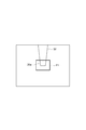
- FIG. 11 is a diagram illustrating an analysis area setting screen. This screen displays the image captured by the camera 43 and the analysis region input to the input device 202 by the user in an overlapping manner.
- An analysis area A1 in FIG. 11 indicates an area input for setting the first analysis area.
- the analysis region A1 is set so as to include the tip portion 30a outside the liquid C1.
- the analysis area A2 indicates an area input for setting the second analysis area.
- the analysis region A2 is set so as to include the liquid level SF1.
- the analysis area A3 indicates an area input for setting the third analysis area.
- the analysis region A3 is set so as to include the boundary portion BD1.
- the reference data registration unit 113 registers the analysis region A1 as the first analysis region in the reference data storage unit 152, registers the analysis region A2 as the second analysis region in the reference data storage unit 152, and sets the analysis region A3 as the first analysis region.
- the third analysis area is registered in the reference data storage unit 152.
- step S205 the reference data registration unit 113 acquires the image pattern of the tip portion 30a and registers it in the reference data storage unit 152 as reference data.
- FIG. 12 is a diagram illustrating an image pattern registration screen.
- This screen displays an image in the vicinity of the distal end portion 30a and a frame line P1 input to the input device 202 by the user in an overlapping manner.
- This screen may be an enlarged display of the analysis area A1 in FIG.
- a frame line P1 designates an area to be used as an image pattern.
- the reference data registration unit 113 registers the image of the area surrounded by the frame line P1 in the reference data storage unit 152 as an image pattern of the tip portion 30a.
- step S ⁇ b> 206 the reference data registration unit 113 outputs a command to insert the tip portion 30 a into the liquid C ⁇ b> 1 to the robot control unit 130.
- the robot control unit 130 controls the robot 10 to lower the dispenser 30 and insert the tip 30a into the liquid C1.
- Step S207 the reference data registration unit 113 acquires the image pattern of the tip portion 30a as in step S205, and registers this as reference data in the reference data storage unit 152. As described above, the reference data registration unit 113 registers the image pattern of the tip 30a outside the liquid C1 and the image pattern of the tip 30a in the liquid C1 as reference data. Thereafter, the backlight control unit 160 turns off the light 45.
- reference data registration unit 113 illustrated the case where the first analysis region, the second analysis region, the third analysis region, and the image pattern of the tip 30a inside and outside the liquid C1 are registered as reference data, It is not limited to this.
- the reference data registration unit 113 may register only a part of the reference data exemplified above.
- the reference data may be any data as long as it is necessary for the control of the robot 10. Therefore, the reference data registration unit 113 may register reference data different from those exemplified above. Good.
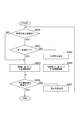
- FIG. 13 shows a control procedure when the liquid C1 in the container 90 is transferred to another container 90 as an example of the dispensing operation.
- the controller 100 first executes step S301.
- step S ⁇ b> 301 the container arrangement control unit 131 controls the arm 13 ⁇ / b> B so that the container 90 is arranged on the container holding unit 44.
- the container arrangement control unit 131 controls the arm 13B so as to remove the cap.
- step S302 the robot control unit 130 controls the arm 13A so as to place the distal end portion 30a of the dispenser 30 at a position for image acquisition.
- the position for image acquisition means a position that falls within the field of view of the camera 43 above the liquid level SF1.
- the backlight control unit 160 turns on the light 45, and the image processing unit 120 acquires an image from the camera 43.
- This image includes at least the tip 30a, a part of the liquid level SF1, and a part of the non-dispensing object C2.
- step S303 the image processing unit 120 acquires the position information of the liquid surface SF1 and the position information of the tip 30a based on the image acquired in step S302.
- the image processing unit 120 acquires information on the second analysis region from the reference data storage unit 152, and acquires position information on the liquid level SF1 from within the second analysis region.
- the image processing unit 120 detects a linear portion passing through the second analysis region, and acquires the position as position information of the liquid surface SF1.
- the image processing unit 120 acquires the first analysis region information and the image pattern of the tip 30a outside the liquid C1 from the reference data storage unit 152, and based on the image pattern, the position information of the tip 30a is first. Obtain from within the analysis area.
- the image processing unit 120 acquires the position of a portion that matches the image pattern of the tip portion 30a as position information of the tip portion 30a in the first analysis region.
- the image processing unit 120 may further acquire position information of the boundary part BD1.
- the image processing unit 120 acquires information on the third analysis region from the reference data storage unit 152, and acquires position information on the boundary portion BD1 from within the third analysis region.
- the image processing unit 120 detects a linear portion passing through the third analysis region, and acquires the position as position information of the boundary portion BD1.
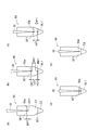
- step S304 the dispenser arrangement control unit 132 controls the arm 13A so that the distal end 30a is arranged at the suction start position OP1 (see FIG. 16A). Specifically, the dispenser arrangement control unit 132 moves based on the position information of the tip part 30a and the position information of the liquid level SF1 acquired in step S303 to move the tip part 30a at the start position OP1. Is calculated, and the arm 13A is controlled to move the tip 30a by the amount of movement.
- the start position OP1 is set in advance to a position at a predetermined depth (hereinafter referred to as “reference depth”) DP1 from the liquid level SF1.
- the reference depth DP1 is set in advance so as to satisfy the following conditions, for example.
- Condition 1-1) The depth is small compared to the depth from the liquid level SF1 to the boundary portion BD1.
- Condition 1-2) The tip 30a can be maintained in the liquid C1 even if a position control error occurs.
- step S305 the dispenser control unit 140 and the descent control unit 133 control the dispenser 30 and the robot 10 so as to perform the suction of the liquid C1.
- the dispenser control unit 140 controls the dispenser 30 so as to suck the liquid C1 from the container 90.
- the descent controller 133 sucks the liquid into the dispenser 30
- the dispenser 30 is based on the position information on the tip 30a, the position information on the liquid surface SF1, and the position information on the boundary BD1.
- the robot 10 is controlled to move down.
- the backlight control unit 160 turns off the light 45.
- step S ⁇ b> 306 the dispenser arrangement control unit 132 controls the arm 13 ⁇ / b> A so that the distal end portion 30 a is pulled out from the container 90.
- step S ⁇ b> 307 the container arrangement control unit 131 controls the arm 13 ⁇ / b> B so that the container 90 of the container holding unit 44 is replaced with another container 90.
- step S308 the dispenser arrangement control unit 132 controls the arm 13A so as to arrange the tip part 30a at the discharge start position.
- the discharge start position is set in advance to a position in the container 90.
- step S309 the dispenser control unit 140 controls the dispenser 30 so that the liquid C1 is discharged into the container 90.
- step S ⁇ b> 310 the dispenser arrangement control unit 132 controls the arm 13 ⁇ / b> A so that the distal end portion 30 a is pulled out from the container 90. This completes the dispensing operation.
- step S401 the dispenser control unit 140 controls the dispenser 30 so as to start suction of the liquid C1 in the container 90.
- step S ⁇ b> 402 the image processing unit 120 acquires an image from the camera 43.
- This image includes at least the tip 30a, a part of the liquid level SF1, and a part of the non-dispensing object C2.
- step S403 the image processing unit 120 acquires the position information of the liquid surface SF1, the position information of the boundary portion BD1, and the position information of the tip portion 30a based on the image acquired in step S402.
- the image processing unit 120 acquires information on the second analysis region from the reference data storage unit 152, and acquires position information on the liquid level SF1 from within the second analysis region.
- the image processing unit 120 detects a linear portion passing through the second analysis region, and acquires the position as position information of the liquid surface SF1.
- the image processing unit 120 acquires information on the third analysis region from the reference data storage unit 152, and acquires position information on the boundary portion BD1 from within the third analysis region.
- the image processing unit 120 detects a linear portion passing through the third analysis region, and acquires the position as position information of the boundary portion BD1.
- the image processing unit 120 acquires the image pattern of the tip 30a in the liquid C1 from the reference data storage unit 152, and based on the image pattern of the tip 30a, the position information of the tip 30a from the second analysis region. get.
- the image processing unit 120 acquires the position of a portion that matches the image pattern of the tip portion 30a as position information of the tip portion 30a in the second analysis region.
- step S404 the inclination detection unit 137 detects the inclination of the boundary part BD1 based on the image acquired in step S402.
- the inclination detection unit 137 may detect the inclination of the boundary part BD1 based on the position information of the boundary part BD1 acquired by the image processing unit 120.
- the target position setting unit 136 uses the center position of the container 90 (for example, the central axis CL1 of the side wall 91) as a reference.
- the position shifted in the direction of decreasing the inclination of BD1 is set as the final target position GL1 (see FIG. 17B).
- the target position setting unit 136 sets the final target position GL1 so that the horizontal distance between the final target position GL1 and the central axis CL1 of the container 90 becomes a predetermined horizontal offset value HO1.
- the horizontal offset value HO1 is set in advance so as to satisfy the following condition, for example.
- the dispenser 30 does not interfere with the side wall 91 of the container 90. Also in this case, the target position setting unit 136 sets the final target position GL1 so that the distance between the final target position GL1 and the boundary portion BD1 in the vertical direction becomes the predetermined vertical offset value VO2.
- the vertical offset value VO2 is also set in advance so as to satisfy the same condition as the vertical offset value VO1.
- step S406 the image processing unit 120 acquires an image from the camera 43 as in step S402.
- step S407 the image processing unit 120 acquires the position information of the liquid surface SF1, the position information of the boundary part BD1, and the position information of the tip part 30a, as in step S403.
- step S408 the inclination detection unit 137 detects the inclination of the boundary part BD1 as in step S404.
- the first mode control unit 133a controls the robot 10 so as to lower the tip portion 30a following the lowering of the liquid level SF1 by lowering the dispenser 30 by the arm 13A (hereinafter, referred to as “the first mode control unit 133a”). This control is referred to as “first mode lowering control”).
- the first mode control unit 133a performs the first mode lowering control based on the position information of the liquid level SF1 and the position information of the tip part 30a. Specifically, the first mode control unit 133a executes the first mode lowering control so that the depth from the liquid level SF1 to the tip 30a is maintained at a value close to the reference depth DP1 (FIG. 16 ( b)).
- the reference distance setting unit 134 sets the reference distance RF1 (see FIG. 16B).
- the reference distance setting unit 134 may be configured to increase the reference distance RF1 as the moving speed of the distal end portion 30a increases.
- the reference distance setting unit 134 may be configured to set the reference distance RF1 to a value proportional to the descending speed of the distal end portion 30a.
- the descending speed of the tip portion 30a can be calculated based on, for example, the difference between the position information of the tip portion 30a acquired this time and the position information of the tip portion 30a acquired last time. It is also possible to calculate the descending speed based on the average value of the differences calculated over a plurality of times.
- step S411 the boundary monitoring unit 135 determines whether or not the boundary part BD1 has changed based on the position information of the boundary part BD1 acquired in step S407. If no change is detected at the boundary in step S411, the controller 100 advances the process to step S413.
- step S412 the target position setting unit 136 sets the final target position GL1 in the same manner as in step S405, based on the position information of the boundary part BD1 acquired in step S407. That is, the target position setting unit 136 updates the final target position GL1 based on the position information of the boundary part BD1 when the robot 10 moves the dispenser 30 downward. Further, the target position setting unit 136 updates the final target position GL1 when the boundary monitoring unit 135 detects a change in the boundary part BD1.
- step S413 the switching unit 133c determines whether the distance from the tip 30a to the final target position GL1 (hereinafter referred to as “first remaining distance”) LD1 is smaller than the reference distance RF1 set in advance in step S410. Determine whether or not.
- first remaining distance the distance from the tip 30a to the final target position GL1 (hereinafter referred to as “first remaining distance”) LD1 is smaller than the reference distance RF1 set in advance in step S410. Determine whether or not.
- the controller 100 returns the process to step S406. Thereby, the control by the first mode control unit 133a is continued.
- step S414 the switching unit 133c switches the control by the first mode control unit 133a to the control by the second mode control unit 133b.
- step S413 and S414 the switching unit 133c switches the control by the first mode control unit 133a to the control by the second mode control unit 133b in response to the leading end 30a approaching the final target position GL1. .
- step S415 the image processing unit 120 acquires an image from the camera 43 as in step S402.
- step S416 the image processing unit 120 acquires the position information of the liquid level SF1, the position information of the boundary part BD1, and the position information of the tip part 30a as in step S403.
- step S417 the inclination detection unit 137 further detects the inclination of the boundary part BD1 as in step S404.
- step S4108 the second mode control unit 133b controls the robot 10 so that the tip 30a is brought close to the final target position GL1 by lowering the dispenser 30 with the arm 13A (hereinafter, this control is referred to as “first control”). "Two-mode descent control").
- the second mode control unit 133b may perform control to suppress overshooting as compared to the first mode control unit 133a.
- the first mode control unit 133a may perform control to increase responsiveness compared to the second mode control unit 133b.
- feedforward control that compensates for delay in image processing is performed, and in the control by the second mode control unit 133b, the feedforward control is not performed. Is mentioned.
- the control by the first mode control unit 133a there is a configuration in which the gain for the deviation is set higher than the control by the second mode control unit 133b.
- Step S419 the controller 100 executes Step S419 similar to Step S411.
- the boundary monitoring unit 135 determines whether there is a change in the boundary part BD1 based on the position information of the boundary part BD1 acquired in step S416. If no change is detected in the boundary portion BD1 in step S419, the controller 100 advances the process to step S421.
- Step S419 when a change is detected in the boundary portion BD1, the controller 100 executes Step S420 similar to Step S412.
- the target position setting unit 136 updates the final target position GL1 based on the position information of the boundary part BD1 acquired in step S416.
- Step S421 the second mode control unit 133b detects whether or not the first remaining distance LD1 is equal to or less than zero. When it is determined that the first remaining distance LD1 is greater than zero (see FIG. 16C), the controller 100 returns the process to step S415. Thereby, the control by the second mode control unit 133b is continued.
- Step S422 the controller 100 executes Step S422.
- the second mode control unit 133b controls the robot 10 to stop the lowering of the dispenser 30.
- the descent control of the dispenser 30 by the descent control unit 133 is completed.
- the lowering control unit 133 controls the robot 10 to lower the tip 30a to the final target position GL1 by lowering the tip 30a following the lowering of the liquid level SF1. To do.
- step S423 the dispenser control unit 140 controls the dispenser 30 so as to stop the suction of the liquid C1 (see FIG. 16 (e)). Thereafter, the backlight control unit 160 turns off the light 45. This completes the suction procedure.
- step S305 may be executed in a state where the container 90 is inclined in a direction in which the inclination of the boundary portion BD1 with respect to the liquid surface SF1 is gentle.
- the lowering control unit 133 controls the robot 10 so as to lower the distal end portion 30a of the dispenser 30 in an oblique direction corresponding to the inclination of the container 90 (FIGS. 19A to 19). d)).
- Lowering the distal end portion 30a in an oblique direction corresponding to the inclination of the container 90 means lowering the distal end portion 30a so as not to contact the side wall 91 of the container 90.
- the lowering control unit 133 may control the robot 10 to lower the distal end portion 30a along the inclined central axis CL1 of the container 90.
- the controller 100 sets, as the final target position GL1, a position shifted in the direction in which the inclination of the boundary portion BD1 is lowered with respect to the central axis CL1 of the container 90, and the inclination of the boundary portion BD1 with respect to the liquid surface SF1 is moderated. It may be configured to perform only one of making the container 90 tilted in the direction to be performed, or may be configured to perform both of these in combination.
- the timing and method for setting the container 90 in a state in which the inclination of the boundary BD1 with respect to the liquid level SF1 is gentle For example, after the container placement control unit 131 controls the robot 10 to place the container 90 on the container holding unit 44, the tilt control unit 138 controls the robot 10 so that the container 90 is tilted by tilting the rack 40. Also good.
- the container placement control unit 131 may control the robot 10 so as to place the container 90 on the container holding unit 44.
- the container 90 may be disposed so as to be inclined in a direction in which the inclination of the boundary portion BD1 with respect to the liquid surface SF1 becomes gentle before being transferred from outside the field of view of the camera 43 into the field of view.
- the container placement control unit 131 controls the robot 10 so that the container 90 is transported from outside the field of view of the camera 43 and placed on the container holding unit 44 while maintaining the tilt of the container 90. Good.
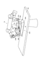
- the controller 100 uses the stopper 61 to keep the inclination of the rack 40 constant.
- the robot 10 may be controlled so as to maintain the above. For example, the controller 100 raises the upper portion 46a of the handle 46 by the arm 13B and tilts the stage 41, so that the arm 61A tilts the stopper 61 toward the hinge 52 so that the edge of the stage 41 is fitted in the groove 61b.
- the robot 10 may be controlled (see FIG. 20).
- the edge of the stage 41 is fitted into the groove 61b, the inclination of the rack 40 is maintained by the stopper 61, so that the handle 46 and the stopper 61 can be released from the arms 13A and 13B.
- the arm 13A it is possible to cause the arm 13A to perform the operation of arranging the dispenser 30 at the position for image acquisition.
- the dispenser 30 is a manual type, the dispenser 30 can be operated by cooperation of the arms 13A and 13B.
- the stopper 61 the arms 13A and 13B can be used for a wider range of work.
- the controller 100 may execute in the middle of step S305 that the container 90 is tilted in a direction in which the boundary of the boundary portion BD1 with respect to the liquid level SF1 becomes gentle.
- the tilt control unit 138 may control the robot 10 so that the container 90 is tilted by tilting the rack 40 while the robot 10 is lowering the tip portion 30a (hereinafter referred to as “tilt control”). Called).
- the tilt control unit 138 may control the robot 10 so that the container 90 is tilted in accordance with the distal end portion 30a approaching the final target position GL1.
- FIG. 18 is a flowchart illustrating the tilt control procedure.
- the controller 100 first executes step S501.
- step S501 the tilt control unit 138 determines the distance from the liquid level SF1 to the boundary part BD1 (hereinafter referred to as “second remaining distance”) based on the position information acquired in any of steps S403, S406, and S414. .) Wait until LD2 becomes smaller than the reference distance RF3 (see FIGS. 21A and 21B).
- the reference distance RF3 is set in advance such that the tilt of the container 90 and the dispenser 30 is started before the liquid level SF1 reaches the boundary BD1.
- step S502 the controller 100 executes steps S502 to S506.
- the inclination detection unit 137 detects the inclination angle ⁇ of the boundary part BD1 with respect to the liquid level SF1 based on the image acquired in any of steps S402, S405, and S413 (see FIG. 21C).
- the inclination angle ⁇ can be calculated, for example, by complementing the shape of the boundary portion BD1 with the wire diameter.
- step S503 the tilt control unit 138 sets a target tilt angle RF5 corresponding to the tilt angle ⁇ .
- the tilt control unit 138 sets the target tilt angle RF5 to a value equal to the tilt angle ⁇ .
- step S504 the tilt control unit 138 controls the robot 10 to start tilting the container 90 and the dispenser 30 (see FIGS. 21D and 21E).
- the tilt control unit 138 controls the robot 10 to tilt the container 90 by tilting the rack 40 by raising the upper portion 46a of the handle 46 by the arm 13B (see FIG. 22).
- the rack 40 tilts around an axis along the direction in which the camera 43, the container 90, and the light 45 are arranged.
- the tilt control unit 138 controls the robot 10 so that the dispenser 30 is tilted by the arm 13A in accordance with the tilt of the container 90.
- step S505 the tilt control unit 138 waits for the tilt angle of the container 90 and the dispenser 30 to be equal to or greater than the target tilt angle RF5.
- step S506 the tilt control unit 138 controls the robot 10 so as to stop the tilt of the container 90 and the dispenser 30.
- the tilt angle ⁇ is determined substantially uniformly depending on the characteristics of the centrifuge and may be handled as a constant. In such a case, step S502 for detecting the tilt angle ⁇ may be omitted.
- the image processing unit 120 extracts a linear pattern from the image as a search target with a linear pattern whose inclination is defined in advance, and based on the extraction result, the liquid pattern SF1 Surface position information may be acquired.
- the image processing unit 120 may define the inclination of the linear pattern to be searched according to the inclination of the container 90.
- FIG. 23 shows an image captured by the camera 43 in the configuration including the rack 40.
- the image processing unit 120 searches the linear pattern LP1 that is inclined at the same angle in the opposite direction to the direction D1 in which the container 90 and the camera 43 are inclined, as a search target.
- the position information of the liquid level SF1 may be acquired based on the extraction result.
- the image processing unit 120 may set the inclination angle of the linear pattern LP1 to one value, or may set an upper limit value and a lower limit value so that the inclination angle of the linear pattern LP1 has a width.
- the image processing unit 120 may define the inclination of the linear pattern to be searched according to the thickness of the container 90 (the inner diameter of the side wall 91). For example, the image processing unit 120 may define the inclination of the linear pattern to be searched as the container 90 becomes thinner (the inner diameter of the side wall 91 becomes smaller).
- the peripheral portion of the liquid surface SF1 rises as it approaches the inner surface of the side wall 91 due to the surface tension of the liquid C1 (hereinafter, the raised portion is referred to as a “raised portion”).
- the raised portion is referred to as a “raised portion”.
- FIG. 23B when the container 90 becomes thinner, the ratio of the rising portion on the liquid level SF1 increases. In such a case, if the inclination of the linear pattern to be searched is set large, only the rising portion may be extracted. If only the rising portion is extracted, the position information of the liquid level SF1 is acquired on the assumption that the entire liquid level is inclined in the same manner as the rising portion, so that the accuracy of the position information of the liquid level SF1 is reduced (see FIG. (See the linear pattern LP1 in the middle).
- the liquid surface SF1 in the vicinity of the center of the side wall 91 having a small rise is extracted by using the linear pattern LP2 having a smaller inclination (eg, horizontal) as compared with the linear pattern LP1 as a search target. Is possible. Thereby, the precision fall of the positional information on liquid level SF1 can be suppressed. 1.4 Effects of the first embodiment
- the dispensing system 1 includes the robot 10 that moves the dispenser 30 for sucking the liquid C1 to be dispensed, the tip 30a of the dispenser 30, and the liquid C1.
- the camera 43 for capturing an image including the liquid level SF1 and the non-dispensing object C2 positioned below the liquid level SF1, the position information of the liquid level SF1, and the liquid C1 based on the image.
- the image processing unit 120 that acquires the position information of the boundary portion BD1 between the non-dispensing object C2 and the position information of the tip portion 30a of the dispenser 30 and the liquid C1 are sucked into the dispenser 30.
- a lowering control unit 133 that controls the robot 10 to lower the dispenser 30; Is provided.
- this dispensing system 1 it is possible to keep the tip 30a at a shallow position from the liquid surface SF1 by lowering the tip 30a based on the positional relationship between the liquid level SF1 and the tip 30a. Thereby, the liquid adhering to the outer periphery of the front-end
- tip part 30a is reduced.
- the tip portion 30a By lowering the tip portion 30a based on the positional relationship between the boundary portion BD1 and the tip portion 30a, the tip portion 30a can be brought closer to the boundary portion BD1. Thereby, the liquid C1 is sufficiently sucked.
- the tip portion 30a can be maintained in the liquid, and the occurrence of idle suction (gas suction) can be suppressed. Therefore, more reliable dispensing work can be executed.
- the position information of the tip 30a, the position information of the liquid surface SF1, and the position information of the boundary part BD1 are acquired for each dispensing operation based on the image information. Since the position information of the liquid surface SF1 and the position information of the boundary portion BD1 are likely to vary, a more reliable dispensing operation can be executed by acquiring these pieces of information for each dispensing operation.
- the chip 32 is detachable from the main body 31, the position of the tip 30 a relative to the main body 31 is likely to vary. For this reason, the effect of acquiring the positional information on the tip portion 30a, the positional information on the liquid level SF1, and the positional information on the boundary portion BD1 for each dispensing operation becomes more remarkable.
- the dispensing system 1 may further include a target position setting unit 136 that sets the final target position GL1 based on the position information of the boundary BD1, and the lowering control unit 133 follows the lowering of the liquid level SF1.
- the robot 10 may be controlled such that the tip 30a of the dispenser 30 is lowered and the tip 30a of the dispenser 30 is lowered to the final target position GL1.
- the tip part 30a can be more reliably maintained at a shallow position from the liquid level SF1.
- the tip part 30a can be brought closer to the boundary part BD1 more reliably. Therefore, more reliable dispensing work can be executed.
- the dispensing system 1 only needs to lower the dispenser 30 based on the position information of the tip portion 30a, the position information of the liquid level SF1, and the position information of the boundary portion BD1, so that the target It is not essential to further include the position setting unit 136, to lower the tip part 30a following the lowering of the liquid level SF1, and to lower the tip part 30a to the final target position GL1.
- the target position setting unit 136 may update the final target position GL1 based on the position information of the boundary part BD1 when the robot 10 lowers the dispenser 30. In this case, since the final target position GL1 can be updated according to the movement of the boundary portion BD1 even when the position of the boundary portion BD1 varies, the tip portion 30a can be brought closer to the boundary portion BD1 more reliably. It becomes possible. Therefore, more reliable dispensing work can be executed. However, it is not essential to update the final target position GL1 by the target position setting unit 136.
- the dispensing system 1 may further include a boundary monitoring unit 135 that detects a change in the boundary part BD1 based on the image, and the target position setting unit 136 detects a change in the boundary part BD1 by the boundary monitoring unit 135.
- the final target position GL1 may be updated based on the position information of the boundary portion BD1.
- the calculation load can be reduced by updating the final target position GL1 only when a change is detected in the boundary portion BD1.
- the target position setting unit 136 may be configured to update the final target position GL1 every time the position information of the boundary part BD1 is acquired.
- the lowering control unit 133 includes a first mode control unit 133a that controls the robot 10 to lower the tip part 30a of the dispenser 30 following the lowering of the liquid level SF1, and a tip part 30a of the dispenser 30.
- the second mode control unit 133b that controls the robot 10 to move down to the final target position GL1, and the control by the first mode control unit 133a as the tip 30a of the dispenser 30 approaches the final target position GL1.
- a switching unit 133c that switches to control by the second mode control unit 133b.
- priority is given to following the liquid level SF1, so that the tip 30a can be more reliably kept at a shallow position from the liquid level SF1.
- the first mode control unit 133a performs control to increase responsiveness compared to the second mode control unit 133b
- the second mode control unit 133b performs control to suppress overshoot compared to the first mode control unit 133a. May be.
- the delay of the tip 30a with respect to the lowering of the liquid level SF1 is reduced, so that the position of the tip 30a can be kept at a shallower position from the liquid level SF1.
- the second mode control unit 133b the amount of overshoot with respect to the final target position GL1 is reduced, so that the tip 30a can be brought closer to the boundary BD1 more reliably. Therefore, more reliable dispensing work can be executed.
- the switching unit 133c may switch the control by the first mode control unit 133a to the control by the second mode control unit 133b as the remaining distance LD1 becomes smaller than the preset reference distance RF1. In this case, switching from the first mode control unit 133a to the second mode control unit 133b can be more reliably performed by simplifying the determination criterion.
- the criterion for switching is not limited to this.
- the dispensing system 1 may further include a reference distance setting unit 134 that increases the reference distance RF1 as the moving speed of the tip 30a of the dispenser 30 increases.
- a reference distance setting unit 134 that increases the reference distance RF1 as the moving speed of the tip 30a of the dispenser 30 increases.
- the lowering control unit 133 is configured so that the tip of the dispenser 30 corresponds to the inclination of the container 90 in a state where the liquid C1 and the non-dispensing object C2 are accommodated in the inclined container 90 within the field of view of the camera 43.
- the robot 10 may be controlled so that 30a is lowered in an oblique direction. In this case, the suction of the liquid C1 can be performed in a state in which the container 90 is inclined so that the inclination of the boundary portion BD1 with respect to the liquid level SF1 is gentle as compared with the case where the container 90 is upright.
- the dispensing system 1 conveys the container 90 from outside the field of view of the camera 43 while maintaining the state where the container 90 is inclined in a direction that makes the inclination of the boundary portion BD1 with respect to the liquid level SF1 gentle. You may further provide the container arrangement
- a tilt control unit 138 for controlling the robot 10 so as to tilt the container 90 in a direction in which the tilt of the boundary BD1 with respect to the liquid level SF1 may be further provided.
- the container 90 can be tilted according to the state of the boundary portion BD1.
- the dispensing system 1 further includes an inclination detection unit 137 that detects the inclination of the boundary part BD1 with respect to the liquid surface SF1 based on the image, and the tilt control unit 138 detects the inclination of the boundary part BD1 by the inclination detection unit 137.
- the robot 90 tilts the container 90 and the dispenser 30 in a direction in which the inclination of the boundary portion BD1 becomes gentle as the tip 30a of the dispenser 30 approaches the final target position GL1. 10 may be controlled.
- the container 90 is tilted after the liquid C1 in the container 90 is reduced by suction, the leakage of the liquid C1 due to the tilting of the container 90 can be prevented more reliably.
- the tilt control unit 138 may control the robot 10 to tilt the container 90 and the dispenser 30 before the liquid level SF1 reaches the boundary BD1. In this case, the fluctuation of the boundary portion BD1 is more reliably suppressed. Thereby, since the position of the final target position GL1 is further stabilized, the tip portion 30a can be brought closer to the boundary portion BD1 more reliably.
- the dispensing system 1 may include a double-armed robot 10 having first and second arms 13A and 13B.
- the lowering control unit 133 controls the robot 10 so as to lower the dispenser 30 by the first arm 13A, and the tilt control unit 138 tilts the dispenser 30 by the first arm 13A, and the second arm
- the robot 10 may be controlled so that the container 90 is tilted by 13B.
- the two-arm robot 10 can be effectively used, and the suction procedure involving the tilting of the container 90 and the dispenser 30 can be made efficient.
- the robot 10 is of the double arm type.
- the dispensing system 1 may include a device that tilts the container 90 separately from the robot 10.
- the tilt detector 137 may detect the tilt angle ⁇ of the boundary BD1 with respect to the liquid level SF1 based on the image.
- the tilt control unit 138 may control the robot 10 to tilt the container 90 and the dispenser 30 at the target tilt angle RF5 corresponding to the tilt angle ⁇ .
- the fluctuation of the boundary portion BD1 is more reliably suppressed.
- the tip 30a can be brought closer to the boundary BD1 more reliably. Therefore, more reliable dispensing work can be executed.
- the target position setting unit 136 sets the position shifted in the direction of decreasing the inclination of the boundary BD1 with respect to the center position of the container 90 as the final target. You may set as position GL1. In this case, the tip portion 30a can be advanced to a deeper position in the container 90, and more liquid C1 can be sucked (see FIGS. 17B to 17E). Therefore, more reliable dispensing work can be executed. However, it is not indispensable to set the position shifted in the direction in which the boundary portion BD1 is inclined downward with respect to the center position as the final target position GL1.
- the dispensing system 1 may further include a rack 40 that holds both the camera 43 and the container 90.
- the lowering control unit 133 may control the robot 10 so as to lower the distal end portion 30a of the dispenser 30 in an oblique direction in a state where the inclination of the container 90 is maintained by the rack 40.
- the container 90 is more reliably maintained within the field of view of the camera 43 even when the container 90 is tilted.
- the distance between the camera 43 and the container 90 is stabilized, blurring of the image is suppressed. Therefore, since the acquisition of various position information based on the image can be more reliably executed, a more reliable dispensing operation can be executed. However, it is not essential to provide the rack 40.
- the dispensing system 1 may further include a rack 40 that holds both the camera 43 and the container 90.
- the tilt control unit 138 may control the robot 10 to tilt the container 90 by tilting the rack 40.
- the container 90 is more reliably kept within the field of view of the camera 43.
- the distance between the camera 43 and the container 90 is stabilized, blurring of the image is suppressed. Therefore, since the acquisition of various position information based on the image can be more reliably executed, a more reliable dispensing operation can be executed. However, it is not essential to provide the rack 40.
- the dispensing system 1 may further include a light 45 that irradiates the container 90 with light.
- the light 45 may be held on the rack 40 together with the camera 43 and the container 90 in an arrangement in which the container 90 is sandwiched between the light 45 and the camera 43. In this case, since the light 45 also tilts together with the container 90, it is possible to more reliably execute acquisition of various position information based on the image. Therefore, more reliable dispensing work can be executed. However, it is not essential to provide the light 45.
- the light 45 may be irradiated with red visible light. In this case, the detection sensitivity of the liquid level SF1 and the boundary portion BD1 in image processing can be increased.
- a backlight control unit 160 that turns off the light 45 in at least a part of the time period when the camera 43 is not capturing an image may be further provided. In this case, the lighting time of the light 45 can be reduced and the burden on the operator's eyes can be reduced.
- the image processing unit 120 may extract a linear pattern from the image with a linear pattern with a predetermined inclination defined as a search target, and obtain position information of the liquid level SF1 based on the extraction result. There is a lot of noise information such as water droplets around the liquid surface SF1. By defining the linear pattern to be searched for in advance, the noise information can be removed and the position information of the liquid level SF1 can be obtained with high accuracy.
- the image processing unit 120 may define the inclination of the linear pattern to be searched according to the inclination of the container 90.
- the inclination of the liquid level SF1 correlates with the inclination of the container 90. For this reason, the position information of the liquid level SF1 can be acquired with higher accuracy by defining the inclination of the linear pattern to be searched according to the inclination of the container 90.
- the image processing unit 120 may define the inclination of the linear pattern to be searched according to the thickness of the container 90.
- the inclination of the linear pattern suitable for acquiring the position information of the liquid level SF1 tends to change depending on the thickness of the container 90. For example, when the container 90 becomes thin, the ratio of the above-mentioned rising portion on the liquid surface SF1 (the portion rising on the peripheral edge portion of the liquid surface SF1 due to the surface tension of the liquid C1) increases. In such a case, if the inclination of the linear pattern is set large, only the rising portion is extracted, and the accuracy of the position information of the liquid surface SF1 may be lowered. Therefore, by defining the inclination of the linear pattern according to the thickness of the container, the position information of the liquid level can be acquired with higher accuracy.
- the dispensing system 1 includes a console 200 for registering reference data for dispensing work performed by the robot 10, and the tip 30a of the dispenser 30 within the field of view of the camera 43 when the reference data is not registered.
- An interrupt unit 112 for stopping the robot 10 after entering and restarting the operation of the robot 10 after registration of the reference data, and a screen for setting reference data when the interrupt unit 112 stops the robot 10 May be further included on the console 200, and a reference data registration unit 113 that acquires and registers reference data from the console 200.
- the operation of the robot 10 is temporarily interrupted by the interrupt unit 112, and the reference data registration unit 113.
- the dispensing system 1 may further include a process setting unit 111 that sets a work process of the robot 10 including a plurality of types of dispensing work.
- the interrupt unit 112 executes stopping the robot 10 when the reference data is not registered for each dispensing operation, and the reference data registering unit 113 is configured so that the interrupt unit 112 stops the robot 10 every time. Next, reference data corresponding to the dispensing operation scheduled to be executed may be acquired and registered. In this case, even when an operation program including a plurality of types of dispensing operations is constructed, reference data for each dispensing operation can be appropriately set during the operation of the robot 10.
- the reference data registration unit 113 registers the image pattern of the tip 30a of the dispenser 30 as reference data, and the image processing unit 120 uses the image pattern of the tip 30a of the dispenser 30 based on the image pattern. You may acquire the positional information on the front-end
- the reference data registration unit 113 searches for the first analysis region for searching the tip 30a of the dispenser 30 outside the liquid C1 in the image and the liquid level SF1 in the image as reference data.
- the second analysis region and the third analysis region for searching the boundary portion BD1 in the image may be further registered.
- the image processing unit 120 acquires the position information of the tip 30a of the dispenser 30 from the first or second analysis region, acquires the position information of the liquid level SF1 from the second analysis region,
- the position information of the boundary portion BD1 may be acquired from within the analysis region. In this case, by limiting the search area for position information, it is possible to further increase the processing speed and position information.
- the rack 40 includes a container holding unit 44 that is fixed to the stage 41 and holds the container 90, and a camera 43 that is fixed to the stage 41 at a position where the container 90 can be imaged.
- the container 90 and the camera 43 can be tilted together by tilting the stage 41. For this reason, even in the dispensing operation involving the operation of tilting the container 90, the arrangement of the container 90 in the field of view can be kept constant. In addition, since the distance between the container 90 and the camera 43 is stable, blurring of the image is suppressed. By these actions, when information necessary for dispensing is acquired by image processing, the reliability of the acquisition result is improved. Therefore, the information obtained by processing the image obtained using the rack 40 is used for the control of a device for dispensing work (for example, the robot 10 and the dispenser 30), thereby ensuring more reliable dispensing.
- a dispensing system capable of performing work can be constructed.
- the rack 40 may further include a stage holding unit 50 that holds the stage 41 so as to be rotatable around a first axis along the direction in which the container holding unit 44 and the camera 43 are arranged.
- a stage holding unit 50 that holds the stage 41 so as to be rotatable around a first axis along the direction in which the container holding unit 44 and the camera 43 are arranged.
- an image including the container 90 that is tilted around the first axis is captured with a line of sight along the first axis.
- the image of the liquid level SF1 is generally maintained in a single line shape, so that the image recognition of the liquid level SF1 is easy. Therefore, since the reliability of the information acquisition result by image processing is further improved, a dispensing system capable of performing more reliable dispensing work can be constructed.
- the rack 40 may further include a light 45 fixed to the stage 41 at a position where the container 90 can be irradiated with light.
- the light 45 can be tilted together with the container 90 and the camera 43 by tilting the stage 41.
- the illumination state of the container 90 can be kept constant even in the dispensing work involving the work of tilting the container 90.
- the arrangement of the light 45 with respect to the container 90 and the camera 43 is stabilized, the brightness distribution in the image is stabilized. By these actions, the reliability of the information acquisition result by image processing is further improved. Therefore, it is possible to construct a dispensing system that can execute more reliable dispensing work.
- the container holding unit 44 may be located between the camera 43 and the light 45. In this case, since the influence of the reflected light on the outer surface of the container 90 is suppressed, the reliability of the information acquisition result by image processing is further enhanced. Therefore, it is possible to construct a dispensing system that can execute more reliable dispensing work.
- the dispensing system in which the rack 40 is useful is not necessarily limited to the dispensing system 1 described above.
- At least a rack 40, a robot, and a controller are provided.
- the controller controls the robot 10 to transport the container 90 and hold it in the container holding unit 44, and based on the image captured by the camera 43.
- the robot 10 is controlled to tilt the rack 40, and the liquid C1 is sucked into the dispenser 30, the separation is performed based on the position information of the liquid surface SF1.
- the dispensing system is configured to execute the control of the robot 10 so as to lower the pouring device 30, the rack 40 can be used effectively.
- the rack 40 can be used more effectively by controlling the robot 10 so that the rack 40 is tilted around the first axis by the controller.
- the rack includes a container holding unit that holds a container that holds a liquid to be dispensed and is fixed to the stage, and a camera that is fixed to the stage at a position where the container can be imaged. Since what kind of thing may be sufficient, the specific structure is not restricted to what was illustrated as the rack 40 mentioned above. Hereinafter, modified examples of the rack will be described with reference to FIGS.
- a rack 40A shown in FIGS. 24 to 27 is obtained by replacing the container holding unit 44, the stage holding unit 50, and the angle holding mechanism 60 of the rack 40 with a container holding unit 44A, a stage holding unit 50A, and an angle holding mechanism 60A, respectively. is there.
- the container holding unit 44A includes a first holder 70A, a second holder 70B, and elastic members 78A and 78B.
- “up and down” in the description of the first holder 70A, the second holder 70B, and the elastic members 78A and 78B means up and down when the upper surface of the stage 41 is horizontal.
- the first holder 70A and the second holder 70B are positioned so as to sandwich the central axis CL2 of the camera 43, and are configured to sandwich the container 90 in proximity to each other.
- two guides 71A and 71B are provided on the upper surface of the stage 41, the first holder 70A is attached to the guide 71A, and the second holder 70B is attached to the guide 71B.
- the guides 71A and 71B are arranged in a direction along the central axis CL2, and extend in a direction orthogonal to the central axis CL2. As viewed from vertically above, the guide 71A is located on one side of the central axis CL2, and the guide 71B is located on the other side of the central axis CL2.
- the first holder 70A has a slide block 72A, a slide plate 73A, a columnar portion 74A, and a contact portion 75A.
- the slide block 72A is provided on the guide 71A and is movable along the guide 71A.
- the slide block 72A is attached to the guide 71A via a plurality of balls, for example.
- the slide plate 73A is provided on the slide block 72A and protrudes toward the guide 71B in the direction along the central axis CL2.
- the columnar portion 74A protrudes from the upper surface of the slide plate 73A.
- the columnar portion 74A protrudes to a position higher than the central axis CL2.
- the columnar portion 74A is located on a portion of the slide plate 73A that protrudes toward the guide 71B.
- the contact portion 75A of contact parts are provided in the upper part of 74 A of columnar parts.
- the contact portion 75A protrudes toward the central axis CL2 at the upper portion of the columnar portion 74A.
- a groove 75a along the vertical direction is formed on the surface on the central axis CL2 side.
- the second holder 70B has a slide block 72B, a slide plate 73B, a columnar portion 74B, and a groove 75b.
- the slide block 72B is provided on the guide 71B and is movable along the guide 71B.
- the slide block 72B is attached to the guide 71B via a plurality of balls, for example.
- the slide plate 73B is provided on the slide block 72B and protrudes toward the guide 71A in the direction along the central axis CL2.
- the columnar portion 74B protrudes from the upper surface of the slide plate 73B.
- the columnar portion 74B protrudes to a position higher than the central axis CL2.
- the columnar portion 74B is located on a portion of the slide plate 73B that protrudes toward the guide 71A, and faces the columnar portion 74A across the central axis CL2.
- the contact part 75B is provided in the upper part of the columnar part 74B.
- the contact part 75B protrudes toward the central axis CL2 at the upper part of the columnar part 74B.
- a groove 75b along the vertical direction is formed on the surface on the central axis CL2 side.
- the first holder 70A can approach or separate from the one side with respect to the central axis CL2, and the second holder 70B can approach or separate from the opposite side of the first holder 70A with respect to the central axis CL2.
- the contact portions 75A and 75B approach or separate from each other. Thereby, it is possible to sandwich the container 90 between the contact portions 75A and 75B.
- the side wall 91 of the container 90 sandwiched between the contact portions 75A and 75B is along the grooves 75a and 75b. Thereby, the side wall 91 becomes perpendicular to the upper surface of the stage 41.
- the contact portions 75A and 75B may be formed integrally with the columnar portions 74A and 74B, or may be formed as separate bodies and fixed to the columnar portions 74A and 74B, respectively. From the viewpoint of more reliably preventing damage to the container 90, the contact portions 75A and 75B may be made of a softer material than the columnar portions 74A and 74B. For example, when the columnar portions 74A and 74B are made of a metal material, the contact portions 75A and 75B may be made of a resin material.
- the container 90 can be accurately held within the field of view of the camera 43 by a simple procedure. For example, in a state where the contact portions 75A and 75B are close to each other by the repulsive force of the elastic members 78A and 78B, the bottom portion 92 of the container 90 is inserted between the grooves 75a and 75b from above, and the container 90 is pushed down as it is.
- the container 90 can be held by the container holding part 44A only by arranging the side wall 91 between the contact parts 75A and 75B.
- the elastic members 78A and 78B generate a repulsive force so that the first holder 70A and the second holder 70B are close to each other.
- a protruding portion 76A that protrudes toward the stage 41 is formed at a portion that protrudes toward the guide 71B.
- a convex portion 77A is formed opposite the convex portion 76A from the opposite side of the second holder 70B in the direction orthogonal to the central axis CL2.
- the elastic member 78A is, for example, a coil spring, and is disposed between the convex portions 76A and 77A in a compressed state. Thereby, the repulsive force of the elastic member 78A acts on the second holder 70B side with respect to the first holder 70A.
- a convex portion 76B that protrudes toward the stage 41 is formed on a portion of the slide plate 73B of the second holder 70B that protrudes toward the guide 71A.
- a convex portion 77B is formed opposite the convex portion 76B from the opposite side of the first holder 70A in the direction orthogonal to the central axis CL2.
- the elastic member 78B is a coil spring, for example, and is disposed between the convex portions 76B and 77B in a compressed state. Thereby, the repulsive force of the elastic member 78B acts on the first holder 70A side with respect to the second holder 70B.
- Link mechanism The rack 40 ⁇ / b> A may further include a link mechanism 80.
- the link mechanism 80 interlocks the first holder 70A and the second holder 70B so that the movement amounts of the first holder 70A and the second holder 70B when approaching or separating from each other are equal.
- the link mechanism 80 includes pins 81A and 81B and a link 83.
- the above-described slide plates 73A and 73B also project toward the central axis CL2 side.
- the pin 81A protrudes from the upper surface of the portion of the slide plate 73A that protrudes toward the central axis CL2.
- the pin 81A is located closer to the guide 71A than the columnar portion 74A.
- the pin 81B protrudes from the upper surface of the portion of the slide plate 73B that protrudes toward the central axis CL2.
- the pin 81B is located closer to the guide 71B than the columnar portion 74B.
- the link 83 is mounted on the stage 41 so as to be rotatable around a vertical axis.
- the rotation center of the link 83 passes through a position equidistant from the pins 81A and 81B and intersects the center axis CL2.
- the link 83 is bridged between the pins 81A and 81B.
- U-shaped recesses 83a and 83b are formed at both ends of the link 83 as viewed from above, the pin 81A is accommodated in the recess 83a, and the pin 81B is accommodated in the recess 83b. ing.
- the link 83 rotates in response to this, and according to the rotation of the link 83, The other of the first holder 70A and the second holder 70B moves in the opposite direction. Since the rotation center of the link 83 passes through a position equidistant from the pins 81A and 81B, the amount of movement of one of the first holder 70A and the second holder 70B and the other of the first holder 70A and the second holder 70B. The amount of movement is equal.
- the stage holding unit 50A holds the stage 41 so as to be rotatable around an axis Ax2 (first axis) along the direction in which the container holding unit 44 and the camera 43 are arranged.
- the axis Ax2 may be parallel to the central axis CL2 of the camera 43, or may be located between the central axis CL2 and the stage 41 (see region R1 in FIG. 27).
- the axis Ax2 may be at a position overlapping the central axis CL2 when viewed from vertically above.
- the stage holding unit 50A includes a support plate 51, brackets 53A and 53B, shafts 54A and 54B, and brackets 55A and 55B.
- Brackets 53A and 53B are provided at both ends of stage 41 in the direction in which axis Ax2 extends.
- the brackets 53A and 53B protrude from the upper surface of the stage 41, respectively.
- the shaft 54A protrudes from the bracket 53A to the opposite side of the bracket 53B.
- the shaft 54B protrudes from the bracket 53B to the opposite side of the bracket 53A. That is, the shafts 54A and 54B protrude in opposite directions.
- the shafts 54A and 54B are coaxial with each other, and their central axes coincide with the axis Ax2.
- the brackets 55A and 55B are provided at both ends of the support plate 51 in the direction in which the axis Ax2 extends.
- the brackets 55A and 55B protrude from the upper surface of the support plate 51, respectively.
- the brackets 55A and 55B hold the shafts 54A and 54B rotatably.
- the brackets 55A and 55B have bearing holes 55a and 55b, respectively, as shown in FIG.
- the bracket 55A faces the bracket 53A and receives the shaft 54A in the bearing hole 55a.
- the bracket 55B faces the bracket 53B and receives the shaft 54B in the bearing hole 55b.
- the angle holding mechanism 60A allows the rotation of the stage 41 when torque due to an external force is applied, and restricts the rotation of the stage 41 when no torque due to the external force is applied.
- the angle holding mechanism 60A has, for example, friction loads 63A and 63B.
- the friction load 63A is interposed between the brackets 53A and 55A around the shaft 54A and generates a friction torque therebetween.
- the friction load 63B is interposed between the brackets 53B and 55B around the shaft 54B, and generates a friction torque therebetween.
- the static friction torque of the friction loads 63A and 63B is set so that the total value thereof exceeds the torque due to the weight of the portion that can rotate about the axis Ax2.
- the angle holding mechanism 60A may be anything as long as it allows the rotation of the stage 41 when a torque due to an external force is applied and restricts the rotation of the stage 41 when a torque due to the external force does not act.
- the specific configuration is not limited to the friction loads 63A and 63B.
- the angle holding mechanism 60A may be configured by a torque diode (registered trademark).
- the rack 40A may further include a first handle 56A and a second handle 56B.
- the first handle 56A is provided on one end side of the stage 41 in the direction in which the axis Ax2 extends and can transmit torque to the stage 41.
- the second handle 56B is provided on the other end side of the stage 41 in the direction in which the axis Ax2 extends, and can transmit torque to the stage 41.
- the first handle 56A is disposed so as to sandwich the bracket 55A between the first handle 56A and the first handle 56A, and is fixed to the end portion of the shaft 54A penetrating the bracket 55A.
- the first handle 56A is provided with a convex portion 57A that protrudes to the opposite side of the bracket 55A.
- the central axis of the convex portion 57A is deviated from the central axis (axis Ax2) of the shaft 54A.
- the second handle 56B is arranged so as to sandwich the bracket 55B between the second handle 56B and the bracket 53B, and is fixed to the end portion of the shaft 54B penetrating the bracket 55B.
- the second handle 56B is provided with a convex portion 57B that protrudes to the opposite side of the bracket 55B.
- the central axis of the convex portion 57B is deviated from the central axis (axis Ax2) of the shaft 54B.
- torque is transmitted to the stage 41 by gripping one of the convex portions 57A and 57B and controlling the robot 10 to move around the axis Ax2. Is possible.
- the first axis (axis line Ax2) of the rack 40A is parallel to the center axis CL2 of the camera 43, and the center axis CL2 of the camera 43 and the stage 41 may be located.
- the radius of rotation of the portion rotating around the first axis is smaller than when the first axis is positioned at the outer edge of the rack 40A. For this reason, the occupied area of the rack can be reduced.
- the rack 40A may further include an angle holding mechanism 60A that allows the rotation of the stage 41 when a torque due to an external force is applied and restricts the rotation of the stage 41 when a torque due to the external force does not act.
- the inclination of the stage 41 can be held at an arbitrary angle. For this reason, the tilt angle of the container at the time of dispensing can be adjusted more finely, and more reliable dispensing work can be executed.
- the angle holding mechanism 60A When the angle holding mechanism 60A is employed in a configuration in which the first axis is located between the center axis CL2 of the camera 43 and the stage 41, the following effect can be further obtained. That is, when the first axis is located between the center axis CL2 of the camera 43 and the stage 41, the moment due to the weight of the portion rotating around the first axis is greater than when the first axis is located at the outer edge of the rack 40A. Becomes smaller. For this reason, when the torque due to the external force does not act, the holding force necessary for restricting the rotation of the stage 41 becomes small, and the angle holding mechanism 60A can be downsized.
- the rack 40A is provided on one end side of the stage 41 in the direction in which the first axis extends, and is provided on the other end side of the stage 41 in the direction in which the first handle 56A capable of transmitting torque to the stage 41 and the direction in which the first axis extends.
- the second handle 56B capable of transmitting torque to the stage 41 may be further included.
- torque can be applied to the stage 41 from both sides in the direction in which the first axis extends. For this reason, when the stage 41 is tilted by an apparatus for dispensing work (for example, the robot 10), the operation amount of the apparatus can be reduced and the efficiency of the dispensing work can be increased.
- the container holding portion 44A is positioned so as to sandwich the central axis CL2 of the camera 43, and is configured to sandwich the container in close proximity to each other, and the first holder 70A and the second holder. You may further have elastic member 78A, 78B which produces a repulsive force so that 70B may mutually adjoin.
- containers 90 having various thicknesses can be held by the common container holding portion 44A.
- the repulsive force of the elastic member the position of the container 90 within the field of view of the camera 43 can be stabilized regardless of the thickness of the container 90. Therefore, the versatility of the dispensing system can be improved without impairing the reliability of the information acquisition result by image processing.
- the rack 40A further includes a link mechanism 80 that interlocks the first holder 70A and the second holder 70B so that the movement amounts of the first holder 70A and the second holder 70B when approaching or separating from each other are equal. Good. In this case, the position of the container 90 within the field of view of the camera 43 can be further stabilized. Therefore, the reliability of the information acquisition result by image processing can be further improved.
- Second Embodiment A dispensing system 1A according to the second embodiment is obtained by replacing the controller 100 of the dispensing system 1 with a controller 100A.
- the controller 100A replaces the protocol construction unit 110, the image processing unit 120, and the robot control unit 130 of the controller 100 with the protocol construction unit 110A, the image processing unit 120A, and the robot control unit 130A, respectively.
- an analysis area setting unit 170 is added.
- the controller 100A can be configured by hardware similar to that illustrated in the controller 100. Therefore, description of the hardware configuration is omitted, and only functional modules are described.
- the protocol construction unit 110A sets work processes of the robot 10 including a plurality of types of dispensing work and registers them in the process storage unit 151.
- the protocol construction unit 110A includes the process setting unit 111 as in the protocol construction unit 110, but does not include the interrupt unit 112, the process confirmation unit 114, and the reference data registration unit 113. For this reason, the protocol construction unit 110A does not register the reference data described above.
- the analysis region setting unit 170 analyzes for searching the liquid C1 in the image based on information indicating the amounts of the liquid C1 and the non-dispensing target C2 accommodated in the container 90 A region (in this embodiment, this is referred to as a “first analysis region”) is set.
- the analysis region setting unit 170 is an analysis region for searching the boundary portion BD1 in the image (in the present embodiment, this is the “second analysis region”). May be further set.
- the image processing unit 120A is based on the image captured by the camera 43, the position information on the liquid level SF1, the position information on the boundary BD1, and the tip 30a. Get location information.
- the image processing unit 120 ⁇ / b> A includes an image acquisition unit 121, a first processing unit 122, a second processing unit 123, an output unit 124, and a reference information storage unit 125.
- the image acquisition unit 121 acquires an image captured by the camera 43.
- the first processing unit 122 acquires the position information of the liquid level SF1, the position information of the boundary part BD1, and the position information of the tip part 30a based on the image acquired by the image acquisition unit 121. For example, the first processing unit 122 acquires the position information of the liquid level SF1 from the first analysis region set by the analysis region setting unit 170, and from the second analysis region set by the analysis region setting unit 170. The position information of the boundary part BD1 is acquired.
- the first processing unit 122 may update the position information of the liquid level SF1 based on the image after acquiring the position information of the liquid level SF1. For example, the first processing unit 122 acquires an image from the image acquisition unit 121 at a predetermined cycle, and updates the position information of the liquid level SF1 based on the newly acquired image.
- the first processing unit 122 may update the position information of the boundary part BD1 based on the image after acquiring the position information of the boundary part BD1. For example, the first processing unit 122 acquires an image from the image acquisition unit 121 at a predetermined cycle, and updates the position information of the boundary portion BD1 based on the newly acquired image.
- the first processing unit 122 is based on a difference between an image that does not include the tip portion 30a (hereinafter referred to as “first image”) and an image that includes the tip portion 30a (hereinafter referred to as “second image”).
- first image an image that does not include the tip portion 30a
- second image an image that includes the tip portion 30a
- the first processing unit 122 may update the position information of the tip 30a based on the image after acquiring the position information of the tip 30a. For example, the first processing unit 122 acquires an image from the image acquisition unit 121 at a predetermined cycle, and updates the position information of the distal end portion 30a based on the newly acquired image.
- the first processing unit 122 acquires the image pattern of the distal end portion 30a based on the difference between the first image and the second image, and acquires subsequent positional information of the distal end portion 30a based on the image pattern. May be.
- the second processing unit 123 estimates the position change of the tip 30a after the position information of the tip 30a is acquired by the first processing unit 122, and updates the position information of the tip 30a based on this position change. .
- the first processing unit 122 acquires the position information of the tip part 30a based on the image acquired by the image acquisition unit 121 when the tip part 30a is positioned above the liquid level SF1, and the second processing unit 123.
- the position change after the position information is acquired by the first processing unit 122 may be estimated.
- the second processing unit 123 estimates the position change of the liquid level SF1 after the position information of the liquid level SF1 is acquired by the first processing unit 122, and updates the position information of the liquid level SF1 based on the position change. May be.
- the output unit 124 acquires the latest position information of the liquid level SF1, the boundary part BD1, and the tip part 30a from the first processing unit 122 and the second processing unit 123, and outputs them.
- the reference information storage unit 125 stores data used in subsequent processing among the data obtained by the processing by the first processing unit 122.
- the image processing unit 120A may further include a processing mode setting unit 126.
- the processing mode setting unit 126 updates the position information of the distal end portion 30a by the first processing unit 122 (hereinafter referred to as “first processing mode”), or updates the position information of the distal end portion 30a by the second processing unit 123. (Hereinafter referred to as “second processing mode”) is set according to the type of the liquid C1. That is, the image processing unit 120A updates the position information of the tip 30a based on the image after acquiring the position information of the tip 30a, and updates the position information of the tip 30a based on the position change. May be selected and executed depending on the type of the liquid C1.
- the processing mode setting unit 126 may set whether the first processing unit 122 updates the position information of the liquid level SF1 or the second processing unit 123 updates the position information of the liquid level SF1. That is, the image processing unit 120A updates the position information of the liquid level SF1 based on the image after acquiring the position information of the liquid level SF1, and updates the position information of the liquid level SF1 based on the position change. This may be selected and executed according to the type of the liquid C1.
- the processing mode setting unit 126 may set whether or not the first processing unit 122 updates the position information of the boundary portion BD1 according to the type of the liquid C1. That is, the image processing unit 120A selects, based on the image after acquiring the position information of the boundary part BD1, whether or not to update the position information of the boundary part BD1 according to the type of the liquid C1. Also good.
- the robot control unit 130A is obtained by adding a sub-control unit 139 to the robot control unit 130.
- the sub-control unit 139 replaces the descent control unit 133 with a preset pattern when position information cannot be obtained from the image processing unit 120 for at least one of the tip 30a, the liquid level SF1, and the boundary BD1. Controlling the robot 10 based on
- FIG. 31 shows a control procedure when the liquid C1 in the container 90 is transferred to another container 90 as an example of the dispensing operation.
- the controller 100A first executes step S601.
- step S601 similarly to step S301, the container arrangement control unit 131 controls the arm 13B so as to arrange the container 90 on the container holding unit 44.
- step S601 the analysis region setting unit 170 acquires the first and second analysis regions, and the processing mode setting unit 126 selects either the first processing mode or the second processing mode.
- the analysis region setting unit 170 sets the first analysis region based on information indicating the amounts of the liquid C1 and the non-dispensing object C2 accommodated in the container 90. For example, information indicating the amounts of the liquid C1 and the non-dispensing target C2 is registered in the process storage unit 151 in advance by the process setting unit 111 together with information indicating the size and shape of the container 90.
- the analysis region setting unit 170 acquires information on the size and shape of the container 90 and information indicating the amounts of the liquid C1 and the non-dispensing object C2 from the process storage unit 151, and based on this, The position of the liquid level SF1 is calculated, and the first analysis region is set so as to include the position.
- the analysis area setting unit 170 sets the second analysis area based on information indicating the amount of the non-dispensing object C2. For example, the analysis region setting unit 170 acquires information on the size and shape of the container 90 and information indicating the amount of the non-dispensing object C2 from the process storage unit 151, and based on this, the boundary portion in the container 90 The position of BD1 is calculated, and the second analysis region is set so as to include the position.
- the processing mode setting unit 126 selects one of the first processing mode and the second processing mode according to the type of the liquid C1. For example, the processing mode setting unit 126 determines whether or not the liquid C1 is a liquid capable of recognizing the tip portion 30a in the liquid, and when the tip portion 30a in the liquid is a liquid capable of image recognition. The first processing mode is selected, otherwise the second processing mode is selected. Whether or not the image of the tip portion 30a located in the liquid can be recognized can be determined based on the color and light transmittance of the liquid C1, for example. A table in which whether or not the tip portion 30a located in the liquid can be recognized by image for each type of the liquid C1 may be created in advance and referred to.
- step S ⁇ b> 602 the backlight control unit 160 turns on the light 45 and the image acquisition unit 121 acquires an image from the camera 43. Thereby, the first image not including the tip portion 30a is acquired.
- step S603 similarly to step S302, the robot control unit 130A controls the arm 13A so that the distal end portion 30a of the dispenser 30 is arranged at a position for image acquisition.
- step S604 the image acquisition unit 121 acquires an image from the camera 43. Thereby, the second image including the tip portion 30a is acquired.
- step S605 the first processing unit 122 acquires the position information of the liquid surface SF1, the position information of the boundary portion BD1, and the position information of the tip portion 30a based on the image acquired by the image acquisition unit 121. And stored in the reference information storage unit 125.
- the first processing unit 122 acquires the position information of the liquid level SF1 from the first analysis region set by the analysis region setting unit 170, and the boundary from the second analysis region set by the analysis region setting unit 170.
- the position information of the part BD1 is acquired.
- the first processing unit 122 detects a linear portion passing through the first analysis region, and acquires the position as position information of the liquid level SF1.
- the first processing unit 122 detects a linear portion that passes through the second analysis region, and acquires the position as position information of the boundary portion BD1.
- the first processing unit 122 acquires the position information of the distal end portion 30a based on the difference between the first image and the second image. For example, the first processing unit 122 calculates a difference between the first image and the second image for each pixel, extracts a region where the difference is larger than a threshold, and based on the position of the region, position information of the tip 30a. To get. The first processing unit 122 stores the acquired position information of the distal end portion 30a in the reference information storage unit 125.
- step S606 the output unit 124 checks whether or not all the position information of the liquid level SF1, the boundary part BD1, and the tip part 30a has been acquired.
- step S606 If it is determined in step S606 that all the position information has been acquired, the controller 100A executes steps S607 and S608.
- step S607 the dispenser arrangement control unit 132 controls the arm 13A so as to arrange the tip 30a at the suction start position OP1 as in step S304.
- step S601 when the first processing mode is selected, the first processing unit 122 acquires an image from the image acquisition unit 121 in a state where the distal end portion 30a is disposed at the start position OP1, and executes the first processing mode. Based on the difference between the second image and the first image, an image pattern of the tip 30a is acquired and registered in the reference information storage unit 125.
- the first processing unit 122 calculates a difference between the first image and the second image for each pixel, extracts a region where the difference is larger than a threshold, and cuts out an image pattern corresponding to the region from the second image.
- the first processing unit 122 registers the cut image pattern in the reference information storage unit 125.
- step S608 the dispenser control unit 140 and the descent control unit 133 control the dispenser 30 and the robot 10 so as to perform the suction of the liquid C1.
- the dispenser control unit 140 controls the dispenser 30 so as to suck the liquid C1 from the container 90.
- the descent controller 133 sucks the liquid into the dispenser 30
- the dispenser 30 is based on the position information on the tip 30a, the position information on the liquid surface SF1, and the position information on the boundary BD1.
- the robot 10 is controlled to move down.
- the backlight control unit 160 turns off the light 45.
- step S606 If it is determined in step S606 that any position information has not been acquired, the controller 100A executes step S609 instead of steps S607 and S608.
- step S609 the dispenser control unit 140 and the sub-control unit 139 control the dispenser 30 and the robot 10 so as to execute the suction of the liquid C1.
- the dispenser control unit 140 controls the dispenser 30 so as to suck the liquid C1 from the container 90.
- the sub-control unit 139 controls the robot 10 based on a pattern set in advance so as to lower the dispenser 30.
- controller 100A executes steps S610 to S614 similar to steps S306 to S310. This completes the dispensing operation.
- step S 701 the controller 100A first executes step S701.
- step S ⁇ b> 701 the image acquisition unit 121 acquires an image from the camera 43.
- step S702 at least one of the first processing unit 122 and the second processing unit 123 updates the position information of the liquid level SF1, the boundary part BD1, and the tip part 30a.
- step S801 the controller 100A executes step S801.
- step S801 the first processing unit 122 confirms whether the update target is the tip portion 30a.
- step S801 when it is determined that the update target is the tip portion 30a, the controller 100A executes step S802.
- the first processing unit 122 confirms whether or not the first processing mode is selected in step S601.
- step S803 the first processing unit 122 updates the position information of the distal end portion 30a based on the latest image. For example, the first processing unit 122 extracts a part that matches the image pattern registered in the reference information storage unit 125 in step S607 from the latest image, and obtains position information of the tip 30a based on the position of the extracted part. Update.
- step S802 When it is determined in step S802 that the second processing mode is selected, the controller 100A executes steps S804 and S805 instead of step S803.
- step S804 the second processing unit 123 estimates a change in the position of the distal end portion 30a after the execution of step S605.
- the second processing unit 123 acquires, from the robot control unit 130A, information indicating the drive amount after execution of step S605 for all actuators that affect the position of the tip 30a among the actuators of the robot 10. Thereafter, the second processing unit 123 performs a quasi-kinematic calculation based on the driving amount, and estimates the position change of the tip 30a.
- step S805 the second processing unit 123 updates the position information of the tip 30a based on the position change estimated in step S804. For example, the second processing unit 123 adds the position change estimated in step S803 to the position information of the tip 30a stored in the reference information storage unit 125 in step S605, and updates the position information of the tip 30a.
- step S801 When it is determined in step S801 that the update target is the liquid level SF1 or the boundary portion BD1, the controller 100A advances the process to step S803 without executing step S802.
- step S803 the first processing unit 122 newly acquires the position information of the liquid level SF1 from the first analysis region in the latest image, and the position information of the liquid level SF1. Is updated to the newly acquired information.
- step S803 the first processing unit 122 newly acquires the position information of the boundary portion BD1 from within the second analysis region in the latest image, and the position information of the boundary portion BD1. Is updated to the newly acquired information.
- step S806 the output unit 124 checks whether or not the position information has been updated for all of the liquid level SF1, the boundary part BD1, and the tip part 30a.
- step S806 If it is determined in step S806 that the update of all position information has not been completed, the controller 100A changes the update target (step S807) and returns the process to step S801. Thereby, the update process of the position information is repeated until the update of all the position information is completed.
- step S806 If it is determined in step S806 that the update of all position information has been completed, the controller 100A completes step S702.
- FIG. 34 shows an example in which only the position information update procedure for the tip 30a is switched according to which of the first processing mode and the second processing mode is selected
- the present invention is not limited to this.
- the second processing unit 123 estimates the position change of the liquid level SF1 after execution of step S605, and the position of the liquid level SF1 based on the position change. Information may be updated.
- the second processing unit 123 estimates the position change of the liquid level SF1 based on information indicating the suction speed by the dispenser 30 and information on the size and shape of the container 90. After that, the second processing unit 123 adds the position change estimation result to the position information of the liquid level SF1 stored in the reference information storage unit 125 in step S605, and updates the position information of the liquid level SF1.
- Information indicating the suction speed by the dispenser 30 can be acquired from the dispenser control unit 140, for example.
- Information regarding the size and shape of the container 90 can be acquired from the process storage unit 151 as described above.
- the second processing unit 123 may not update the position information of the boundary part BD1 when the second processing mode is selected in step S601.
- step S703 the controller 100A next executes step S703.
- step S703 the inclination detection unit 137 detects the inclination of the boundary part BD1 based on the latest image.
- step S703 the inclination of the boundary portion BD1 may be detected based on the latest position information of the boundary portion BD1.
- step S704 the target position setting unit 136 sets the final target position GL1 based on the latest position information of the boundary part BD1.
- step S705 the dispenser control unit 140 controls the dispenser 30 so as to start suction of the liquid C1 in the container 90.
- controller 100A executes steps S706 to S708 similar to steps S701 to S703.
- step S709 as in step S409, the first mode control unit 133a executes the first mode lowering control.
- step S710 as in step S410, the reference distance setting unit 134 sets the reference distance RF1.
- step S711 the boundary monitoring unit 135 determines whether there is a change in the boundary part BD1 based on the latest position information of the boundary part BD1. If no change is detected at the boundary in step S711, the controller 100 advances the process to step S713.
- step S711 If a change is detected in the boundary portion BD1 in step S711, the controller 100 executes step S712. In step S712, as in step S412, the target position setting unit 136 updates the final target position GL1 based on the latest position information of the boundary part BD1.
- step S713 the controller 100A executes step S713.
- the switching unit 133c determines whether or not the first remaining distance LD1 is smaller than the reference distance RF1. If it is determined that the first remaining distance LD1 is greater than or equal to the reference distance RF1, the controller 100A returns the process to step S706. Thereby, the control by the first mode control unit 133a is continued.
- step S714 the switching unit 133c switches the control by the first mode control unit 133a to the control by the second mode control unit 133b.
- controller 100A executes steps S715 to S717 similar to steps S701 to S703.
- step S718 the controller 100A executes Step S718.
- step S719 Similar to step S711.
- step S720 Similar to step S712.
- step S721 the controller 100A executes Step S721.
- step S721 the second mode control unit 133b detects whether or not the first remaining distance LD1 is equal to or less than zero. If it is determined that the first remaining distance LD1 is greater than zero, the controller 100A returns the process to step S715. Thereby, the control by the second mode control unit 133b is continued.
- the controller 100 executes steps S722 and S723 similar to steps S422 and S423. This completes the suction procedure.
- the image processing unit 120A estimates the position change of the tip 30a after acquiring the position information of the tip 30a, and this position. You may update the positional information on the front-end
- the tip portion 30a tends to be harder to recognize an image than the liquid surface SF1 and the boundary portion BD1 when positioned in the liquid C1, but the position change is easily estimated from the state of the robot 10. For this reason, the reliability of control of a descent
- the image processing unit 120A may update the position information of the liquid surface SF1 and the position information of the boundary portion BD1 based on the image after acquiring the position information of the liquid surface SF1 and the position information of the boundary portion BD1.
- the liquid surface SF1 and the boundary portion BD1 are difficult to estimate the change in position from the state of the robot, but tend to be easier to recognize images than the tip portion 30a located in the liquid C1. For this reason, position information is updated by estimation about the front-end
- a of image processing parts acquire the positional information on the front-end
- the contrast between the tip 30a and the surrounding area in the image tends to be higher when the tip 30a is outside the liquid than when the tip 30a is inside the liquid. For this reason, when the position is higher than the liquid level SF1, the position information of the tip portion 30a is acquired based on the image, and thereafter, the position information of the tip portion 30a is updated by estimating the position change, thereby the liquid C1.
- the position information of the tip part 30a located inside can also be acquired with high accuracy.
- the image processing unit 120A updates the position information of the tip 30a based on the image after acquiring the position information of the tip 30a (first processing mode), and the position information of the tip 30a based on the position change. May be selected and executed according to the type of the liquid C1.
- the type of the liquid C1 greatly affects the visibility of an object in the liquid. When the visibility of the object in the liquid C1 is high, adaptability to disturbance can be enhanced by updating the position information of the tip 30a based on the image. When the visibility of the object in the liquid C1 is low, the reliability of the control is lowered when the position information of the tip portion 30a is updated based on the image. Therefore, by switching between the first processing mode and the second processing mode according to the type of the liquid C1, adaptability to disturbance can be enhanced while maintaining control reliability.
- the sub-control unit 139 that controls the robot 10 based on a preset pattern instead of the descent control unit 133 when position information cannot be obtained for at least one of the tip portion 30a, the liquid level SF1, and the boundary portion BD1. May be further provided. In this case, control of the robot 10 can be continued even when position information cannot be obtained, and stagnation of subsequent processing can be prevented.
- the image processing unit 120A may acquire the position information of the tip 30a based on the difference between the image not including the tip 30a and the image including the tip 30a.
- the position information of the distal end portion 30a can be acquired by an easy calculation.
- the operation procedure can be simplified by eliminating the registration work of the image pattern. Furthermore, it is possible to reduce variations in the image pattern by the registration operator and to suppress variations in the accuracy of obtaining the position information by the image processing unit.
- a of image processing parts acquire the image pattern of the front-end
- the position of the tip 30a can be tracked by pattern matching even when the tip 30a moves in the image.
- the controller 100A sets an analysis area for setting a first analysis area for searching the liquid level SF1 in the image based on information indicating the amounts of the liquid C1 and the non-dispensing object C2 accommodated in the container 90.
- a setting unit 170 may be further provided.
- the image processing unit 120A may acquire position information of the liquid level SF1 from within the first analysis region.
- the position of the liquid level SF1 can be roughly estimated based on information indicating the amounts of the liquid C1 and the non-dispensing object C2 accommodated in the container 90. Therefore, the first analysis region can be accurately set based on the information. By accurately setting the first analysis region and limiting the search range of the liquid level SF1 in the image, it is possible to suppress the occurrence of misrecognition and increase the acquisition accuracy of the position information of the liquid level SF1.
- the analysis area setting unit 170 If the analysis area setting unit 170 is provided, the operator does not need to register the first analysis area in advance, so that the operation procedure can be simplified. Furthermore, it is possible to reduce the variation of the first analysis area by the registered worker. This also improves the accuracy of acquiring the position information of the liquid level SF1.
- the analysis region setting unit 170 may further set a second analysis region for searching for the boundary portion BD1 in the image based on the information indicating the amount of the non-dispensing object C2.
- the image processing unit 120A may acquire position information of the boundary part BD1 from within the second analysis region.
- the position of the boundary portion BD1 can be roughly estimated based on information indicating the amount of the non-dispensing target C2. Therefore, the second analysis region can be accurately set based on the information.
- the second analysis region By accurately setting the second analysis region and limiting the search range of the boundary portion BD1 in the image, it is possible to suppress the occurrence of erroneous recognition and increase the acquisition accuracy of the position information of the boundary portion BD1.
- the operation procedure can be further simplified. Furthermore, it is possible to reduce the variation of the second analysis region by the registered worker. This also improves the accuracy of obtaining the position information of the boundary part BD1.
- the controller 100 ⁇ / b> A may be configured to further execute calibration of the position of the distal end portion 30 a based on the robot 10 based on an image captured by the camera 43 of the rack 40.
- the calibration of the position of the distal end portion 30a based on the robot 10 means that a parameter necessary for obtaining the position of the distal end portion 30a based on the posture of the robot 10 is calculated.
- the controller 100A may further include a calibration unit 180.
- the calibration unit 180 acquires a plurality of images from the camera 43 while controlling the robot 10 via the sub-control unit 139 so as to change the posture of the tip 30a outside the container 90 of the tip 30a.
- the calibration unit 180 calculates the parameters based on the position of the tip 30a in each acquired image and the posture of the robot 10 when each image is acquired.
- the position of the tip 30a with respect to the robot 10 may vary depending on the gripping state of the dispenser 30 by the robot 10 and the like.
- the controller 100A includes the calibration unit 180
- the second processing unit 123 may estimate a change in the position of the distal end portion 30a using the parameter calculated by the calibration unit 180.
- the sub control unit 139 may also control the robot 10 using the parameters calculated by the calibration unit 180.
- the reliability of the dispensing work by the robot 10 can be improved without adding the hardware configuration of the system.
- the controller 100 may be configured to calculate subsequent position information based on the position information after the position information is once acquired by the image processing unit 120.
- the dispenser 30 is not limited to an electric pipette.
- the dispenser 30 may be a syringe, for example.
- the controller 100 may control the robot 10 such that either the arm 13A or 13B grips the outer cylinder of the syringe and the other arm 13A or 13B pushes and pulls the syringe plunger.
- This disclosure can be used for a dispensing system.
- Image processing unit 130, 130A ... Robot control unit, 133 ... Descent control unit, 133a ... first mode control unit, 133b ... second mode control unit, 133c ... switching unit, 134 ... reference distance setting unit, 135 ... boundary monitoring unit, 13 ... target position setting section, 137 ... tilt detection section, 138 ... tilt control section, 139 ... sub-control section, 160 ... backlight control section, 170 ... analysis region setting section, Ax1, Ax2 ... first axis, BD1 ... boundary section C1, liquid, C2, non-dispensing object, CL1, central axis (center position), CL2, central axis of the camera, GL1, final target position, LP1, LP2, linear pattern, RF1, reference distance.
Landscapes
- Engineering & Computer Science (AREA)
- Chemical & Material Sciences (AREA)
- Health & Medical Sciences (AREA)
- Robotics (AREA)
- Life Sciences & Earth Sciences (AREA)
- Mechanical Engineering (AREA)
- General Health & Medical Sciences (AREA)
- Biochemistry (AREA)
- Bioinformatics & Cheminformatics (AREA)
- Analytical Chemistry (AREA)
- Physics & Mathematics (AREA)
- General Physics & Mathematics (AREA)
- Immunology (AREA)
- Pathology (AREA)
- Biotechnology (AREA)
- Wood Science & Technology (AREA)
- Organic Chemistry (AREA)
- Zoology (AREA)
- General Engineering & Computer Science (AREA)
- Sustainable Development (AREA)
- Microbiology (AREA)
- Medicinal Chemistry (AREA)
- Genetics & Genomics (AREA)
- Biomedical Technology (AREA)
- Human Computer Interaction (AREA)
- Clinical Laboratory Science (AREA)
- Chemical Kinetics & Catalysis (AREA)
- Automatic Analysis And Handling Materials Therefor (AREA)
- Manipulator (AREA)
Abstract
分注システム(1)は、分注対象の液体(C1)を吸引するための分注器(30)を移動させるロボット(10)と、少なくとも、分注器(30)の先端部(30a)と、液体(C1)の液面(SF1)と、液面(SF1)よりも下方に位置する非分注対象物(C2)とを含む画像を撮像するためのカメラ(43)と、上記画像に基づいて、液面(SF1)の位置情報と、液体(C1)と非分注対象物(C2)との間の境界部(BD1)の位置情報と、分注器(30)の先端部(30a)の位置情報とを取得する画像処理部(120)と、液体(C1)を分注器(30)内に吸引する際に、先端部(30a)の位置情報と、液面(SF1)の位置情報と、境界部(BD1)の位置情報とに基づいて、分注器(30)を下降させるようにロボット(10)を制御する降下制御部(133)と、を備える。
Description
本開示は、分注システム、コントローラ及び制御方法に関する。
特許文献1には、チップと、チップ内に検体を吸引し、又はチップ内の検体を排出する液送動力装置と、チップ搬送機構と、検体の液面位置を検出する検出手段と、検体の吸引時に、検体の液面位置に基づいて、チップの先端と検体の液面とが接触状態を維持するように、液送動力装置及びチップ搬送機構を制御する制御装置とを備える給排ロボットが開示されている。
本開示は、より確実な分注作業を実行可能な分注システム、分注方法、制御装置及び制御方法を提供することを目的とする。
本開示に係る分注システムは、分注対象の液体を吸引するための分注器を移動させるロボットと、少なくとも、分注器の先端部と、液体の液面と、液面よりも下方に位置する非分注対象物とを含む画像を撮像するためのカメラと、画像に基づいて、液面の位置情報と、液体と非分注対象物との間の境界部の位置情報と、分注器の先端部の位置情報とを取得する画像処理部と、液体を分注器内に吸引する際に、先端部の位置情報と、液面の位置情報と、境界部の位置情報とに基づいて、分注器を下降させるようにロボットを制御する降下制御部と、を備える。
本開示に係る分注システムは、分注対象の液体を吸引するための分注器を移動させるロボットと、少なくとも、分注器の先端部と、液体の液面と、液面よりも下方に位置する非分注対象物とを含む画像を撮像するためのカメラと、画像に基づいて、液面の位置情報と、液体と非分注対象物との間の境界部の位置情報と、分注器の先端部の位置情報とを取得すること、液体を分注器内に吸引する際に、先端部の位置情報と、液面の位置情報と、境界部の位置情報とに基づいて、分注器を下降させるようにロボットを制御すること、を実行するように構成された回路と、を備える。
本開示に係るコントローラは、分注対象の液体を吸引するための分注器の先端部と、液体の液面と、液面よりも下方に位置する非分注対象物とを少なくとも含む画像から、液面の位置情報と、液体と非分注対象物との間の境界部の位置情報と、分注器の先端部の位置情報とを取得する画像処理部と、液体を分注器内に吸引する際に、先端部の位置情報と、液面の位置情報と、境界部の位置情報とに基づいて、分注器を下降させるようにロボットを制御する降下制御部と、を備える。
本開示に係る制御方法は、分注対象の液体を吸引するための分注器の先端部と、液体の液面と、液面よりも下方に位置する非分注対象物とを少なくとも含む画像から、液面の位置情報と、液体と非分注対象物との間の境界部の位置情報と、分注器の先端部の位置情報とを取得すること、液体を分注器内に吸引する際に、先端部の位置情報と、液面の位置情報と、境界部の位置情報とに基づいて、分注器を下降させるようにロボットを制御すること、を含む。
本開示によれば、より確実な分注作業を実行可能である。
1.第一実施形態
1.1 分注システム
第一実施形態に係る分注システム1は、容器90内に収容された液体を選択的に取り出す分注作業を行うためのものである。容器90は、分注システム1による作業の対象物を収容する。容器90は、可視光又は特定の波長の光を透過可能な材質で形成される。容器90は、例えばマイクロチューブであり、筒状の側壁91と底部92とを有する(図2(a)及び図2(b)参照)。側壁91の下側部分91aは、底部92側に向かうに従って窄まるテーパ形状を有する。容器90は、このようなマイクロチューブに限られず、対象物を収容可能であり、可視光又は特定の波長の光を透過可能であればどのような形状であってもよい。
1.1 分注システム
第一実施形態に係る分注システム1は、容器90内に収容された液体を選択的に取り出す分注作業を行うためのものである。容器90は、分注システム1による作業の対象物を収容する。容器90は、可視光又は特定の波長の光を透過可能な材質で形成される。容器90は、例えばマイクロチューブであり、筒状の側壁91と底部92とを有する(図2(a)及び図2(b)参照)。側壁91の下側部分91aは、底部92側に向かうに従って窄まるテーパ形状を有する。容器90は、このようなマイクロチューブに限られず、対象物を収容可能であり、可視光又は特定の波長の光を透過可能であればどのような形状であってもよい。
容器90に収容される対象物は、遠心分離等により、分注対象の液体C1と、非分注対象物C2とに分離され、液体C1は液面SF1を形成し、非分注対象物C2は液面SF1よりも下方に位置する。非分注対象物C2の例としては、例えば固形の沈殿物又は液体C1から分離した液体等が挙げられる。非分注対象物C2が液体である場合、液体C1と非分注対象物C2との境界部BD1は液面SF1に対して平行となる(図2(a)参照)。非分注対象物C2が固形の沈殿物である場合、境界部BD1は液面SF1に対して傾斜する場合がある(図2(b)参照)。
境界部BD1は、容器90の外部から視認可能となっている。例えば、容器90を透過可能な光の透過性が、液体C1と非分注対象物C2とで異なっていれば、境界部BD1が視認可能となる。容器90を透過可能な光の屈折率が、液体C1と非分注対象物C2とで異なっていても境界部BD1は視認可能となる。
分注システム1は、非分注対象物C2を容器90内に残した状態で、分注対象の液体C1を容器90内から取り出し、他の容器90への移し替え等を行う。なお、非分注対象物C2は、液体C1を分注する工程において「非分注対象」であるに過ぎない。分注システム1は、上記液体C1を分注した後の工程において、非分注対象物C2自体を更に分注する場合もある。以下、分注システム1の各構成要素について説明する。
(1)ロボット10及びカメラ43
図1に示すように、分注システム1は、ロボット10とカメラ43とを備える。ロボット10は、分注器30を移動させる作業等に用いられる。分注器30は、分注対象の液体C1を吸引する。分注器30としては、特定の信号又は特定の操作により自動で液体の吸引・吐出を行う電動のピペット又はシリンジが挙げられる。分注器30は電動式でなくてもよく、例えば手動式のシリンジ又はピペットであってもよい。この場合、後述するように、双腕型のロボット10の両腕によって分注器30を操作してもよい。このように、分注器30は、液体C1を吸引可能であればどのようなものであってもよいが、以下では分注器30が電動ピペットである場合を例示する。
図1に示すように、分注システム1は、ロボット10とカメラ43とを備える。ロボット10は、分注器30を移動させる作業等に用いられる。分注器30は、分注対象の液体C1を吸引する。分注器30としては、特定の信号又は特定の操作により自動で液体の吸引・吐出を行う電動のピペット又はシリンジが挙げられる。分注器30は電動式でなくてもよく、例えば手動式のシリンジ又はピペットであってもよい。この場合、後述するように、双腕型のロボット10の両腕によって分注器30を操作してもよい。このように、分注器30は、液体C1を吸引可能であればどのようなものであってもよいが、以下では分注器30が電動ピペットである場合を例示する。
分注器30は、本体部31とチップ32とを有する。本体部31は、例えば電動ポンプを内蔵し、指令入力に応じて動作する。チップ32は、本体部31に対して着脱自在に取り付けられている。チップ32は、例えば先尖りの筒形状を有し、分注器30の先端部30aをなす。分注器30は、本体部31によりチップ32内を減圧することで、先端部30aから液体を吸引し、チップ32内を加圧することで先端部30aから液体を吐出する。
ロボット10は、分注器30を移動させる作業を実行可能であればどのようなものであってもよい。ロボット10は、単腕型であってもよいし、双腕型であってもよい。図1は双腕型のロボット10を例示する。このロボット10は、胴部11と、肩部12と、第一のアーム13Aと、第二のアーム13Bとを有する。胴部11は床面に対して起立する。肩部12は、胴部11の上部に取り付けられており、鉛直な軸線回りに回動可能となっている。アーム13A,13Bは、例えばシリアルリンク型の多関節アームであり、肩部12の両端部にそれぞれ取り付けられている。アーム13A,13Bの端部には、把持機構14が設けられている。把持機構14は、例えば複数の指部15を有するロボットハンドであり、指部15を開閉することで様々な作業対象物を把持する。
カメラ43は、少なくとも、分注器30の先端部30aと、液体C1の液面SF1と、非分注対象物C2とを含む画像を撮像する。カメラ43は、例えばCCD(Charge Coupled Device)イメージセンサ又はCMOS(Complementary Metal Oxide Semiconductor)イメージセンサ等の撮像素子を有し、指令入力に応じて画像を撮像し、当該画像のデータを出力する。
(2)テーブル
分注システム1は、テーブル20を更に備えてもよい。テーブル20は、ロボット10に併設されており、ロボット10による作業対象物を支持する。
分注システム1は、テーブル20を更に備えてもよい。テーブル20は、ロボット10に併設されており、ロボット10による作業対象物を支持する。
(3)ラック
分注システム1は、上記カメラ43を構成要素とするラック40を更に備えてもよい。例えば図1及び図3に示すように、ラック40は、ステージ41と、容器保持部44と、カメラ43とを有する。ステージ41は、例えば矩形の板状体(支持板)であり、傾け可能な状態でテーブル20上に配置される。ステージ41は、実質的に変形しない(構成材の撓み等による微少変形を除く)ものであればどのようなものであってもよい。例えばステージ41は、ブロックであってもよいし、枠組体であってもよい。
分注システム1は、上記カメラ43を構成要素とするラック40を更に備えてもよい。例えば図1及び図3に示すように、ラック40は、ステージ41と、容器保持部44と、カメラ43とを有する。ステージ41は、例えば矩形の板状体(支持板)であり、傾け可能な状態でテーブル20上に配置される。ステージ41は、実質的に変形しない(構成材の撓み等による微少変形を除く)ものであればどのようなものであってもよい。例えばステージ41は、ブロックであってもよいし、枠組体であってもよい。
容器保持部44は、ステージ41に固定され、容器90を保持する。例えば容器保持部44は、板状のステージ41の上面側に設けられており、当該上面に対して側壁91が垂直になるように容器90を保持する。
カメラ43は、容器90を撮像可能な位置にてステージ41に固定されている。例えばカメラ43は、その中心軸CL2(光学系の光軸)が容器90を通るように配置されており、ステージ41の上面から突出した支柱42(カメラ保持部41a)に固定されている。カメラ保持部41aは、容器90内の液体C1の液面SF1の少なくとも一部と、非分注対象物C2の少なくとも一部と、容器90内に挿入された先端部30aとを含む画像を撮像できる姿勢にてカメラ43を保持する。
ラック40は、ステージ保持部50を更に有してもよい。ステージ保持部50は、容器保持部44とカメラ43とが並ぶ方向に沿う軸線Ax1(第一軸線)まわりに回転可能となるようにステージ41を保持する。例えばステージ保持部50は、支持板51と、ヒンジ52とを有する。
支持板51は、例えば矩形の板状体である。ヒンジ52は、軸線Ax1に沿う一辺において、ステージ41と支持板51とを互いに回転可能となるように連結する。これにより、ステージ41が軸線Ax1まわりに回転可能となっている。支持板51は、例えばステージ41が支持板51の上に重なり、ヒンジ52がロボット10の逆側に位置するようにテーブル20上に配置される。支持板51は、ボルト締結などによってテーブル20に固定されていてもよい。支持板51がテーブル20に固定されていても、ステージ41は軸線Ax1まわりに回転可能である。
ラック40は、取っ手46を更に有してもよい。取っ手46は、例えばステージ41上においてヒンジ52の逆側に設けられている。ヒンジ52がロボット10の逆側に位置する場合、取っ手46はロボット10側に位置する。取っ手46は、ステージ41の上面から突出しており、その上部46aはヒンジ52の逆側に張り出している。取っ手46の上部46aを上下動させることにより、軸線Ax1まわりにステージ41を回転させ、ラック40を傾けることが可能である。なお、「ラック40を傾ける」とは、ラック40の一部又は全体を傾けることにより、ラック40の保持対象物を傾けることを意味する。
ラック40は、角度保持機構60を更に有してもよい。角度保持機構60は、ステージ41がロボット10により傾けられた後に、その傾き角度を保持する。例えば角度保持機構60は、ストッパ61を有する。ストッパ61は、支持板51上においてヒンジ52の逆側に設けられている。ストッパ61は支持板51の上面から突出しており、その上部61aはヒンジ52の逆側に張り出している。ストッパ61は、ヒンジ52側に面する溝部61bを有する。溝部61bには、ステージ41の縁部を嵌め込むことが可能である。
ストッパ61は、ヒンジ52に対して溝部61bを近接・離間させるように回転可能となっている。例えば図4(a)に示すように、ストッパ61の基部は、ヒンジ52に平行なヒンジ62を介して支持板51に接続されている。図4(b)に示すように、ステージ41を回転させた状態でストッパ61をヒンジ52側に倒し、ステージ41の縁部を溝部61b内に嵌め込むと、ステージ41が拘束される。これにより、ステージ41の傾き角度が保持される。
(4)ライト
分注システム1は、ライト45を更に有してもよい。ライト45は、容器保持部44により保持された容器90に光を照射する。ライト45は、少なくともカメラ43による撮像範囲に光を照射する。ライト45が照射する光は、容器90を透過可能であり、カメラ43により検出可能であればよい。例えばライト45は、赤色の可視光を照射するものであってもよい。ライト45の光源としては、例えばLED(Light Emitting Diode)等が挙げられる。
分注システム1は、ライト45を更に有してもよい。ライト45は、容器保持部44により保持された容器90に光を照射する。ライト45は、少なくともカメラ43による撮像範囲に光を照射する。ライト45が照射する光は、容器90を透過可能であり、カメラ43により検出可能であればよい。例えばライト45は、赤色の可視光を照射するものであってもよい。ライト45の光源としては、例えばLED(Light Emitting Diode)等が挙げられる。
ライト45は、ステージ41に固定されてラック40の一部をなしていてもよい。すなわちラック40は、ライト45を更に有してもよい。この場合、ライト45は、カメラ43との間に容器90を挟む配置にてステージ41に固定されていてもよい。すなわち容器保持部44は、カメラ43とライト45との間に位置してもよい。例えばライト45は、ステージ41のうち、カメラ保持部41aとの間に容器保持部44を挟む部分(ライト保持部41b)により保持されている。ライト保持部41bは、容器90側に光を出射する姿勢にてライト45を保持する。
(5)コントローラ
分注システム1は、コントローラ100を更に備える。コントローラ100は、少なくとも、カメラ43により撮像された画像に基づいて、液面SF1の位置情報と、境界部BD1の位置情報と、分注器30の先端部30aの位置情報とを取得すること、液体C1を分注器30内に吸引する際に、先端部30aの位置情報と、液面SF1の位置情報と、境界部BD1の位置情報とに基づいて、分注器30を下降させるようにロボット10を制御すること、を実行するように構成されている。
分注システム1は、コントローラ100を更に備える。コントローラ100は、少なくとも、カメラ43により撮像された画像に基づいて、液面SF1の位置情報と、境界部BD1の位置情報と、分注器30の先端部30aの位置情報とを取得すること、液体C1を分注器30内に吸引する際に、先端部30aの位置情報と、液面SF1の位置情報と、境界部BD1の位置情報とに基づいて、分注器30を下降させるようにロボット10を制御すること、を実行するように構成されている。
コントローラ100は、ユーザインタフェースとしてコンソール200を有してもよい。コンソール200は、モニタ201と、キーボード等の入力デバイス202とを有する。コンソール200は、モニタ及び入力デバイスが一体化したタッチパネルであってもよい。
コントローラ100は、上述した処理を実行するように構成されていればどのようなものであってもよいが、以下では、図1及び図5~図7を参照し、コントローラ100の構成を詳細に例示する。コントローラ100は、機能モジュールとして、プロトコル構築部110と、画像処理部120と、バックライト制御部160と、ロボット制御部130と、分注器制御部140と、工程記憶部151と、基準データ記憶部152とを有する。
プロトコル構築部110は、複数種類の分注作業を含むロボット10の作業工程を設定して工程記憶部151に登録し、分注作業用の基準データを基準データ記憶部152に登録する。基準データは、ロボット10の制御に必要なデータであり、画像処理用のデータを含む。画像処理用のデータとしては、例えば画像認識用の画像パターンが挙げられる。
画像処理部120は、カメラ43により撮像された画像及び基準データ記憶部152に登録された基準データに基づいて、液面SF1の位置情報と、境界部BD1の位置情報と、先端部30aの位置情報とを取得する。
バックライト制御部160は、ライト45のオン・オフを切り替える。例えば、バックライト制御部160は、カメラ43による撮像が行われない時間帯の少なくとも一部においてバックライトを消灯させる。これによりオペレータの眼の負担を軽減できる。
ロボット制御部130は、画像処理部120により取得された位置情報と、工程記憶部151に登録された作業工程とに基づいてロボット10を制御する。
分注器制御部140は、工程記憶部151に登録された作業工程に基づき、ロボット10の制御に同期して分注器30を制御する。例えば分注器30が電動式である場合、分注器制御部140は、分注器30による吸引をオン・オフさせる。分注器制御部140は、分注器30自体を制御するのに代えて、分注器30のオン・オフスイッチを操作するようにロボット10を制御してもよい。また、分注器30が手動式である場合、分注器制御部140は、分注器30を操作するようにロボット10を制御してもよい。例えば分注器30が手動式のシリンジである場合、分注器制御部140は、アーム13A,13Bのいずれか一方によってシリンジの外筒を把持し、アーム13A,13Bの他方によってシリンジのプランジャを押し引きするようにロボット10を制御してもよい。
図5に示すように、プロトコル構築部110は、工程設定部111と、工程確認部114と、割込部112と、基準データ登録部113とを有する。
工程設定部111は、複数種類の分注作業を含むロボット10の作業工程を設定する。具体的に、工程設定部111は、複数種類の分注作業を含むロボット10の作業工程をコンソール200から取得し、工程記憶部151に登録する。このようにコンソール200は、作業工程を登録するためのユーザインタフェースとして機能する。
工程確認部114は、ロボット制御部130が実行しようとする作業内容を確認する。
割込部112は、基準データが未登録である分注作業をロボット10が実行しようとするときに、ロボット制御部130を介してロボット10を停止させ、当該基準データの登録後にロボット10の動作を再開させる。
基準データ登録部113は、割込部112がロボット10を停止させているときに、基準データの設定用の画面をコンソール200に表示し、コンソール200から基準データを取得して登録する。このようにコンソール200は、基準データを登録するためのユーザインタフェースとしても機能する。
図6に示すように、ロボット制御部130は、容器配置制御部131と、分注器配置制御部132と、降下制御部133と、基準距離設定部134と、境界監視部135と、目標位置設定部136と、傾斜検出部137と、傾動制御部138とを有する。
容器配置制御部131は、容器90をカメラ43の視野内に配置するようにロボット10を制御する。一例として、容器配置制御部131は、容器90を容器保持部44に配置するようにアーム13Bを制御する。分注器配置制御部132は、分注器30を吸引又は吐出の開始位置に配置するようにアーム13Aを制御する。
降下制御部133は、液体C1を分注器30内に吸引する際に、先端部30aの位置情報と、液体C1の位置情報と、境界部BD1の位置情報とに基づいて、分注器30を下降させるようにロボット10を制御する。
降下制御部133は、第一モード制御部133aと、第二モード制御部133bと、切替部133cとを有する。第一モード制御部133aは、液体C1の下降に追従して先端部30aを下降させるようにロボット10を制御する。第二モード制御部133bは、先端部30aを最終目標位置まで下降させるようにロボット10を制御する。最終目標位置は、境界部BD1の位置情報に基づいて予め設定される。切替部133cは、先端部30aが最終目標位置に近付くのに応じて第一モード制御部133aによる制御を第二モード制御部133bによる制御に切り替える。一例として、切替部133cは、予め設定された基準距離に比べ、先端部30aから最終目標位置までの距離が小さくなるのに応じて、第一モード制御部133aによる制御を第二モード制御部133bによる制御に切り替える。
基準距離設定部134は、上記基準距離を設定する。境界監視部135は、カメラ43により撮像された画像に基づいて、境界部BD1の変化を検出する。目標位置設定部136は、境界部BD1の位置情報に基づいて最終目標位置を設定する。
傾斜検出部137は、カメラ43により撮像された画像に基づいて、液面SF1に対する境界部BD1の傾斜を検出する。なお、液面SF1に対する境界部BD1の傾斜は、境界部BD1が容器90の中心軸線に対して傾斜した状態で、容器90が直立してその中心軸線が鉛直となっている場合に生じ得る。傾動制御部138は、液面SF1に対する境界部BD1の傾斜が緩やかになる方向に容器90を傾けるようにロボット10を制御する。傾動制御部138は、傾斜検出部137により境界部BD1の傾斜が検出された場合に、先端部30aが最終目標位置に近付くのに応じて、容器90と分注器30とを、境界部BD1の傾斜が緩やかになる方向に傾けるようにロボット10を制御してもよい。
なお、コントローラ100のハードウェアは必ずしも上述した機能ブロックに分かれている必要はない。コントローラ100のハードウェア構成としては、図7に示すように、例えばプロセッサ101と、メモリ102と、ストレージ103と、入出力ポート104と、ドライバ105とを有する回路が挙げられる。ドライバ105は、ロボット10のアクチュエータを制御するための回路である。入出力ポート104は、カメラ43及びコンソール200との間でデータの入出力を行い、吸引又は吐出のオン・オフ指令を分注器30に出力し、ロボット10のアクチュエータに対する駆動指令をドライバ105に出力する。プロセッサ101は、メモリ102及びストレージ103の少なくとも一方と協働してプログラムを実行することで、上述したコントローラ100の各機能を構成する。コンソール200及びコントローラ100は、ハードウェア上において一体であってもよく、互いに分かれていてもよい。また、コントローラ100が複数のハードウェアに分かれていてもよい。分かれたハードウェア同士は、有線及び無線のいずれで接続されていてもよく、接続方式に制限はない。
このため、コントローラ100の回路は、カメラ43により撮像された画像に基づいて、液面SF1の位置情報と、境界部BD1の位置情報と、先端部30aの位置情報とを取得すること、液体C1を分注器30内に吸引する際に、先端部30aの位置情報と、液面SF1の位置情報と、境界部BD1の位置情報とに基づいて、分注器30を下降させるようにロボット10を制御すること、を実行するように構成されている。
コントローラ100のハードウェア構成は、必ずしもプログラムの実行により各機能モジュールを構成するものに限られない。例えばコントローラ100は、専用の論理回路により又はこれを集積したASIC(Application Specific Integrated Circuit)により各機能を構成するものであってもよい。
1.2 プロトコル構築手順
(1)全体構成
続いて、プロトコル構築方法の一例として、コントローラ100によるプロトコルの構築手順について説明する。
(1)全体構成
続いて、プロトコル構築方法の一例として、コントローラ100によるプロトコルの構築手順について説明する。
図8に示すように、コントローラ100は、まずステップS101を実行する。
ステップS101では、工程設定部111が、複数種類の分注作業を含むロボット10の作業工程を設定する。工程設定部111は、複数種類の分注作業を含むロボット10の作業工程をコンソール200から取得し、工程記憶部151に登録する。
ステップS101では、工程設定部111が、複数種類の分注作業を含むロボット10の作業工程を設定する。工程設定部111は、複数種類の分注作業を含むロボット10の作業工程をコンソール200から取得し、工程記憶部151に登録する。
図9は、作業工程の設定例を例示する図である。この作業工程は、ステップS01~S23を有する。ステップS01は、細胞等のサンプルを収容した第一の容器90に第一の試薬を注入し、例えばボルテックスミキサー等によって容器90の内容物を撹拌する工程である。ステップS02は、遠心分離等により、第一の容器90の内容物を分注対象の液体C1と非分注対象物C2とに分離する工程である。ステップS03は、第一の容器90内の分注対象の液体C1を取り出して第二の容器90に移し替える工程である。
ステップS11は、液体C1を収容した第二の容器90に第二の試薬を注入し、例えばボルテックスミキサー等によって容器90の内容物を撹拌する工程である。ステップS12は、遠心分離等により、第二の容器90の内容物を分注対象の液体C1と非分注対象物C2とに分離する工程である。ステップS13は、第二の容器90内の分注対象の液体C1を排出する工程である。
ステップS21は、残留した非分注対象物C2を収容した第二の容器90に第三の試薬を注入し、例えばボルテックスミキサー等によって容器90の内容物を撹拌する工程である。ステップS22は、遠心分離などにより、第二の容器90の内容物を分注対象の液体C1と非分注対象物C2とに分離する工程である。ステップS23は、第二の容器90内の分注対象の液体C1を排出し、容器90内に残留した非分注対象物C2を回収する工程である。なお、図9の作業工程においては、ステップS03,S13及びS23が分注作業に相当する。
図8に戻り、コントローラ100は、次にステップS102を実行する。ステップS102では、ロボット制御部130が、ステップS101において設定された工程の実行を開始するようにロボット10を制御する。ロボット制御部130は、例えばユーザによる指令入力に応じてステップS102を実行する。
次に、コントローラ100は、ステップS103を実行する。ステップS103では、実行対象の工程が分注作業であるか否かを工程確認部114が確認する。実行対象の工程が分注作業ではない場合、コントローラ100はステップS114を実行する。ステップS114では、ロボット制御部130が、当該工程を実行するようにロボット10を制御する。次に、コントローラ100は、処理を後述のステップS115に進める。
実行対象の工程が分注作業である場合、コントローラ100はステップS104,S105を実行する。ステップS104では、ロボット制御部130が、容器90を容器保持部44に配置するようにアーム13Bを制御する。容器90の上部がキャップで塞がれている場合、ロボット制御部130は、キャップの除去も行うようにアーム13Bを制御する。ステップS105では、ロボット制御部130が、容器90側に分注器30の搬送を開始するようにアーム13Aを制御する。
次に、コントローラ100はステップS106を実行する。ステップS106では、実行対象の分注作業用の基準データが基準データ記憶部152に登録されているか否かを割込部112が確認する。基準データが登録されていると判定した場合、コントローラ100は、後述のステップS112に処理を進める。
基準データが登録されていないと判定した場合、コントローラ100はステップS107,S108を実行する。ステップS107では、割込部112がカメラ43から画像を取得する。ステップS108では、ステップS107において取得した画像に基づいて、先端部30aが基準データ登録用の位置に到達したか否かを割込部112が判定する。基準データ登録用の位置とは、液面SF1よりも上方において、カメラ43の視野内に入る位置を意味する。割込部112は、先端部30aが基準データ登録用の位置に到達するまでステップS107,S108を繰り返す。
ステップS108において、先端部30aが基準データ登録用の位置に到達したと判定すると、コントローラ100はステップS109を実行する。ステップS109では、割込部112が、分注器30の搬送を停止させる指令をロボット制御部130に出力する。ロボット制御部130は、割込部112からの指令に応じて、分注器30の搬送を停止するようにロボット10を制御する。このように、割込部112は、基準データが未登録である場合に、先端部30aがカメラ43の視野内に入った後にロボット10を停止させる。
次に、コントローラ100はステップS110,S111を実行する。ステップS110では、基準データ登録部113が基準データの登録を実行する。ステップS111では、割込部112が、分注器30の搬送を再開させる指令をロボット制御部130に出力する。ロボット制御部130は、割込部112からの指令に応じて、分注器30の搬送を再開するようにロボット10を制御する。このように、基準データ登録部113は、割込部112がロボット10を停止させているときに基準データの登録を実行し、割込部112は、基準データの登録後にロボット10の動作を再開させる。
次に、コントローラ100はステップS112,S113を実行する。ステップS112では、ロボット制御部130が、分注器30を吸引の開始位置に配置するようにアーム13Aを制御する。吸引の開始位置は、例えば液面SF1から所定深さの位置に予め設定される。ステップS113では、ロボット制御部130及び分注器制御部140が、分注作業を実行するようにロボット10及び分注器30をそれぞれ制御する。
次に、コントローラ100はステップS115を実行する。ステップS115では、全工程の実行が完了したか否かをロボット制御部130が判定する。全工程の実行が完了していないと判定した場合、コントローラ100は、ステップS116を実行する。ステップS116では、基準データ登録部113が実行対象を次の工程に移行させる。その後、コントローラ100は処理をステップS103に戻す。これにより、基準データが未登録である場合にロボット10を停止させることが、割込部112によって分注作業ごとに実行される。また、割込部112がロボット10を停止させる度に、次に実行予定の分注作業に対応する基準データの登録が基準データ登録部113によって実行される。
ステップS115において、全工程の実行が完了したと判定した場合、コントローラ100は処理を終了する。以上でプロトコル構築手順が完了する。
(2)基準データ登録手順
続いて、ステップS110における基準データの登録手順について詳細に説明する。
続いて、ステップS110における基準データの登録手順について詳細に説明する。
図10に示すように、コントローラ100は、まずステップS201を実行する。ステップS201では、バックライト制御部160がライト45を点灯させ、基準データ登録部113が、基準データの設定用の画面をコンソール200のモニタ201に表示する。
次に、コントローラ100は、ステップS202~S204を実行する。ステップS202では、基準データ登録部113が、液体C1外における先端部30aを画像内で探索するための解析領域(本実施形態では、これを「第一の解析領域」という。)をコンソール200から取得し、これを基準データとして基準データ記憶部152に登録する。ステップS203では、基準データ登録部113が、液面SF1を画像内で探索するための解析領域(本実施形態では、これを「第二の解析領域」という。)をコンソール200から取得し、これを基準データとして基準データ記憶部152に登録する。ステップS204では、基準データ登録部113が、境界部BD1を画像内で探索するための解析領域(本実施形態では、これを「第三の解析領域」という。)をコンソール200から取得し、これを基準データとして基準データ記憶部152に登録する。なお、ステップS202~S204の実行順序は適宜変更可能である。例えば、基準データ登録部113は、第二の解析領域の取得、第三の解析領域の取得、第一の解析領域の取得を順に実行してもよい。
図11は、解析領域の設定画面を例示する図である。この画面は、カメラ43により撮像された画像と、ユーザにより入力デバイス202に入力された解析領域とを重ねて表示するものである。図11中の解析領域A1は第一の解析領域の設定用に入力された領域を示している。この解析領域A1は、液体C1外における先端部30aを含むように設定されている。解析領域A2は第二の解析領域の設定用に入力された領域を示している。この解析領域A2は、液面SF1を含むように設定されている。解析領域A3は第三の解析領域の設定用に入力された領域を示している。この解析領域A3は、境界部BD1を含むように設定されている。基準データ登録部113は、解析領域A1を第一の解析領域として基準データ記憶部152に登録し、解析領域A2を第二の解析領域として基準データ記憶部152に登録し、解析領域A3を第三の解析領域として基準データ記憶部152に登録する。
図10に戻り、コントローラ100は、次にステップS205を実行する。ステップS205では、基準データ登録部113が、先端部30aの画像パターンを取得し、これを基準データとして基準データ記憶部152に登録する。
図12は、画像パターンの登録画面を例示する図である。この画面は、先端部30aの近傍の画像と、ユーザにより入力デバイス202に入力された枠線P1とを重ねて表示するものである。この画面は、図11における解析領域A1内を拡大表示したものであってもよい。枠線P1は、画像パターンとして使用する領域を指定するものである。基準データ登録部113は、枠線P1により囲まれる領域の画像を先端部30aの画像パターンとして基準データ記憶部152に登録する。
図10に戻り、コントローラ100は、次にステップS206を実行する。ステップS206では、基準データ登録部113が、先端部30aを液体C1内に挿入させる指令をロボット制御部130に出力する。ロボット制御部130は、基準データ登録部113からの指令に応じて、分注器30を下降させてその先端部30aを液体C1内に挿入させるようにロボット10を制御する。
次に、コントローラ100はステップS207を実行する。ステップS207では、基準データ登録部113が、ステップS205と同様に先端部30aの画像パターンを取得し、これを基準データとして基準データ記憶部152に登録する。このように、基準データ登録部113は、液体C1外における先端部30aの画像パターンと、液体C1中における先端部30aの画像パターンとを基準データとして登録する。その後、バックライト制御部160はライト45を消灯させる。
以上で基準データの登録手順が完了する。なお、基準データ登録部113が、第一の解析領域、第二の解析領域、第三の解析領域、及び液体C1内外における先端部30aの画像パターンを基準データとして登録する場合を例示したが、これに限られない。基準データ登録部113は、以上に例示した基準データの一部のみを登録してもよい。また、基準データは、ロボット10の制御に必要なデータであればどのようなものであってもよいので、基準データ登録部113は以上に例示したものとは別の基準データを登録してもよい。
1.3 分注制御の実行手順
(1)全体構成
続いて、制御方法の一例として、コントローラ100により実行される分注制御手順について説明する。
(1)全体構成
続いて、制御方法の一例として、コントローラ100により実行される分注制御手順について説明する。
図13は、分注作業の一例として、容器90内の液体C1を他の容器90に移し替える際の制御手順を示している。図13に示すように、コントローラ100は、まずステップS301を実行する。ステップS301では、容器配置制御部131が、容器90を容器保持部44に配置するようにアーム13Bを制御する。容器90の上部がキャップで塞がれている場合、容器配置制御部131は、キャップの除去も行うようにアーム13Bを制御する。
次に、コントローラ100は、ステップS302~S304を実行する。ステップS302では、ロボット制御部130が、分注器30の先端部30aを画像取得用の位置に配置するようにアーム13Aを制御する。画像取得用の位置とは、液面SF1よりも上方において、カメラ43の視野内に入る位置を意味する。その後、バックライト制御部160がライト45を点灯させ、画像処理部120がカメラ43から画像を取得する。この画像は、少なくとも、先端部30aと、液面SF1の一部と、非分注対象物C2の一部とを含む。
ステップS303では、画像処理部120が、ステップS302において取得した画像に基づいて、液面SF1の位置情報と、先端部30aの位置情報とを取得する。画像処理部120は、第二の解析領域の情報を基準データ記憶部152から取得し、液面SF1の位置情報を第二の解析領域内から取得する。一例として、画像処理部120は、第二の解析領域内を通る線状部分を検出し、その位置を液面SF1の位置情報として取得する。画像処理部120は、第一の解析領域の情報及び液体C1外における先端部30aの画像パターンを基準データ記憶部152から取得し、当該画像パターンに基づいて、先端部30aの位置情報を第一の解析領域内から取得する。一例として、画像処理部120は、第一の解析領域内において、先端部30aの画像パターンに一致する部分の位置を先端部30aの位置情報として取得する。画像処理部120は、更に境界部BD1の位置情報を取得してもよい。この場合、画像処理部120は、第三の解析領域の情報を基準データ記憶部152から取得し、境界部BD1の位置情報を第三の解析領域内から取得する。一例として、画像処理部120は、第三の解析領域内を通る線状部分を検出し、その位置を境界部BD1の位置情報として取得する。
ステップS304では、分注器配置制御部132が、先端部30aを吸引の開始位置OP1(図16(a)参照)に配置するようにアーム13Aを制御する。具体的に、分注器配置制御部132は、ステップS303において取得された先端部30aの位置情報及び液面SF1の位置情報に基づいて、先端部30aを開始位置OP1に配置するための移動量を算出し、当該移動量にて先端部30aを移動させるようにアーム13Aを制御する。開始位置OP1は、例えば、液面SF1から所定深さ(以下、「基準深さ」という。)DP1の位置に予め設定される。基準深さDP1は、例えば以下の条件を満たすように予め設定される。
条件1-1)液面SF1から境界部BD1までの深さに比較して微少であること。
条件1-2)位置制御の誤差が生じても先端部30aを液体C1内に維持できること。
条件1-1)液面SF1から境界部BD1までの深さに比較して微少であること。
条件1-2)位置制御の誤差が生じても先端部30aを液体C1内に維持できること。
次に、コントローラ100はステップS305を実行する。ステップS305では、分注器制御部140及び降下制御部133が、液体C1の吸引を実行するように分注器30及びロボット10をそれぞれ制御する。分注器制御部140は、液体C1を容器90内から吸引するように分注器30を制御する。降下制御部133は、液体を分注器30内に吸引する際に、先端部30aの位置情報と、液面SF1の位置情報と、境界部BD1の位置情報とに基づいて、分注器30を下降させるようにロボット10を制御する。分注器30の下降が完了すると、バックライト制御部160がライト45を消灯させる。
次に、コントローラ100はステップS306を実行する。ステップS306では、分注器配置制御部132が、先端部30aを容器90内から引き抜くようにアーム13Aを制御する。
次に、コントローラ100はステップS307を実行する。ステップS307では、容器配置制御部131が、容器保持部44の容器90を他の容器90に交換するようにアーム13Bを制御する。
次に、コントローラ100はステップS308を実行する。ステップS308では、分注器配置制御部132が、先端部30aを吐出の開始位置に配置するようにアーム13Aを制御する。吐出の開始位置は、例えば、容器90内の位置に予め設定される。
次に、コントローラ100はステップS309を実行する。ステップS309では、分注器制御部140が、液体C1を容器90内に吐出するように分注器30を制御する。
次に、コントローラ100はステップS310を実行する。ステップS310では、分注器配置制御部132が、先端部30aを容器90内から引き抜くようにアーム13Aを制御する。以上で分注作業が完了する。
(2)吸引制御手順
続いて、ステップS305における吸引手順について詳細に説明する。
続いて、ステップS305における吸引手順について詳細に説明する。
図14に示すように、コントローラ100は、まずステップS401を実行する。ステップS401では、分注器制御部140が、容器90内の液体C1の吸引を開始するように分注器30を制御する。
次に、コントローラ100はステップS402を実行する。ステップS402では、画像処理部120がカメラ43から画像を取得する。この画像は、少なくとも、先端部30aと、液面SF1の一部と、非分注対象物C2の一部とを含む。
次に、コントローラ100はステップS403,S404を実行する。ステップS403では、画像処理部120が、ステップS402において取得した画像に基づいて、液面SF1の位置情報と、境界部BD1の位置情報と、先端部30aの位置情報とを取得する。画像処理部120は、第二の解析領域の情報を基準データ記憶部152から取得し、液面SF1の位置情報を第二の解析領域内から取得する。一例として、画像処理部120は、第二の解析領域内を通る線状部分を検出し、その位置を液面SF1の位置情報として取得する。画像処理部120は、第三の解析領域の情報を基準データ記憶部152から取得し、境界部BD1の位置情報を第三の解析領域内から取得する。一例として、画像処理部120は、第三の解析領域内を通る線状部分を検出し、その位置を境界部BD1の位置情報として取得する。画像処理部120は、液体C1内における先端部30aの画像パターンを基準データ記憶部152から取得し、先端部30aの画像パターンに基づいて、先端部30aの位置情報を第二の解析領域内から取得する。一例として、画像処理部120は、第二の解析領域内において、先端部30aの画像パターンに一致する部分の位置を先端部30aの位置情報として取得する。
ステップS404では、ステップS402において取得された画像に基づいて、傾斜検出部137が境界部BD1の傾斜を検出する。傾斜検出部137は、画像処理部120により取得された境界部BD1の位置情報に基づいて境界部BD1の傾斜を検出してもよい。
次に、コントローラ100はステップS405を実行する。ステップS405では、目標位置設定部136が、ステップS403において取得された境界部BD1の位置情報に基づいて最終目標位置GL1(図16(b)参照)を設定する。一例として、目標位置設定部136は、最終目標位置GL1を境界部BD1の位置に比べて上に設定する。また、目標位置設定部136は、最終目標位置GL1と境界部BD1との鉛直方向における距離が所定の垂直オフセット値VO1となるように最終目標位置GL1を設定する。垂直オフセット値VO1は、例えば以下の条件を満たすように予め設定される。
条件2-1)液面SF1から境界部BD1までの深さに比較して微少であること。
条件2-2)位置制御の誤差が生じても先端部30aが境界部BD1に到達しないこと。
条件2-1)液面SF1から境界部BD1までの深さに比較して微少であること。
条件2-2)位置制御の誤差が生じても先端部30aが境界部BD1に到達しないこと。
目標位置設定部136は、ステップS404において傾斜検出部137により境界部BD1の傾斜が検出された場合には、容器90の中心位置(例えば、側壁91の中心軸線CL1)を基準にして、境界部BD1の傾斜を下る方向にずれた位置を最終目標位置GL1として設定する(図17(b)参照)。一例として、目標位置設定部136は、最終目標位置GL1と容器90の中心軸線CL1との水平方向における距離が所定の水平オフセット値HO1となるように最終目標位置GL1を設定する。水平オフセット値HO1は、例えば以下の条件を満たすように予め設定される。
条件3-1)分注器30が容器90の側壁91に干渉しないこと。
この場合においても、目標位置設定部136は、最終目標位置GL1と境界部BD1との鉛直方向における距離が所定の垂直オフセット値VO2となるように最終目標位置GL1を設定する。垂直オフセット値VO2も垂直オフセット値VO1と同様の条件を満たすように予め設定される。
条件3-1)分注器30が容器90の側壁91に干渉しないこと。
この場合においても、目標位置設定部136は、最終目標位置GL1と境界部BD1との鉛直方向における距離が所定の垂直オフセット値VO2となるように最終目標位置GL1を設定する。垂直オフセット値VO2も垂直オフセット値VO1と同様の条件を満たすように予め設定される。
次に、コントローラ100はステップS406~S411を実行する。ステップS406では、画像処理部120が、ステップS402と同様にカメラ43から画像を取得する。ステップS407では、画像処理部120が、ステップS403と同様に液面SF1の位置情報と、境界部BD1の位置情報と、先端部30aの位置情報とを取得する。ステップS408では、傾斜検出部137が、ステップS404と同様に境界部BD1の傾斜を検出する。
ステップS409では、アーム13Aにより分注器30を下降させることで、液面SF1の下降に追従して先端部30aを下降させるように、第一モード制御部133aがロボット10を制御する(以下、この制御を「第一モードの下降制御」という。)。第一モード制御部133aは、液面SF1の位置情報と、先端部30aの位置情報とに基づいて第一モードの下降制御を実行する。具体的に、第一モード制御部133aは、液面SF1から先端部30aまでの深さが基準深さDP1に近い値に保たれるように第一モードの下降制御を実行する(図16(b)参照)。
ステップS410では、基準距離設定部134が基準距離RF1を設定する(図16(b)参照)。基準距離設定部134は、先端部30aの移動速度が大きくなるのに応じて基準距離RF1を大きくするように構成されていてもよい。一例として、基準距離設定部134は、基準距離RF1を先端部30aの下降速度に比例する値に設定するように構成されていてもよい。先端部30aの下降速度は、例えば今回取得された先端部30aの位置情報と、前回取得された先端部30aの位置情報との差分に基づいて算出可能である。また、複数回に亘って算出された上記差分の平均値に基づいて下降速度を算出することも可能である。
ステップS411では、境界監視部135が、ステップS407において取得された境界部BD1の位置情報に基づいて、境界部BD1の変化の有無を判定する。ステップS411において境界部に変化が検出されない場合、コントローラ100は処理をステップS413に進める。
ステップS411において境界部BD1に変化が検出された場合、コントローラ100はステップS412を実行する。ステップS412では、目標位置設定部136が、ステップS407において取得された境界部BD1の位置情報に基づいて、ステップS405と同様にして最終目標位置GL1を設定する。すなわち目標位置設定部136は、ロボット10が分注器30を下降させているときに、境界部BD1の位置情報に基づいて最終目標位置GL1を更新する。また、目標位置設定部136は、境界監視部135により境界部BD1の変化が検出され場合に最終目標位置GL1を更新する。
次に、コントローラ100はステップS413を実行する。ステップS413では、切替部133cが、ステップS410において予め設定された基準距離RF1に比べ、先端部30aから最終目標位置GL1までの距離(以下、「第一の残距離」という。)LD1が小さいか否かを判定する。第一の残距離LD1が基準距離RF1以上であると判定した場合(図16(b)参照)、コントローラ100は処理をステップS406に戻す。これにより、第一モード制御部133aによる制御が継続される。
第一の残距離LD1が基準距離RF1未満であると判定した場合(図16(c)参照)、コントローラ100は処理をステップS414に進める。図15に示すように、ステップS414では、切替部133cが、第一モード制御部133aによる制御を第二モード制御部133bによる制御に切り替える。ステップS413,S414にて例示されるように、切替部133cは、先端部30aが最終目標位置GL1に近付くのに応じて第一モード制御部133aによる制御を第二モード制御部133bによる制御に切り替える。
次に、コントローラ100はステップS415~S418を実行する。ステップS415では、画像処理部120が、ステップS402と同様にカメラ43から画像を取得する。ステップS416では、画像処理部120が、ステップS403と同様に液面SF1の位置情報と、境界部BD1の位置情報と、先端部30aの位置情報とを取得する。ステップS417では、傾斜検出部137が、ステップS404と同様に境界部BD1の傾斜を更に検出する。
ステップS418では、アーム13Aにより分注器30を下降させることで、先端部30aを最終目標位置GL1に近付けるように、第二モード制御部133bがロボット10を制御する(以下、この制御を「第二モードの下降制御」という。)。
なお、第二モード制御部133bは、第一モード制御部133aに比べてオーバーシュートを抑制する制御を行ってもよい。一方第一モード制御部133aは、第二モード制御部133bに比べて応答性を高める制御を行ってもよい。このような構成の一例として、第一モード制御部133aによる制御においては、画像処理における遅れを補償するフィードフォワード制御を行い、第二モード制御部133bによる制御においては当該フィードフォワード制御を行わないものが挙げられる。このような構成の他の例として、第一モード制御部133aによる制御においては、第二モード制御部133bによる制御に比べて偏差に対するゲインを高く設定するものも挙げられる。
次に、コントローラ100は、ステップS411と同様のステップS419を実行する。ステップS419では、境界監視部135が、ステップS416において取得された境界部BD1の位置情報に基づいて境界部BD1の変化の有無を判定する。ステップS419において境界部BD1に変化が検出されない場合、コントローラ100は処理をステップS421に進める。
ステップS419において、境界部BD1に変化が検出された場合、コントローラ100は、ステップS412と同様のステップS420を実行する。ステップS420では、目標位置設定部136が、ステップS416において取得された境界部BD1の位置情報に基づいて最終目標位置GL1を更新する。
次に、コントローラ100はステップS421を実行する。ステップS421では、第二モード制御部133bが、第一の残距離LD1がゼロ以下であるか否かを検出する。第一の残距離LD1がゼロより大きいと判定した場合(図16(c)参照)、コントローラ100は処理をステップS415に戻す。これにより、第二モード制御部133bによる制御が継続される。
第一の残距離LD1がゼロ以下であると判定した場合(図16(d)参照)、コントローラ100はステップS422を実行する。ステップS422では、第二モード制御部133bが、分注器30の下降を停止させるようにロボット10を制御する。これにより、降下制御部133による分注器30の降下制御が完了する。ステップS406~S422において例示されるように、降下制御部133は、液面SF1の下降に追従して先端部30aを下降させ、最終目標位置GL1まで先端部30aを下降させるようにロボット10を制御する。
次に、コントローラ100はステップS423を実行する。ステップS423では、分注器制御部140が、液体C1の吸引を停止するように分注器30を制御する(図16(e)参照)。その後、バックライト制御部160がライト45を消灯させる。以上で吸引手順が完了する。
(3)吸引制御手順の変形例
コントローラ100は、液面SF1に対して境界部BD1が傾斜し得る場合(例えば容器90の中心軸線CL1に対して境界部BD1が傾斜している場合)に、液面SF1に対する境界部BD1の傾斜を緩やかにする方向に容器90が傾いた状態で、ステップS305の吸引手順を実行してもよい。この場合、ステップS305では、降下制御部133が、容器90の傾きに対応して分注器30の先端部30aを斜め方向に下降させるようにロボット10を制御する(図19(a)~(d)参照)。容器90の傾きに対応して先端部30aを斜め方向に下降させるとは、容器90の側壁91に接しないように先端部30aを下降させることを意味する。例えば降下制御部133は、容器90の傾いた中心軸線CL1に沿って先端部30aを下降させるようにロボット10を制御してもよい。
コントローラ100は、液面SF1に対して境界部BD1が傾斜し得る場合(例えば容器90の中心軸線CL1に対して境界部BD1が傾斜している場合)に、液面SF1に対する境界部BD1の傾斜を緩やかにする方向に容器90が傾いた状態で、ステップS305の吸引手順を実行してもよい。この場合、ステップS305では、降下制御部133が、容器90の傾きに対応して分注器30の先端部30aを斜め方向に下降させるようにロボット10を制御する(図19(a)~(d)参照)。容器90の傾きに対応して先端部30aを斜め方向に下降させるとは、容器90の側壁91に接しないように先端部30aを下降させることを意味する。例えば降下制御部133は、容器90の傾いた中心軸線CL1に沿って先端部30aを下降させるようにロボット10を制御してもよい。
コントローラ100は、容器90の中心軸線CL1を基準にして、境界部BD1の傾斜を下る方向にずれた位置を最終目標位置GL1として設定すること、及び液面SF1に対する境界部BD1の傾斜を緩やかにする方向に容器90が傾いた状態とすることのいずれか一方のみを行うように構成されていてもよいし、これらの両方を組み合わせて行うように構成されていてもよい。
液面SF1に対する境界部BD1の傾斜を緩やかにする方向に容器90が傾いた状態とするタイミング及び手法に特に制限はない。例えば、容器90を容器保持部44に配置するように容器配置制御部131がロボット10を制御した後に、ラック40を傾けることで容器90を傾けるように傾動制御部138がロボット10を制御してもよい。
ラック40を傾けるように傾動制御部138がロボット10を制御した後に、容器90を容器保持部44に配置するように容器配置制御部131がロボット10を制御してもよい。
容器90は、カメラ43の視野外から視野内に搬送される前に、液面SF1に対する境界部BD1の傾斜を緩やかにする方向に傾けて配置されている場合もある。例えば容器90が傾いた状態で遠心分離機内に配置される場合、遠心分離の実行後の容器90内では、容器90が直立する場合に比べ、液面SF1に対する境界部BD1の傾斜が緩やかとなる。このような場合、容器配置制御部131は、容器90の傾きを維持しながら、当該容器90をカメラ43の視野外から搬送し、容器保持部44に配置するようにロボット10を制御してもよい。
液面SF1に対する境界部BD1の境界を緩やかにする方向に容器90が傾いた状態とすることをステップS305に先立って実行する場合、コントローラ100は、ストッパ61を利用してラック40の傾きを一定に保つようにロボット10を制御してもよい。例えばコントローラ100は、アーム13Bにより取っ手46の上部46aを上昇させてステージ41を傾けた状態で、アーム13Aによりストッパ61をヒンジ52側に倒し、ステージ41の縁部を溝部61b内に嵌め込むようにロボット10を制御してもよい(図20参照)。
ステージ41の縁部が溝部61b内に嵌り込むと、ラック40の傾きがストッパ61により保たれるので、取っ手46及びストッパ61をアーム13A,13Bから解放することが可能となる。このため、分注器30を画像取得用の位置に配置する作業をアーム13Aに実行させることが可能となる。また、容器90の上部がキャップにより塞がれている場合には、当該キャップを除去する作業をアーム13Bに実行させることも可能となる。更に、分注器30が手動式である場合には、アーム13A,13Bの協調により分注器30を操作することも可能となる。このように、ストッパ61を利用することで、アーム13A,13Bをより幅広い作業に活用し得る。
コントローラ100は、液面SF1に対する境界部BD1の境界を緩やかにする方向に容器90が傾いた状態とすることをステップS305の途中で実行してもよい。例えば傾動制御部138は、ロボット10が先端部30aを下降させている途中において、ラック40を傾けることで容器90を傾けるようにロボット10を制御してもよい(以下、これを「傾動制御」という)。一例として、傾動制御部138は、先端部30aが最終目標位置GL1に近付くのに応じて容器90を傾けるようにロボット10を制御してもよい。
図18は、傾動制御手順を例示するフローチャートである。図18に示すように、コントローラ100は、まずステップS501を実行する。ステップS501では、傾動制御部138が、ステップS403,S406,S414のいずれかにおいて取得された位置情報に基づいて、液面SF1から境界部BD1までの距離(以下、「第二の残距離」という。)LD2が基準距離RF3に比べて小さくなるのを待機する(図21(a)及び(b)参照)。基準距離RF3は、液面SF1が境界部BD1に到達する前に容器90及び分注器30の傾動が開始されるように、予め設定される。
第二の残距離LD2が基準距離RF3に比べて小さくなると(図21(c)参照)、コントローラ100はステップS502~S506を実行する。ステップS502では、傾斜検出部137が、ステップS402,S405、S413のいずれかにおいて取得された画像に基づいて、液面SF1に対する境界部BD1の傾斜角度θを検出する(図21(c)参照)。傾斜角度θは、例えば境界部BD1の形状を線径補完することで算出可能である。
ステップS503では、傾動制御部138が、傾斜角度θに対応する目標傾動角度RF5を設定する。一例として、傾動制御部138は、目標傾動角度RF5を傾斜角度θに等しい値に設定する。
ステップS504では、傾動制御部138が、容器90及び分注器30の傾動を開始するようにロボット10を制御する(図21(d)及び(e)参照)。一例として、傾動制御部138は、アーム13Bにより取っ手46の上部46aを上昇させてラック40を傾けることで、容器90を傾けるようにロボット10を制御する(図22参照)。これにより、カメラ43と、容器90と、ライト45とが並ぶ方向に沿う軸線まわりにラック40が傾動する。また、傾動制御部138は、容器90の傾動に合わせて、アーム13Aにより分注器30を傾けるようにロボット10を制御する。
ステップS505では、容器90及び分注器30の傾動角度が目標傾動角度RF5以上となるのを傾動制御部138が待機する。ステップS506では、容器90及び分注器30の傾動を停止させるように傾動制御部138がロボット10を制御する。
以上で傾動制御手順が完了する。なお、傾斜角度θは遠心分離器の特性等により略一様に定まり、定数として扱うことが可能な場合もある。このような場合、傾斜角度θを検出するステップS502を省略してもよい。
ラック40を傾けることで容器90を傾ける構成においては、カメラ43も容器90と共に傾く。このため、画像内において容器90は傾かず、液面SF1のみが傾斜する。このように液面SF1が傾く状態を想定し、画像処理部120は、予め傾きが規定された線状パターンを探索対象として、当該線状パターンを画像内から抽出し、抽出結果に基づいて液面の位置情報を取得してもよい。画像処理部120は、探索対象とする線状パターンの傾きを容器90の傾きに応じて規定してもよい。
図23は、ラック40を備える構成においてカメラ43により撮像される画像を示している。画像処理部120は、図23(a)に示すように、容器90及びカメラ43が傾く方向D1と逆向きに同程度の角度で傾いた線状パターンLP1を探索対象として、線状パターンLP1を画像内から抽出し、抽出結果に基づいて液面SF1の位置情報を取得してもよい。画像処理部120は、線状パターンLP1の傾斜角を一つの値に設定してもよいし、上限値及び下限値を設定し、線状パターンLP1の傾斜角に幅を持たせてもよい。
画像処理部120は、探索対象とする線状パターンの傾きを容器90の太さ(側壁91の内径)に応じて規定してもよい。例えば画像処理部120は、容器90が細くなる(側壁91の内径が小さくなる)のに応じて、探索対象とする線状パターンの傾きを小さく規定してもよい。
液面SF1の周縁部は、液体C1の表面張力により、側壁91の内面に近付くにつれてせり上がった状態となる(以下、せり上がった部分を「せり上がり部」という。)。図23(b)に示すように、容器90が細くなると、液面SF1におけるせり上がり部の比率が高くなる。このような場合に、探索対象の線状パターンの傾きを大きく設定してしまうと、せり上がり部のみを抽出してしまう可能性がある。せり上がり部のみが抽出されると、液面全体がせり上がり部と同様に傾いているものとして液面SF1の位置情報が取得されるので、液面SF1の位置情報の精度が低下する(図中の線状パターンLP1参照)。このような場合には、線状パターンLP1に比べ傾きが小さい(例えば水平な)線状パターンLP2を探索対象とすることで、せり上がりの小さい側壁91の中心近傍における液面SF1を抽出することが可能となる。これにより、液面SF1の位置情報の精度低下を抑制できる。
1.4 第一実施形態の効果
1.4 第一実施形態の効果
以上に説明したように、分注システム1は、分注対象の液体C1を吸引するための分注器30を移動させるロボット10と、少なくとも、分注器30の先端部30aと、液体C1の液面SF1と、液面SF1よりも下方に位置する非分注対象物C2とを含む画像を撮像するためのカメラ43と、上記画像に基づいて、液面SF1の位置情報と、液体C1と非分注対象物C2との間の境界部BD1の位置情報と、分注器30の先端部30aの位置情報とを取得する画像処理部120と、液体C1を分注器30内に吸引する際に、先端部30aの位置情報と、液面SF1の位置情報と、境界部BD1の位置情報とに基づいて、分注器30を下降させるようにロボット10を制御する降下制御部133と、を備える。
この分注システム1によれば、液面SF1と先端部30aとの位置関係に基づいて先端部30aを下降させることで、先端部30aを液面SF1から浅い位置に保つことが可能となる。これにより、先端部30aの外周に付着してしまう液体が削減される。境界部BD1と先端部30aとの位置関係に基づいて先端部30aを下降させることで、先端部30aを境界部BD1に近付けることが可能となる。これにより、液体C1が十分に吸引される。また、液面SF1及び境界部BD1に合わせて先端部30aを移動させることにより、先端部30aを液体内に維持し、空吸い(気体の吸引)の発生を抑制できる。従って、より確実な分注作業を実行可能である。
先端部30aの位置情報と、液面SF1の位置情報と、境界部BD1の位置情報とは、画像情報に基づいて分注作業ごとに取得される。液面SF1の位置情報及び境界部BD1の位置情報はばらつきやすいので、これらの情報を分注作業ごとに取得することによって更に確実な分注作業を実行できる。
なお、本実施形態においては、チップ32が本体部31に対して着脱自在となっているため、本体部31に対する先端部30aの位置もばらつき易い。このため、先端部30aの位置情報と、液面SF1の位置情報と、境界部BD1の位置情報とを分注作業ごとに取得することの効果がより顕著なものとなっている。
分注システム1は、境界部BD1の位置情報に基づいて最終目標位置GL1を設定する目標位置設定部136を更に備えてもよく、降下制御部133は、液面SF1の下降に追従して分注器30の先端部30aを下降させ、最終目標位置GL1まで分注器30の先端部30aを下降させるようにロボット10を制御してもよい。液面SF1の下降に追従して先端部30aを下降させることで、先端部30aをより確実に液面SF1から浅い位置に保つことが可能となる。更に、境界部BD1から最終目標位置GL1を求めることで、先端部30aをより確実に境界部BD1に近付けることが可能となる。従って、より確実な分注作業を実行可能である。但し、分注システム1は、先端部30aの位置情報と、液面SF1の位置情報と、境界部BD1の位置情報とに基づいて、分注器30を下降させるものであればよいので、目標位置設定部136を更に備えること、液面SF1の下降に追従して先端部30aを下降させること、最終目標位置GL1まで先端部30aを下降させることは必須ではない。
目標位置設定部136は、ロボット10が分注器30を下降させているときに、境界部BD1の位置情報に基づいて最終目標位置GL1を更新してもよい。この場合、境界部BD1の位置に変動が生じたときであっても、境界部BD1の動きに応じて最終目標位置GL1を更新できるので、先端部30aをより確実に境界部BD1に近付けることが可能となる。従って、より確実な分注作業を実行可能である。但し、目標位置設定部136により最終目標位置GL1を更新することは必須ではない。
分注システム1は、上記画像に基づいて、境界部BD1の変化を検出する境界監視部135を更に備えてもよく、目標位置設定部136は、境界監視部135により境界部BD1の変化が検出された場合に、境界部BD1の位置情報に基づいて最終目標位置GL1を更新してもよい。この場合、境界部BD1に変化が検出されたときに限定して最終目標位置GL1の更新を行うことで、演算負荷を軽減できる。但し、境界部BD1に変化が検出されたときに限定して最終目標位置GL1を更新することは必須ではない。目標位置設定部136は、境界部BD1の位置情報を取得する度に最終目標位置GL1を更新するように構成されていてもよい。
降下制御部133は、液面SF1の下降に追従して分注器30の先端部30aを下降させるようにロボット10を制御する第一モード制御部133aと、分注器30の先端部30aを最終目標位置GL1まで下降させるようにロボット10を制御する第二モード制御部133bと、分注器30の先端部30aが最終目標位置GL1に近付くのに応じて第一モード制御部133aによる制御を第二モード制御部133bによる制御に切り替える切替部133cと、を有してもよい。この場合、第一モード制御部133aによる下降制御では、液面SF1への追従を優先することで、先端部30aをより確実に液面SF1から浅い位置に保つことが可能となる。第二モード制御部133bによる下降制御では、最終目標位置GL1までの下降を優先することで、先端部30aをより確実に境界部BD1に近付けることが可能となる。従って、より確実な分注作業を実行可能である。
但し、降下制御部133による制御を、第一モード制御部133aによる制御と第二モード制御部133bによる制御の二段階に分けることは必須ではない。
但し、降下制御部133による制御を、第一モード制御部133aによる制御と第二モード制御部133bによる制御の二段階に分けることは必須ではない。
第一モード制御部133aは、第二モード制御部133bに比べて応答性を高める制御を行い、第二モード制御部133bは、第一モード制御部133aに比べてオーバーシュートを抑制する制御を行ってもよい。この場合、第一モード制御部133aによる下降制御では、液面SF1の下降に対する先端部30aの遅れが削減されるので、先端部30aの位置を液面SF1からより浅い位置に保つことが可能となる。第二モード制御部133bによる下降制御では、最終目標位置GL1に対する行き過ぎ量が削減されるので、先端部30aをより確実に境界部BD1に近付けることが可能となる。従って、より確実な分注作業を実行可能である。但し、第一モード制御部133aによる制御と、第二モード制御部133bによる制御とで応答性等を変更することは必須ではない。
切替部133cは、予め設定された基準距離RF1に比べ残距離LD1が小さくなるのに応じて、第一モード制御部133aによる制御を第二モード制御部133bによる制御に切り替えてもよい。この場合、判定基準の単純化により、第一モード制御部133aから第二モード制御部133bへの切り替えをより確実に実行できる。但し、切り替えの判定基準はこれに限られない。
分注システム1は、分注器30の先端部30aの移動速度が大きくなるのに応じて基準距離RF1を大きくする基準距離設定部134を更に備えてもよい。この場合、先端部30aの移動速度が大きくなるのに応じて第二モード制御部133bによる制御への切り替えタイミングを早めることで、最終目標位置GL1における先端部30aの停止をより確実に実現できる。従って、より確実な分注作業を実現できる。なお、本実施形態においては、側壁91の下側部分91aが先窄まりのテーパ形状を呈しているので、液面SF1が底部92に近付くにつれて液面SF1の下降速度が大きくなる。このため、移動速度が大きくなるのに応じて基準距離RF1を大きくする構成の効果がより顕著なものとなっている。但し、先端部30aの移動速度が大きくなるのに応じて基準距離RF1を大きくすることは必須ではない。
降下制御部133は、液体C1及び非分注対象物C2が、カメラ43の視野内において傾いた容器90に収容された状態にて、容器90の傾きに対応して分注器30の先端部30aを斜め方向に下降させるようにロボット10を制御してもよい。この場合、容器90が直立している場合に比べて、液面SF1に対する境界部BD1の傾斜を緩やかにするように容器90を傾けた状態にて液体C1の吸引を実行できる。液面SF1に対する境界部BD1の傾斜を緩やかにすると、傾斜した境界部BD1の上側部分と液面SF1とが接触し難くなるので、境界部BD1の変動が抑制される。これにより、最終目標位置GL1の位置が安定するので、先端部30aをより確実に境界部BD1に近付けることが可能となる。従って、より確実な分注作業を実行可能である。但し、吸引作業の実行に際して容器90が傾いた状態とすることは必須ではない。
分注システム1は、液面SF1に対する境界部BD1の傾斜を緩やかにする方向に容器90が傾いた状態を維持しながら、当該容器90をカメラ43の視野外から搬送し、カメラ43の視野内に配置するようにロボット10を制御する容器配置制御部131を更に備えてもよい。この場合、境界部BD1の変動をより確実に抑制できる。
カメラ43の視野内において、液面SF1に対する境界部BD1の傾斜を緩やかにする方向に容器90を傾けるようにロボット10を制御する傾動制御部138を更に備えてもよい。この場合、境界部BD1の状態に応じて容器90を傾けることができる。
分注システム1は、上記画像に基づいて、液面SF1に対する境界部BD1の傾斜を検出する傾斜検出部137を更に備え、傾動制御部138は、傾斜検出部137により境界部BD1の傾斜が検出された場合に、分注器30の先端部30aが最終目標位置GL1に近付くのに応じて、容器90と分注器30とを、境界部BD1の傾斜が緩やかになる方向に傾けるようにロボット10を制御してもよい。この場合、吸引により容器90内の液体C1が減った後に容器90が傾けられるので、容器90の傾動による液体C1の漏出をより確実に防止できる。
傾動制御部138は、液面SF1が境界部BD1に到達する前に、容器90及び分注器30を傾けるようにロボット10を制御してもよい。この場合、境界部BD1の変動がより確実に抑制される。これにより、最終目標位置GL1の位置が更に安定するので、先端部30aをより確実に境界部BD1に近付けることが可能となる。
分注システム1は、第一及び第二のアーム13A,13Bを有する双腕型のロボット10を備えてもよい。降下制御部133は、第一のアーム13Aにより分注器30を下降させるようにロボット10を制御し、傾動制御部138は、第一のアーム13Aにより分注器30を傾け、第二のアーム13Bにより容器90を傾けるようにロボット10を制御してもよい。この場合、双腕型のロボット10を有効活用し、容器90及び分注器30の傾動を伴う吸引手順を効率化できる。但し、ロボット10が双腕型であることは必須ではない。例えば分注システム1は、容器90を傾動させる装置をロボット10とは別に備えていてもよい。
傾斜検出部137は、上記画像に基づいて、液面SF1に対する境界部BD1の傾斜角度θを検出してもよい。傾動制御部138は、傾斜角度θに対応する目標傾動角度RF5にて容器90及び分注器30を傾けるようにロボット10を制御してもよい。この場合、境界部BD1の変動がより確実に抑制される。これにより、最終目標位置GL1の位置が更に安定するので、先端部30aをより確実に境界部BD1に近付けられる。従って、より確実な分注作業を実行可能である。但し、目標傾動角度RF5を傾斜角度θに対応させることは必須ではない。
目標位置設定部136は、傾斜検出部137により境界部BD1の傾斜が検出された場合には、容器90の中心位置を基準にして、境界部BD1の傾斜を下る方向にずれた位置を最終目標位置GL1として設定してもよい。この場合、容器90内のより深い位置まで先端部30aを進入させ、より多くの液体C1を吸引できる(図17(b)~図17(e)参照)。従って、より確実な分注作業を実行可能である。但し、中心位置を基準にして、境界部BD1の傾斜を下る方向にずれた位置を最終目標位置GL1とすることは必須ではない。
分注システム1は、カメラ43及び容器90を共に保持するラック40を更に備えてもよい。降下制御部133は、容器90の傾きがラック40により維持された状態で分注器30の先端部30aを斜め方向に下降させるようにロボット10を制御してもよい。この場合、容器90及びカメラ43の位置関係が安定するので、容器90が傾いた状態においても、容器90がより確実にカメラ43の視野内に保たれる。また、カメラ43及び容器90の間の距離が安定するので、画像のピンボケが抑制される。従って、画像に基づく各種位置情報の取得をより確実に実行できるので、より確実な分注作業を実行可能である。但し、ラック40を備えることは必須ではない。
分注システム1は、カメラ43及び容器90を共に保持するラック40を更に備えてもよい。傾動制御部138は、ラック40を傾けることで容器90を傾けるようにロボット10を制御してもよい。この場合、カメラ43が容器90と共に傾動するので、容器90がより確実にカメラ43の視野内に保たれる。また、カメラ43及び容器90の間の距離が安定するので、画像のピンボケが抑制される。従って、画像に基づく各種位置情報の取得をより確実に実行できるので、より確実な分注作業を実行可能である。但し、ラック40を備えることは必須ではない。
分注システム1は、容器90に光を照射するライト45を更に備えてもよい。ライト45は、カメラ43との間に容器90を挟む配置にて、カメラ43及び容器90と共にラック40に保持されていてもよい。この場合、ライト45も容器90と共に傾動するので、画像に基づく各種位置情報の取得をより確実に実行できる。従って、より確実な分注作業を実行可能である。但し、ライト45を備えることは必須ではない。
ライト45は赤色の可視光を照射してもよい。この場合、画像処理における液面SF1及び境界部BD1の検出感度を高めることができる。
カメラ43による撮像が行われていない時間帯の少なくとも一部においてライト45を消灯させるバックライト制御部160を更に備えてもよい。この場合、ライト45の点灯時間を少なくし、オペレータの眼の負担を軽減できる。
画像処理部120は、予め傾きが規定された線状パターンを探索対象として、当該線状パターンを画像内から抽出し、抽出結果に基づいて液面SF1の位置情報を取得してもよい。液面SF1の周囲には水滴などのノイズ情報が多い。予め探索対象の線状パターンを規定しておくことで、ノイズ情報を除去して液面SF1の位置情報を高精度に取得できる。
画像処理部120は、探索対象の線状パターンの傾きを容器90の傾きに応じて規定してもよい。液面SF1の傾きは、容器90の傾きに相関する。このため、探索対象の線状パターンの傾きを容器90の傾きに応じて規定することで、液面SF1の位置情報をより高精度に取得できる。
画像処理部120は、探索対象の線状パターンの傾きを容器90の太さに応じて規定してもよい。液面SF1の位置情報を取得するのに適切な線状パターンの傾きは、容器90の太さによって変わる傾向がある。例えば、容器90が細くなると、液面SF1における上記せり上がり部(液面SF1の周縁部において、液体C1の表面張力によりせり上がった部分)の比率が高くなる。このような場合に、線状パターンの傾きを大きく設定してしまうと、せり上がり部のみを抽出してしまい、液面SF1の位置情報の精度が低下する可能性がある。このため、容器の太さに応じて線状パターンの傾きを規定することで、液面の位置情報をより高精度に取得できる。
分注システム1は、ロボット10による分注作業用の基準データを登録するためのコンソール200と、基準データが未登録である場合に、分注器30の先端部30aがカメラ43の視野内に入った後にロボット10を停止させ、当該基準データの登録後にロボット10の動作を再開させる割込部112と、割込部112がロボット10を停止させているときに、基準データの設定用の画面をコンソール200に表示し、コンソール200から基準データを取得して登録する基準データ登録部113と、を更に備えてもよい。この場合、ロボット10の動作中においても、次に実行する分注作業用の基準データが未登録である場合には、割込部112によってロボット10の動作が一時中断され、基準データ登録部113により基準データが登録された後にロボット10の動作が再開される。このため、予め基準データの登録作業を行っていなかったとしても、ロボット10の動作中に適宜登録できる。従って、ロボット10の動作プログラムを容易に構築できる。但し、このような登録機能を備えることは必須ではない。
分注システム1は、複数種類の分注作業を含むロボット10の作業工程を設定する工程設定部111を更に備えてもよい。割込部112は、基準データが未登録である場合にロボット10を停止させることを分注作業ごとに実行し、基準データ登録部113は、割込部112がロボット10を停止させる度に、次に実行予定の分注作業に対応する基準データを取得して登録してもよい。この場合、複数種類の分注作業を含む動作プログラムを構築する場合であっても、分注作業ごとの基準データをロボット10の動作中に適宜設定できる。
基準データ登録部113は、基準データとして、分注器30の先端部30aの画像パターンを登録し、画像処理部120は、分注器30の先端部30aの画像パターンに基づいて分注器30の先端部30aの位置情報を取得してもよい。この場合、パターンマッチングにより、先端部30aの位置情報を容易且つ迅速に取得できる。
基準データ登録部113は、液体C1外における分注器30の先端部30aの画像パターンと、液体C1中における分注器30の先端部30aの画像パターンとを登録してもよい。この場合、液体C1外における画像パターンと、液体C1内における画像パターンとを使い分けることで、先端部30aの位置情報の精度を向上させることができる。
基準データ登録部113は、基準データとして、液体C1外における分注器30の先端部30aを上記画像内で探索するための第一の解析領域と、液面SF1を上記画像内で探索するための第二の解析領域と、境界部BD1を上記画像内で探索するための第三の解析領域とを更に登録してもよい。画像処理部120は、第一又は第二の解析領域内から分注器30の先端部30aの位置情報を取得し、第二の解析領域内から液面SF1の位置情報を取得し、第三の解析領域内から境界部BD1の位置情報を取得してもよい。この場合、位置情報の探索領域を制限することで、処理の更なる高速化及び位置情報の更なる高精度化を図ることができる。
ラック40は、ステージ41に固定され、容器90を保持する容器保持部44と、容器90を撮像可能な位置にてステージ41に固定されたカメラ43とを備える。
このようなラック40によれば、ステージ41を傾けることで、容器90とカメラ43とを共に傾けることができる。このため、容器90を傾ける作業を伴う分注作業においても、視野内における容器90の配置を一定に保つことができる。また、容器90及びカメラ43の間の距離が安定するので、画像のピンボケが抑制される。これらの作用により、分注に必要な情報を画像処理により取得する際に、取得結果の信頼性が高められる。従って、ラック40を用いて得られた画像を処理して得られた情報を、分注作業用の装置(例えばロボット10及び分注器30)の制御に利用することで、より確実な分注作業を実行可能な分注システムを構築できる。
ラック40は、容器保持部44とカメラ43とが並ぶ方向に沿う第一軸線まわりに回転可能となるようにステージ41を保持するステージ保持部50を更に備えてもよい。この場合、第一軸線まわりに傾く容器90を含む画像が第一軸線に沿う視線で撮像される。このため、容器90が傾いた状態においても、液面SF1の画像が概ね一本の線状に保たれるので、液面SF1の画像認識が容易である。従って、画像処理による情報取得結果の信頼性が更に高められるので、より確実な分注作業を実行可能な分注システムを構築できる。
ラック40は、容器90に光を照射可能な位置にてステージ41に固定されたライト45を更に備えてもよい。この場合、ステージ41を傾けることで、容器90及びカメラ43と共にライト45も傾けることができる。このため、容器90を傾ける作業を伴う分注作業においても、容器90の照明状態を一定に保つことができる。また、容器90及びカメラ43に対するライト45の配置が安定するので、画像内の明度分布が安定する。これらの作用により、画像処理による情報取得結果の信頼性が更に高められる。従って、より確実な分注作業を実行可能な分注システムを構築できる。
容器保持部44は、カメラ43とライト45との間に位置していてもよい。この場合、容器90外面における反射光の影響が抑制されるので、画像処理による情報取得結果の信頼性が更に高められる。従って、より確実な分注作業を実行可能な分注システムを構築できる。
なお、ラック40が有用となる分注システムは、必ずしも上述した分注システム1に限られない。少なくとも、ラック40と、ロボットと、コントローラとを備え、コントローラが、容器90を搬送し、容器保持部44に保持させるようにロボット10を制御することと、カメラ43により撮像された画像に基づいて液面SF1の位置情報を取得することと、ラック40を傾けるようにロボット10を制御することと、液体C1を分注器30内に吸引する際に、液面SF1の位置情報に基づいて分注器30を下降させるようにロボット10を制御することと、を実行するように構成された分注システムであれば、ラック40を有効に活用できる。
ラック40がステージ保持部50を有する場合には、コントローラにより、第一軸線まわりにラック40を傾けるようにロボット10を制御することで、ラック40を更に有効に活用できる。
2. ラックの変形例
ラックは、ステージに固定され、分注対象の液体を収容する容器を保持する容器保持部と、容器を撮像可能な位置にてステージに固定されたカメラと、を備えていればどのようなものであってもよいので、その具体的な構成は上述したラック40として例示したものに限られない。以下、図24~図27を参照し、ラックの変形例を説明する。
ラックは、ステージに固定され、分注対象の液体を収容する容器を保持する容器保持部と、容器を撮像可能な位置にてステージに固定されたカメラと、を備えていればどのようなものであってもよいので、その具体的な構成は上述したラック40として例示したものに限られない。以下、図24~図27を参照し、ラックの変形例を説明する。
図24~図27に示すラック40Aは、ラック40の容器保持部44、ステージ保持部50及び角度保持機構60を、容器保持部44A、ステージ保持部50A及び角度保持機構60Aにそれぞれ置き換えたものである。
2.1 容器保持部
容器保持部44Aは、第一ホルダ70A、第二ホルダ70B及び弾性部材78A,78Bを有する。以下、第一ホルダ70A、第二ホルダ70B及び弾性部材78A,78Bの説明における「上下」は、ステージ41の上面を水平にした場合の上下を意味する。
容器保持部44Aは、第一ホルダ70A、第二ホルダ70B及び弾性部材78A,78Bを有する。以下、第一ホルダ70A、第二ホルダ70B及び弾性部材78A,78Bの説明における「上下」は、ステージ41の上面を水平にした場合の上下を意味する。
(1) 第一ホルダ及び第二ホルダ
第一ホルダ70A及び第二ホルダ70Bは、カメラ43の中心軸CL2を挟むように位置し、互いに近接して容器90を挟むように構成されている。例えばステージ41の上面には、二本のガイド71A,71Bが設けられており、第一ホルダ70Aはガイド71Aに取り付けられ、第二ホルダ70Bはガイド71Bに取り付けられている。ガイド71A,71Bは、中心軸CL2に沿う方向に並んでおり、それぞれ中心軸CL2に直交する方向に延びている。鉛直上方から見て、ガイド71Aは中心軸CL2の一方側に位置し、ガイド71Bは中心軸CL2の他方側に位置する。
第一ホルダ70A及び第二ホルダ70Bは、カメラ43の中心軸CL2を挟むように位置し、互いに近接して容器90を挟むように構成されている。例えばステージ41の上面には、二本のガイド71A,71Bが設けられており、第一ホルダ70Aはガイド71Aに取り付けられ、第二ホルダ70Bはガイド71Bに取り付けられている。ガイド71A,71Bは、中心軸CL2に沿う方向に並んでおり、それぞれ中心軸CL2に直交する方向に延びている。鉛直上方から見て、ガイド71Aは中心軸CL2の一方側に位置し、ガイド71Bは中心軸CL2の他方側に位置する。
第一ホルダ70Aは、スライドブロック72Aと、スライド板73Aと、柱状部74Aと、接触部75Aとを有する。スライドブロック72Aは、ガイド71A上に設けられており、ガイド71Aに沿って移動可能である。スライドブロック72Aは、例えば複数のボールを介してガイド71Aに取り付けられている。スライド板73Aは、スライドブロック72A上に設けられており、中心軸CL2に沿う方向においてガイド71B側に張り出している。
柱状部74Aは、スライド板73Aの上面から突出している。例えば柱状部74Aは、中心軸CL2に比べ高い位置まで突出している。柱状部74Aは、スライド板73Aのうちガイド71B側に張り出した部分の上に位置している。
接触部75Aは、柱状部74Aの上部に設けられている。接触部75Aは、柱状部74Aの上部において、中心軸CL2側に突出している。接触部75Aの外面うち、中心軸CL2側の面には、鉛直方向に沿う溝75aが形成されている。
第二ホルダ70Bは、スライドブロック72Bと、スライド板73Bと、柱状部74Bと、溝75bとを有する。スライドブロック72Bは、ガイド71B上に設けられており、ガイド71Bに沿って移動可能である。スライドブロック72Bは、例えば複数のボールを介してガイド71Bに取り付けられている。スライド板73Bは、スライドブロック72B上に設けられており、中心軸CL2に沿う方向においてガイド71A側に張り出している。
柱状部74Bは、スライド板73Bの上面から突出している。例えば柱状部74Bは、中心軸CL2に比べ高い位置まで突出している。柱状部74Bは、スライド板73Bのうちガイド71A側に張り出した部分の上に位置しており、中心軸CL2を挟んで柱状部74Aに対向する。
接触部75Bは、柱状部74Bの上部に設けられている。接触部75Bは、柱状部74Bの上部において、中心軸CL2側に突出している。接触部75Bの外面うち、中心軸CL2側の面には、鉛直方向に沿う溝75bが形成されている。
以上の構成により、第一ホルダ70Aは、中心軸CL2に対して一方側から近接又は離間可能であり、第二ホルダ70Bは、中心軸CL2に対して第一ホルダ70Aの逆側から近接又は離間可能である。第一ホルダ70A及び第二ホルダ70Bがそれぞれ中心軸CL2に対して近接又は離間するのに伴い、接触部75A,75Bが互いに近接又は離間する。これにより、接触部75A,75B同士の間に容器90を挟むことが可能である。接触部75A,75Bにより挟まれた容器90の側壁91は、溝75a,75bに沿う。これにより、側壁91がステージ41の上面に対して垂直になる。
なお、接触部75A,75Bは、柱状部74A,74Bとそれぞれ一体的に形成されていてもよいし、別体として形成されて柱状部74A,74Bにそれぞれ固定されていてもよい。容器90の損傷をより確実に防止する観点で、接触部75A,75Bは、柱状部74A,74Bに比べて柔らかい材料により構成されていてもよい。例えば、柱状部74A,74Bが金属材料で構成される場合に、接触部75A,75Bは樹脂材料により構成されていてもよい。
このような容器保持部44Aによれば、カメラ43の視野内に容器90を簡単な手順で正確に保持できる。例えば、弾性部材78A,78Bの反発力で接触部75A,75Bが互いに近接した状態にて、溝75a,75bの間に上方から容器90の底部92を挿入し、そのまま容器90を下方に押し込んで側壁91を接触部75A,75Bの間に配置するのみで、容器保持部44Aに容器90を保持させることができる。
(2)弾性部材
弾性部材78A、78Bは、第一ホルダ70A及び第二ホルダ70Bを互いに近接させるように反発力を生じる。第一ホルダ70Aのスライド板73Aのうち、ガイド71B側に張り出した部分には、ステージ41側に突出する凸部76Aが形成されている。ステージ41の上面には、中心軸CL2に直交する方向において第二ホルダ70Bの逆側から凸部76Aに対向する凸部77Aが形成されている。弾性部材78Aは、例えばコイルバネであり、圧縮された状態で凸部76A,77Aの間に配置されている。これにより、弾性部材78Aの反発力は、第一ホルダ70Aに対して第二ホルダ70B側に作用する。
弾性部材78A、78Bは、第一ホルダ70A及び第二ホルダ70Bを互いに近接させるように反発力を生じる。第一ホルダ70Aのスライド板73Aのうち、ガイド71B側に張り出した部分には、ステージ41側に突出する凸部76Aが形成されている。ステージ41の上面には、中心軸CL2に直交する方向において第二ホルダ70Bの逆側から凸部76Aに対向する凸部77Aが形成されている。弾性部材78Aは、例えばコイルバネであり、圧縮された状態で凸部76A,77Aの間に配置されている。これにより、弾性部材78Aの反発力は、第一ホルダ70Aに対して第二ホルダ70B側に作用する。
第二ホルダ70Bのスライド板73Bのうち、ガイド71A側に張り出した部分には、ステージ41側に突出する凸部76Bが形成されている。ステージ41の上面には、中心軸CL2に直交する方向において第一ホルダ70Aの逆側から凸部76Bに対向する凸部77Bが形成されている。弾性部材78Bは、例えばコイルバネであり、圧縮された状態で凸部76B,77Bの間に配置されている。これにより、弾性部材78Bの反発力は、第二ホルダ70Bに対して第一ホルダ70A側に作用する。
(3)リンク機構
ラック40Aは、リンク機構80を更に有してもよい。リンク機構80は、互いに近接又は離間する際の第一ホルダ70A及び第二ホルダ70Bの移動量が等しくなるように、第一ホルダ70A及び第二ホルダ70Bを連動させる。例えばリンク機構80は、ピン81A,81B及びリンク83を有する。
ラック40Aは、リンク機構80を更に有してもよい。リンク機構80は、互いに近接又は離間する際の第一ホルダ70A及び第二ホルダ70Bの移動量が等しくなるように、第一ホルダ70A及び第二ホルダ70Bを連動させる。例えばリンク機構80は、ピン81A,81B及びリンク83を有する。
ピン81A,81Bを設けるために、上述したスライド板73A,73Bは、それぞれ中心軸CL2側にも張り出している。ピン81Aは、スライド板73Aのうち中心軸CL2側に張り出した部分の上面から突出している。ピン81Aは、柱状部74Aに比べてガイド71A側に位置している。ピン81Bは、スライド板73Bのうち中心軸CL2側に張り出した部分の上面から突出している。ピン81Bは、柱状部74Bに比べてガイド71B側に位置している。
リンク83は、鉛直な軸線回りに回転自在となるようにステージ41上に取り付けられている。リンク83の回転中心は、ピン81A,81Bから等距離の位置を通り、中心軸CL2に交わる。リンク83は、ピン81A,81Bの間に架け渡されている。具体的にリンク83の両端部には、鉛直上方から見てU字状の凹部83a,83bがそれぞれ形成されており、ピン81Aが凹部83a内に収容され、ピン81Bが凹部83b内に収容されている。
この機構によれば、第一ホルダ70A及び第二ホルダ70Bの一方が中心軸CL2に対して近接又は離間するように移動すると、これに応じてリンク83が回転し、リンク83の回転に応じて第一ホルダ70A及び第二ホルダ70Bの他方が逆向きに移動する。リンク83の回転中心は、ピン81A,81Bから等距離の位置を通っているので、第一ホルダ70A及び第二ホルダ70Bの一方の移動量と、第一ホルダ70A及び第二ホルダ70Bの他方の移動量とは等しくなる。
2.2 ステージ保持部
ステージ保持部50Aは、容器保持部44とカメラ43とが並ぶ方向に沿う軸線Ax2(第一軸線)まわりに回転可能となるようにステージ41を保持する。軸線Ax2は、カメラ43の中心軸CL2に平行であってもよく、中心軸CL2とステージ41との間(図27の領域R1参照)に位置してもよい。軸線Ax2は、鉛直上方から見て中心軸CL2と重なる位置にあってもよい。
ステージ保持部50Aは、容器保持部44とカメラ43とが並ぶ方向に沿う軸線Ax2(第一軸線)まわりに回転可能となるようにステージ41を保持する。軸線Ax2は、カメラ43の中心軸CL2に平行であってもよく、中心軸CL2とステージ41との間(図27の領域R1参照)に位置してもよい。軸線Ax2は、鉛直上方から見て中心軸CL2と重なる位置にあってもよい。
例えばステージ保持部50Aは、支持板51と、ブラケット53A,53Bと、軸54A,54Bと、ブラケット55A,55Bとを有する。
ブラケット53A,53Bは、軸線Ax2が延びる方向において、ステージ41の両端部にそれぞれ設けられている。ブラケット53A,53Bは、それぞれステージ41の上面から突出している。軸54Aは、ブラケット53Aからブラケット53Bの逆側に突出している。軸54Bは、ブラケット53Bからブラケット53Aの逆側に突出している。すなわち、軸54A,54Bは互いに逆向きに突出している。軸54A,54Bは、互いに同軸であり、これらの中心軸は軸線Ax2に一致している。
ブラケット55A,55Bは、軸線Ax2が延びる方向において、支持板51の両端部にそれぞれ設けられている。ブラケット55A,55Bは、それぞれ支持板51の上面から突出している。ブラケット55A,55Bは、軸54A,54Bをそれぞれ回転自在に保持する。例えばブラケット55A,55Bは、図26に示すように、軸受孔55a,55bをそれぞれ有する。ブラケット55Aはブラケット53Aに対向し、その軸受孔55aに軸54Aを受け入れる。ブラケット55Bはブラケット53Bに対向し、その軸受孔55bに軸54Bを受け入れる。これにより、ステージ41が軸線Ax2まわりに回転自在となるように保持される。
2.3 角度保持機構
角度保持機構60Aは、外力によるトルクが作用した場合にステージ41の回転を許容し、外力によるトルクが作用しない場合にステージ41の回転を規制する。角度保持機構60Aは、例えば摩擦負荷63A,63Bを有する。摩擦負荷63Aは、軸54Aの周囲においてブラケット53A,55Aの間に介在し、これらの間に摩擦トルクを発生させる。摩擦負荷63Bは、軸54Bの周囲においてブラケット53B,55Bの間に介在し、これらの間に摩擦トルクを発生させる。摩擦負荷63A,63Bの静摩擦トルクは、その合計値が、軸線Ax2まわりに回転可能な部分の自重によるトルクを上回るように設定されている。
角度保持機構60Aは、外力によるトルクが作用した場合にステージ41の回転を許容し、外力によるトルクが作用しない場合にステージ41の回転を規制する。角度保持機構60Aは、例えば摩擦負荷63A,63Bを有する。摩擦負荷63Aは、軸54Aの周囲においてブラケット53A,55Aの間に介在し、これらの間に摩擦トルクを発生させる。摩擦負荷63Bは、軸54Bの周囲においてブラケット53B,55Bの間に介在し、これらの間に摩擦トルクを発生させる。摩擦負荷63A,63Bの静摩擦トルクは、その合計値が、軸線Ax2まわりに回転可能な部分の自重によるトルクを上回るように設定されている。
角度保持機構60Aは、外力によるトルクが作用した場合にステージ41の回転を許容し、外力によるトルクが作用しない場合にステージ41の回転を規制するものであればどのようなものであってもよく、その具体的な構成は摩擦負荷63A,63Bに限られない。例えば角度保持機構60Aは、トルクダイオード(登録商標)により構成されてもよい。
2.4 ハンドル
ラック40Aは、第一ハンドル56A及び第二ハンドル56Bを更に有してもよい。第一ハンドル56Aは、軸線Ax2が延びる方向におけるステージ41の一端側に設けられ、ステージ41にトルクを伝達可能である。第二ハンドル56Bは、軸線Ax2が延びる方向におけるステージ41の他端側に設けられ、ステージ41にトルクを伝達可能である。
ラック40Aは、第一ハンドル56A及び第二ハンドル56Bを更に有してもよい。第一ハンドル56Aは、軸線Ax2が延びる方向におけるステージ41の一端側に設けられ、ステージ41にトルクを伝達可能である。第二ハンドル56Bは、軸線Ax2が延びる方向におけるステージ41の他端側に設けられ、ステージ41にトルクを伝達可能である。
例えば第一ハンドル56Aは、ブラケット53Aとの間にブラケット55Aを挟むように配置され、ブラケット55Aを貫通した軸54Aの端部に固定されている。第一ハンドル56Aには、ブラケット55Aの逆側に突出した凸部57Aが設けられている。凸部57Aの中心軸線は、軸54Aの中心軸線(軸線Ax2)に対してずれている。
第二ハンドル56Bは、ブラケット53Bとの間にブラケット55Bを挟むように配置され、ブラケット55Bを貫通した軸54Bの端部に固定されている。第二ハンドル56Bには、ブラケット55Bの逆側に突出した凸部57Bが設けられている。凸部57Bの中心軸線は、軸54Bの中心軸線(軸線Ax2)に対してずれている。
このような構成によれば、図28に示すように、凸部57A,57Bのいずれか一方を把持し、軸線Ax2まわりに移動させるようにロボット10を制御することにより、ステージ41にトルクを伝達することが可能である。
2.5 ラックの変形例の効果
以上、ラック40Aにおいて例示したように、ラック40Aの第一軸線(軸線Ax2)は、カメラ43の中心軸CL2に平行であり、カメラ43の中心軸CL2とステージ41との間に位置してもよい。この場合、第一軸線がラック40Aの外縁に位置する場合に比べ、第一軸線まわりに回転する部分の回転半径が小さくなる。このため、ラックの占有面積を縮小できる。
以上、ラック40Aにおいて例示したように、ラック40Aの第一軸線(軸線Ax2)は、カメラ43の中心軸CL2に平行であり、カメラ43の中心軸CL2とステージ41との間に位置してもよい。この場合、第一軸線がラック40Aの外縁に位置する場合に比べ、第一軸線まわりに回転する部分の回転半径が小さくなる。このため、ラックの占有面積を縮小できる。
ラック40Aは、外力によるトルクが作用した場合にステージ41の回転を許容し、外力によるトルクが作用しない場合にステージ41の回転を規制する角度保持機構60Aを更に備えてもよい。この場合、ステージ41の傾きを任意の角度で保持できる。このため、分注時の容器の傾き角度をより細やかに調節し、より確実な分注作業を実行することができる。
第一軸線がカメラ43の中心軸CL2とステージ41との間に位置する構成において角度保持機構60Aを採用すると、更に次の効果が得られる。すなわち、第一軸線がカメラ43の中心軸CL2とステージ41との間に位置する場合、第一軸線がラック40Aの外縁に位置する場合に比べ、第一軸線まわりに回転する部分の自重によるモーメントが小さくなる。このため、外力によるトルクが作用しない場合においてステージ41の回転を規制するのに必要な保持力が小さくなるので、角度保持機構60Aの小型化が可能となる。
ラック40Aは、第一軸線が延びる方向におけるステージ41の一端側に設けられ、ステージ41にトルクを伝達可能な第一ハンドル56Aと、第一軸線が延びる方向におけるステージ41の他端側に設けられ、ステージ41にトルクを伝達可能な第二ハンドル56Bと、を更に有してもよい。この場合、第一軸線が延びる方向の両側からステージ41にトルクを付加できる。このため、分注作業用の装置(例えばロボット10)によりステージ41を傾ける際に、当該装置の動作量を削減し、分注作業の効率を高めることができる。
容器保持部44Aは、カメラ43の中心軸CL2を挟むように位置し、互いに近接して容器を挟むように構成された第一ホルダ70A及び第二ホルダ70Bと、第一ホルダ70A及び第二ホルダ70Bを互いに近接させるように反発力を生じる弾性部材78A,78Bとを更に有してもよい。この場合、様々な太さの容器90を共通の容器保持部44Aによって保持できる。また、弾性部材の反発力により容器90を挟み込むことにより、カメラ43の視野内における容器90の位置を、容器90の太さによらず安定させることができる。従って、画像処理による情報取得結果の信頼性を損なうことなく、分注システムの汎用性を高めることができる。
ラック40Aは、互いに近接又は離間する際の第一ホルダ70A及び第二ホルダ70Bの移動量が等しくなるように、第一ホルダ70A及び第二ホルダ70Bを連動させるリンク機構80を更に有してもよい。この場合、カメラ43の視野内における容器90の位置を更に安定させることができる。従って、画像処理による情報取得結果の信頼性を更に高めることができる。
3. 第二実施形態
第二実施形態に係る分注システム1Aは、分注システム1のコントローラ100をコントローラ100Aに置き換えたものである。
第二実施形態に係る分注システム1Aは、分注システム1のコントローラ100をコントローラ100Aに置き換えたものである。
3.1 コントローラ
図29に示すように、コントローラ100Aは、コントローラ100のプロトコル構築部110、画像処理部120及びロボット制御部130をプロトコル構築部110A、画像処理部120A及びロボット制御部130Aにそれぞれ置き換えると共に、解析領域設定部170を付加したものである。コントローラ100Aは、コントローラ100において例示したものと同様のハードウェアにより構成可能である。このため、ハードウェア構成の説明は省略し、機能モジュールのみについて説明する。
図29に示すように、コントローラ100Aは、コントローラ100のプロトコル構築部110、画像処理部120及びロボット制御部130をプロトコル構築部110A、画像処理部120A及びロボット制御部130Aにそれぞれ置き換えると共に、解析領域設定部170を付加したものである。コントローラ100Aは、コントローラ100において例示したものと同様のハードウェアにより構成可能である。このため、ハードウェア構成の説明は省略し、機能モジュールのみについて説明する。
(1)プロトコル構築部
プロトコル構築部110Aは、複数種類の分注作業を含むロボット10の作業工程を設定して工程記憶部151に登録する。例えばプロトコル構築部110Aは、プロトコル構築部110と同様に工程設定部111を有するが、割込部112、工程確認部114及び基準データ登録部113を有しない。このため、プロトコル構築部110Aは、上述した基準データの登録を行わない。
プロトコル構築部110Aは、複数種類の分注作業を含むロボット10の作業工程を設定して工程記憶部151に登録する。例えばプロトコル構築部110Aは、プロトコル構築部110と同様に工程設定部111を有するが、割込部112、工程確認部114及び基準データ登録部113を有しない。このため、プロトコル構築部110Aは、上述した基準データの登録を行わない。
(2)解析領域設定部
解析領域設定部170は、容器90内に収容された液体C1及び非分注対象物C2の量を示す情報に基づいて、液体C1を画像内で探索するための解析領域(本実施形態では、これを「第一の解析領域」という。)を設定する。
解析領域設定部170は、容器90内に収容された液体C1及び非分注対象物C2の量を示す情報に基づいて、液体C1を画像内で探索するための解析領域(本実施形態では、これを「第一の解析領域」という。)を設定する。
解析領域設定部170は、非分注対象物C2の量を示す情報に基づいて、境界部BD1を画像内で探索するための解析領域(本実施形態では、これを「第二の解析領域」という。)を更に設定してもよい。
(3)画像処理部
図30に示すように、画像処理部120Aは、カメラ43により撮像された画像に基づいて、液面SF1の位置情報と、境界部BD1の位置情報と、先端部30aの位置情報とを取得する。例えば画像処理部120Aは、画像取得部121と、第一処理部122と、第二処理部123と、出力部124と、参照情報記憶部125とを有する。
図30に示すように、画像処理部120Aは、カメラ43により撮像された画像に基づいて、液面SF1の位置情報と、境界部BD1の位置情報と、先端部30aの位置情報とを取得する。例えば画像処理部120Aは、画像取得部121と、第一処理部122と、第二処理部123と、出力部124と、参照情報記憶部125とを有する。
画像取得部121は、カメラ43により撮像された画像を取得する。
第一処理部122は、画像取得部121により取得された画像に基づいて、液面SF1の位置情報と、境界部BD1の位置情報と、先端部30aの位置情報とを取得する。例えば第一処理部122は、解析領域設定部170により設定された第一の解析領域内から液面SF1の位置情報を取得し、解析領域設定部170により設定された第二の解析領域内から境界部BD1の位置情報を取得する。
第一処理部122は、液面SF1の位置情報を取得した後の画像に基づいて、液面SF1の位置情報を更新してもよい。例えば第一処理部122は、所定の周期で画像取得部121から画像を取得し、新たに取得した画像に基づいて液面SF1の位置情報を更新する。
第一処理部122は、境界部BD1の位置情報を取得した後の画像に基づいて、境界部BD1の位置情報を更新してもよい。例えば第一処理部122は、所定の周期で画像取得部121から画像を取得し、新たに取得した画像に基づいて境界部BD1の位置情報を更新する。
第一処理部122は、先端部30aを含まない画像(以下、「第一画像」という。)と、先端部30aを含む画像(以下、「第二画像」という。)との差分に基づいて、先端部30aの位置情報を取得してもよい。
第一処理部122は、先端部30aの位置情報を取得した後の画像に基づいて、先端部30aの位置情報を更新してもよい。例えば第一処理部122は、所定の周期で画像取得部121から画像を取得し、新たに取得した画像に基づいて先端部30aの位置情報を更新する。
この場合、第一処理部122は、第一画像と第二画像との差分に基づいて、先端部30aの画像パターンを取得し、その後の先端部30aの位置情報を当該画像パターンに基づいて取得してもよい。
第二処理部123は、先端部30aの位置情報が第一処理部122により取得された後の先端部30aの位置変化を推定し、この位置変化に基づいて先端部30aの位置情報を更新する。
第一処理部122は、先端部30aが液面SF1よりも上方に位置する際に、画像取得部121により取得された画像に基づいて先端部30aの位置情報を取得し、第二処理部123は、当該位置情報が第一処理部122により取得された後の前記位置変化を推定してもよい。
第二処理部123は、液面SF1の位置情報が第一処理部122により取得された後の液面SF1の位置変化を推定し、この位置変化に基づいて液面SF1の位置情報を更新してもよい。
出力部124は、液面SF1、境界部BD1及び先端部30aの最新の位置情報を第一処理部122及び第二処理部123から取得し、出力する。
参照情報記憶部125は、第一処理部122による処理で得られたデータのうち、後の処理において用いられるデータを記憶する。
画像処理部120Aは、処理モード設定部126を更に有してもよい。処理モード設定部126は、第一処理部122により先端部30aの位置情報を更新するか(以下、「第一処理モード」という。)、第二処理部123により先端部30aの位置情報を更新するか(以下、「第二処理モード」という。)を液体C1の種類に応じて設定する。すなわち画像処理部120Aは、先端部30aの位置情報を取得した後の画像に基づいて先端部30aの位置情報を更新することと、上記位置変化に基づいて先端部30aの位置情報を更新することとを、液体C1の種類に応じて選択して実行してもよい。
処理モード設定部126は、第一処理部122により液面SF1の位置情報を更新するか、第二処理部123により液面SF1の位置情報を更新するかを設定してもよい。すなわち画像処理部120Aは、液面SF1の位置情報を取得した後の画像に基づいて、液面SF1の位置情報を更新することと、上記位置変化に基づいて液面SF1の位置情報を更新することとを、液体C1の種類に応じて選択して実行してもよい。
更に処理モード設定部126は、第一処理部122により境界部BD1の位置情報を更新するか否かを液体C1の種類に応じて設定してもよい。すなわち画像処理部120Aは、境界部BD1の位置情報を取得した後の画像に基づいて、境界部BD1の位置情報を更新することを実行するか否かを液体C1の種類に応じて選択してもよい。
(4)ロボット制御部
ロボット制御部130Aは、ロボット制御部130に副制御部139を付加したものである。副制御部139は、先端部30a、液面SF1及び境界部BD1の少なくともいずれかについて、画像処理部120から位置情報が得られない場合に、降下制御部133に代わって、予め設定されたパターンに基づいてロボット10を制御する、
ロボット制御部130Aは、ロボット制御部130に副制御部139を付加したものである。副制御部139は、先端部30a、液面SF1及び境界部BD1の少なくともいずれかについて、画像処理部120から位置情報が得られない場合に、降下制御部133に代わって、予め設定されたパターンに基づいてロボット10を制御する、
3.2 分注制御の実行手順
(1)全体構成
続いて、制御方法の一例として、コントローラ100Aにより実行される分注制御手順について説明する。
(1)全体構成
続いて、制御方法の一例として、コントローラ100Aにより実行される分注制御手順について説明する。
図31は、分注作業の一例として、容器90内の液体C1を他の容器90に移し替える際の制御手順を示している。図31に示すように、コントローラ100Aは、まずステップS601を実行する。ステップS601では、ステップS301と同様に、容器配置制御部131が、容器90を容器保持部44に配置するようにアーム13Bを制御する。更にステップS601では、解析領域設定部170が第一及び第二の解析領域を取得し、処理モード設定部126が第一処理モード及び第二処理モードのいずれか一方を選択する。
解析領域設定部170は、容器90内に収容された液体C1及び非分注対象物C2の量を示す情報に基づいて第一の解析領域を設定する。例えば液体C1及び非分注対象物C2の量を示す情報は、容器90の大きさ及び形状を示す情報と併せて、工程設定部111により予め工程記憶部151に登録される。解析領域設定部170は、容器90の大きさ及び形状に関する情報と、液体C1及び非分注対象物C2の量を示す情報とを工程記憶部151から取得し、これに基づいて容器90内における液面SF1の位置を算出し、当該位置を含むように第一の解析領域を設定する。
解析領域設定部170は、非分注対象物C2の量を示す情報に基づいて第二の解析領域を設定する。例えば解析領域設定部170は、容器90の大きさ及び形状に関する情報と、非分注対象物C2の量を示す情報とを工程記憶部151から取得し、これに基づいて容器90内における境界部BD1の位置を算出し、当該位置を含むように第二の解析領域を設定する。
処理モード設定部126は、液体C1の種類に応じて第一処理モード及び第二処理モードのいずれか一方を選択する。例えば処理モード設定部126は、液体C1が、液中の先端部30aを画像認識可能な液体であるか否かを判定し、液中の先端部30aを画像認識可能な液体である場合には第一処理モードを選択し、他の場合には第二処理モードを選択する。液中に位置する先端部30aを画像認識可能であるか否かは、例えば液体C1の色及び光透過率等に基づいて判定可能である。液中に位置する先端部30aを画像認識可能であるかを液体C1の種類ごとにリスト化したテーブルを予め作成し、これを参照してもよい。
次に、コントローラ100Aは、ステップS602~S605を実行する。ステップS602では、バックライト制御部160がライト45を点灯させ、画像取得部121がカメラ43から画像を取得する。これにより、先端部30aを含まない上記第一画像が取得される。
ステップS603では、ロボット制御部130Aが、ステップS302と同様に、分注器30の先端部30aを画像取得用の位置に配置するようにアーム13Aを制御する。
ステップS604では、画像取得部121がカメラ43から画像を取得する。これにより、先端部30aを含む上記第二画像が取得される。
ステップS605では、第一処理部122が、画像取得部121により取得された画像に基づいて、液面SF1の位置情報と、境界部BD1の位置情報と、先端部30aの位置情報とを取得して参照情報記憶部125に格納する。
第一処理部122は、解析領域設定部170により設定された第一の解析領域内から液面SF1の位置情報を取得し、解析領域設定部170により設定された第二の解析領域内から境界部BD1の位置情報を取得する。例えば、第一処理部122は、第一の解析領域内を通る線状部分を検出し、その位置を液面SF1の位置情報として取得する。第一処理部122は、第二の解析領域内を通る線状部分を検出し、その位置を境界部BD1の位置情報として取得する。
第一処理部122は、第一画像と第二画像との差分に基づいて、先端部30aの位置情報を取得する。例えば、第一処理部122は、第一画像と第二画像との差分を画素ごとに算出し、差分が閾値よりも大きい領域を抽出し、当該領域の位置に基づいて先端部30aの位置情報を取得する。第一処理部122は、取得した先端部30aの位置情報を参照情報記憶部125に格納する。
次に、コントローラ100AはステップS606を実行する。ステップS606では、液面SF1、境界部BD1及び先端部30aの全ての位置情報を取得できたか否かを出力部124が確認する。
ステップS606において、全ての位置情報を取得できたと判定した場合、コントローラ100AはステップS607,ステップS608を実行する。ステップS607では、分注器配置制御部132が、ステップS304と同様に、先端部30aを吸引の開始位置OP1に配置するようにアーム13Aを制御する。
ステップS601において、上記第一処理モードが選択されている場合、第一処理部122は、先端部30aが開始位置OP1に配置された状態にて画像取得部121から画像を取得してこれを第二画像とし、当該第二画像と上記第一画像との差分に基づいて先端部30aの画像パターンを取得し、参照情報記憶部125に登録する。
例えば第一処理部122は、第一画像と第二画像との差分を画素ごとに算出し、差分が閾値よりも大きい領域を抽出し、当該領域に対応する画像パターンを第二画像から切り出す。第一処理部122は、切り出した画像パターンを参照情報記憶部125に登録する。
ステップS608では、分注器制御部140及び降下制御部133が、液体C1の吸引を実行するように分注器30及びロボット10をそれぞれ制御する。分注器制御部140は、液体C1を容器90内から吸引するように分注器30を制御する。降下制御部133は、液体を分注器30内に吸引する際に、先端部30aの位置情報と、液面SF1の位置情報と、境界部BD1の位置情報とに基づいて、分注器30を下降させるようにロボット10を制御する。分注器30の下降が完了すると、バックライト制御部160がライト45を消灯させる。
ステップS606において、いずれかの位置情報を取得できていないと判定した場合、コントローラ100AはステップS607,ステップS608に代えてステップS609を実行する。ステップS609では、分注器制御部140及び副制御部139が、液体C1の吸引を実行するように分注器30及びロボット10をそれぞれ制御する。分注器制御部140は、液体C1を容器90内から吸引するように分注器30を制御する。副制御部139は、分注器30を下降させるように予め設定されたパターンに基づいてロボット10を制御する。
次に、コントローラ100Aは、ステップS306~S310と同様のステップS610~S614を実行する。以上で分注作業が完了する。
(2)吸引制御手順
続いて、ステップS608における吸引手順について詳細に説明する。
続いて、ステップS608における吸引手順について詳細に説明する。
図32に示すように、コントローラ100Aは、まずステップS701を実行する。ステップS701では、画像取得部121がカメラ43から画像を取得する。
次に、コントローラ100AはステップS702を実行する。ステップS702では、第一処理部122及び第二処理部123の少なくとも一方が、液面SF1、境界部BD1及び先端部30aの位置情報を更新する。
図34を参照し、位置情報の更新手順の一例を示す。まずコントローラ100Aは、ステップS801を実行する。ステップS801では、更新対象が先端部30aであるか否かを第一処理部122が確認する。
ステップS801において、更新対象が先端部30aであると判定した場合、コントローラ100AはステップS802を実行する。ステップS802では、第一処理部122が、ステップS601において第一処理モードが選択されたか否かを確認する。
ステップS802において、第一処理モードが選択されていると判定した場合、コントローラ100AはステップS803を実行する。ステップS803では、第一処理部122が、最新の画像に基づいて先端部30aの位置情報を更新する。例えば第一処理部122は、ステップS607において参照情報記憶部125に登録された画像パターンに一致する部分を最新の画像内から抽出し、抽出した部分の位置に基づいて先端部30aの位置情報を更新する。
ステップS802において、第二処理モードが選択されていると判定した場合、コントローラ100AはステップS803の代わりにステップS804,S805を実行する。ステップS804では、第二処理部123が、ステップS605の実行後の先端部30aの位置変化を推定する。
例えば第二処理部123は、ロボット10のアクチュエータのうち、先端部30aの位置に影響する全てのアクチュエータについて、ステップS605の実行後の駆動量を示す情報をロボット制御部130Aから取得する。その後第二処理部123は、上記駆動量に基づいて準運動学演算を行い、先端部30aの位置変化を推定する。
ステップS805では、第二処理部123が、ステップS804において推定された位置変化に基づいて、先端部30aの位置情報を更新する。例えば第二処理部123は、ステップS605において参照情報記憶部125に格納された先端部30aの位置情報にステップS803において推定された位置変化を合算して、先端部30aの位置情報を更新する。
ステップS801において、更新対象が液面SF1又は境界部BD1であると判定した場合、コントローラ100Aは、ステップS802を実行することなく処理をステップS803に進める。
更新対象が液面SF1である場合、ステップS803では、第一処理部122が、最新の画像における第一の解析領域内から液面SF1の位置情報を新たに取得し、液面SF1の位置情報を新たに取得した情報に更新する。
更新対象が境界部BD1である場合、ステップS803では、第一処理部122が、最新の画像における第二の解析領域内から境界部BD1の位置情報を新たに取得し、境界部BD1の位置情報を新たに取得した情報に更新する。
次に、コントローラ100AはステップS806を実行する。ステップS806では、液面SF1、境界部BD1及び先端部30aの全てについて位置情報の更新が完了したか否かを出力部124が確認する。
ステップS806において、全位置情報の更新が完了していないと判定した場合、コントローラ100Aは、更新対象を変更して(ステップS807)処理をステップS801に戻す。これにより、全位置情報の更新が完了するまで位置情報の更新処理が繰り返される。
ステップS806において、全位置情報の更新が完了していると判定した場合、コントローラ100Aは上記ステップS702を完了する。
なお、図34では、第一処理モード及び第二処理モードのいずれが選択されているかに応じて先端部30aの位置情報の更新手順のみを切り替える例を示したが、これに限られない。例えば第二処理部123は、ステップS601において第二処理モードが選択されている場合に、ステップS605の実行後の液面SF1の位置変化を推定し、この位置変化に基づいて液面SF1の位置情報を更新してもよい。
例えば第二処理部123は、分注器30による吸引速度を示す情報と、容器90の大きさ及び形状に関する情報とに基づいて、液面SF1の位置変化を推定する。その後第二処理部123は、ステップS605において参照情報記憶部125に格納された液面SF1の位置情報に位置変化の推定結果を合算して、液面SF1の位置情報を更新する。分注器30による吸引速度を示す情報は、例えば分注器制御部140から取得可能である。容器90の大きさ及び形状に関する情報は、上述したように工程記憶部151から取得可能である。
第二処理部123は、ステップS601において第二処理モードが選択されている場合に、境界部BD1の位置情報を更新しなくてもよい。
図32に戻り、コントローラ100Aは、次にステップS703を実行する。ステップS703では、ステップS404と同様に、最新の画像に基づいて、傾斜検出部137が境界部BD1の傾斜を検出する。ステップS703では、境界部BD1の最新の位置情報に基づいて境界部BD1の傾斜を検出してもよい。
次に、コントローラ100はステップS704を実行する。ステップS704では、ステップS405と同様に、目標位置設定部136が、境界部BD1の最新の位置情報に基づいて最終目標位置GL1を設定する。
次に、コントローラ100AはステップS705を実行する。ステップS705では、分注器制御部140が、容器90内の液体C1の吸引を開始するように分注器30を制御する。
次に、コントローラ100AはステップS701~S703と同様のステップS706~S708を実行する。
次に、コントローラ100Aは、ステップS709を実行する。ステップS709では、ステップS409と同様に、第一モード制御部133aが上記第一モードの下降制御を実行する。
次に、コントローラ100Aは、ステップS710を実行する。ステップS710では、ステップS410と同様に、基準距離設定部134が基準距離RF1を設定する。
次に、コントローラ100Aは、ステップS711を実行する。ステップS711では、ステップS411と同様に、境界監視部135が、境界部BD1の最新の位置情報に基づいて、境界部BD1の変化の有無を判定する。ステップS711において境界部に変化が検出されない場合、コントローラ100は処理をステップS713に進める。
ステップS711において境界部BD1に変化が検出された場合、コントローラ100は、ステップS712を実行する。ステップS712では、ステップS412と同様に、目標位置設定部136が、境界部BD1の最新の位置情報に基づいて最終目標位置GL1を更新する。
次に、コントローラ100AはステップS713を実行する。ステップS713では、ステップS413と同様に、切替部133cが、基準距離RF1に比べ第一の残距離LD1が小さいか否かを判定する。第一の残距離LD1が基準距離RF1以上であると判定した場合、コントローラ100Aは処理をステップS706に戻す。これにより、第一モード制御部133aによる制御が継続される。
第一の残距離LD1が基準距離RF1未満であると判定した場合、コントローラ100Aは処理をステップS714に進める。図33に示すように、ステップS714では、ステップS414と同様に、切替部133cが、第一モード制御部133aによる制御を第二モード制御部133bによる制御に切り替える。
次に、コントローラ100AはステップS701~S703と同様のステップS715~S717を実行する。
次に、コントローラ100AはステップS718を実行する。ステップS718では、ステップS418と同様に、第二モード制御部133bが上記第二モードの下降制御を実行する。
次に、コントローラ100Aは、ステップS711と同様のステップS719を実行する。ステップS719において境界部BD1に変化が検出された場合、コントローラ100Aは、ステップS712と同様のステップS720を実行する。
次に、コントローラ100Aは、ステップS721を実行する。ステップS721では、ステップS421と同様に、第一の残距離LD1がゼロ以下であるか否かを第二モード制御部133bが検出する。第一の残距離LD1がゼロより大きいと判定した場合、コントローラ100Aは処理をステップS715に戻す。これにより、第二モード制御部133bによる制御が継続される。
第一の残距離LD1がゼロ以下であると判定した場合、コントローラ100は、ステップS422,S423と同様のステップS722,S723を実行する。以上で吸引手順が完了する。
3.3 第二実施形態の効果
以上、第二実施形態において例示したように、画像処理部120Aは、先端部30aの位置情報を取得した後の先端部30aの位置変化を推定し、この位置変化に基づいて先端部30aの位置情報を更新してもよい。先端部30aは、液体C1中に位置する際に液面SF1及び境界部BD1に比べ画像認識し難い傾向がある一方で、その位置変化をロボット10の状態から推定し易い。このため、先端部30aの位置情報を位置変化の推定により更新することで、降下制御部の制御の信頼性を高めることができる。
以上、第二実施形態において例示したように、画像処理部120Aは、先端部30aの位置情報を取得した後の先端部30aの位置変化を推定し、この位置変化に基づいて先端部30aの位置情報を更新してもよい。先端部30aは、液体C1中に位置する際に液面SF1及び境界部BD1に比べ画像認識し難い傾向がある一方で、その位置変化をロボット10の状態から推定し易い。このため、先端部30aの位置情報を位置変化の推定により更新することで、降下制御部の制御の信頼性を高めることができる。
画像処理部120Aは、液面SF1の位置情報及び境界部BD1の位置情報を取得した後の画像に基づいて液面SF1の位置情報及び境界部BD1の位置情報を更新してもよい。液面SF1及び境界部BD1は、その位置変化をロボットの状態からは推定し難い一方で、液体C1中に位置する先端部30aに比べ画像認識し易い傾向がある。このため、先端部30aについては位置情報を推定により更新し、液面SF1及び境界部BD1については画像に基づいて位置情報を更新することで、降下制御部の制御の信頼性を更に高めることができる。
画像処理部120Aは、先端部30aが液面SF1よりも上方に位置する際に、画像に基づいて先端部30aの位置情報を取得し、当該情報を取得した後の位置変化を推定してもよい。画像内における先端部30aとその周囲とのコントラストは、先端部30aが液体内にある場合に比べ液体外にある場合の方が高くなる傾向がある。このため、液面SF1よりも上方に位置する際に、画像に基づいて先端部30aの位置情報を取得し、その後は位置変化の推定により先端部30aの位置情報を更新することで、液体C1中に位置する先端部30aの位置情報も高い精度で取得できる。
画像処理部120Aは、先端部30aの位置情報を取得した後の画像に基づいて先端部30aの位置情報を更新すること(第一処理モード)と、位置変化に基づいて先端部30aの位置情報を更新すること(第二処理モード)とを、液体C1の種類に応じて選択して実行してもよい。液体C1の種類は液中の物体の視認性に大きな影響を及ぼす。液体C1中における物体の視認性が高い場合には、画像に基づき先端部30a位置情報を更新することで、外乱に対する適応性を高めることができる。液体C1中における物体の視認性が低い場合には、画像に基づき先端部30aの位置情報を更新すると制御の信頼性が低下する。そこで、液体C1の種類に応じて、第一処理モード及び第二処理モードを切り替えることで、制御の信頼性を保ちつつ、外乱に対する適応性を高めることができる。
先端部30a、液面SF1及び境界部BD1の少なくともいずれかについて位置情報が得られない場合に、降下制御部133に代わって、予め設定されたパターンに基づいてロボット10を制御する副制御部139を更に備えてもよい。この場合、位置情報が得られない場合においてもロボット10の制御を継続し、後段の処理の停滞を防止できる。
画像処理部120Aは、先端部30aを含まない画像と、先端部30aを含む画像との差分に基づいて、先端部30aの位置情報を取得してもよい。この場合、先端部30aの位置情報を容易な演算で取得できる。また、パターンマッチング用の画像パターンを予め登録する必要がないので、当該画像パターンの登録作業をなくして操作手順を簡素化できる。更に、登録作業者による画像パターンのばらつきを削減し、画像処理部による位置情報の取得精度のばらつきを抑制できる。
画像処理部120Aは、先端部30aを含まない画像と、先端部30aを含む画像との差分に基づいて、先端部30aの画像パターンを取得し、この画像パターンに基づいて先端部30aの位置情報を取得してもよい。この場合、画像の差分に基づいて画像パターンを取得した後には、先端部30aが画像内を移動するときにも、パターンマッチングによって先端部30aの位置を追跡できる。
コントローラ100Aは、容器90内に収容された液体C1及び非分注対象物C2の量を示す情報に基づいて、液面SF1を画像内で探索するための第一の解析領域を設定する解析領域設定部170を更に備えてもよい。画像処理部120Aは、第一の解析領域内から液面SF1の位置情報を取得してもよい。
液面SF1の位置は、容器90内に収容された液体C1及び非分注対象物C2の量を示す情報に基づいて概ね推定可能である。そこで、当該情報に基づくことで、第一の解析領域を的確に設定できる。第一の解析領域を的確に設定して、画像内における液面SF1の探索範囲を限定することにより、誤認識の発生を抑制して液面SF1の位置情報の取得精度を高めることができる。
解析領域設定部170を備えると、第一の解析領域を作業者が予め登録する必要がないので、操作手順を簡素化することもできる。更に、登録作業者による第一の解析領域のばらつきを削減できる。これによっても、液面SF1の位置情報の取得精度が高められる。
解析領域設定部170は、非分注対象物C2の量を示す情報に基づいて、境界部BD1を画像内で探索するための第二の解析領域を更に設定してもよい。画像処理部120Aは、第二の解析領域内から境界部BD1の位置情報を取得してもよい。
境界部BD1の位置は、非分注対象物C2の量を示す情報に基づいて概ね推定可能である。そこで、当該情報に基づくことで、第二の解析領域も的確に設定できる。第二の解析領域を的確に設定して、画像内における境界部BD1の探索範囲を限定することにより、誤認識の発生を抑制して境界部BD1の位置情報の取得精度も高めることができる。
第二の解析領域を作業者が予め登録する必要がないので、操作手順を更に簡素化することもできる。更に、登録作業者による第二の解析領域のばらつきを削減できる。これによっても、境界部BD1の位置情報の取得精度が高められる。
コントローラ100Aは、ラック40のカメラ43により撮像された画像に基づいて、ロボット10を基準とした先端部30aの位置のキャリブレーションを更に実行するように構成されていてもよい。ロボット10を基準とした先端部30aの位置のキャリブレーションとは、ロボット10の姿勢に基づいて先端部30aの位置を求めるのに必要なパラメータを算出することを意味する。
例えば図30に示すように、コントローラ100Aはキャリブレーション部180を更に有してもよい。キャリブレーション部180は、先端部30aの容器90外において先端部30aの姿勢を変更するように副制御部139を介してロボット10を制御しながら、複数の画像をカメラ43から取得する。キャリブレーション部180は、取得した各画像内における先端部30aの位置と、各画像の取得時におけるロボット10の姿勢とに基づいて、上記パラメータを算出する。
ロボット10を基準とした先端部30aの位置は、ロボット10による分注器30の把持状態等によってばらつき得る。これに対し、キャリブレーション部180により算出された上記パラメータを用いることで、ロボット10の姿勢に基づいて先端部30aの位置を高精度に算出できる。そこで、コントローラ100Aがキャリブレーション部180を有する場合、第二処理部123は、キャリブレーション部180により算出されたパラメータを用いて先端部30aの位置変化を推定してもよい。副制御部139も、キャリブレーション部180により算出されたパラメータを用いてロボット10を制御してもよい。
このように、ラック40のカメラ43を上記キャリブレーションにも利用することで、システムのハードウェア構成を追加することなく、ロボット10による分注作業の信頼性を高めることができる。
以上、実施形態について説明したが、本発明は必ずしも上述した実施形態に限定されるものではなく、その要旨を逸脱しない範囲で様々な変更が可能である。
液体C1の吸引に際してロボット10が分注器30を下降させるときに、画像の取得及び各種位置情報の取得を繰り返すことは必須ではない。例えば、コントローラ100は、画像処理部120により各種位置情報を一度取得した後には、当該位置情報を基準にして以降の位置情報を算出するように構成されていてもよい。
分注器30は電動ピペットに限られない。分注器30は、例えばシリンジであってもよい。この場合、コントローラ100は、アーム13A,13Bのいずれか一方によってシリンジの外筒を把持し、アーム13A,13Bの他方によってシリンジのプランジャを押し引きするようにロボット10を制御してもよい。
液体C1の吸引に際してロボット10が分注器30を下降させるときに、画像の取得及び各種位置情報の取得を繰り返すことは必須ではない。例えば、コントローラ100は、画像処理部120により各種位置情報を一度取得した後には、当該位置情報を基準にして以降の位置情報を算出するように構成されていてもよい。
分注器30は電動ピペットに限られない。分注器30は、例えばシリンジであってもよい。この場合、コントローラ100は、アーム13A,13Bのいずれか一方によってシリンジの外筒を把持し、アーム13A,13Bの他方によってシリンジのプランジャを押し引きするようにロボット10を制御してもよい。
本開示は、分注システムに利用可能である。
1,1A…分注システム、10…ロボット、30…分注器、30a…先端部、40,40A…ラック、41…ステージ、43…カメラ、44,44A…容器保持部、45…ライト、50,50A…ステージ保持部、56A…第一ハンドル、56B…第二ハンドル、60A…角度保持機構、70A…第一ホルダ、70B…第二ホルダ、78A,78B…弾性部材、80…リンク機構、90…容器、91…側壁、100,100A…コントローラ、111…工程設定部、112…割込部、113…基準データ登録部、120,120A…画像処理部、130,130A…ロボット制御部、133…降下制御部、133a…第一モード制御部、133b…第二モード制御部、133c…切替部、134…基準距離設定部、135…境界監視部、136…目標位置設定部、137…傾斜検出部、138…傾動制御部、139…副制御部、160…バックライト制御部、170…解析領域設定部、Ax1,Ax2…第一軸線、BD1…境界部、C1…液体、C2…非分注対象物、CL1…中心軸線(中心位置)、CL2…カメラの中心軸、GL1…最終目標位置、LP1,LP2…線状パターン、RF1…基準距離。
Claims (42)
- 分注対象の液体を吸引するための分注器を移動させるロボットと、
少なくとも、前記分注器の先端部と、前記液体の液面と、前記液面よりも下方に位置する非分注対象物とを含む画像を撮像するためのカメラと、
前記画像に基づいて、前記液面の位置情報と、前記液体と前記非分注対象物との間の境界部の位置情報と、前記分注器の先端部の位置情報とを取得する画像処理部と、
前記液体を前記分注器内に吸引する際に、前記先端部の位置情報と、前記液面の位置情報と、前記境界部の位置情報とに基づいて、前記分注器を下降させるように前記ロボットを制御する降下制御部と、を備える分注システム。 - 前記境界部の位置情報に基づいて最終目標位置を設定する目標位置設定部を更に備え、
前記降下制御部は、前記液面の下降に追従して前記分注器の先端部を下降させ、前記最終目標位置まで前記分注器の先端部を下降させるようにロボットを制御する、請求項1記載の分注システム。 - 前記目標位置設定部は、前記ロボットが前記分注器を下降させているときに、前記境界部の位置情報に基づいて前記最終目標位置を更新する、請求項2記載の分注システム。
- 前記画像に基づいて、前記境界部の変化を検出する境界監視部を更に備え、
前記目標位置設定部は、前記境界監視部により前記境界部の変化が検出された場合に、前記境界部の位置情報に基づいて前記最終目標位置を更新する、請求項3記載の分注システム。 - 前記降下制御部は、
前記液面の下降に追従して前記分注器の先端部を下降させるように前記ロボットを制御する第一モード制御部と、
前記分注器の先端部を前記最終目標位置まで下降させるように前記ロボットを制御する第二モード制御部と、
前記分注器の先端部が前記最終目標位置に近付くのに応じて前記第一モード制御部による制御を前記第二モード制御部による制御に切り替える切替部と、を有する請求項2~4のいずれか一項記載の分注システム。 - 前記第一モード制御部は、前記第二モード制御部に比べて応答性を高める制御を行い、前記第二モード制御部は、前記第一モード制御部に比べてオーバーシュートを抑制する制御を行う、請求項5記載の分注システム。
- 前記切替部は、予め設定された基準距離に比べ、前記分注器の先端部から前記最終目標位置までの距離が小さくなるのに応じて、前記第一モード制御部による制御を前記第二モード制御部による制御に切り替える、請求項5又は6記載の分注システム。
- 前記分注器の先端部の移動速度が大きくなるのに応じて前記基準距離を大きくする基準距離設定部を更に備える、請求項7記載の分注システム。
- 前記降下制御部は、前記液体及び前記非分注対象物が、前記カメラの視野内において傾いた容器に収容された状態にて、前記容器の傾きに対応して前記分注器の先端部を斜め方向に下降させるように前記ロボットを制御する、請求項2~8のいずれか一項記載の分注システム。
- 前記液面に対する前記境界部の傾斜を緩やかにする方向に前記容器が傾いた状態を維持しながら、当該容器を前記カメラの視野外から搬送し、前記カメラの視野内に配置するように前記ロボットを制御する容器配置制御部を更に備える、請求項9記載の分注システム。
- 前記カメラの視野内において、前記液面に対する前記境界部の傾斜を緩やかにする方向に前記容器を傾けるように前記ロボットを制御する傾動制御部を更に備える、請求項9記載の分注システム。
- 前記画像に基づいて、前記液面に対する前記境界部の傾斜を検出する傾斜検出部を更に備え、
前記傾動制御部は、前記傾斜検出部により前記境界部の傾斜が検出された場合に、前記分注器の先端部が前記最終目標位置に近付くのに応じて、前記容器を傾けるように前記ロボットを制御する、請求項11記載の分注システム。 - 前記傾動制御部は、前記液面が前記境界部に到達する前に、前記容器を傾けるようにロボットを制御する、請求項12記載の分注システム。
- 第一及び第二のアームを有する双腕型の前記ロボットを備え、
前記降下制御部は、前記第一のアームにより前記分注器を下降させるように前記ロボットを制御し、
前記傾動制御部は、前記第二のアームにより前記容器を傾けるように前記ロボットを制御する、請求項12又は13記載の分注システム。 - 前記傾斜検出部は、前記画像に基づいて、前記液面に対する前記境界部の傾斜角度を検出し、
前記傾動制御部は、前記傾斜角度に対応する角度にて前記容器を傾けるように前記ロボットを制御する、請求項12~14のいずれか一項記載の分注システム。 - 前記目標位置設定部は、前記傾斜検出部により前記境界部の傾斜が検出された場合には、前記容器の中心位置を基準にして、前記境界部の傾斜を下る方向にずれた位置を前記最終目標位置として設定する、請求項12~15のいずれか一項記載の分注システム。
- 前記カメラ及び前記容器を共に保持するラックを更に備え、
前記降下制御部は、前記容器の傾きが前記ラックにより維持された状態で前記分注器の先端部を前記斜め方向に下降させるように前記ロボットを制御する、請求項9~16のいずれか一項記載の分注システム。 - 前記カメラ及び前記容器を共に保持するラックを更に備え、
前記傾動制御部は、前記ラックを傾けることで前記容器を傾けるように前記ロボットを制御する、請求項11~15のいずれか一項記載の分注システム。 - 前記カメラとの間に前記容器を挟む配置にて、前記カメラ及び前記容器と共に前記ラックに保持され、前記容器に光を照射するバックライトを更に備える、請求項17又は18記載の分注システム。
- 前記バックライトは赤色の可視光を照射する、請求項19記載の分注システム。
- 前記カメラによる撮像が行われていない時間帯の少なくとも一部において前記バックライトを消灯させるバックライト制御部を更に備える、請求項19又は20記載の分注システム。
- 前記画像処理部は、予め傾きが規定された線状パターンを探索対象として、当該線状パターンを前記画像内から抽出し、抽出結果に基づいて前記液面の位置情報を取得する、請求項17~21のいずれか一項記載の分注システム。
- 前記画像処理部は、前記線状パターンの傾きを前記容器の傾きに応じて規定する、請求項22記載の分注システム。
- 前記画像処理部は、前記線状パターンの傾きを前記容器の太さに応じて規定する、請求項22又は23記載の分注システム。
- 前記画像に基づいて、前記液面に対する前記境界部の傾斜を検出する傾斜検出部を更に備え、
前記目標位置設定部は、前記傾斜検出部により前記境界部の傾斜が検出された場合には、前記液体及び前記非分注対象物を収容した容器の中心位置を基準にして、前記境界部の傾斜を下る方向にずれた位置を前記最終目標位置として設定する、請求項2~8のいずれか一項記載の分注システム。 - 前記画像処理部は、前記先端部の位置情報を取得した後の前記先端部の位置変化を推定し、前記位置変化に基づいて前記先端部の位置情報を更新する、請求項1~25のいずれか一項記載の分注システム。
- 前記画像処理部は、前記液面の位置情報及び前記境界部の位置情報を取得した後の前記画像に基づいて前記液面の位置情報及び前記境界部の位置情報を更新する、請求項26記載の分注システム。
- 前記画像処理部は、前記先端部が前記液面よりも上方に位置する際に、前記画像に基づいて前記先端部の位置情報を取得し、当該情報を取得した後の前記位置変化を推定する、請求項27記載の分注システム。
- 前記画像処理部は、前記先端部の位置情報を取得した後の前記画像に基づいて前記先端部の位置情報を更新することと、前記位置変化に基づいて前記先端部の位置情報を更新することとを、前記液体の種類に応じて選択して実行する、請求項26~28のいずれか一項記載の分注システム。
- 前記先端部、前記液面及び前記境界部の少なくともいずれかについて、前記位置情報が得られない場合に、前記降下制御部に代わって、予め設定されたパターンに基づいて前記ロボットを制御する副制御部を更に備える、請求項26~29のいずれか一項記載の分注システム。
- 前記画像処理部は、前記先端部を含まない前記画像と、前記先端部を含む前記画像との差分に基づいて、前記先端部の位置情報を取得する、請求項1~30のいずれか一項記載の分注システム。
- 前記画像処理部は、前記先端部を含まない前記画像と、前記先端部を含む前記画像との差分に基づいて、前記先端部の画像パターンを取得し、前記画像パターンに基づいて前記先端部の位置情報を取得する、請求項31記載の分注システム。
- 分注用の容器内に収容された前記液体及び前記非分注対象物の量を示す情報に基づいて、前記液面を前記画像内で探索するための第一の解析領域を設定する解析領域設定部を更に備え、
前記画像処理部は、前記第一の解析領域内から前記液面の位置情報を取得する、請求項1~32のいずれか一項記載の分注システム。 - 前記解析領域設定部は、前記非分注対象物の量を示す情報に基づいて、前記境界部を前記画像内で探索するための第二の解析領域を更に設定し、
前記画像処理部は、前記第二の解析領域内から前記境界部の位置情報を取得する、請求項33記載の分注システム。 - 前記ロボットによる分注作業用の基準データを登録するためのユーザインタフェースと、
前記基準データが未登録である場合に、前記分注器の先端部が前記カメラの視野内に入った後に前記ロボットを停止させ、当該基準データの登録後に前記ロボットの動作を再開させる割込部と、
前記割込部が前記ロボットを停止させているときに、前記基準データの設定用の画面を前記ユーザインタフェースに表示し、前記ユーザインタフェースから前記基準データを取得して登録する基準データ登録部と、
を更に備える請求項1~30のいずれか一項記載の分注システム。 - 複数種類の分注作業を含む前記ロボットの作業工程を設定する工程設定部を更に備え、
前記割込部は、前記基準データが未登録である場合に前記ロボットを停止させることを前記分注作業ごとに実行し、
前記基準データ登録部は、前記割込部が前記ロボットを停止させる度に、次に実行予定の前記分注作業に対応する前記基準データを取得して登録する請求項35記載の分注システム。 - 前記基準データ登録部は、前記基準データとして、前記分注器の先端部の画像パターンを登録し、
前記画像処理部は、前記分注器の先端部の画像パターンに基づいて前記分注器の先端部の位置情報を取得する、請求項35又は36記載の分注システム。 - 前記基準データ登録部は、液体外における前記分注器の先端部の画像パターンと、液体中における前記分注器の先端部の画像パターンとを登録する、請求項37記載の分注システム。
- 前記基準データ登録部は、前記基準データとして、液体外における前記分注器の先端部を前記画像内で探索するための第一の解析領域と、前記液面を前記画像内で探索するための第二の解析領域と、前記境界部を前記画像内で探索するための第三の解析領域とを更に登録し、
前記画像処理部は、前記画像における前記第一又は第二の解析領域内から前記分注器の先端部の位置情報を取得し、前記第二の解析領域内から前記液面の位置情報を取得し、前記第三の解析領域内から前記境界部の位置情報を取得する、請求項37又は38記載の分注システム。 - 分注対象の液体を吸引するための分注器を移動させるロボットと、
少なくとも、前記分注器の先端部と、前記液体の液面と、前記液面よりも下方に位置する非分注対象物とを含む画像を撮像するためのカメラと、
前記画像に基づいて、前記液面の位置情報と、前記液体と前記非分注対象物との間の境界部の位置情報と、前記分注器の先端部の位置情報とを取得すること、前記液体を前記分注器内に吸引する際に、前記先端部の位置情報と、前記液面の位置情報と、前記境界部の位置情報とに基づいて、前記分注器を下降させるように前記ロボットを制御すること、を実行するように構成された回路と、を備える分注システム。 - 分注対象の液体を吸引するための分注器の先端部と、前記液体の液面と、前記液面よりも下方に位置する非分注対象物とを少なくとも含む画像から、前記液面の位置情報と、前記液体と前記非分注対象物との間の境界部の位置情報と、前記分注器の先端部の位置情報とを取得する画像処理部と、
前記液体を前記分注器内に吸引する際に、前記先端部の位置情報と、前記液面の位置情報と、前記境界部の位置情報とに基づいて、前記分注器を下降させるようにロボットを制御する降下制御部と、を備えるコントローラ。 - 分注対象の液体を吸引するための分注器の先端部と、前記液体の液面と、前記液面よりも下方に位置する非分注対象物とを少なくとも含む画像から、前記液面の位置情報と、前記液体と前記非分注対象物との間の境界部の位置情報と、前記分注器の先端部の位置情報とを取得すること、
前記液体を前記分注器内に吸引する際に、前記先端部の位置情報と、前記液面の位置情報と、前記境界部の位置情報とに基づいて、前記分注器を下降させるようにロボットを制御すること、を含む制御方法。
Priority Applications (3)
| Application Number | Priority Date | Filing Date | Title |
|---|---|---|---|
| EP15891896.1A EP3296069B1 (en) | 2015-05-11 | 2015-07-31 | Dispensing system, controller, and control method |
| JP2017517582A JP6492273B2 (ja) | 2015-05-11 | 2015-07-31 | 分注システム、コントローラ及び制御方法 |
| US15/806,339 US10697991B2 (en) | 2015-05-11 | 2017-11-08 | Dispensing system, and dispensing method |
Applications Claiming Priority (2)
| Application Number | Priority Date | Filing Date | Title |
|---|---|---|---|
| PCT/JP2015/063515 WO2016181466A1 (ja) | 2015-05-11 | 2015-05-11 | 分注システム、コントローラ及び制御方法 |
| JPPCT/JP2015/063515 | 2015-05-11 |
Related Child Applications (1)
| Application Number | Title | Priority Date | Filing Date |
|---|---|---|---|
| US15/806,339 Continuation US10697991B2 (en) | 2015-05-11 | 2017-11-08 | Dispensing system, and dispensing method |
Publications (1)
| Publication Number | Publication Date |
|---|---|
| WO2016181572A1 true WO2016181572A1 (ja) | 2016-11-17 |
Family
ID=57247840
Family Applications (2)
| Application Number | Title | Priority Date | Filing Date |
|---|---|---|---|
| PCT/JP2015/063515 Ceased WO2016181466A1 (ja) | 2015-05-11 | 2015-05-11 | 分注システム、コントローラ及び制御方法 |
| PCT/JP2015/071887 Ceased WO2016181572A1 (ja) | 2015-05-11 | 2015-07-31 | 分注システム、コントローラ及び制御方法 |
Family Applications Before (1)
| Application Number | Title | Priority Date | Filing Date |
|---|---|---|---|
| PCT/JP2015/063515 Ceased WO2016181466A1 (ja) | 2015-05-11 | 2015-05-11 | 分注システム、コントローラ及び制御方法 |
Country Status (4)
| Country | Link |
|---|---|
| US (1) | US10697991B2 (ja) |
| EP (1) | EP3296069B1 (ja) |
| JP (2) | JP6536263B2 (ja) |
| WO (2) | WO2016181466A1 (ja) |
Cited By (5)
| Publication number | Priority date | Publication date | Assignee | Title |
|---|---|---|---|---|
| WO2019064752A1 (ja) * | 2017-09-28 | 2019-04-04 | 日本電産株式会社 | ロボット教示システム、ロボット教示方法、制御装置、及びコンピュータプログラム |
| WO2019064751A1 (ja) * | 2017-09-28 | 2019-04-04 | 日本電産株式会社 | ロボット教示システム、ロボット教示方法、制御装置、及びコンピュータプログラム |
| TWI672204B (zh) * | 2017-04-03 | 2019-09-21 | 日商川崎重工業股份有限公司 | 機器人與其動作方法 |
| WO2020153177A1 (ja) * | 2019-01-25 | 2020-07-30 | 株式会社日立ハイテク | 生体試料検出装置 |
| WO2021205896A1 (ja) * | 2020-04-08 | 2021-10-14 | 株式会社エクサウィザーズ | 液体秤量方法、制御装置、コンピュータプログラム及び学習方法 |
Families Citing this family (14)
| Publication number | Priority date | Publication date | Assignee | Title |
|---|---|---|---|---|
| CA3080406A1 (en) | 2016-10-28 | 2018-05-03 | Nrl Pharma, Inc. | Lactoferrin/albumin fusion protein and production method thereof |
| JP2019117071A (ja) * | 2017-12-26 | 2019-07-18 | 川崎重工業株式会社 | 分注方法 |
| CN113519209B (zh) * | 2019-01-04 | 2023-01-24 | 捷普有限公司 | 提供电路板组件底部填充物分配器的设备、系统和方法 |
| JP7204587B2 (ja) * | 2019-06-17 | 2023-01-16 | 株式会社東芝 | 物体ハンドリング制御装置、物体ハンドリング装置、物体ハンドリング方法および物体ハンドリングプログラム |
| KR102701980B1 (ko) * | 2019-09-18 | 2024-09-02 | 엘지전자 주식회사 | 액체통에 담긴 액체의 수위를 산출하는 로봇 및 방법 |
| JP7597999B2 (ja) * | 2020-06-29 | 2024-12-11 | 澁谷工業株式会社 | 液体吸引排出装置 |
| EP4016085B1 (en) * | 2020-12-21 | 2025-02-12 | Tecan Trading AG | Iterative liquid aspiration |
| JP7600049B2 (ja) * | 2021-08-02 | 2024-12-16 | 株式会社日立ハイテク | 検体性状判別装置 |
| JPWO2023176401A1 (ja) * | 2022-03-17 | 2023-09-21 | ||
| JP2023147725A (ja) * | 2022-03-30 | 2023-10-13 | セイコーエプソン株式会社 | ロボット制御装置、ロボット制御方法およびロボット制御プログラム |
| US12528203B2 (en) * | 2022-05-20 | 2026-01-20 | Entegris, Inc. | End of arm attachment for a robotic arm |
| EP4293362B1 (en) * | 2022-06-15 | 2025-09-17 | TECAN Trading AG | A method of operating a pipetting system and a pipetting system |
| EP4296684A1 (en) * | 2022-06-20 | 2023-12-27 | Tecan Trading AG | Liquid interface estimation for liquid aspiration |
| WO2025197372A1 (ja) * | 2024-03-22 | 2025-09-25 | 株式会社日立ハイテク | 自動分析装置 |
Citations (2)
| Publication number | Priority date | Publication date | Assignee | Title |
|---|---|---|---|---|
| JP2005304303A (ja) * | 2004-04-16 | 2005-11-04 | Olympus Corp | 給排ロボットおよび自動培養装置 |
| JP2013072806A (ja) * | 2011-09-28 | 2013-04-22 | Aoi Seiki Kk | 検査前処理装置、検査前処理方法、及び検体処理装置 |
Family Cites Families (69)
| Publication number | Priority date | Publication date | Assignee | Title |
|---|---|---|---|---|
| US4730435A (en) * | 1986-04-07 | 1988-03-15 | Aqua-Chem, Inc. | Sterile docking system for filling IV bags |
| US5341854A (en) * | 1989-09-28 | 1994-08-30 | Alberta Research Council | Robotic drug dispensing system |
| US5366896A (en) * | 1991-07-30 | 1994-11-22 | University Of Virginia Alumni Patents Foundation | Robotically operated laboratory system |
| US5337919A (en) * | 1993-02-11 | 1994-08-16 | Dispensing Technologies, Inc. | Automatic dispensing system for prescriptions and the like |
| US5431201A (en) * | 1993-12-03 | 1995-07-11 | Technology 2000 Incororated | Robotic admixture system |
| US5534222A (en) * | 1995-07-11 | 1996-07-09 | Purity Packaging A Division Of Great Pacific Enterprises | Method for sterilizing internal surfaces of an edible liquid packaging machine |
| US5805454A (en) * | 1995-08-10 | 1998-09-08 | Valerino, Sr.; Fred M. | Parenteral products automation system (PPAS) |
| US6048086A (en) * | 1995-08-10 | 2000-04-11 | Valerino, Sr.; Fred M. | Parenteral products automatic system (PPAS) with an oral/solid interface |
| US20010056311A1 (en) * | 1997-09-25 | 2001-12-27 | Fred M. Valerino | Automatic empty carrier storage, retrieval and distribuition system |
| US5797515A (en) * | 1995-10-18 | 1998-08-25 | Adds, Inc. | Method for controlling a drug dispensing system |
| US5786598A (en) * | 1996-05-22 | 1998-07-28 | Purepulse Technologies, Inc. | Sterilization of packages and their contents using high-intensity, short-duration pulses of incoherent, polychromatic light in a broad spectrum |
| US5925885A (en) * | 1996-05-22 | 1999-07-20 | Purepulse Technologies, Inc. | Parametric control in pulsed light sterilization of packages and their contents |
| US6673316B1 (en) * | 1996-10-30 | 2004-01-06 | Sumitomo Chemical Co., Ltd. | Synthesis experiment automating system, liquid separating treating apparatus and reaction vessel |
| CA2276462C (en) * | 1996-12-31 | 2007-06-12 | High Throughput Genomics, Inc. | Multiplexed molecular analysis system apparatus and method |
| US6066294A (en) * | 1997-08-21 | 2000-05-23 | Ethicon, Inc. | Multi-compartment sterilization system |
| US5941867A (en) * | 1997-07-15 | 1999-08-24 | Kao; Ti | Formulation of pharmaceutical solutions in free fall |
| US6213853B1 (en) * | 1997-09-10 | 2001-04-10 | Speedfam-Ipec Corporation | Integral machine for polishing, cleaning, rinsing and drying workpieces |
| US6902703B2 (en) * | 1999-05-03 | 2005-06-07 | Ljl Biosystems, Inc. | Integrated sample-processing system |
| US6037598A (en) * | 1998-01-28 | 2000-03-14 | Tetra Laval Holdings & Finance, Sa | Arrangement on an ultraviolet sterilization system |
| AU2002245131A1 (en) * | 2000-12-14 | 2002-07-30 | Uv-Solutions, Llc. | Method and apparatus for rapidly sterilizing small objects |
| AU2002331894B2 (en) * | 2001-09-24 | 2008-05-22 | Scott Laboratories, Inc. | Methods and apparatuses for assuring quality and safety of drug administration and medical products and kits |
| US6604903B2 (en) * | 2001-11-30 | 2003-08-12 | Forhealth Technologies, Inc. | Automated drug vial safety cap removal |
| US7228198B2 (en) * | 2002-08-09 | 2007-06-05 | Mckesson Automation Systems, Inc. | Prescription filling apparatus implementing a pick and place method |
| US6832844B2 (en) * | 2002-12-03 | 2004-12-21 | Field Controls, L.L.C. | Ultraviolet lamp assembly |
| US7753085B2 (en) * | 2002-12-03 | 2010-07-13 | Forhealth Technologies, Inc. | Automated drug preparation apparatus including automated drug reconstitution |
| US6915823B2 (en) * | 2002-12-03 | 2005-07-12 | Forhealth Technologies, Inc. | Automated apparatus and process for reconstitution and delivery of medication to an automated syringe preparation apparatus |
| US7875245B2 (en) * | 2003-05-14 | 2011-01-25 | Dako Denmark A/S | Method and apparatus for automated pre-treatment and processing of biological samples |
| WO2005008219A2 (en) * | 2003-07-18 | 2005-01-27 | Bio-Rad Laboratories, Inc. | System and method for multi-analyte detection |
| US7488451B2 (en) | 2003-09-15 | 2009-02-10 | Millipore Corporation | Systems for particle manipulation |
| US20060024690A1 (en) * | 2003-09-19 | 2006-02-02 | Kao H P | Normalization of data using controls |
| US20050226779A1 (en) * | 2003-09-19 | 2005-10-13 | Oldham Mark F | Vacuum assist for a microplate |
| US7570443B2 (en) * | 2003-09-19 | 2009-08-04 | Applied Biosystems, Llc | Optical camera alignment |
| JP2005201882A (ja) | 2003-12-16 | 2005-07-28 | Olympus Corp | 使い捨てチップの先端検出方法と使い捨てチップを用いた分注装置 |
| CN1965223A (zh) | 2004-03-02 | 2007-05-16 | 丹麦达科有限公司 | 用于生物学着色仪的试剂传送系统、释放设备和容器 |
| US7128105B2 (en) * | 2004-04-07 | 2006-10-31 | Forhealth Technologies, Inc. | Device for reconstituting a drug vial and transferring the contents to a syringe in an automated matter |
| US7163035B2 (en) * | 2004-05-13 | 2007-01-16 | Forhealth Technologies, Inc. | Automated use of a vision system to detect foreign matter in reconstituted drugs before transfer to a syringe |
| US7343943B2 (en) * | 2004-05-13 | 2008-03-18 | Forhealth Technologies, Inc. | Medication dose underfill detection system and application in an automated syringe preparing system |
| US7017623B2 (en) * | 2004-06-21 | 2006-03-28 | Forhealth Technologies, Inc. | Automated use of a vision system to unroll a label to capture and process drug identifying indicia present on the label |
| US7726514B2 (en) * | 2004-07-07 | 2010-06-01 | Rxmedic Systems, Inc. | Automated article dispensation mechanism |
| US7783383B2 (en) * | 2004-12-22 | 2010-08-24 | Intelligent Hospital Systems Ltd. | Automated pharmacy admixture system (APAS) |
| US20060157507A1 (en) * | 2004-12-30 | 2006-07-20 | Chang Byeong S | Multi-functional container closure delivery system |
| EP1966614A1 (de) * | 2005-12-21 | 2008-09-10 | Tecan Trading AG | Verfahren und vorrichtung für den vollzugsnachweis beim flüssigkeitstransfer |
| US7876935B2 (en) | 2006-01-30 | 2011-01-25 | Protedyne Corporation | Sample processing apparatus with a vision system |
| EP2064557B1 (en) * | 2006-09-22 | 2015-09-16 | Clondiag GmbH | A dispenser device for and a method of dispensing a substance onto a substrate |
| EP2136911A2 (en) | 2007-01-19 | 2009-12-30 | Biodot, Inc. | Systems and methods for high speed array printing and hybridization |
| EP2530025B1 (en) | 2008-07-25 | 2015-11-04 | F.Hoffmann-La Roche Ag | Alignment element for sample tube racks |
| US8559699B2 (en) | 2008-10-10 | 2013-10-15 | Roboticvisiontech Llc | Methods and apparatus to facilitate operations in image based systems |
| JP2010096643A (ja) * | 2008-10-17 | 2010-04-30 | Hitachi High-Technologies Corp | 分注装置、及びそれを用いた検体処理装置,自動分析装置 |
| JP2010197047A (ja) * | 2009-02-20 | 2010-09-09 | Beckman Coulter Inc | 分注方法、分析装置および分析装置 |
| JP2012526996A (ja) | 2009-05-15 | 2012-11-01 | ビオメリュー・インコーポレイテッド | 試料内の微生物因子の迅速な同定および/または特徴付けのためのシステムおよび方法 |
| KR20130029128A (ko) * | 2010-07-23 | 2013-03-21 | 베크만 컬터, 인코포레이티드 | 실시간 pcr용 용기 |
| JP6104810B2 (ja) | 2010-11-23 | 2017-03-29 | アンドリュー・アライアンス・ソシエテ・アノニムAndrew Alliance S.A. | ピペットのプログラミング可能な操作のための装置及び方法 |
| JP5709678B2 (ja) | 2011-07-14 | 2015-04-30 | パナソニックヘルスケアホールディングス株式会社 | 分注装置 |
| AU2012287299C1 (en) * | 2011-07-22 | 2016-02-18 | Roche Diagnostics Hematology, Inc. | Fluid sample preparation systems and methods |
| US9404864B2 (en) | 2013-03-13 | 2016-08-02 | Denovo Sciences, Inc. | System for imaging captured cells |
| US10012664B2 (en) * | 2011-09-25 | 2018-07-03 | Theranos Ip Company, Llc | Systems and methods for fluid and component handling |
| US9810704B2 (en) * | 2013-02-18 | 2017-11-07 | Theranos, Inc. | Systems and methods for multi-analysis |
| FR2987896B1 (fr) | 2012-03-08 | 2014-04-25 | Noviloire | Automate d'analyse medicale et procede correspondant |
| WO2014002953A1 (ja) * | 2012-06-25 | 2014-01-03 | 協和メデックス株式会社 | 容器把持装置 |
| US9962728B2 (en) | 2012-09-20 | 2018-05-08 | Te Connectivity Corporation | Fluid dispensing machine and method of dispensing fluid |
| US20140112829A1 (en) | 2012-10-22 | 2014-04-24 | Qiagen Gaithersburg, Inc. | Tube strip handling and heating apparatus |
| CN104884932A (zh) * | 2012-11-01 | 2015-09-02 | 莱卡生物系统墨尔本私人有限公司 | 流体输送系统 |
| US9488576B2 (en) * | 2013-01-22 | 2016-11-08 | Tecan Trading Ag | Optical measuring apparatus and method for the analysis of samples contained in liquid drops |
| US8912007B2 (en) * | 2013-01-22 | 2014-12-16 | Tecan Trading Ag | Optical measuring apparatus and method for the analysis of samples contained in liquid drops |
| JP5928435B2 (ja) * | 2013-11-01 | 2016-06-01 | 株式会社安川電機 | ロボットシステム、検査方法および被検査物の生産方法 |
| WO2015066342A1 (en) * | 2013-11-04 | 2015-05-07 | Siemens Healthcare Diagnostics Inc. | Methods and apparatus for determining aspiration and/or dispensing volume and/or pipette positioning |
| WO2015111526A1 (ja) * | 2014-01-27 | 2015-07-30 | 株式会社 日立ハイテクノロジーズ | 自動分析装置 |
| US10837977B2 (en) * | 2015-05-11 | 2020-11-17 | Kabushiki Kaisha Yaskawa Denki | Rack for dispensing and dispensing system |
| US10105728B2 (en) * | 2015-10-15 | 2018-10-23 | The Boeing Company | Systems and apparatuses for applying glutinous substances |
-
2015
- 2015-05-11 WO PCT/JP2015/063515 patent/WO2016181466A1/ja not_active Ceased
- 2015-07-31 EP EP15891896.1A patent/EP3296069B1/en active Active
- 2015-07-31 JP JP2015152910A patent/JP6536263B2/ja not_active Expired - Fee Related
- 2015-07-31 WO PCT/JP2015/071887 patent/WO2016181572A1/ja not_active Ceased
- 2015-07-31 JP JP2017517582A patent/JP6492273B2/ja active Active
-
2017
- 2017-11-08 US US15/806,339 patent/US10697991B2/en active Active
Patent Citations (2)
| Publication number | Priority date | Publication date | Assignee | Title |
|---|---|---|---|---|
| JP2005304303A (ja) * | 2004-04-16 | 2005-11-04 | Olympus Corp | 給排ロボットおよび自動培養装置 |
| JP2013072806A (ja) * | 2011-09-28 | 2013-04-22 | Aoi Seiki Kk | 検査前処理装置、検査前処理方法、及び検体処理装置 |
Cited By (7)
| Publication number | Priority date | Publication date | Assignee | Title |
|---|---|---|---|---|
| TWI672204B (zh) * | 2017-04-03 | 2019-09-21 | 日商川崎重工業股份有限公司 | 機器人與其動作方法 |
| WO2019064752A1 (ja) * | 2017-09-28 | 2019-04-04 | 日本電産株式会社 | ロボット教示システム、ロボット教示方法、制御装置、及びコンピュータプログラム |
| WO2019064751A1 (ja) * | 2017-09-28 | 2019-04-04 | 日本電産株式会社 | ロボット教示システム、ロボット教示方法、制御装置、及びコンピュータプログラム |
| WO2020153177A1 (ja) * | 2019-01-25 | 2020-07-30 | 株式会社日立ハイテク | 生体試料検出装置 |
| JP2020118596A (ja) * | 2019-01-25 | 2020-08-06 | 株式会社日立ハイテク | 生体試料検出装置 |
| JP7071301B2 (ja) | 2019-01-25 | 2022-05-18 | 株式会社日立ハイテク | 生体試料検出装置 |
| WO2021205896A1 (ja) * | 2020-04-08 | 2021-10-14 | 株式会社エクサウィザーズ | 液体秤量方法、制御装置、コンピュータプログラム及び学習方法 |
Also Published As
| Publication number | Publication date |
|---|---|
| US20180238923A1 (en) | 2018-08-23 |
| JPWO2016181572A1 (ja) | 2018-03-15 |
| JP6492273B2 (ja) | 2019-04-03 |
| EP3296069A1 (en) | 2018-03-21 |
| JP6536263B2 (ja) | 2019-07-03 |
| WO2016181466A1 (ja) | 2016-11-17 |
| JP2016212077A (ja) | 2016-12-15 |
| EP3296069A4 (en) | 2019-03-13 |
| US10697991B2 (en) | 2020-06-30 |
| EP3296069B1 (en) | 2020-09-02 |
Similar Documents
| Publication | Publication Date | Title |
|---|---|---|
| JP6492273B2 (ja) | 分注システム、コントローラ及び制御方法 | |
| US10837977B2 (en) | Rack for dispensing and dispensing system | |
| JP6029971B2 (ja) | 検体分析装置およびピアサーの位置調整方法 | |
| US9409291B2 (en) | Robot system, method for inspection, and method for producing inspection object | |
| JP5850625B2 (ja) | 分析装置及び位置確認方法 | |
| EP1652583B1 (en) | Pipette tip rack and pipette tip assembly | |
| US10591709B2 (en) | Cell imaging apparatus and cell imaging method | |
| EP3112027B1 (en) | Specimen processing apparatus for genetic testing | |
| JP4320266B2 (ja) | 分注装置およびそれを備えた分析装置 | |
| US10265695B2 (en) | Pipetting system | |
| EP3958000A1 (en) | Sample processing apparatus | |
| US10245734B2 (en) | Manipulation system and control method thereof | |
| JP2009074870A (ja) | 検体分析用液体吸入装置および検体分析装置 | |
| WO2012002524A1 (ja) | 検体分析装置 | |
| JP2003014770A (ja) | 開栓装置及び分注装置 | |
| JP7358999B2 (ja) | 自動分析装置 | |
| JP5988558B2 (ja) | 試験管判定装置、当該試験管判定装置を有する試験管供給装置およびその制御方法 | |
| JP2015010961A (ja) | 分析装置および分析方法 | |
| JP7029135B2 (ja) | 薬剤感受性試験用接種機 | |
| US20230287325A1 (en) | Cell recovery device | |
| CN114616316A (zh) | 培养操作装置 | |
| JP2025127103A (ja) | 自動分注装置 | |
| CN118304171A (zh) | 基于图像识别的配液方法 | |
| JP2022117330A (ja) | 分離装置及び分離方法 | |
| JPS63111437A (ja) | 分注装置 |
Legal Events
| Date | Code | Title | Description |
|---|---|---|---|
| 121 | Ep: the epo has been informed by wipo that ep was designated in this application |
Ref document number: 15891896 Country of ref document: EP Kind code of ref document: A1 |
|
| ENP | Entry into the national phase |
Ref document number: 2017517582 Country of ref document: JP Kind code of ref document: A |
|
| NENP | Non-entry into the national phase |
Ref country code: DE |
|
| WWE | Wipo information: entry into national phase |
Ref document number: 2015891896 Country of ref document: EP |