WO2016181577A1 - Casque - Google Patents
Casque Download PDFInfo
- Publication number
- WO2016181577A1 WO2016181577A1 PCT/JP2015/073559 JP2015073559W WO2016181577A1 WO 2016181577 A1 WO2016181577 A1 WO 2016181577A1 JP 2015073559 W JP2015073559 W JP 2015073559W WO 2016181577 A1 WO2016181577 A1 WO 2016181577A1
- Authority
- WO
- WIPO (PCT)
- Prior art keywords
- ear
- housing
- event
- headphones
- headphone
- Prior art date
- Legal status (The legal status is an assumption and is not a legal conclusion. Google has not performed a legal analysis and makes no representation as to the accuracy of the status listed.)
- Ceased
Links
Images







Classifications
-
- H—ELECTRICITY
- H04—ELECTRIC COMMUNICATION TECHNIQUE
- H04R—LOUDSPEAKERS, MICROPHONES, GRAMOPHONE PICK-UPS OR LIKE ACOUSTIC ELECTROMECHANICAL TRANSDUCERS; ELECTRIC HEARING AIDS; PUBLIC ADDRESS SYSTEMS
- H04R1/00—Details of transducers, loudspeakers or microphones
- H04R1/02—Casings; Cabinets ; Supports therefor; Mountings therein
- H04R1/025—Arrangements for fixing loudspeaker transducers, e.g. in a box, furniture
-
- H—ELECTRICITY
- H04—ELECTRIC COMMUNICATION TECHNIQUE
- H04R—LOUDSPEAKERS, MICROPHONES, GRAMOPHONE PICK-UPS OR LIKE ACOUSTIC ELECTROMECHANICAL TRANSDUCERS; ELECTRIC HEARING AIDS; PUBLIC ADDRESS SYSTEMS
- H04R1/00—Details of transducers, loudspeakers or microphones
-
- H—ELECTRICITY
- H04—ELECTRIC COMMUNICATION TECHNIQUE
- H04R—LOUDSPEAKERS, MICROPHONES, GRAMOPHONE PICK-UPS OR LIKE ACOUSTIC ELECTROMECHANICAL TRANSDUCERS; ELECTRIC HEARING AIDS; PUBLIC ADDRESS SYSTEMS
- H04R1/00—Details of transducers, loudspeakers or microphones
- H04R1/06—Arranging circuit leads; Relieving strain on circuit leads
-
- H—ELECTRICITY
- H04—ELECTRIC COMMUNICATION TECHNIQUE
- H04R—LOUDSPEAKERS, MICROPHONES, GRAMOPHONE PICK-UPS OR LIKE ACOUSTIC ELECTROMECHANICAL TRANSDUCERS; ELECTRIC HEARING AIDS; PUBLIC ADDRESS SYSTEMS
- H04R1/00—Details of transducers, loudspeakers or microphones
- H04R1/10—Earpieces; Attachments therefor ; Earphones; Monophonic headphones
-
- H—ELECTRICITY
- H04—ELECTRIC COMMUNICATION TECHNIQUE
- H04R—LOUDSPEAKERS, MICROPHONES, GRAMOPHONE PICK-UPS OR LIKE ACOUSTIC ELECTROMECHANICAL TRANSDUCERS; ELECTRIC HEARING AIDS; PUBLIC ADDRESS SYSTEMS
- H04R1/00—Details of transducers, loudspeakers or microphones
- H04R1/10—Earpieces; Attachments therefor ; Earphones; Monophonic headphones
- H04R1/1008—Earpieces of the supra-aural or circum-aural type
-
- H—ELECTRICITY
- H04—ELECTRIC COMMUNICATION TECHNIQUE
- H04R—LOUDSPEAKERS, MICROPHONES, GRAMOPHONE PICK-UPS OR LIKE ACOUSTIC ELECTROMECHANICAL TRANSDUCERS; ELECTRIC HEARING AIDS; PUBLIC ADDRESS SYSTEMS
- H04R1/00—Details of transducers, loudspeakers or microphones
- H04R1/10—Earpieces; Attachments therefor ; Earphones; Monophonic headphones
- H04R1/1033—Cables or cables storage, e.g. cable reels
-
- H—ELECTRICITY
- H04—ELECTRIC COMMUNICATION TECHNIQUE
- H04R—LOUDSPEAKERS, MICROPHONES, GRAMOPHONE PICK-UPS OR LIKE ACOUSTIC ELECTROMECHANICAL TRANSDUCERS; ELECTRIC HEARING AIDS; PUBLIC ADDRESS SYSTEMS
- H04R1/00—Details of transducers, loudspeakers or microphones
- H04R1/10—Earpieces; Attachments therefor ; Earphones; Monophonic headphones
- H04R1/1041—Mechanical or electronic switches, or control elements
-
- H—ELECTRICITY
- H04—ELECTRIC COMMUNICATION TECHNIQUE
- H04R—LOUDSPEAKERS, MICROPHONES, GRAMOPHONE PICK-UPS OR LIKE ACOUSTIC ELECTROMECHANICAL TRANSDUCERS; ELECTRIC HEARING AIDS; PUBLIC ADDRESS SYSTEMS
- H04R3/00—Circuits for transducers
- H04R3/007—Protection circuits for transducers
-
- H—ELECTRICITY
- H04—ELECTRIC COMMUNICATION TECHNIQUE
- H04R—LOUDSPEAKERS, MICROPHONES, GRAMOPHONE PICK-UPS OR LIKE ACOUSTIC ELECTROMECHANICAL TRANSDUCERS; ELECTRIC HEARING AIDS; PUBLIC ADDRESS SYSTEMS
- H04R5/00—Stereophonic arrangements
- H04R5/033—Headphones for stereophonic communication
- H04R5/0335—Earpiece support, e.g. headbands or neckrests
-
- H—ELECTRICITY
- H04—ELECTRIC COMMUNICATION TECHNIQUE
- H04R—LOUDSPEAKERS, MICROPHONES, GRAMOPHONE PICK-UPS OR LIKE ACOUSTIC ELECTROMECHANICAL TRANSDUCERS; ELECTRIC HEARING AIDS; PUBLIC ADDRESS SYSTEMS
- H04R7/00—Diaphragms for electromechanical transducers; Cones
- H04R7/02—Diaphragms for electromechanical transducers; Cones characterised by the construction
- H04R7/04—Plane diaphragms
-
- H—ELECTRICITY
- H04—ELECTRIC COMMUNICATION TECHNIQUE
- H04R—LOUDSPEAKERS, MICROPHONES, GRAMOPHONE PICK-UPS OR LIKE ACOUSTIC ELECTROMECHANICAL TRANSDUCERS; ELECTRIC HEARING AIDS; PUBLIC ADDRESS SYSTEMS
- H04R2420/00—Details of connection covered by H04R, not provided for in its groups
- H04R2420/07—Applications of wireless loudspeakers or wireless microphones
Definitions
- the present invention relates to headphones.
- open-air headphones are known.
- an open-air type headphone for example, a plurality of predetermined holes are formed in the housing, and through this hole, sounds output from the headphones can be heard by surrounding people, and external sounds can be heard by the wearer.
- Patent Documents 1 and 2 For example, see Patent Documents 1 and 2).
- the ear pad, the speaker unit, etc. cover the entire ear, and the ear exists in the sealed space. Therefore, if headphones are worn for a long time, the air permeability of the entire ear is deteriorated in the sealed space, the stuffiness is generated, and the possibility of sweating the ear is high. As a result, the wearer gradually became uncomfortable with the ears and could not wear the headphones for a long time.
- an object of the present invention is to provide a headphone that improves the breathability of the ear when worn and enables long-time wearing.
- a headphone includes a pair of housings including a speaker unit, an arm connected to the pair of housings, a frame in contact with a head around an ear, and the frame and the housing.
- the connection part includes an ear accommodating part that covers the ear and is breathable with respect to the ear.
- the present invention it is possible to improve the breathability of the ear when worn and to wear it for a long time.
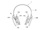
- FIG. 1 is a front view of a headphone 1 according to the first embodiment.
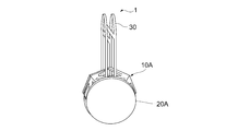
- FIG. 2 is a top view of the headphone 1 in the first embodiment.
- FIG. 3 is a side view of the headphone 1 in the first embodiment.
- the headphone 1 has a pair of ear accommodating portions 10A and 10B, a pair of housings 20A and 20B, an arm 30, and a cable 40.
- the ear housing portion 10A includes a frame 12A that surrounds the wearer's ear and contacts the head, connects the frame 12A and the housing 20A, covers the ear, and includes a connection portion 14A that is air permeable to the ear.
- the ear housing portion 10B includes a frame 12B and a connection portion 14B.
- the frame 12 and the connecting portion 14 are, for example, the same member, but may be different members.
- the connecting portion 14 is connected to the housing 20 at a central portion of the housing 20, for example. Thereby, the ear
- the connection part 14 of the ear accommodating part 10 includes a structure that covers the ear and has air permeability to the ear. Moreover, as a shape of the structure of the ear accommodating part 10, the surface which opposes the housing 20, for example is convex. In the example shown in FIGS. 1 to 3, the shape of the ear accommodating portion 10 is a saddle shape or a polygonal pyramid shape as an example of a convex shape.
- edge accommodating part 10 or the connection part 14 can cover an ear, and should just have air permeability, a dome shape, a cone shape, a truncated cone shape, a polygonal truncated cone shape, a columnar shape (cylindrical shape), It may be a polygonal column shape.
- connection portion 14 of the ear accommodating portion 10 includes a mesh structure having a plurality of holes or openings substantially uniformly.
- the ear container 10 includes a frame structure having a plurality of gaps.
- the size of the hole or opening may be any size as long as air permeability to the ear can be secured.
- the overall design of the headphone 1 can be improved.
- the structures and shapes of the ear accommodating portions 10A and 10B may be the same or different.
- the shape of the entire conventional headphone is determined to some extent, and in particular, in the conventional earpad corresponding to the ear accommodating portion 10 of the first embodiment, there are not many novel designs.
- the structure of the ear accommodating portion 10 in the structure of the ear accommodating portion 10, it is possible to accommodate the ear and further improve the design in shape while having air permeability.
- edge accommodating part 10 has a difference in size, it has a triangular shape, for example, and can give a sense of unity in design.
- the holes or openings may be provided substantially uniformly with respect to the entire circumference of the ear accommodating portion 10. Thereby, the wearer can hear the external sound naturally.
- the ear accommodating part 10 is designed so that the entire ear is accommodated in the accommodating space in the ear accommodating part 10 when the ear accommodating part 10 is mounted on the head surrounding the ear. Therefore, the ear accommodating portion 10 is basically designed so as not to contact the ear. However, the ear container 10 does not need to be in contact with everyone's ears. For example, when a person with large ears wears the ear container 10, the ear container 10 may slightly touch the ears or It may protrude from the hole or opening.
- the housing 20 includes a speaker unit therein, and is a case for protecting the speaker unit, and is connected to the ear housing 10.
- the speaker unit preferably includes, for example, a planar speaker unit, and further applies a speaker unit with improved directivity.
- the speaker unit may be arranged in the housing 20 in consideration of the position of the speaker unit so that the directivity of the output sound from the speaker unit is directly directed to the ear canal of the ear.
- the speaker unit is arranged so that sound is output from the central portion of the housing 20.
- the output sound goes directly to the ear canal of the ear, so that the sound leaking from the hole or opening of the ear housing 10 can be made as small as possible.
- the speaker unit may be a known technique or a commercially available one.
- the housing 20 includes various parts such as a power source, for example. Details of the inside of the housing 20 will be described with reference to FIG.
- the shape of the housing 20 has, for example, a convex shape on the surface facing the ear accommodating portion 10.
- the housing 20 has a bowl shape or a truncated cone shape as an example of a convex shape.
- the housing 20 may have a dome shape, a conical shape, a polygonal pyramid shape, a polygonal frustum shape, a columnar shape (cylindrical shape), a polygonal prism shape, or the like.
- the housing 20 may be, for example, an open type or a sealed type, and may have a structure in which sound leakage does not easily occur from the housing 20 to the outside. Further, the housing 20 has a convex shape as in the case of the ear accommodating portion 10, and the housing 20 and the ear accommodating portion 10 are connected in a substantially plane symmetry, so that a beautiful design impression can be given.
- the arm 30 is a part that supports the housing 20 and the like, and is also a part that creates a lateral pressure of the headphones 1.
- the arm 30 has flexibility so as to follow the shape of the wearer's head, and has a slide mechanism that adjusts the length of the arm 30.
- the arm 30 has a shape in which a gap is provided in the central portion, and may be formed, for example, from two parallel rod-shaped frames.
- it is desirable that the ear accommodating portion 10 is not greatly deformed by receiving a side pressure by the arm 30 at the time of wearing.
- the arm 30 connects the pair of housings 20 to each other.
- the arm 30 is connected to the ear accommodating part 10 or the housing 20.
- a part around the end of the arm 30 is connected to the convex part (tip part) of each of the ear accommodating part 10 and the housing 20. Is done.
- a slide mechanism for adjusting the length is provided at this portion. This slide mechanism will be described later.
- the cable 40 is, for example, a flexible cable, and has a length of 300 mm as an example and a width of 15 to 20 mm as an example.
- the cable is connected by a connector in each housing.
- the cable 40 transmits various signals (for example, sound signals) to the left and right speaker units.
- the cable 40 is not shown in FIG.
- FIG. 4 is an enlarged view seen from the inner side (ear side) of the ear accommodating portion 10B and the housing 20B.
- the total area of the plurality of hole portions or opening portions is sufficiently larger than the total area of the material of the ear accommodating portion.
- the air permeability around the ear is improved, and it is possible to prevent the ear from being steamed or sweating when the ear container 10 is attached.
- the total area of the hole portion or the opening portion is about 70%, and the total area of the material is about 30%.
- the present invention is not limited to the example shown in FIG.
- the ear accommodating portion 10B and the housing 20B are connected to each other at the convex tip portion 16B (convex tapering portion) of the ear accommodating portion 10B.
- the speaker unit 50B is connected so that the direction of the sound output from the unit 50B faces the ear canal direction of the ear.
- connection portion 14B is a portion that connects the frame 12B and the housing 20B.
- the tip portion 16B of the connection portion 14B is connected to the housing 20B.
- a substantially vertical cross section from the head direction to the housing 20 ⁇ / b> B direction will be described with respect to the structure of the ear housing portion 10 ⁇ / b> B.
- the frame 12B that contacts the head is, for example, an octagon
- the tip portion 16B connected to the housing 20B is, for example, a circle.
- the shape of the connecting portion 14B between the octagon and the circle is, for example, a square. It has become.
- the ear accommodating portion 10B has a frame structure in which an octagonal corner is connected to a square corner by a rod-shaped member, and a circle is divided into four parts from the square corner by a rod-shaped member. That is, as shown in FIG. 4, the ear container 10 ⁇ / b> B has a multi-layer structure, and connects from a predetermined position of a predetermined layer to a predetermined position of another layer in the outer frame of each layer. A rod-shaped member is included. Thereby, in the ear accommodating part 10B, it is easy to form an accommodating space, and the strength of the ear accommodating part 10B can be efficiently maintained.
- This frame structure may have a gap and may be molded integrally with resin or may be molded by partially assembling. Moreover, the relationship between the octagonal area> the square area> the circular area is established in the ear accommodating portion 10B. In addition, the outer frame from the octagon to the circle has a dome shape so that the ear can be covered.
- the structure of the ear container 10 shown in FIGS. 1 to 4 is merely an example, and may be another frame structure having a gap so that air flows between the outside and the inside of the ear container 10. .
- the slide mechanism 60 ⁇ / b> B of the arm 30 has a mechanism that slides at the tip portion (convex portion).
- the slide mechanism 60B sandwiches the gap at the central portion of the arm 30 in the connection portion (convex portion) between the housing 20B and the ear accommodating portion 10B so that the connection portion can easily slide through the gap.
- the slide mechanism 60B includes a locking mechanism for locking at the slid predetermined position. Therefore, the gap extending over the entire center of the arm 30 can enhance design and facilitate flexibility, and can serve as a part of the slide mechanism.
- a first switch 70 and a second switch 80 are provided on the inner side (ear side) of the housing 20B.
- the first switch 70 is, for example, a power switch, and switches a power ON / OFF switch of the headphones 1.
- the second switch 80 is a switch for adjusting the volume of the speaker unit 50B, and it is sufficient that the user can appropriately select a plurality of output levels.
- the button example shown in FIG. 4 is merely an example, and is not limited to this example.
- FIG. 5 is a diagram showing an example of the configuration inside the housing 20.
- the thickness of the substrate in the housing 20 is, for example, within 5 mm. Thereby, the thickness of the housing 20 can be reduced, and a stylish impression can be given in design.
- the diameter of the housing 20 is 80 mm, for example.
- the housing 20A includes a processing unit 100, an amplification unit 102A, a first communication unit 104, a light emitting unit 106A, and a speaker unit 50A.
- the processing unit 100 is a CPU (Central Processing Unit), for example, which converts a sound signal from a digital signal to an analog signal, performs verification processing on information extracted from the acquired sound signal, and emits light from the light emitting unit 106A. Or control.
- CPU Central Processing Unit
- the amplifying unit 102A amplifies the sound signal processed in the processing unit 100, and outputs the amplified signal to the speaker unit 50A. Thereby, a sound is output from the speaker unit 50A.
- the first communication unit 104 is a module having a wired or wireless communication function, for example, and communicates various signals.
- the first communication unit 104 is preferably communicated by a wireless communication function.
- the first communication unit 104 communicates with an information processing apparatus including a mobile terminal such as a PC (Personal Computer) or a smartphone, another headphone 1, or the like.
- the first communication unit 104 can synchronize and output sound to be communicated in the plurality of headphones 1.
- the first communication unit 104 can perform short-range wireless communication using 2.4 GHz, and can appropriately switch between the transmission mode and the reception mode.
- the first communication unit 104 will be described with an example of performing this short-range wireless communication.
- the light emitting unit 106A emits light such as an LED, for example, and may be provided at the peripheral edge in the housing 20A. For example, four LEDs are arranged at the periphery so that the intervals are equal. Based on the light emission control signal, the light emitting unit 106A can perform light control in accordance with sound, or perform light effects in combination with the plurality of headphones 1.
- the housing 20A may have a headphone jack having a diameter of 3.5 mm, for example, although not shown.
- the housing 20B includes a first switch 70, a second switch 80, an amplification unit 102B, a light emitting unit 106B, a power supply circuit 108, a charge protection circuit 110, a second communication unit 112, a battery 114, and a speaker unit 50B. including.
- the first switch 70 is, for example, a switch that turns the power on or off.
- the second switch 80 is a switch that adjusts the volume output from the speaker unit, for example.
- the amplifying unit 102B amplifies the sound signal acquired from the cable 40 and outputs the amplified sound signal to the speaker unit 50B. Thereby, a sound is output from the speaker unit 50B.
- the light emitting unit 106B is basically the same as the light emitting unit 106A.
- the light emitting unit 106B may be issued and controlled in synchronization with the light emitting unit 106A.
- the power supply circuit 108 is a power circuit that generates output power required from input power.
- the charge protection circuit 110 protects the battery 114 from overcharge, overdischarge, and overcurrent.
- the battery 114 is, for example, a lithium ion polymer secondary battery.
- the second communication unit 112 is a module having a function of performing wireless communication.
- the second communication unit 112 is a module having a wireless communication function based on Bluetooth (registered trademark). Accordingly, the second communication unit 112 can communicate with a device having a wireless communication function of the same standard.
- the second communication unit 112 can communicate with a mobile terminal, a PC, or the like.
- the housing 20B may have a micro USB connector. Further, the configuration of the housing 20A and the housing 20B shown in FIG. 5 is not limited to the above-described example, but may be appropriately changed in design according to the size and function in the housing. In addition, since the thickness of the central portion of the housing 20 shown in FIGS. 1 to 4 is the thickest, it is preferable to place a part having a height in the central portion of the housing 20.
- the material of the ear container 10 is a material using a resin such as silicon, Ultem, TR90, for example.
- a material of the ear accommodating portion 10 a material such as silicon wrapping on a material using a shape memory alloy (NT alloy) or the like can be used.
- the ear accommodating portion 10 may use a characteristic honeycomb structure or a hold technique.
- the ear accommodating portion 10 As described above, in the first embodiment, by having the above-described configuration of the ear accommodating portion 10, it is possible to ensure the breathability of the entire ear portion at the time of wearing. Occurrence can be suppressed. In the first embodiment, the wearer is less likely to sweat his / her ears when worn, so he can listen to music and the like for a long time. Further, in the first embodiment, the ear accommodating portion 10 is configured to contact the head around the ear and not to apply pressure to the ear when worn, and thus the ear is less likely to hurt even when worn for a long time. Moreover, in 1st Embodiment, the headphones 1 which were excellent in design can be provided by having the structure of the ear
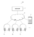
- FIG. 6 is a diagram illustrating an example of a configuration of the distribution system 200 according to the second embodiment.
- headphones 1A, 1B, and 1C an information processing apparatus 2, and a server 3 are connected via a communication network N.
- one information processing apparatus 2 is described, but there may be one information processing apparatus 2 that corresponds one-to-one for each headphone.
- the communication network N is configured by a wireless network or a wired network.
- Examples of communication networks include mobile phone networks, PHS (Personal Handy-phone System) networks, wireless LAN (Local Area Network), 3G (3rd Generation), LTE (Long Term Evolution), 4G (4th Generation), WiMax. (Registered Trademark), infrared communication, Bluetooth (Registered Trademark), wired LAN, telephone line, power line network, IEEE 1394, and other networks.
- the headphones 1A, 1B, and 1C are referred to as headphones 1 when they do not need to be distinguished from each other.
- the headphones 1 are the same as the headphones described in the first embodiment.
- the information processing device 2 is a personal computer such as a PC or a smartphone, or an information processing device having a communication function.
- the information processing apparatus 2 transmits a control signal or sound data to each headphone 1 via the communication network N.
- the server 3 distributes event information using the headphones 1, receives event registration from the information processing apparatus 2, and distributes an application for using the headphones 1 to the information processing apparatus 2.
- the distribution system 200 in the second embodiment can provide an event such as a silent disco that dances while listening to music with wireless headphones (headphones 1).
- FIG. 7 is a diagram illustrating an example of a functional configuration of the headphones 1 according to the second embodiment.
- the headphone 1 includes a first acquisition unit 302, a first pairing unit 304, an event control unit 306, a light emission control unit 308, and an output control unit 310.
- the 1st acquisition part 302, the 1st pairing part 304, the event control part 306, the light emission control part 308, and the output control part 310 may be implement
- the first acquisition unit 302 acquires various signals received from other devices. For example, the first acquisition unit 302 acquires a sound signal, a light emission control signal, an event ID, frequency information to which the sound signal is distributed, information on pairing, and the like from the information processing device 2 or other headphones 1. To do.
- a predetermined headphone may be set as a parent, and the other headphones may be set as a child.
- the parent headphones can simultaneously transmit music and the like to the child headphones.
- the first pairing unit 304 acquires information related to pairing from the first acquisition unit 302, for example, shared secret key information (link key) and a session key generated from the link key, and uses these information, Perform pairing.
- shared secret key information for example, shared secret key information (link key) and a session key generated from the link key
- the first pairing unit 304 performs pairing with the information processing apparatus 2 using Bluetooth (registered trademark). As a result, master-slave communication is established between the headphones 1 and the information processing apparatus 2. A known technique may be used for the pairing method. Using the communication established by the pairing, the first acquisition unit 302 may acquire an event ID and frequency information used for the event.
- Bluetooth registered trademark
- the first acquisition unit 302 may acquire an event ID and frequency information used for the event.
- the event control unit 306 acquires the event ID and frequency information of the event from the first acquisition unit 302 after pairing.
- the event control unit 306 sets the frequency at which the sound signal is distributed in the event based on the frequency information.
- the event control unit 306 may output a light emission control signal to the light emission control unit 308 to emit light indicating a receivable state.
- the event control unit 306 holds the event ID acquired immediately after pairing.
- the event control unit 306 controls events related to the headphones 1 using the event ID and the like.
- the event control unit 306 controls an event such as a silent disco using the headphones 1.
- the event control unit 306 obtains a sound signal that is transmitted in this event and in which an event ID is embedded in a non-audible area of the sound signal every predetermined time. To do.
- the predetermined time is, for example, 2 minutes.
- the event control unit 306 performs collation using the event ID extracted from the sound signal and the held event ID.
- the event control unit 306 controls the output control unit 310 to continue reproducing the sound signal when the event ID is collated.
- the sound signal includes information or data such as music and voice. Further, the event control unit 306 controls to stop the reproduction of the sound signal by the output control unit 310 when the event ID is not collated.
- the music can be transmitted all at once, and the sound signal can be reproduced only with the specific headphones 1 for which the event ID has been successfully verified.
- the light emission control unit 308 acquires a light emission control signal from the first acquisition unit 302, and controls the light emission of the light emitting units 106A and 106B based on the light emission control signal. Thereby, for example, it becomes possible to make the headphones 1 emit light according to the sound. By transmitting one light emission control signal to the plurality of headphones 1, synchronized light emission can be performed in the plurality of headphones 1. As a result, it is possible to produce a space where a plurality of headphones 1 exist with light.
- the light emission control unit 308 controls the light emitting units 106A and B to emit light in the first color when the sound information can be transmitted, and the light emitting units 106A and B perform the second light emission when the sound signal can be received. Control to emit color.
- the case where the sound signal can be transmitted is, for example, the case where the first communication unit 104 is in the transmission mode, after the frequency for distributing the sound signal is determined, and the case where the sound signal can be received is, for example, 1 When the communication unit 104 is in the reception mode and the frequency at which the sound signal is distributed is set.
- the output control unit 310 acquires a sound signal from the first acquisition unit 302 and controls so that sound is output (reproduced) from the speaker units 50A and 50B. Further, the output control unit 310 stops the reproduction when the event control unit 302 instructs the stop of the reproduction.
- the output control unit 310 can control the output of sound signals other than events, and can control the output of sound signals input from the headphone jack or the output of sound signals received from the information processing apparatus 2. Or
- FIG. 8 is a diagram illustrating an example of a hardware configuration of the information processing apparatus 2 according to the second embodiment. 8 includes at least a control unit 402, a communication unit 404, a storage unit 406, and a power supply unit 408.
- the control unit 402 is, for example, a CPU, and executes a program developed on the memory to cause the information processing apparatus 2 to realize various functions.
- the control unit 402 manages sound information transmitted to the headphones 1 and manages events. Details of the control unit 402 will be described with reference to FIG.
- the communication unit 404 transmits and receives data via the communication network N, for example.
- the communication unit 404 transmits various signals processed by the control unit 402 to the headphones 1 and the like.
- the communication unit 404 receives a signal from the server 3 or the like.
- the storage unit 406 stores programs and various data, for example. In the various data, event information including an event ID used for the event, identification information of the headphones 1 and the like are stored.
- the storage unit 406 stores a sound signal of the sound source.
- the power supply unit 408 supplies power to each unit.
- FIG. 9 is a diagram illustrating an example of a functional configuration of the information processing apparatus 2 according to the second embodiment.
- the information processing apparatus 2 includes a second acquisition unit 502, a second pairing unit 504, an event management unit 506, a light emission management unit 508, and an output management unit 510.
- the second acquisition unit 502, the second pairing unit 504, the event management unit 506, the light emission management unit 508, and the output management unit 510 can be realized by the control unit 402 shown in FIG.
- the second acquisition unit 502 acquires various signals and various information received from the server 3 and the headphones 1. For example, the second acquisition unit 502 acquires event information from the server 3, acquires a sound signal, acquires the identification number of the headphones 1 from the headphones 1, and acquires information related to pairing. .
- the second pairing unit 504 acquires information related to pairing from the second acquisition unit 502, for example, shared secret key information (link key) and a session key generated from the link key, and uses these information, Perform pairing. For example, when the pairing button on the screen is pressed, the second pairing unit 504 starts pairing. At this time, the information processing apparatus 2 may generate shared secret key information or may use predetermined shared secret key information.
- shared secret key information link key
- a session key generated from the link key For example, when the pairing button on the screen is pressed, the second pairing unit 504 starts pairing.
- the information processing apparatus 2 may generate shared secret key information or may use predetermined shared secret key information.
- the second pairing unit 504 performs pairing with the headphones 1 using Bluetooth (registered trademark). As a result, master-slave communication is established between the headphones 1 and the information processing apparatus 2.
- the event management unit 506 generates an event ID and manages an event related to the headphones 1 using the generated event ID and the like.
- the event management unit 506 of the information processing apparatus 2 for the parent headphones 1 manages events such as silent disco using the headphones 1. More specifically, the event management unit 506 may determine at which frequency the sound signal is transmitted, or may embed an event ID in the sound signal.
- the event management unit 506 embeds an event ID at regular intervals as a modulation signal such as DTMF (Dual Tone Multiple Frequency) in the non-audible region of the sound signal.
- the event ID may be embedded when the event control unit 306 of the parent headphone 1 transmits a sound signal.
- the event management unit 506 of the information processing apparatus 2 corresponding to the child headphone 1 controls to transmit the event ID and frequency information acquired from the server 3 or the like to the paired headphones 1. Thereby, the child headphone 1 can acquire the event ID used for collation before receiving the sound signal, and can set the frequency band to be distributed.
- the event is obtained when the parent headphones 1 that have received the sound signal transmit the sound signals to the child headphones 1 all at once and are legally purchased. Only the specific headphone 1 having the ID can reproduce the sound signal.
- the event management unit 506 enables the user to generate an event, and uploads event information generated by the user to the server 3. Thereby, it is possible to browse event information from the server 3 in the other information processing apparatus 2. Further, the event management unit 506 controls to connect to a purchase site as appropriate for ticket sales in an event. The event management unit 506 acquires an event ID and frequency information from the server 3 and the like after purchasing a ticket.
- the light emission management unit 508 generates and manages a light emission control signal according to the sound signal.
- the generated light emission control signal is transmitted to the headphones 1.
- the output management unit 510 acquires a sound signal from the event management unit 506 and manages it so as to output it to the headphones 1. For example, the output management unit 510 manages sound signals to be output according to events.
- the sound signal transmitted by the information processing device 2 can be transmitted to a large number of headphones 1, and one sound signal can be reproduced by a plurality of headphones 1. Therefore, in the second embodiment, an event such as a silent disco can be realized.
- the output management unit 510 may manage a playlist of sound signals stored in the storage unit 406 and output the sound signals selected by the user to the headphones 1.
- the hardware configuration of the server 3 is the same as that of the information processing apparatus 2 shown in FIG.
- the server 3 uploads event information generated by the information processing apparatus 2 or the like, and enables the event information to be searched. Further, in the case of a paid event, the server 3 connects to a purchase site and enables the purchase of a paid event ticket.
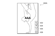
- FIG. 10 is a diagram illustrating an example of a home screen when an application for controlling the headphones 1 is activated on the information processing apparatus 2.
- an image indicating home On the screen 600A shown in FIG. 10, an image indicating home, a first search button 602, a second search button 604, an event creation button 606, and a setting button 608 are displayed.
- the first search button 602 is a button for searching for events and music.
- the second search button 604 is a button for searching for an event capable of receiving a sound signal at the current position and displaying event information.
- the event creation button 606 is a button for creating an event.
- a setting button 608 is a button for performing user registration and settings related to the headphones 1.
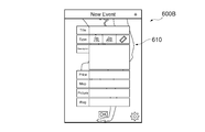
- FIG. 11 is a diagram showing an example of an event creation screen.
- the screen 600B shown in FIG. 11 is displayed when the event creation button 606 is pressed, and displays input fields such as an event title, type, description, price, and location. The user can create an event by inputting in these input fields.
- the creation of the event is completed, and the created event information is uploaded to the server 3 or predetermined user information. Or transmitted to the processing device 2.
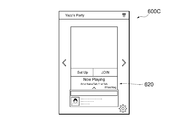
- FIG. 12 is a diagram showing an example of the event screen (part 1).
- a screen 600C shown in FIG. 12 is displayed when the second search button 604 is pressed, and a display area 620 showing an overview of the event is displayed.
- FIG. 13 is a diagram showing an example of the event screen (part 2).
- a screen 600D shown in FIG. 13 is displayed when the “Set Up” button on the screen shown in FIG. 12 is pressed, and a display area 630 showing the detailed information of the event is displayed.
- FIG. 14 is a diagram showing an example of the event screen (part 3).
- a screen 600E shown in FIG. 14 is displayed when the “JOIN” button on the screen shown in FIG. 12 is pressed, and a display area 640 for purchasing a ticket for the event is displayed.
- FIG. 15 is a diagram showing an example of the event screen (part 4).
- a screen 600F illustrated in FIG. 15 is one of the screens that are displayed after Hashtag is selected from the screen illustrated in FIG. In the screen 600F shown in FIG. 15, it is possible to receive social networking service between event participants. Thereby, communication between participants can be aimed at.
- FIGS. 18 to 20 illustrate processing related to events.
- FIG. 16 is a flowchart showing an example of music distribution processing on the transmission side.
- the transmission side for example, the information processing apparatus 2 performs pairing with the corresponding parent headphone 1.
- a known method may be used as the pairing method.
- step S104 the information processing apparatus 2 transmits the ON AIR mode to the headphones 1.
- the ON AIR mode for example, Bluetooth (registered trademark) is used.
- the parent headphone 1 is set to the transmission mode.
- step S106 the parent headphone 1 simultaneously distributes the sound signal of the music to the child headphone 1 existing within the communication range of the second communication unit 112.
- FIG. 17 is a flowchart showing an example of music reception processing on the receiving side.
- the receiving side for example, the headphone 1 performs pairing with the corresponding information processing apparatus 2.
- a known method may be used as the pairing method.
- step S204 the child headphone 1 receives the ON AIR mode from the information processing apparatus 2.
- the information processing apparatus 2 for example, Bluetooth (registered trademark) is used.
- the child headphones 1 are set to the reception mode.
- step S206 the child headphone 1 receives the music sound signal from the parent headphone 1. At this time, if the event ID is included in the sound signal, the child headphone 1 extracts the event ID and performs a matching process.
- step S208 the child headphone 1 reproduces the sound signal.
- a plurality of headphones 1 can reproduce one piece of music synchronously, and a silent disco or the like can be realized.
- FIG. 18 is a flowchart showing an example of processing related to event creation.
- the information processing apparatus 2 creates an event (see, for example, FIG. 11).
- step S304 the information processing apparatus 2 acquires an event ID for distinguishing the event when the event is created. Thereafter, the information processing apparatus 2 stores event information including the event ID in the server 3 or the local memory.
- step S306 the information processing apparatus 2 distributes the created event.
- Event distribution is performed by push communication or notification at a predetermined site. Thereby, the user can create an event and distribute the event.
- FIG. 19 is a flowchart showing an example of processing related to event participation.
- the information processing apparatus 2 registers the identification information of the corresponding headphone 1 in the application. Note that this processing is not necessary if the identification information of the headphones 1 has already been registered.
- step S404 the information processing apparatus 2 searches for events registered in the server 3 or the local memory.
- step S406 when the searched event is a paid event, the information processing apparatus 2 purchases a ticket by a user operation (see, for example, FIG. 14). This makes it possible to participate in the event. In the case of a free event, step S406 is not necessary.
- FIG. 20 is a flowchart showing an example of music playback processing in an event.
- step S ⁇ b> 502 shown in FIG. 20 the child headphone 1 receives a sound signal from the parent headphone 1.
- step S504 the child headphone 1 reproduces the acquired sound signal.
- step S506 the child headphone 1 extracts the event ID from the sound signal.
- step S508 the child headphone 1 performs a matching process using the extracted event ID. If the collation is successful (step S508-YES), the process returns to step S502. If the collation fails (step S508-NO), the process proceeds to step S510.
- step S510 the child headphone 1 stops receiving the sound signal or stops reproducing the sound signal. Thereby, it becomes possible to permit the reproduction of music only to the specific headphones 1. Note that the matching process is not always necessary, and in the case of a free event, the headphones 1 may be able to play the received music as it is.
- the distribution system 200 in the second embodiment can use the headphones 1 in a predetermined event.
- the headphones 1 can be used for events such as silent disco.
- the light emitting function of the headphones 1 it is possible to perform light emission control of the headphones 1 existing in the venue, produce a space, and excite the venue.
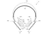
- FIG. 21 is a front view of the headphone 2 in the third embodiment.
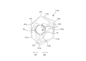
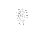
- FIG. 22 is a front view of the ear container 710A.
- FIG. 23 is a right side view of the ear housing portion 710A.
- the frames 712A and 712B that come into contact with the heads of the ear accommodating portions 710A and 710B have a shape along the skull or the head shape.
- the standard shape is expressed by 3D data, and the shapes of the frames 712A and 712B may be designed and formed using the 3D data. Accordingly, when the user wears the headphones 2, for example, the entire frame 712A is likely to come in contact with the skull or the head shape, so that the force pressing the periphery of the ear by the frame 712A is dispersed throughout the frame 712A. be able to.
- the ear accommodating portion 710A in the third embodiment disperses the force that presses the periphery of the ear, and closes the speaker as close to the ear as possible in order to prevent sound leakage, and vents similarly to the first embodiment. Designed to maintain strength while maintaining properties.
- the headphone 2 has a pair of ear accommodating portions 710A and 710B, a pair of housings 720A and 720B, an arm A730, and an arm B735.
- the configurations other than the ear accommodating portions 710A and 710B, the arm A730, and the arm B730 in the third embodiment are the same as the corresponding configurations in the first embodiment.
- the arm A730 has an arc shape along the top of the wearer's head, and is formed using a member having a cushioning property, for example.
- the arm B735 is provided, for example, outside the arm A730. Also, the arm B 735 generates a force F on the side that presses the ear when the headphone 2 is spread in a direction away from the ear in order to fit the headphone 2 to the ear. That is, the arm B 735 generates a force F in a direction in which the pair of ear housing portions 710A and 710B face each other when the pair of ear housing portions 710A and 710B are moved in a direction away from each other.
- the arm B735 is formed using, for example, an elastic member.
- the ear accommodating part 710 in 3rd Embodiment differs in the shape compared with the ear accommodating part 10 in 1st Embodiment.
- the ear accommodating portion 710 according to the third embodiment will be mainly described.
- the ear accommodating portions 710A and 710B have a plane-symmetric configuration, the ear accommodating portion 710A will be described as an example.
- the frame 712A of the ear accommodating portion 710A is composed of a frame-shaped member having vertices P11, P12, P13, P14, P15, and P16.
- a frame 712A including a member connecting these apexes has a shape along a skull or a head shape to which the headphones 2 are attached.
- the frame 712A has a hexagonal shape, and at least two vertices among the vertices are not on one plane. Thereby, the frame 712A can follow the uneven shape around the ear.
- the vertex P11 is located in the upper part of the ear when the headphones 2 are worn
- the vertex P12 is located in the upper part of the front of the ear when worn
- the vertex P13 is located in the lower part of the front of the ear when worn
- the vertex P14 is worn
- the apex P15 is located at the lower rear part of the ear at the time of wearing
- the apex P16 is located at the upper rear part of the ear at the time of wearing.
- the vertex P11 is located in the arm direction, and the vertex P14 is opposite to the arm. Located in the direction.
- the vertices P12 and P13 are located in front of the headphones 2 (frontal direction) from the reference lines of the vertices P11 and P14, and the vertices P15 and P16 are located behind the headphones 2 (in the direction of the back of the head).
- the vertex P13 is positioned above the same plane (the direction approaching the housing 700A is the upper direction) according to the convex shape of the cheekbones.
- the vertices P15 and P16 are positioned below the same plane (the direction away from the housing 700A is the lower side) according to the recess in the back of the ear. Further, the vertex P15 is located in a direction away from the same plane as the vertex P16.
- the structure of the frame 712A in the front view is a hexagon (see FIG. 22), and is positioned in the D2 direction from each line segment connecting the vertices P11, P12, P13, and P14 positioned in the D1 direction.
- the line segments that connect the vertices P11, P16, P15, and P14 are longer. That is, when the hexagon is divided by the line segment of the vertex P11 and the vertex P14, the areas of the quadrangles P11, P12, P13, and P14 are smaller than the areas of the quadrangles P11, P14, P15, and P16.
- the arrow D1 shown to FIG.22 and FIG.24 is a frontal direction
- the arrow D2 is a back part direction.
- the ear housing part 710A has a connection part 714A
- the connection part 714A has an attachment part 716A attached to the housing 700A.
- the attaching portion 716A has a ring shape in the example shown in FIG.
- the attachment portion 716A has claw portions T1, T2, and T3. The claw portions T1, T2, and T3 are fitted into recesses (not shown) of the housing 700A and are attached to the housing 700A by rotating.
- claw portions T1, T2, and T3 are not provided at ring-shaped uniform positions (for example, at intervals of 120 degrees), but are provided at random positions. This makes it possible to uniquely determine an appropriate mounting position of the ear accommodating portion 710A.
- the claw portions T1, T2, and T3 are fitted into the housing 700A, and are attached by rotating in the direction R1 (rotating right when viewed from the housing 700A side, and rotating left when viewed from the mounting side).
- the right ear receiving portion 710B it is attached by rotating counterclockwise when viewed from the housing 700B and clockwise when viewed from the attachment side. It has been found from experiments by the inventors that when a user wearing normal headphones exercises, the headphones (for example, the arm portion) often shift in the frontal direction D1.
- the ear accommodating portion 710A is rotated in a more tightening direction with respect to the housing 700A, thereby preventing the ear accommodating portion 710A from being detached from the housing 700A. Can do.
- connection portion 714A connects the frame 712A and the attachment portion 716A with a triangular rib structure. Thereby, when the headphones 2 are worn, the strength can be maintained while having air permeability around the ear.
- the apexes P21, P22, and P23 between the frame 712A and the attachment portion 716A for example, in the direction away from the housing 700A in the attachment portion 716A, the apexes P21 and P23 are provided closer to the attachment portion 716A than the vertex P22. It is done.
- Each of the vertices P11 to P16 described above is provided at a position further away from the housing 700A than the vertices P21 to P23.
- the mounting portion 716A is located inside the triangle formed by the vertices P21, P22, P23.
- Each vertex P21, P22, P23 is located inside the hexagonal frame 712A.
- the relationship between the lengths of the line segments is P23-P22 line segment> P22-P21 line segment ⁇ P21-P23 line segment.
- the rib is formed so as to go to the center of the mounting portion 716A.
- the relationship of the area of the mounting portion 716A ⁇ the area of the triangles P21, P22, P23 ⁇ the area of the frame 712A is established.
- the vertex P21 is provided at a position closest to the vertex P12
- the vertex P22 is provided at a position closest to the vertex P14
- the vertex P23 is closest to the vertex P16. Provided in position.
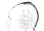
- the ear accommodating portion 710A is less likely to be displaced, so that a triangular rib structure connecting the vertices P11, P21, and P23 can be hooked on the ear (see FIG. 24). Thereby, the headphones 2 can be stably worn. Note that the triangle formed by these vertices P11, P21 and P23 is larger than the adjacent triangle. For this reason, it is easy for the ear to penetrate the triangular gap.
- the rib connecting the vertices P23 and P22, the rib connecting the vertices P22 and P21 (vertex located on the back side of P23 shown in FIG. 23), and the rib connecting the vertices P11 and P15 are: It is almost parallel. This is for the purpose of conforming to the shape of the ear when viewed from the back side of the ear when the headphones 2 are worn.
- the ear accommodating portion 710A can be closer to the ear.
- the vertices P21 and P23 are provided at a position closer to the attachment portion 716 than the vertex P22.
- FIG. 24 is a diagram showing the relationship between the ear accommodating part and the ear.
- the ear accommodating portion 710A is attached in a state of being closer to the ear E10.
- the speaker is provided at the center portion of the attachment portion 716A so that sound having directivity output from the speaker directly enters the back of the ear canal G10. Thereby, sound leakage can be prevented as much as possible.
- the ear accommodating portion 701A according to the third embodiment has a structure in which the ear accommodating portion 710A at the time of wearing does not shift in addition to the frame 712A pressing the ear peripheral portion evenly.
- the rib structure may be configured so that the peripheral edge of the ear is sandwiched in the gap between the vertices P22 and P23 and the mounting portion 716A. Thereby, the position shift of the ear accommodating portion 710A can be further prevented.
- the ear P14 is mounted such that the vertex P14 is inclined more in the F direction than the vertex P11.
- the position of the speaker may be adjusted so that the sound output from the speaker reaches the back of the ear canal G10.
- the fit of the ear container is further improved by the frame of the ear container along the skull or the head shape. be able to.
- sound leakage can be prevented as much as possible by adopting an ear housing structure that allows the speaker to be closer to the ear.
- a distribution device that distributes music may be provided at an event venue, and this distribution device may distribute sound signals of music to each headphone 1 via each information processing device 2. Further, the parent information processing device 2 distributes sound signals to other information processing devices 2 using a wireless network, and each information processing device 2 that has received the sound signals receives sound from the paired headphones 1. A signal may be transmitted.
- one piece of music can be provided in the venue.
- the distribution device or the parent information processing device 2 embeds the event ID in the sound signal and distributes it, so that the headphones 1 that have acquired the event ID along with the ticket purchase can reproduce the sound signal. Can be.
- the program of the information processing apparatus 2 of the present invention can be installed on a computer by downloading it through various recording media such as an optical disk such as a CD-ROM, a magnetic disk, and a semiconductor memory, or via a communication network. Can be loaded.
- various recording media such as an optical disk such as a CD-ROM, a magnetic disk, and a semiconductor memory, or via a communication network. Can be loaded.
- unit does not simply mean a physical configuration, but also includes a case where the functions of the configuration are realized by software.
- functions of one configuration may be realized by two or more physical configurations, or functions of two or more configurations may be realized by one physical configuration.
- the “system” includes a system configured to provide a specific function to the user, which is configured by an information processing apparatus or the like. For example, it is configured by a server device, a cloud computing type, an ASP (Application Service Provider), a client server model, and the like, but is not limited thereto.
Landscapes
- Engineering & Computer Science (AREA)
- Physics & Mathematics (AREA)
- Acoustics & Sound (AREA)
- Signal Processing (AREA)
- Multimedia (AREA)
- Headphones And Earphones (AREA)
Abstract
L'invention concerne un casque qui possède : une paire de logements contenant des unités haut-parleur ; des parties admission d'oreille qui contiennent des cadres entourant les oreilles et en contact avec la partie tête, et des parties connexion connectant les cadres et lesdits logements, recouvrant lesdites oreilles, et possédant une perméabilité à l'air vis-à-vis desdites oreilles ; et un bras qui connecte entre eux lesdits logements.
Priority Applications (4)
| Application Number | Priority Date | Filing Date | Title |
|---|---|---|---|
| JP2017517586A JP6488374B2 (ja) | 2015-05-13 | 2015-08-21 | ヘッドフォン |
| EP15891900.1A EP3297291A4 (fr) | 2015-05-13 | 2015-08-21 | Casque |
| US15/573,147 US10306345B2 (en) | 2015-05-13 | 2015-08-21 | Headphone |
| CN201580079788.2A CN107534806B (zh) | 2015-05-13 | 2015-08-21 | 头戴式耳机 |
Applications Claiming Priority (2)
| Application Number | Priority Date | Filing Date | Title |
|---|---|---|---|
| PCT/JP2015/063805 WO2016181531A1 (fr) | 2015-05-13 | 2015-05-13 | Casque |
| JPPCT/JP2015/063805 | 2015-05-13 |
Publications (1)
| Publication Number | Publication Date |
|---|---|
| WO2016181577A1 true WO2016181577A1 (fr) | 2016-11-17 |
Family
ID=57248718
Family Applications (2)
| Application Number | Title | Priority Date | Filing Date |
|---|---|---|---|
| PCT/JP2015/063805 Ceased WO2016181531A1 (fr) | 2015-05-13 | 2015-05-13 | Casque |
| PCT/JP2015/073559 Ceased WO2016181577A1 (fr) | 2015-05-13 | 2015-08-21 | Casque |
Family Applications Before (1)
| Application Number | Title | Priority Date | Filing Date |
|---|---|---|---|
| PCT/JP2015/063805 Ceased WO2016181531A1 (fr) | 2015-05-13 | 2015-05-13 | Casque |
Country Status (5)
| Country | Link |
|---|---|
| US (1) | US10306345B2 (fr) |
| EP (1) | EP3297291A4 (fr) |
| JP (2) | JP6488374B2 (fr) |
| CN (1) | CN107534806B (fr) |
| WO (2) | WO2016181531A1 (fr) |
Families Citing this family (5)
| Publication number | Priority date | Publication date | Assignee | Title |
|---|---|---|---|---|
| WO2016181531A1 (fr) * | 2015-05-13 | 2016-11-17 | Omotenasy合同会社 | Casque |
| US11805353B2 (en) | 2019-03-18 | 2023-10-31 | Sony Group Corporation | Headphone |
| CN111800702B (zh) * | 2020-07-29 | 2022-01-25 | 安徽金河电子科技有限公司 | 一种头戴式加固型耳机 |
| US20220239998A1 (en) * | 2021-01-28 | 2022-07-28 | Sony Interactive Entertainment LLC | Headphone ear pad to optimize comfort and maintain sound quality |
| US12192724B2 (en) | 2022-12-02 | 2025-01-07 | Htc Corporation | Head-mounted device |
Citations (6)
| Publication number | Priority date | Publication date | Assignee | Title |
|---|---|---|---|---|
| JPS5341219A (en) * | 1976-09-27 | 1978-04-14 | Matsushita Electric Ind Co Ltd | Sound insulation type headphone |
| JPH1032892A (ja) * | 1996-05-16 | 1998-02-03 | Sony Corp | 開放型ヘッドホン |
| JP2005311448A (ja) * | 2004-04-16 | 2005-11-04 | Sony Corp | ヘッドホン装置 |
| JP2011015338A (ja) * | 2009-07-06 | 2011-01-20 | Audio Technica Corp | イヤーマフ及びヘッドホン |
| JP2013251750A (ja) * | 2012-05-31 | 2013-12-12 | Sony Computer Entertainment Inc | ヘッドホン |
| WO2015045993A1 (fr) * | 2013-09-27 | 2015-04-02 | 株式会社村田製作所 | Casque d'écoute |
Family Cites Families (24)
| Publication number | Priority date | Publication date | Assignee | Title |
|---|---|---|---|---|
| JPS5410853B2 (fr) * | 1972-09-01 | 1979-05-10 | ||
| CA1032479A (fr) * | 1974-09-16 | 1978-06-06 | Rudolf Gorike | Ecouteur |
| JPS5487523A (en) * | 1977-12-23 | 1979-07-12 | Toshiba Corp | Headphone device |
| JPS5826281U (ja) * | 1981-08-11 | 1983-02-19 | 松下電器産業株式会社 | ヘツドホン |
| US4993074A (en) * | 1988-04-13 | 1991-02-12 | Carroll Robert J | Earphone spacer |
| JPH05130696A (ja) | 1991-10-31 | 1993-05-25 | Sony Corp | バイノーラル型コードレス補聴装置 |
| US5884998A (en) | 1996-10-02 | 1999-03-23 | Maxim Trucks | Front discharge transit mixer |
| GB9902442D0 (en) | 1999-02-05 | 1999-03-24 | New Transducers Ltd | A headphone |
| US20020131616A1 (en) | 2000-11-16 | 2002-09-19 | Bronnikov Andrei M. | Apparatus and methods for sound reproduction and recording |
| CN201185472Y (zh) * | 2008-04-22 | 2009-01-21 | 叶永富 | 改良的头戴式耳机结构 |
| CN201194429Y (zh) * | 2008-05-08 | 2009-02-11 | 颜聪裕 | 头戴式耳机 |
| JP5131096B2 (ja) * | 2008-09-02 | 2013-01-30 | ソニー株式会社 | ヘッドホン |
| JP2010263460A (ja) * | 2009-05-08 | 2010-11-18 | Audio Technica Corp | イヤーマフ及びヘッドホン |
| CN102487469B (zh) * | 2010-12-03 | 2014-07-09 | 深圳市冠旭电子有限公司 | 耳罩及头戴式降噪耳机 |
| JP2012249020A (ja) | 2011-05-26 | 2012-12-13 | Yamaha Corp | 音楽聴取支援装置 |
| CN103179480B (zh) * | 2011-12-26 | 2017-11-10 | 技嘉科技股份有限公司 | 耳机耳壳及耳机 |
| JP2013138350A (ja) | 2011-12-28 | 2013-07-11 | D & M Holdings Inc | ヘッドホン及びイヤーパッド |
| TWM436295U (en) * | 2012-04-18 | 2012-08-21 | Sound Team Entpr Co Ltd | Earphone mask |
| CN103475969B (zh) * | 2013-09-13 | 2018-01-09 | 青岛歌尔声学科技有限公司 | 一种具有照明功能的蓝牙耳机 |
| JP6085541B2 (ja) * | 2013-09-13 | 2017-02-22 | エムケー電子株式会社 | イヤースピーカ装置 |
| CN203827496U (zh) * | 2014-05-09 | 2014-09-10 | 曾光 | 一种多功能无线耳机 |
| CN204131679U (zh) * | 2014-06-17 | 2015-01-28 | 惠州市汇华科技有限公司 | 一种蓝牙耳机 |
| CN204291304U (zh) * | 2014-11-03 | 2015-04-22 | 才超 | 后挂项圈蓝牙耳机 |
| WO2016181531A1 (fr) * | 2015-05-13 | 2016-11-17 | Omotenasy合同会社 | Casque |
-
2015
- 2015-05-13 WO PCT/JP2015/063805 patent/WO2016181531A1/fr not_active Ceased
- 2015-08-21 WO PCT/JP2015/073559 patent/WO2016181577A1/fr not_active Ceased
- 2015-08-21 EP EP15891900.1A patent/EP3297291A4/fr not_active Withdrawn
- 2015-08-21 CN CN201580079788.2A patent/CN107534806B/zh not_active Expired - Fee Related
- 2015-08-21 US US15/573,147 patent/US10306345B2/en not_active Expired - Fee Related
- 2015-08-21 JP JP2017517586A patent/JP6488374B2/ja active Active
-
2018
- 2018-08-21 JP JP2018154546A patent/JP6618586B2/ja active Active
Patent Citations (6)
| Publication number | Priority date | Publication date | Assignee | Title |
|---|---|---|---|---|
| JPS5341219A (en) * | 1976-09-27 | 1978-04-14 | Matsushita Electric Ind Co Ltd | Sound insulation type headphone |
| JPH1032892A (ja) * | 1996-05-16 | 1998-02-03 | Sony Corp | 開放型ヘッドホン |
| JP2005311448A (ja) * | 2004-04-16 | 2005-11-04 | Sony Corp | ヘッドホン装置 |
| JP2011015338A (ja) * | 2009-07-06 | 2011-01-20 | Audio Technica Corp | イヤーマフ及びヘッドホン |
| JP2013251750A (ja) * | 2012-05-31 | 2013-12-12 | Sony Computer Entertainment Inc | ヘッドホン |
| WO2015045993A1 (fr) * | 2013-09-27 | 2015-04-02 | 株式会社村田製作所 | Casque d'écoute |
Non-Patent Citations (1)
| Title |
|---|
| See also references of EP3297291A4 * |
Also Published As
| Publication number | Publication date |
|---|---|
| JPWO2016181577A1 (ja) | 2018-02-22 |
| WO2016181531A1 (fr) | 2016-11-17 |
| CN107534806A (zh) | 2018-01-02 |
| JP2019004492A (ja) | 2019-01-10 |
| JP6618586B2 (ja) | 2019-12-11 |
| US20180206013A1 (en) | 2018-07-19 |
| CN107534806B (zh) | 2019-12-24 |
| EP3297291A1 (fr) | 2018-03-21 |
| EP3297291A4 (fr) | 2019-01-09 |
| JP6488374B2 (ja) | 2019-03-20 |
| US10306345B2 (en) | 2019-05-28 |
Similar Documents
| Publication | Publication Date | Title |
|---|---|---|
| JP6618586B2 (ja) | ヘッドフォン | |
| US20140347565A1 (en) | Media devices configured to interface with information appliances | |
| US20140342660A1 (en) | Media devices for audio and video projection of media presentations | |
| US9998848B2 (en) | System and method for making a quick connection between a smart mobile device and external audio speakers and video monitors using a connector pad | |
| US20140370817A1 (en) | Determining proximity for devices interacting with media devices | |
| CN104509129A (zh) | 耳机方位的自动检测 | |
| US20160029114A1 (en) | Wireless earphone set | |
| US11916988B2 (en) | Methods and systems for managing simultaneous data streams from multiple sources | |
| AU2014243721A1 (en) | Cloud-based media device configuration and ecosystem setup | |
| US10210739B2 (en) | Proximity-based control of media devices | |
| WO2017048853A1 (fr) | Système d'accessoires de cordon | |
| CN104254036A (zh) | 一种耳机 | |
| US9578407B2 (en) | Multi-mode audio device and monitoring system | |
| CN106603947A (zh) | 电视机伴音播放的控制方法及装置 | |
| US9936296B1 (en) | Device, system, and method for multimedia communications | |
| CN107371108A (zh) | 一种多声道扬声器系统及设备 | |
| CN105578329A (zh) | 头戴式耳机 | |
| CN108040314A (zh) | 一种可灵活配置的多声道的融合型智能音箱 | |
| CN117177129A (zh) | 音频播放装置、播放系统及音频播放方法 | |
| CN207947894U (zh) | 一种可灵活配置的多声道的融合型智能音箱 | |
| CN106878846B (zh) | 多轨立体声耳机结构 | |
| CN210807587U (zh) | 一种头戴式双声道耳机 | |
| WO2025041534A1 (fr) | Dispositif de communication et procédé de communication | |
| CN113545105A (zh) | 配备环绕立体声元件且装有扬声器组件单元的包耳式头戴耳机 | |
| AU2014203748A1 (en) | A headphone set and a connector therefor |
Legal Events
| Date | Code | Title | Description |
|---|---|---|---|
| 121 | Ep: the epo has been informed by wipo that ep was designated in this application |
Ref document number: 15891900 Country of ref document: EP Kind code of ref document: A1 |
|
| ENP | Entry into the national phase |
Ref document number: 2017517586 Country of ref document: JP Kind code of ref document: A |
|
| WWE | Wipo information: entry into national phase |
Ref document number: 15573147 Country of ref document: US |
|
| NENP | Non-entry into the national phase |
Ref country code: DE |