WO2016181755A1 - Pompe à carburant à haute pression - Google Patents
Pompe à carburant à haute pression Download PDFInfo
- Publication number
- WO2016181755A1 WO2016181755A1 PCT/JP2016/062050 JP2016062050W WO2016181755A1 WO 2016181755 A1 WO2016181755 A1 WO 2016181755A1 JP 2016062050 W JP2016062050 W JP 2016062050W WO 2016181755 A1 WO2016181755 A1 WO 2016181755A1
- Authority
- WO
- WIPO (PCT)
- Prior art keywords
- relief
- passage
- pressure
- fuel
- seat surface
- Prior art date
- Legal status (The legal status is an assumption and is not a legal conclusion. Google has not performed a legal analysis and makes no representation as to the accuracy of the status listed.)
- Ceased
Links
Images





Classifications
-
- F—MECHANICAL ENGINEERING; LIGHTING; HEATING; WEAPONS; BLASTING
- F02—COMBUSTION ENGINES; HOT-GAS OR COMBUSTION-PRODUCT ENGINE PLANTS
- F02M—SUPPLYING COMBUSTION ENGINES IN GENERAL WITH COMBUSTIBLE MIXTURES OR CONSTITUENTS THEREOF
- F02M63/00—Other fuel-injection apparatus having pertinent characteristics not provided for in groups F02M39/00 - F02M57/00 or F02M67/00; Details, component parts, or accessories of fuel-injection apparatus, not provided for in, or of interest apart from, the apparatus of groups F02M39/00 - F02M61/00 or F02M67/00; Combination of fuel pump with other devices, e.g. lubricating oil pump
- F02M63/02—Fuel-injection apparatus having several injectors fed by a common pumping element, or having several pumping elements feeding a common injector; Fuel-injection apparatus having provisions for cutting-out pumps, pumping elements, or injectors; Fuel-injection apparatus having provisions for variably interconnecting pumping elements and injectors alternatively
- F02M63/0225—Fuel-injection apparatus having a common rail feeding several injectors ; Means for varying pressure in common rails; Pumps feeding common rails
- F02M63/023—Means for varying pressure in common rails
- F02M63/026—Means for reducing the pressure in common rails at power off
-
- F—MECHANICAL ENGINEERING; LIGHTING; HEATING; WEAPONS; BLASTING
- F02—COMBUSTION ENGINES; HOT-GAS OR COMBUSTION-PRODUCT ENGINE PLANTS
- F02M—SUPPLYING COMBUSTION ENGINES IN GENERAL WITH COMBUSTIBLE MIXTURES OR CONSTITUENTS THEREOF
- F02M55/00—Fuel-injection apparatus characterised by their fuel conduits or their venting means; Arrangements of conduits between fuel tank and pump F02M37/00
- F02M55/02—Conduits between injection pumps and injectors, e.g. conduits between pump and common-rail or conduits between common-rail and injectors
-
- F—MECHANICAL ENGINEERING; LIGHTING; HEATING; WEAPONS; BLASTING
- F02—COMBUSTION ENGINES; HOT-GAS OR COMBUSTION-PRODUCT ENGINE PLANTS
- F02M—SUPPLYING COMBUSTION ENGINES IN GENERAL WITH COMBUSTIBLE MIXTURES OR CONSTITUENTS THEREOF
- F02M59/00—Pumps specially adapted for fuel-injection and not provided for in groups F02M39/00 -F02M57/00, e.g. rotary cylinder-block type of pumps
- F02M59/44—Details, components parts, or accessories not provided for in, or of interest apart from, the apparatus of groups F02M59/02 - F02M59/42; Pumps having transducers, e.g. to measure displacement of pump rack or piston
- F02M59/46—Valves
-
- F—MECHANICAL ENGINEERING; LIGHTING; HEATING; WEAPONS; BLASTING
- F02—COMBUSTION ENGINES; HOT-GAS OR COMBUSTION-PRODUCT ENGINE PLANTS
- F02M—SUPPLYING COMBUSTION ENGINES IN GENERAL WITH COMBUSTIBLE MIXTURES OR CONSTITUENTS THEREOF
- F02M59/00—Pumps specially adapted for fuel-injection and not provided for in groups F02M39/00 -F02M57/00, e.g. rotary cylinder-block type of pumps
- F02M59/44—Details, components parts, or accessories not provided for in, or of interest apart from, the apparatus of groups F02M59/02 - F02M59/42; Pumps having transducers, e.g. to measure displacement of pump rack or piston
- F02M59/46—Valves
- F02M59/462—Delivery valves
-
- F—MECHANICAL ENGINEERING; LIGHTING; HEATING; WEAPONS; BLASTING
- F02—COMBUSTION ENGINES; HOT-GAS OR COMBUSTION-PRODUCT ENGINE PLANTS
- F02M—SUPPLYING COMBUSTION ENGINES IN GENERAL WITH COMBUSTIBLE MIXTURES OR CONSTITUENTS THEREOF
- F02M63/00—Other fuel-injection apparatus having pertinent characteristics not provided for in groups F02M39/00 - F02M57/00 or F02M67/00; Details, component parts, or accessories of fuel-injection apparatus, not provided for in, or of interest apart from, the apparatus of groups F02M39/00 - F02M61/00 or F02M67/00; Combination of fuel pump with other devices, e.g. lubricating oil pump
- F02M63/0012—Valves
- F02M63/0031—Valves characterized by the type of valves, e.g. special valve member details, valve seat details, valve housing details
- F02M63/0033—Lift valves, i.e. having a valve member that moves perpendicularly to the plane of the valve seat
- F02M63/0036—Lift valves, i.e. having a valve member that moves perpendicularly to the plane of the valve seat with spherical or partly spherical shaped valve member ends
-
- F—MECHANICAL ENGINEERING; LIGHTING; HEATING; WEAPONS; BLASTING
- F02—COMBUSTION ENGINES; HOT-GAS OR COMBUSTION-PRODUCT ENGINE PLANTS
- F02M—SUPPLYING COMBUSTION ENGINES IN GENERAL WITH COMBUSTIBLE MIXTURES OR CONSTITUENTS THEREOF
- F02M63/00—Other fuel-injection apparatus having pertinent characteristics not provided for in groups F02M39/00 - F02M57/00 or F02M67/00; Details, component parts, or accessories of fuel-injection apparatus, not provided for in, or of interest apart from, the apparatus of groups F02M39/00 - F02M61/00 or F02M67/00; Combination of fuel pump with other devices, e.g. lubricating oil pump
- F02M63/0012—Valves
- F02M63/0031—Valves characterized by the type of valves, e.g. special valve member details, valve seat details, valve housing details
- F02M63/0054—Check valves
-
- F—MECHANICAL ENGINEERING; LIGHTING; HEATING; WEAPONS; BLASTING
- F02—COMBUSTION ENGINES; HOT-GAS OR COMBUSTION-PRODUCT ENGINE PLANTS
- F02M—SUPPLYING COMBUSTION ENGINES IN GENERAL WITH COMBUSTIBLE MIXTURES OR CONSTITUENTS THEREOF
- F02M63/00—Other fuel-injection apparatus having pertinent characteristics not provided for in groups F02M39/00 - F02M57/00 or F02M67/00; Details, component parts, or accessories of fuel-injection apparatus, not provided for in, or of interest apart from, the apparatus of groups F02M39/00 - F02M61/00 or F02M67/00; Combination of fuel pump with other devices, e.g. lubricating oil pump
- F02M63/0012—Valves
- F02M63/007—Details not provided for in, or of interest apart from, the apparatus of the groups F02M63/0014 - F02M63/0059
- F02M63/0077—Valve seat details
-
- F—MECHANICAL ENGINEERING; LIGHTING; HEATING; WEAPONS; BLASTING
- F02—COMBUSTION ENGINES; HOT-GAS OR COMBUSTION-PRODUCT ENGINE PLANTS
- F02M—SUPPLYING COMBUSTION ENGINES IN GENERAL WITH COMBUSTIBLE MIXTURES OR CONSTITUENTS THEREOF
- F02M63/00—Other fuel-injection apparatus having pertinent characteristics not provided for in groups F02M39/00 - F02M57/00 or F02M67/00; Details, component parts, or accessories of fuel-injection apparatus, not provided for in, or of interest apart from, the apparatus of groups F02M39/00 - F02M61/00 or F02M67/00; Combination of fuel pump with other devices, e.g. lubricating oil pump
- F02M63/0012—Valves
- F02M63/007—Details not provided for in, or of interest apart from, the apparatus of the groups F02M63/0014 - F02M63/0059
- F02M63/0078—Valve member details, e.g. special shape, hollow or fuel passages in the valve member
-
- F—MECHANICAL ENGINEERING; LIGHTING; HEATING; WEAPONS; BLASTING
- F02—COMBUSTION ENGINES; HOT-GAS OR COMBUSTION-PRODUCT ENGINE PLANTS
- F02M—SUPPLYING COMBUSTION ENGINES IN GENERAL WITH COMBUSTIBLE MIXTURES OR CONSTITUENTS THEREOF
- F02M63/00—Other fuel-injection apparatus having pertinent characteristics not provided for in groups F02M39/00 - F02M57/00 or F02M67/00; Details, component parts, or accessories of fuel-injection apparatus, not provided for in, or of interest apart from, the apparatus of groups F02M39/00 - F02M61/00 or F02M67/00; Combination of fuel pump with other devices, e.g. lubricating oil pump
- F02M63/02—Fuel-injection apparatus having several injectors fed by a common pumping element, or having several pumping elements feeding a common injector; Fuel-injection apparatus having provisions for cutting-out pumps, pumping elements, or injectors; Fuel-injection apparatus having provisions for variably interconnecting pumping elements and injectors alternatively
- F02M63/0225—Fuel-injection apparatus having a common rail feeding several injectors ; Means for varying pressure in common rails; Pumps feeding common rails
- F02M63/023—Means for varying pressure in common rails
- F02M63/0235—Means for varying pressure in common rails by bleeding fuel pressure
- F02M63/0245—Means for varying pressure in common rails by bleeding fuel pressure between the high pressure pump and the common rail
-
- F—MECHANICAL ENGINEERING; LIGHTING; HEATING; WEAPONS; BLASTING
- F02—COMBUSTION ENGINES; HOT-GAS OR COMBUSTION-PRODUCT ENGINE PLANTS
- F02M—SUPPLYING COMBUSTION ENGINES IN GENERAL WITH COMBUSTIBLE MIXTURES OR CONSTITUENTS THEREOF
- F02M63/00—Other fuel-injection apparatus having pertinent characteristics not provided for in groups F02M39/00 - F02M57/00 or F02M67/00; Details, component parts, or accessories of fuel-injection apparatus, not provided for in, or of interest apart from, the apparatus of groups F02M39/00 - F02M61/00 or F02M67/00; Combination of fuel pump with other devices, e.g. lubricating oil pump
- F02M63/02—Fuel-injection apparatus having several injectors fed by a common pumping element, or having several pumping elements feeding a common injector; Fuel-injection apparatus having provisions for cutting-out pumps, pumping elements, or injectors; Fuel-injection apparatus having provisions for variably interconnecting pumping elements and injectors alternatively
- F02M63/0225—Fuel-injection apparatus having a common rail feeding several injectors ; Means for varying pressure in common rails; Pumps feeding common rails
- F02M63/023—Means for varying pressure in common rails
- F02M63/0235—Means for varying pressure in common rails by bleeding fuel pressure
- F02M63/025—Means for varying pressure in common rails by bleeding fuel pressure from the common rail
-
- F—MECHANICAL ENGINEERING; LIGHTING; HEATING; WEAPONS; BLASTING
- F16—ENGINEERING ELEMENTS AND UNITS; GENERAL MEASURES FOR PRODUCING AND MAINTAINING EFFECTIVE FUNCTIONING OF MACHINES OR INSTALLATIONS; THERMAL INSULATION IN GENERAL
- F16K—VALVES; TAPS; COCKS; ACTUATING-FLOATS; DEVICES FOR VENTING OR AERATING
- F16K15/00—Check valves
- F16K15/02—Check valves with guided rigid valve members
- F16K15/04—Check valves with guided rigid valve members shaped as balls
- F16K15/044—Check valves with guided rigid valve members shaped as balls spring-loaded
-
- F—MECHANICAL ENGINEERING; LIGHTING; HEATING; WEAPONS; BLASTING
- F02—COMBUSTION ENGINES; HOT-GAS OR COMBUSTION-PRODUCT ENGINE PLANTS
- F02M—SUPPLYING COMBUSTION ENGINES IN GENERAL WITH COMBUSTIBLE MIXTURES OR CONSTITUENTS THEREOF
- F02M2200/00—Details of fuel-injection apparatus, not otherwise provided for
- F02M2200/04—Fuel-injection apparatus having means for avoiding effect of cavitation, e.g. erosion
-
- F—MECHANICAL ENGINEERING; LIGHTING; HEATING; WEAPONS; BLASTING
- F02—COMBUSTION ENGINES; HOT-GAS OR COMBUSTION-PRODUCT ENGINE PLANTS
- F02M—SUPPLYING COMBUSTION ENGINES IN GENERAL WITH COMBUSTIBLE MIXTURES OR CONSTITUENTS THEREOF
- F02M59/00—Pumps specially adapted for fuel-injection and not provided for in groups F02M39/00 -F02M57/00, e.g. rotary cylinder-block type of pumps
- F02M59/02—Pumps specially adapted for fuel-injection and not provided for in groups F02M39/00 -F02M57/00, e.g. rotary cylinder-block type of pumps of reciprocating-piston or reciprocating-cylinder type
- F02M59/025—Pumps specially adapted for fuel-injection and not provided for in groups F02M39/00 -F02M57/00, e.g. rotary cylinder-block type of pumps of reciprocating-piston or reciprocating-cylinder type characterised by a single piston
Definitions
- the present invention relates to a high pressure fuel pump, and more particularly to a high pressure fuel pump provided with a relief valve mechanism.
- the high-pressure pump described in Patent Document 1 includes a valve body and a seat portion that engages with the valve body and seats fuel in a relief passage that relieves high-pressure liquid from a high-pressure side to a low-pressure side. It is a separate part for the body.
- a slider is installed between the valve body and an elastic member that urges the valve body. Then, the sliding path is regulated by sliding the slider in the valve opening direction along the sliding inner wall. Accordingly, it is described that stress inclined with respect to the axis of the elastic member is not applied, the lift amount of the relief valve is stabilized, and the durability of the spring is improved.
- the conventional technology has the following problems.
- the relief valve of the high-pressure fuel pump has a function to suppress the occurrence of abnormal pressure where the discharge pressure becomes higher than the allowable value. Therefore, when the discharge pressure becomes higher than the set pressure, the valve body of the relief valve opens and the high pressure is released.
- valve body When the condition that the discharge pressure is below the permissible value is satisfied, the valve body must be seated on the seat and the fuel must be completely sealed.
- the valve element opens and part of the fuel passage when high pressure is released, the intersection of the seat surface and the passage hole is an edge on the high pressure side of the seat surface, high pressure fuel is released In some cases, fluid separation may occur at the edge portion. And when it becomes below the saturated vapor pressure of fuel, cavitation bubbles are generated. There is a risk that cavitation erosion may occur in which the sheet surface is damaged by energy generated when the generated cavitation bubbles collapse. When this damage progresses, there is a possibility that a gap is generated between the valve body and the seat and the fuel cannot be completely sealed.
- an object of the present invention is to provide a high-pressure fuel pump having a highly reliable relief valve mechanism that suppresses the occurrence of cavitation erosion on the seat surface of the relief valve mechanism.
- a pressurizing chamber for pressurizing fuel a discharge valve disposed on the downstream side of the pressurizing chamber, and fuel in a discharge passage on the downstream side of the discharge valve
- the relief valve mechanism is connected to the discharge passage and connected to the relief passage and connected to the relief passage.
- a relief seat surface that is enlarged toward the pressure chamber or the low-pressure passage, and a relief valve element that is positioned on the pressure chamber side or the low-pressure passage side of the relief seat surface and is seated on the relief seat surface
- the intersection of the relief passage and the relief sheet surface is located on the discharge passage side with respect to the end of the relief valve body on the discharge passage side.
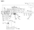
- FIG. 1 It is a figure explaining the whole block diagram of the fuel supply system which returns a high pressure fuel to a low pressure side by a relief valve mechanism. It is a figure explaining the whole fuel supply system block diagram which returns a high pressure fuel to the pressurization chamber side by a relief valve mechanism.
- FIG. It is sectional drawing of the relief valve mechanism of Example 1.
- FIG. It is sectional drawing of an example of a relief valve mechanism.
- It is a cross-sectional enlarged view of the relief valve mechanism of FIG. 3 is an enlarged view of a sheet portion according to Embodiment 1.
- FIG. It is an enlarged view of the seat part of the relief valve mechanism of FIG. It is a figure which shows the relief valve mechanism of Example 2.
- FIG. 1 It is a figure explaining the whole block diagram of the fuel supply system which returns a high pressure fuel to a low pressure side by a relief valve mechanism.
- FIG. 3 It is a figure explaining
- FIG. It is a figure which shows the relief valve mechanism of Example 3.
- FIG. It is a figure which shows the relief valve mechanism of Example 4.
- FIG. It is a graph which shows the relationship between (PHI) d / (PHI) D and the fuel pressure of a seat surface front-end
- FIG. 1 shows the overall configuration of a system that implements the present invention.
- a portion surrounded by a broken line in FIG. 1 shows a pump housing 1 of a high-pressure fuel supply pump, and a mechanism and parts shown in the broken line are integrally incorporated therein.
- the fuel in the fuel tank 20 is pumped up by the feed pump 21 and sent to the fuel inlet 10 a of the pump housing 1 through the suction pipe 28.
- the fuel that has passed through the fuel intake port 10a reaches the intake port 30a of the electromagnetic intake valve mechanism 30 that constitutes the variable capacity mechanism via the pressure pulsation reducing mechanism 9 and the intake passage 10c.
- the electromagnetic suction valve mechanism 30 includes an electromagnetic coil 30b, and in a state where the electromagnetic coil 30b is energized, the electromagnetic plunger 30c compresses the spring 33 and moves to the right in FIG. Maintained. At this time, the suction valve body 31 attached to the tip of the electromagnetic plunger 30c opens the suction port 32 leading to the pressurizing chamber 11 of the high-pressure fuel supply pump.
- the electromagnetic coil 30 b is not energized and there is no fluid differential pressure between the suction passage 10 c (suction port 30 a) and the pressurizing chamber 11, the suction valve body 31 is moved by the biasing force of the spring 33.
- the suction port 32 is urged in the valve closing direction (leftward in FIG. 1) to be closed, and this state is maintained.
- the suction valve body 31 is moved leftward in FIG. 1 by the urging force of the spring 33 that is constantly acting on the suction valve body 31 to close the suction port 32.
- the suction port 32 is closed, the fuel pressure in the pressurizing chamber 11 rises with the rise of the plunger 2 from this time.
- the fuel pressure in the pressurizing chamber 11 exceeds a pressure larger than the fuel pressure in the discharge port 13 by a predetermined value, the fuel remaining in the pressurizing chamber 11 is discharged via the discharge valve mechanism 8. High pressure discharge is performed and supplied to the common rail 23. This process is called a discharge process.
- the compression process of the plunger 2 includes a return process and a discharge process.
- the amount of high-pressure fuel discharged can be controlled by controlling the timing of releasing the energization of the electromagnetic coil 30c of the electromagnetic intake valve mechanism 30. If the timing of releasing the energization to the electromagnetic coil 30b is advanced, the ratio of the return process in the compression process is reduced and the ratio of the discharge process is increased. That is, the amount of fuel returned to the suction passage 10c (suction port 30a) is reduced and the amount of fuel discharged at high pressure is increased. On the other hand, if the timing of releasing the energization is delayed, the ratio of the return process in the compression process is increased and the ratio of the discharge process is decreased. That is, more fuel is returned to the suction passage 10c and less fuel is discharged at high pressure. The timing of releasing the energization is controlled by a command from the ECU.
- the ECU controls the timing of releasing the energization of the electromagnetic coil, whereby the amount of fuel discharged at a high pressure can be made the amount required by the internal combustion engine.
- a discharge valve mechanism 8 is provided on the outlet side of the pressurizing chamber 11 between the discharge port (discharge side pipe connection portion) 13.
- the discharge valve mechanism 8 includes a sheet member 8a, a discharge valve 8b, a discharge valve spring 8c, and a holding member (discharge valve stopper) 8d.
- the discharge valve 8b In a state where there is no fuel differential pressure between the pressurizing chamber 11 and the discharge port 13, the discharge valve 8b is pressed against the seat member 8a by the urging force of the discharge valve spring 8c and is in a closed state.
- the discharge valve 8b After the discharge valve 8b is opened, the operation is restricted when it comes into contact with the holding member 8d. Therefore, the stroke of the discharge valve 8b is appropriately determined by the holding member 8d. If the stroke is too large, the fuel discharged to the fuel discharge port 13 flows back into the pressurizing chamber 11 again due to the delay in closing the discharge valve 8b, so that the efficiency of the high-pressure pump decreases. . Further, when the discharge valve 8b repeats opening and closing movements, the holding member 8d guides the discharge valve so as to move only in the stroke direction. By configuring as described above, the discharge valve mechanism 8 becomes a check valve that restricts the flow direction of fuel.
- the fuel introduced to the fuel suction port 10a is pressurized to a required amount by the reciprocating motion of the plunger 2 in the pressurizing chamber 11 of the pump body 1, and the fuel discharge port 13 passes through the discharge valve mechanism 8.
- the common rail 23 which is a high-pressure pipe.
- the common rail 23 is provided with an injector 24 and a pressure sensor 26.
- the injectors 24 are mounted in accordance with the number of cylinders of the internal combustion engine, and the fuel is injected into the cylinders by operating the on-off valve according to the control signal of the ECU 27.
- the pump housing 1 is provided with a relief passage 300 that connects the discharge passage 12 and the suction passage 10c.
- the relief passage 300 restricts the flow of fuel in only one direction from the discharge passage 12 to the suction passage 10c.
- a valve mechanism 200 is provided.
- a pressurizing chamber 11 for pressurizing the fuel, a discharge valve mechanism 8 disposed on the downstream side of the pressurizing chamber 11, and fuel in the discharge passage 12 on the downstream side of the discharge valve mechanism 8 are returned to the suction passage 10c which is a low-pressure passage. And a relief valve mechanism.
- the fuel flow in the relief passage 300 may flow from the discharge passage 12 into the pressurizing chamber 11. That is, the relief valve mechanism 200 of this embodiment may return the fuel in the discharge passage 12 on the downstream side of the discharge valve mechanism 8 to the pressurizing chamber 11.
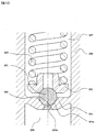
- FIG. 3 shows a cross section of the relief valve mechanism according to the first embodiment of the present invention.
- the relief valve mechanism 200 is formed to expand toward the pressurizing chamber 11 or the low-pressure passage (suction passage 10c) connected to the relief passage 208a and the relief passage 208a.
- a relief seat surface 204, and a relief valve body 201 that is positioned on the side of the pressure chamber 11 or the low-pressure passage (suction passage 10c) with respect to the relief seat surface 204 and is seated on the relief seat surface 204.
- the relief valve mechanism 200 includes a valve body retainer 202 that restrains the relief valve body 201, an elastic member 203 that urges the relief valve body 201 toward the discharge passage 12 (relief upstream side), an elastic member 203, and a valve body retainer 202.
- a housing 205 housed therein.
- the relief seat surface 204 has a seat portion 204a that engages with the relief valve body 201 to seal the fuel.
- On the upstream side of the relief valve body 201 there is a high pressure chamber 206 that is always in communication with the discharge passage 12, and on the downstream side of the relief valve body 201 is a pressure chamber 11 or a low pressure chamber 207 that is always in communication with the low pressure passage (suction passage 10c). It is formed.
- the relief passage 208 a is formed from the high pressure chamber 206 on the upstream side of the relief valve body 201 toward the relief seat surface 204.
- the relief valve body 201 is urged against the seat portion 204 a by the elastic member 203 against the pressure of the high-pressure fuel guided from the discharge flow path 12.
- the fluid force acting on the relief valve body 201 may exceed the urging force of the elastic member 203. Then, the relief valve body 201 leaves the seat portion 204a, the relief valve mechanism 200 is opened, and the relief passage is in a communicating state.
- the pressure in the high pressure chamber 206 decreases again, the urging force of the elastic member 203 exceeds the fluid force acting on the relief valve body 201, and the relief valve body 201 moves toward the seat portion 204a, Sit on the seat portion 204a.
- FIG. 4 shows a sectional view of an example of the relief valve mechanism.
- FIG. 6 is an enlarged sectional view of the relief valve mechanism of FIG.
- the sheet surface front end 208 on the inner peripheral side of the relief sheet surface 204 is formed at a position close to the sheet portion 204a.
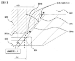
- the present inventors have intensively studied and found that cavitation and erosion occur at the front end 208 of the sheet surface according to the structure shown in FIG.
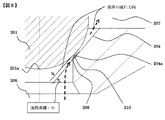
- FIG. 8 shows a state in which cavitation occurs at the front end 208 of the sheet surface.
- the relief valve body 201 is The seat 204a formed on the relief seat surface 204 is opened and the valve is opened, and the relief passage is in a communicating state. Then, the high-pressure fuel passes through the relief passage 208a from the high-pressure chamber 206, changes the direction of fuel flow at the seat surface front end portion 208, passes through the gap formed between the seat portion 204a and the relief valve body 201, and is relieved. It flows to the low pressure chamber 207 on the downstream side of the valve body 201.
- the cavitation bubbles 210 generated at the front end portion 208 of the sheet surface flow in the direction of the seat portion 204a due to the flow of fuel from the high pressure chamber 206 to the low pressure chamber 207, and away from the fluid separation portion that is at a low pressure.
- the cavitation bubble 210 collapses and a high impact force is generated.
- the impact force strikes the wall surface of the seat portion 204a, where cavitation and erosion occur. Therefore, in the following, the structure of this embodiment for preventing cavitation and erosion from occurring at the front end 208 of the relief valve mechanism will be described.
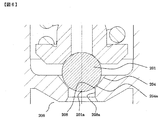
- FIG. 5 is a view for explaining the configuration of the relief valve mechanism of this embodiment.
- FIG. 7 shows an enlarged cross-sectional view of the relief valve mechanism of FIG.
- the sheet surface front end portion 208 is arranged at a position away from the sheet portion 204a.
- the seat surface front end portion 208 is disposed on the high pressure side relative to the high pressure side end portion 201 a of the relief valve body 201. That is, the intersection of the relief passage 208 and the relief sheet surface 204 is located on the discharge passage 12 side with respect to the end of the relief valve body on the discharge passage 12 side.
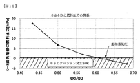
- the ratio obtained by ⁇ d / ⁇ D is obtained. It may be set to 0.6 or less. That is, the diameter ⁇ d of the relief passage 208 is formed to be 0.6 times or less than the sheet diameter ⁇ D of the relief sheet surface.
- FIG. 12 shows the relationship between ⁇ d / ⁇ D obtained by the fluid analysis simulation and the fuel pressure at the front end of the seat surface.
- the vertical axis represents the fuel pressure at the front end of the seat surface
- the horizontal axis represents the ratio ⁇ d / ⁇ D.
- Cavitation occurs when the fuel pressure at the front end of the seat surface is equal to or lower than the saturated vapor pressure shown in the figure. Therefore, the occurrence of cavitation can be suppressed by setting the ratio of ⁇ d / ⁇ D to 0.6 or less. . Or you may make it form so that the diameter of the relief channel
- FIG. Thereby, similarly to the above, the flow rate of fuel is small, the occurrence of fluid separation can be suppressed, and the generation of cavitation bubbles 210 can be suppressed.
- the relief sheet surface 204 is polished on the side of the pressurizing chamber 11 or the low pressure passage (suction passage 10c) from the intersection (sheet surface front end 208) of the relief passage 208 and the relief sheet surface 204. If the surface roughness of the sheet surface is poor, it is the same as the infinite number of edges formed on the sheet surface itself, and therefore fluid separation tends to occur. In this embodiment, the sheet surface is polished to suppress the occurrence of fluid separation on the sheet surface. In this embodiment, as shown in FIG. 5, the R portion is not formed at the intersection of the relief passage 208 and the relief sheet surface 204 (sheet surface front end portion 208), but these are intersected at a predetermined angle. ing.
- the formation of the R portion is high in manufacturing cost, and it is difficult to maintain the accuracy of the R portion in manufacturing. .
- the relief passage 208 is formed substantially in parallel with the expansion and contraction direction of the spring portion 203 that biases the relief valve body 201.
- the angle 204b between the relief passage 208a and the relief sheet surface 204 is formed so as to be inclined to 50 degrees or less. That is, the relief sheet surface 204 is formed so as to be inclined to the outer peripheral side by 50 degrees or less with respect to the relief passage 208.
- the seat surface front end portion 208 can be installed on the higher pressure side than the high pressure side end portion 201 a of the relief valve body 201.
- the intersection of the seat surface and the passage hole is installed at a position away from the seat portion, which is the smallest portion of the fuel passage area.
- the relief valve body 201 has a spherical shape.
- the relief valve body 201 does not necessarily have to be a spherical body, for example, a conical shape, a shape obtained by cutting the tip of the conical shape, or a portion that contacts the seat portion 204a. Only spherical may be sufficient.
- it is desirable that the sheet portion 204 a is disposed at a substantially central portion on the sheet surface 204. As a result, it is possible to obtain the operations and effects described above with reference to FIG.
- FIG. 9 shows a second embodiment of the present invention.
- a housing 205 surrounding the low-pressure chamber 207 existing downstream with respect to the relief valve body 201 and the seat portion 204 are integrated into a unit.
- a hole 214 is dug in the main body 211.
- the housing 205 and the seat portion 204a having an integral structure are formed as separate parts from the main body 211, and the housing 205 and the seat portion 204a having the integral structure are formed in a hole 214 dug into the main body 211. Is installed. If the relief valve mechanism of this configuration has the characteristics described in the first embodiment and the seat surface front end portion 208 is formed at a position away from the seat portion 204a, the effect described in the first embodiment is obtained.
- FIG. 10 shows a third embodiment of the present invention.
- a sheet member 215 is formed as a separate part from the main body 211, and the seat portion 204 a has a structure surrounding the high pressure chamber 206 on the upstream side, and is installed in a hole 214 dug into the main body 211. It is the composition which becomes. If the relief valve mechanism of this configuration has the characteristics described in the first embodiment and the seat surface front end portion 208 is formed at a position away from the seat portion 204a, the effect described in the first embodiment is obtained.
- FIG. 11 shows a fourth embodiment of the present invention.
- the main body body 211 is directly dug to form a relief sheet surface 204.
- the relief valve mechanism of this configuration has the characteristics described in the first embodiment and the seat surface front end portion 208 is formed at a position away from the seat portion 204a, the same effect as described in the first embodiment is obtained.
- Low pressure chamber 208 ... Seat surface tip, 208a ... Relief passage, 209 ... High speed vibration, 210 ... Cavitation bubbles, 211 ... body, 213 ... sheet portion, 214 ... hole, 215 ... sheet member.
Landscapes
- Engineering & Computer Science (AREA)
- General Engineering & Computer Science (AREA)
- Mechanical Engineering (AREA)
- Chemical & Material Sciences (AREA)
- Combustion & Propulsion (AREA)
- Fuel-Injection Apparatus (AREA)
Abstract
La présente invention vise à supprimer la cavitation qui se produit dans une partie de pointe de surface de siège quand un corps de vanne et une partie de siège rentrent en collision. A cet effet, l'invention concerne une vanne de refoulement d'une pompe à carburant, dans laquelle vanne le point d'intersection entre la surface de siège et un trou de canal d'écoulement est formé dans une position plus éloignée de la partie de siège comprenant la surface de siège et le corps de vanne quand la vanne est fermée, afin d'éliminer l'apparition de bulles de cavitation quand le corps de vanne est changé de façon à permettre une sortie de carburant à haute pression.
Priority Applications (4)
| Application Number | Priority Date | Filing Date | Title |
|---|---|---|---|
| JP2017517840A JP6507235B2 (ja) | 2015-05-12 | 2016-04-15 | 高圧燃料ポンプ |
| EP16792480.2A EP3296558B1 (fr) | 2015-05-12 | 2016-04-15 | Pompe à carburant à haute pression |
| CN201680026869.0A CN107532555B (zh) | 2015-05-12 | 2016-04-15 | 高压燃料泵 |
| US15/566,060 US10253741B2 (en) | 2015-05-12 | 2016-04-15 | High-pressure fuel pump |
Applications Claiming Priority (2)
| Application Number | Priority Date | Filing Date | Title |
|---|---|---|---|
| JP2015096996 | 2015-05-12 | ||
| JP2015-096996 | 2015-05-12 |
Publications (1)
| Publication Number | Publication Date |
|---|---|
| WO2016181755A1 true WO2016181755A1 (fr) | 2016-11-17 |
Family
ID=57248723
Family Applications (1)
| Application Number | Title | Priority Date | Filing Date |
|---|---|---|---|
| PCT/JP2016/062050 Ceased WO2016181755A1 (fr) | 2015-05-12 | 2016-04-15 | Pompe à carburant à haute pression |
Country Status (5)
| Country | Link |
|---|---|
| US (1) | US10253741B2 (fr) |
| EP (1) | EP3296558B1 (fr) |
| JP (1) | JP6507235B2 (fr) |
| CN (1) | CN107532555B (fr) |
| WO (1) | WO2016181755A1 (fr) |
Cited By (5)
| Publication number | Priority date | Publication date | Assignee | Title |
|---|---|---|---|---|
| WO2019097990A1 (fr) * | 2017-11-15 | 2019-05-23 | 日立オートモティブシステムズ株式会社 | Mécanisme de soupape de détente et pompe d'alimentation en carburant le comprenant |
| WO2019166136A1 (fr) * | 2018-02-27 | 2019-09-06 | Robert Bosch Gmbh | Soupape de limitation de pression |
| JP2019190426A (ja) * | 2018-04-27 | 2019-10-31 | 日立オートモティブシステムズ株式会社 | 燃料供給ポンプ及び燃料供給ポンプの製造方法 |
| US20220252030A1 (en) * | 2019-07-19 | 2022-08-11 | Robert Bosch Gmbh | High-Pressure Fuel Pump |
| WO2023032253A1 (fr) * | 2021-09-03 | 2023-03-09 | 日立Astemo株式会社 | Pompe à carburant |
Families Citing this family (1)
| Publication number | Priority date | Publication date | Assignee | Title |
|---|---|---|---|---|
| GB2620930B (en) * | 2022-07-25 | 2024-12-25 | Phinia Delphi Luxembourg Sarl | Pump |
Citations (8)
| Publication number | Priority date | Publication date | Assignee | Title |
|---|---|---|---|---|
| JPS55157163U (fr) * | 1979-04-27 | 1980-11-12 | ||
| JP2005214303A (ja) * | 2004-01-29 | 2005-08-11 | Aisin Seiki Co Ltd | リリーフバルブ |
| JP2007056989A (ja) * | 2005-08-24 | 2007-03-08 | Denso Corp | 流体制御弁およびその製造方法 |
| JP2007533882A (ja) * | 2003-11-25 | 2007-11-22 | ローベルト ボツシユ ゲゼルシヤフト ミツト ベシユレンクテル ハフツング | 特に内燃機関用の燃料噴射装置の高圧ポンプのための弁 |
| JP2011132941A (ja) * | 2009-11-26 | 2011-07-07 | Nippon Soken Inc | 圧力制御弁 |
| JP2011220195A (ja) * | 2010-04-08 | 2011-11-04 | Nippon Soken Inc | 圧力保持弁の検査装置および検査方法 |
| JP2013241835A (ja) * | 2012-05-17 | 2013-12-05 | Nippon Soken Inc | 高圧燃料ポンプのリリーフ弁 |
| JP2014043820A (ja) * | 2012-08-28 | 2014-03-13 | Denso Corp | 高圧燃料制御装置 |
Family Cites Families (19)
| Publication number | Priority date | Publication date | Assignee | Title |
|---|---|---|---|---|
| JP2000145591A (ja) * | 1998-09-01 | 2000-05-26 | Mitsubishi Electric Corp | 燃料供給装置 |
| JP2001173816A (ja) | 1999-12-17 | 2001-06-29 | Denso Corp | 逆止弁及びそれを用いた燃料噴射ポンプ |
| DE10231135A1 (de) * | 2002-07-10 | 2004-01-29 | Robert Bosch Gmbh | Druckentlastungsventil |
| EP1411238B1 (fr) | 2002-10-15 | 2006-01-11 | Robert Bosch Gmbh | Soupape de limitation de pression pour un système d'injection de carburant |
| JP2006242019A (ja) | 2005-03-01 | 2006-09-14 | Jtekt Corp | 燃料ポンプ用チェック弁 |
| JP5103138B2 (ja) * | 2007-11-01 | 2012-12-19 | 日立オートモティブシステムズ株式会社 | 高圧液体供給ポンプ |
| JP4595996B2 (ja) * | 2007-11-16 | 2010-12-08 | トヨタ自動車株式会社 | 内燃機関の高圧燃料供給装置 |
| JP5180365B2 (ja) * | 2009-02-20 | 2013-04-10 | 日立オートモティブシステムズ株式会社 | 高圧燃料供給ポンプ及びそれに用いる吐出弁ユニット |
| CN101865062A (zh) * | 2010-06-03 | 2010-10-20 | 宁波舜田良源油嘴油泵有限公司 | 等压出油阀 |
| JP5198511B2 (ja) * | 2010-06-29 | 2013-05-15 | 株式会社デンソー | 定残圧弁 |
| JP5616246B2 (ja) | 2011-01-28 | 2014-10-29 | 株式会社デンソー | 高圧ポンプ |
| JP5501272B2 (ja) * | 2011-03-08 | 2014-05-21 | 日立オートモティブシステムズ株式会社 | 高圧燃料供給ポンプ |
| WO2013117200A1 (fr) * | 2012-02-07 | 2013-08-15 | Volvo Lastvagnar Ab | Système d'injection de carburant |
| WO2014066696A1 (fr) * | 2012-10-25 | 2014-05-01 | Picospray, Llc | Système d'injection de carburant |
| JP2014105668A (ja) | 2012-11-29 | 2014-06-09 | Hitachi Automotive Systems Ltd | 高圧燃料供給ポンプ |
| JP2014105669A (ja) | 2012-11-29 | 2014-06-09 | Hitachi Automotive Systems Ltd | 高圧燃料供給ポンプ |
| JP6307307B2 (ja) | 2014-03-05 | 2018-04-04 | 日立オートモティブシステムズ株式会社 | 燃料ポンプ |
| WO2015164256A1 (fr) * | 2014-04-21 | 2015-10-29 | Stanadyne Llc | Soupape de surpression pour pompe à carburant à piston-plongeur unique |
| CN204187067U (zh) * | 2014-10-16 | 2015-03-04 | 宁波舜田良源油嘴油泵有限公司 | 一种高压共轨系统的限压阀 |
-
2016
- 2016-04-15 CN CN201680026869.0A patent/CN107532555B/zh active Active
- 2016-04-15 US US15/566,060 patent/US10253741B2/en active Active
- 2016-04-15 WO PCT/JP2016/062050 patent/WO2016181755A1/fr not_active Ceased
- 2016-04-15 JP JP2017517840A patent/JP6507235B2/ja active Active
- 2016-04-15 EP EP16792480.2A patent/EP3296558B1/fr active Active
Patent Citations (8)
| Publication number | Priority date | Publication date | Assignee | Title |
|---|---|---|---|---|
| JPS55157163U (fr) * | 1979-04-27 | 1980-11-12 | ||
| JP2007533882A (ja) * | 2003-11-25 | 2007-11-22 | ローベルト ボツシユ ゲゼルシヤフト ミツト ベシユレンクテル ハフツング | 特に内燃機関用の燃料噴射装置の高圧ポンプのための弁 |
| JP2005214303A (ja) * | 2004-01-29 | 2005-08-11 | Aisin Seiki Co Ltd | リリーフバルブ |
| JP2007056989A (ja) * | 2005-08-24 | 2007-03-08 | Denso Corp | 流体制御弁およびその製造方法 |
| JP2011132941A (ja) * | 2009-11-26 | 2011-07-07 | Nippon Soken Inc | 圧力制御弁 |
| JP2011220195A (ja) * | 2010-04-08 | 2011-11-04 | Nippon Soken Inc | 圧力保持弁の検査装置および検査方法 |
| JP2013241835A (ja) * | 2012-05-17 | 2013-12-05 | Nippon Soken Inc | 高圧燃料ポンプのリリーフ弁 |
| JP2014043820A (ja) * | 2012-08-28 | 2014-03-13 | Denso Corp | 高圧燃料制御装置 |
Cited By (10)
| Publication number | Priority date | Publication date | Assignee | Title |
|---|---|---|---|---|
| WO2019097990A1 (fr) * | 2017-11-15 | 2019-05-23 | 日立オートモティブシステムズ株式会社 | Mécanisme de soupape de détente et pompe d'alimentation en carburant le comprenant |
| JP2019090366A (ja) * | 2017-11-15 | 2019-06-13 | 日立オートモティブシステムズ株式会社 | リリーフ弁機構およびこれを備えた燃料供給ポンプ |
| WO2019166136A1 (fr) * | 2018-02-27 | 2019-09-06 | Robert Bosch Gmbh | Soupape de limitation de pression |
| JP2019190426A (ja) * | 2018-04-27 | 2019-10-31 | 日立オートモティブシステムズ株式会社 | 燃料供給ポンプ及び燃料供給ポンプの製造方法 |
| JP7089399B2 (ja) | 2018-04-27 | 2022-06-22 | 日立Astemo株式会社 | 燃料供給ポンプ及び燃料供給ポンプの製造方法 |
| US20220252030A1 (en) * | 2019-07-19 | 2022-08-11 | Robert Bosch Gmbh | High-Pressure Fuel Pump |
| WO2023032253A1 (fr) * | 2021-09-03 | 2023-03-09 | 日立Astemo株式会社 | Pompe à carburant |
| JPWO2023032253A1 (fr) * | 2021-09-03 | 2023-03-09 | ||
| JP7518980B2 (ja) | 2021-09-03 | 2024-07-18 | 日立Astemo株式会社 | 燃料ポンプ |
| US12460612B2 (en) | 2021-09-03 | 2025-11-04 | Hitachi Astemo, Ltd. | Fuel pump |
Also Published As
| Publication number | Publication date |
|---|---|
| EP3296558A4 (fr) | 2018-12-19 |
| JP6507235B2 (ja) | 2019-04-24 |
| US20180128229A1 (en) | 2018-05-10 |
| CN107532555A (zh) | 2018-01-02 |
| JPWO2016181755A1 (ja) | 2017-12-07 |
| EP3296558A1 (fr) | 2018-03-21 |
| EP3296558B1 (fr) | 2020-12-23 |
| US10253741B2 (en) | 2019-04-09 |
| CN107532555B (zh) | 2020-11-06 |
Similar Documents
| Publication | Publication Date | Title |
|---|---|---|
| WO2016181755A1 (fr) | Pompe à carburant à haute pression | |
| US20200080526A1 (en) | High-pressure fuel supply pump provided with electromagnetic intake valve | |
| JP6697552B2 (ja) | 高圧燃料供給ポンプ | |
| JP6307307B2 (ja) | 燃料ポンプ | |
| JP2017002759A (ja) | 高圧燃料供給ポンプ | |
| JP2015536411A (ja) | 弁装置 | |
| JP6342020B2 (ja) | 弁機構及びこれを備えた高圧燃料供給ポンプ | |
| JP6670720B2 (ja) | 高圧燃料供給ポンプ | |
| JP4078320B2 (ja) | ポペット弁装置及びそれを備えた電子制御燃料噴射装置 | |
| KR102057140B1 (ko) | 연료 시스템 밸브 어셈블리 | |
| JP5708092B2 (ja) | インジェクタ | |
| CN116261626B (zh) | 燃料泵 | |
| WO2016088340A1 (fr) | Pompe haute pression | |
| JP6588161B2 (ja) | 高圧燃料供給ポンプ | |
| WO2016013301A1 (fr) | Pompe à carburant à haute pression | |
| EP2420667A1 (fr) | Injecteur de carburant avec volume d'amortisseur et procédé de contrôle de dépassement de pression | |
| CN109964032B (zh) | 用于燃料喷射系统的高压泵 | |
| JP6203115B2 (ja) | 燃料噴射ノズル | |
| CN112243474B (zh) | 电磁阀和高压燃料供给泵 | |
| JP5648539B2 (ja) | 燃料噴射装置 | |
| JP6689153B2 (ja) | 燃料供給ポンプ | |
| JP2009115256A (ja) | 逆止弁 | |
| JP6146365B2 (ja) | 燃料供給システム | |
| CN107667217A (zh) | 用于燃料喷射系统的阀装置以及燃料喷射系统 |
Legal Events
| Date | Code | Title | Description |
|---|---|---|---|
| 121 | Ep: the epo has been informed by wipo that ep was designated in this application |
Ref document number: 16792480 Country of ref document: EP Kind code of ref document: A1 |
|
| ENP | Entry into the national phase |
Ref document number: 2017517840 Country of ref document: JP Kind code of ref document: A |
|
| WWE | Wipo information: entry into national phase |
Ref document number: 15566060 Country of ref document: US |
|
| NENP | Non-entry into the national phase |
Ref country code: DE |