WO2016181809A1 - Module de fil électrique - Google Patents
Module de fil électrique Download PDFInfo
- Publication number
- WO2016181809A1 WO2016181809A1 PCT/JP2016/062891 JP2016062891W WO2016181809A1 WO 2016181809 A1 WO2016181809 A1 WO 2016181809A1 JP 2016062891 W JP2016062891 W JP 2016062891W WO 2016181809 A1 WO2016181809 A1 WO 2016181809A1
- Authority
- WO
- WIPO (PCT)
- Prior art keywords
- conductive
- electric wire
- connection
- electroconductive
- wire module
- Prior art date
- Legal status (The legal status is an assumption and is not a legal conclusion. Google has not performed a legal analysis and makes no representation as to the accuracy of the status listed.)
- Ceased
Links
Images



Classifications
-
- H—ELECTRICITY
- H01—ELECTRIC ELEMENTS
- H01R—ELECTRICALLY-CONDUCTIVE CONNECTIONS; STRUCTURAL ASSOCIATIONS OF A PLURALITY OF MUTUALLY-INSULATED ELECTRICAL CONNECTING ELEMENTS; COUPLING DEVICES; CURRENT COLLECTORS
- H01R4/00—Electrically-conductive connections between two or more conductive members in direct contact, i.e. touching one another; Means for effecting or maintaining such contact; Electrically-conductive connections having two or more spaced connecting locations for conductors and using contact members penetrating insulation
- H01R4/58—Electrically-conductive connections between two or more conductive members in direct contact, i.e. touching one another; Means for effecting or maintaining such contact; Electrically-conductive connections having two or more spaced connecting locations for conductors and using contact members penetrating insulation characterised by the form or material of the contacting members
- H01R4/60—Connections between or with tubular conductors
-
- H—ELECTRICITY
- H01—ELECTRIC ELEMENTS
- H01R—ELECTRICALLY-CONDUCTIVE CONNECTIONS; STRUCTURAL ASSOCIATIONS OF A PLURALITY OF MUTUALLY-INSULATED ELECTRICAL CONNECTING ELEMENTS; COUPLING DEVICES; CURRENT COLLECTORS
- H01R13/00—Details of coupling devices of the kinds covered by groups H01R12/70 or H01R24/00 - H01R33/00
- H01R13/56—Means for preventing chafing or fracture of flexible leads at outlet from coupling part
- H01R13/562—Bending-relieving
-
- H—ELECTRICITY
- H01—ELECTRIC ELEMENTS
- H01R—ELECTRICALLY-CONDUCTIVE CONNECTIONS; STRUCTURAL ASSOCIATIONS OF A PLURALITY OF MUTUALLY-INSULATED ELECTRICAL CONNECTING ELEMENTS; COUPLING DEVICES; CURRENT COLLECTORS
- H01R4/00—Electrically-conductive connections between two or more conductive members in direct contact, i.e. touching one another; Means for effecting or maintaining such contact; Electrically-conductive connections having two or more spaced connecting locations for conductors and using contact members penetrating insulation
- H01R4/70—Insulation of connections
- H01R4/72—Insulation of connections using a heat shrinking insulating sleeve
-
- H—ELECTRICITY
- H01—ELECTRIC ELEMENTS
- H01R—ELECTRICALLY-CONDUCTIVE CONNECTIONS; STRUCTURAL ASSOCIATIONS OF A PLURALITY OF MUTUALLY-INSULATED ELECTRICAL CONNECTING ELEMENTS; COUPLING DEVICES; CURRENT COLLECTORS
- H01R11/00—Individual connecting elements providing two or more spaced connecting locations for conductive members which are, or may be, thereby interconnected, e.g. end pieces for wires or cables supported by the wire or cable and having means for facilitating electrical connection to some other wire, terminal, or conductive member, blocks of binding posts
- H01R11/11—End pieces or tapping pieces for wires, supported by the wire and for facilitating electrical connection to some other wire, terminal or conductive member
- H01R11/12—End pieces terminating in an eye, hook, or fork
-
- H—ELECTRICITY
- H01—ELECTRIC ELEMENTS
- H01R—ELECTRICALLY-CONDUCTIVE CONNECTIONS; STRUCTURAL ASSOCIATIONS OF A PLURALITY OF MUTUALLY-INSULATED ELECTRICAL CONNECTING ELEMENTS; COUPLING DEVICES; CURRENT COLLECTORS
- H01R4/00—Electrically-conductive connections between two or more conductive members in direct contact, i.e. touching one another; Means for effecting or maintaining such contact; Electrically-conductive connections having two or more spaced connecting locations for conductors and using contact members penetrating insulation
- H01R4/02—Soldered or welded connections
- H01R4/021—Soldered or welded connections between two or more cables or wires
-
- H—ELECTRICITY
- H01—ELECTRIC ELEMENTS
- H01R—ELECTRICALLY-CONDUCTIVE CONNECTIONS; STRUCTURAL ASSOCIATIONS OF A PLURALITY OF MUTUALLY-INSULATED ELECTRICAL CONNECTING ELEMENTS; COUPLING DEVICES; CURRENT COLLECTORS
- H01R4/00—Electrically-conductive connections between two or more conductive members in direct contact, i.e. touching one another; Means for effecting or maintaining such contact; Electrically-conductive connections having two or more spaced connecting locations for conductors and using contact members penetrating insulation
- H01R4/02—Soldered or welded connections
- H01R4/029—Welded connections
-
- H—ELECTRICITY
- H01—ELECTRIC ELEMENTS
- H01R—ELECTRICALLY-CONDUCTIVE CONNECTIONS; STRUCTURAL ASSOCIATIONS OF A PLURALITY OF MUTUALLY-INSULATED ELECTRICAL CONNECTING ELEMENTS; COUPLING DEVICES; CURRENT COLLECTORS
- H01R4/00—Electrically-conductive connections between two or more conductive members in direct contact, i.e. touching one another; Means for effecting or maintaining such contact; Electrically-conductive connections having two or more spaced connecting locations for conductors and using contact members penetrating insulation
- H01R4/10—Electrically-conductive connections between two or more conductive members in direct contact, i.e. touching one another; Means for effecting or maintaining such contact; Electrically-conductive connections having two or more spaced connecting locations for conductors and using contact members penetrating insulation effected solely by twisting, wrapping, bending, crimping, or other permanent deformation
- H01R4/18—Electrically-conductive connections between two or more conductive members in direct contact, i.e. touching one another; Means for effecting or maintaining such contact; Electrically-conductive connections having two or more spaced connecting locations for conductors and using contact members penetrating insulation effected solely by twisting, wrapping, bending, crimping, or other permanent deformation by crimping
- H01R4/183—Electrically-conductive connections between two or more conductive members in direct contact, i.e. touching one another; Means for effecting or maintaining such contact; Electrically-conductive connections having two or more spaced connecting locations for conductors and using contact members penetrating insulation effected solely by twisting, wrapping, bending, crimping, or other permanent deformation by crimping for cylindrical elongated bodies, e.g. cables having circular cross-section
Definitions
- an electric wire module that connects two devices may include a relatively hard single-core wire and a relatively flexible stranded wire.
- the shape of the single core wire is relatively maintained, and the portion of the stranded wire is bent relatively flexibly.
- connection portion includes a rod-shaped first connection portion including a portion connected to the other side end portion in a state where the outer peripheral surface is covered by the other side end portion of the second conductive portion; And a second connection part formed in a terminal shape on the opposite side to the second conductive part side of the connection part.
- the second conductive portion and the connection portion can be connected by the same operation as the connection between the first conductive portion and the second conductive portion.
- the shield body 5 may be a metal pipe in which a metal such as aluminum or copper is formed in a cylindrical shape, or a braided wire in which a plurality of strands are knitted in a cylindrical shape.
- the first conductive portion 1 may be disposed on a curved path, or may be disposed on a linear path, or may be disposed on a path including both a curved path and a linear path. Conceivable. For example, when the 1st electroconductive part 1 is arrange
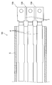
- the second conductive portion 2 is formed in a cylindrical shape that is more flexible than the first conductive portion 1.
- the second conductive portion 2 is formed flexibly so that it can expand and contract and bend due to vibration of the vehicle.
- the second conductive portion 2 is a braided wire in which a plurality of strands are knitted into a cylindrical shape.
- the one end portion 21 of the second conductive portion 2 is connected to the first conductive portion 1 so as to cover the outer peripheral surface of the end portion of the first conductive portion 1.
- a connecting portion 3 described later is connected to the other end portion 22 of the second conductive portion 2.
- the intermediate portion 33 is a portion excluding both end portions of another single core wire, and is a portion connecting the first connection portion 31 and the second connection portion 32.
- the intermediate portion 33 is a portion other than the end portion of the portion in which another single core wire having a round bar shape is maintained in its shape. Therefore, the intermediate portion 33 is a portion that can be maintained in a shape having rigidity capable of maintaining the shape along the routing route. For this reason, in the cross section cut
- the case where the cross-sectional shape of the intermediate portion 33 is a shape other than a round shape such as a rounded square shape is also conceivable.
- the case where the insulated wire provided with the insulation coating formed by extrusion molding around the single core wire as the 1st electroconductive part 1 and the connection part 3 is also considered.
- the insulating coating portion 4 includes an insulating coating formed by extrusion molding around the first conductive portion 1 and the connection portion 3.
- the insulating coating around the end portion of the first conductive portion 1 and the first connection portion 31 of the connection portion 3 is removed and the second conductive portion 2 is connected.
- the second conductive portion 2 is a braided wire in which a plurality of strands are knitted into a cylindrical shape.
- the tubular braided wire is more flexible and can absorb more vibration.
Landscapes
- Details Of Indoor Wiring (AREA)
- Connections Effected By Soldering, Adhesion, Or Permanent Deformation (AREA)
Abstract
La présente invention permet, lors de la connexion d'un élément électroconducteur souple à un fil à âme unique, de connecter plus facilement entre eux l'élément électroconducteur flexible et le fil à âme unique sans qu'il soit nécessaire de mettre en oeuvre un processus d'aplatissement du fil à âme unique pour former une partie de connexion avec l'élément électroconducteur souple. Le module de fil électrique comporte : une première partie électroconductrice (1) qui constitue un fil à âme unique ; une seconde partie électroconductrice (2), formée en tant que cylindre et qui est plus souple que la première partie électroconductrice (1), la seconde partie électroconductrice (2) étant connectée à une partie d'extrémité (21) de manière à couvrir la surface périphérique extérieure d'une partie d'extrémité de la première partie électroconductrice (1) ; une partie de connexion (3) électroconductrice connectée à l'autre partie d'extrémité (22) de la seconde partie électroconductrice (2), la partie de connexion (3) comprenant une partie en forme de borne qui peut être connectée à un élément correspondant ; et une partie revêtement (4) isolant couvrant au minimum la région circonvoisine de la première partie électroconductrice (1) et de la seconde partie électroconductrice (2).
Priority Applications (2)
| Application Number | Priority Date | Filing Date | Title |
|---|---|---|---|
| CN201680026617.8A CN107534228B (zh) | 2015-05-14 | 2016-04-25 | 电线模块 |
| US15/573,530 US10326218B2 (en) | 2015-05-14 | 2016-04-25 | Electric wire module |
Applications Claiming Priority (2)
| Application Number | Priority Date | Filing Date | Title |
|---|---|---|---|
| JP2015-098766 | 2015-05-14 | ||
| JP2015098766A JP6409672B2 (ja) | 2015-05-14 | 2015-05-14 | 電線モジュール |
Publications (1)
| Publication Number | Publication Date |
|---|---|
| WO2016181809A1 true WO2016181809A1 (fr) | 2016-11-17 |
Family
ID=57249202
Family Applications (1)
| Application Number | Title | Priority Date | Filing Date |
|---|---|---|---|
| PCT/JP2016/062891 Ceased WO2016181809A1 (fr) | 2015-05-14 | 2016-04-25 | Module de fil électrique |
Country Status (4)
| Country | Link |
|---|---|
| US (1) | US10326218B2 (fr) |
| JP (1) | JP6409672B2 (fr) |
| CN (1) | CN107534228B (fr) |
| WO (1) | WO2016181809A1 (fr) |
Families Citing this family (3)
| Publication number | Priority date | Publication date | Assignee | Title |
|---|---|---|---|---|
| JP6394524B2 (ja) * | 2015-07-10 | 2018-09-26 | 株式会社オートネットワーク技術研究所 | 電磁シールド部材及び電磁シールド部材付配線装置 |
| JP7087348B2 (ja) * | 2017-11-08 | 2022-06-21 | 株式会社オートネットワーク技術研究所 | バスバーモジュール及びバスバー |
| DE102020106415B4 (de) * | 2020-03-10 | 2021-09-30 | Lisa Dräxlmaier GmbH | REIBSCHWEIßVERBINDER UND VERFAHREN ZU DESSEN HERSTELLUNG |
Citations (3)
| Publication number | Priority date | Publication date | Assignee | Title |
|---|---|---|---|---|
| JPH08203585A (ja) * | 1995-01-27 | 1996-08-09 | Fujikura Ltd | バッテリ間接続具 |
| JP2002136019A (ja) * | 2000-10-18 | 2002-05-10 | Mitsubishi Electric Corp | 車両用交流発電機およびその固定子巻線に適用される導体線の接続係止部形成方法 |
| JP2009199892A (ja) * | 2008-02-21 | 2009-09-03 | Sumitomo Electric Fine Polymer Inc | 熱収縮チューブ付き圧着端子、該圧着端子の製造用治具および製造方法 |
Family Cites Families (37)
| Publication number | Priority date | Publication date | Assignee | Title |
|---|---|---|---|---|
| US1751405A (en) * | 1926-03-10 | 1930-03-18 | Nat Carbon Co Inc | Terminal and method of making same |
| US2286097A (en) * | 1938-10-29 | 1942-06-09 | Westinghouse Electric & Mfg Co | Terminal |
| JPS63143862U (fr) | 1987-03-12 | 1988-09-21 | ||
| EP0498897B1 (fr) * | 1990-09-03 | 1995-11-29 | The Furukawa Electric Co., Ltd. | Materiau pour cablage electrique et transformateur |
| US5541380A (en) * | 1994-09-16 | 1996-07-30 | Methode Electronics, Inc. | Braided cable solidification |
| FR2751141B1 (fr) * | 1996-07-10 | 1998-10-30 | Eurocopter France | Perfectionnements aux conducteurs de metallisation, pour la realisation de liaisons assurant une continuite electrique entre pieces mecanique |
| JP2000068007A (ja) * | 1998-08-20 | 2000-03-03 | Fujitsu Takamisawa Component Ltd | ケーブル付き平衡伝送用コネクタ |
| JP2002324627A (ja) * | 2001-04-25 | 2002-11-08 | Yazaki Corp | 電磁波シールド構造 |
| JP3946096B2 (ja) * | 2001-09-11 | 2007-07-18 | 株式会社オートネットワーク技術研究所 | シールドコネクタ |
| JP3786594B2 (ja) * | 2001-10-01 | 2006-06-14 | 矢崎総業株式会社 | 電磁波シールド編組 |
| JP3713528B2 (ja) * | 2001-12-26 | 2005-11-09 | 株式会社オートネットワーク技術研究所 | 機器取付け用ワイヤーハーネス |
| US20030236016A1 (en) * | 2002-06-20 | 2003-12-25 | The Furukawa Electric Co., Ltd. | Tubular bus bar, insulating coating method therefor, and insulating coating structure therefor |
| JP4524238B2 (ja) * | 2005-09-29 | 2010-08-11 | 矢崎総業株式会社 | 接地部材及び電線接続ユニット |
| JP5107256B2 (ja) * | 2006-11-24 | 2012-12-26 | 株式会社オートネットワーク技術研究所 | シールド導電体 |
| JP4932659B2 (ja) * | 2007-10-03 | 2012-05-16 | 矢崎総業株式会社 | シールドコネクタおよびシールドコネクタの製造方法 |
| JP5176533B2 (ja) * | 2007-12-19 | 2013-04-03 | 住友電装株式会社 | 電線の止水方法及び該止水方法で形成された止水部を有する電線 |
| JP5243020B2 (ja) * | 2007-12-28 | 2013-07-24 | スリーエム イノベイティブ プロパティズ カンパニー | 電線被覆用チューブ |
| FR2929049B1 (fr) * | 2008-03-19 | 2010-03-12 | Labinal | Procede de reprise du blindage electromagnetique individuel de cables electriques d'un toron sur un connecteur electrique. |
| JP2009230997A (ja) * | 2008-03-21 | 2009-10-08 | Autonetworks Technologies Ltd | 端子金具付き電線の製造方法及び端子金具付き電線 |
| JP5483273B2 (ja) * | 2008-12-12 | 2014-05-07 | 矢崎総業株式会社 | オス端子への電線接続構造 |
| JP2012009229A (ja) * | 2010-06-23 | 2012-01-12 | Jst Mfg Co Ltd | 同軸ケーブル用コンタクト及び端末処理方法 |
| WO2012018049A1 (fr) * | 2010-08-06 | 2012-02-09 | 株式会社オートネットワーク技術研究所 | Fil électrique muni d'une cosse et d'un connecteur |
| JP5824210B2 (ja) * | 2010-12-16 | 2015-11-25 | 矢崎総業株式会社 | ワイヤハーネスの防液構造 |
| DE102011017070B4 (de) * | 2011-04-14 | 2013-10-31 | Auto-Kabel Management Gmbh | Herstellung eines elektrischen Kabels sowie Verfahren zur Herstellung einer Verbindung |
| JP5800590B2 (ja) * | 2011-06-17 | 2015-10-28 | 矢崎総業株式会社 | 電線接続端子および当該電線接続端子を備えたワイヤハーネス |
| JP5890119B2 (ja) * | 2011-07-20 | 2016-03-22 | 矢崎総業株式会社 | 低背化コネクタとその製造方法 |
| JP5741502B2 (ja) * | 2011-07-26 | 2015-07-01 | 株式会社オートネットワーク技術研究所 | 端子付き電線およびその製造方法 |
| JP6080350B2 (ja) * | 2011-10-31 | 2017-02-15 | 矢崎総業株式会社 | ワイヤハーネス |
| JP2013099184A (ja) * | 2011-11-04 | 2013-05-20 | Yazaki Corp | ワイヤハーネス |
| JP6002985B2 (ja) * | 2011-12-27 | 2016-10-05 | 矢崎総業株式会社 | ワイヤハーネス用中間部材及びワイヤハーネス |
| JP2013246886A (ja) * | 2012-05-23 | 2013-12-09 | Auto Network Gijutsu Kenkyusho:Kk | 端子付き電線およびその製造方法、ならびに治具 |
| JP5772742B2 (ja) * | 2012-07-04 | 2015-09-02 | 日立金属株式会社 | 電線保持装置及びワイヤハーネス |
| JP2014017181A (ja) * | 2012-07-11 | 2014-01-30 | Tyco Electronics Japan Kk | シールドケーブルハーネスの端末構造およびその製造方法 |
| JP6069727B2 (ja) * | 2012-09-26 | 2017-02-01 | 矢崎総業株式会社 | ワイヤハーネスの製造方法 |
| JP6062874B2 (ja) * | 2014-02-13 | 2017-01-18 | トヨタ自動車株式会社 | 端子台 |
| US9356438B2 (en) * | 2014-02-27 | 2016-05-31 | Delphi Technologies, Inc. | Wire cable assembly having a terminal with an encapsulated wire end |
| JP6352872B2 (ja) * | 2015-01-07 | 2018-07-04 | トヨタ自動車株式会社 | シールド電線接続構造 |
-
2015
- 2015-05-14 JP JP2015098766A patent/JP6409672B2/ja active Active
-
2016
- 2016-04-25 CN CN201680026617.8A patent/CN107534228B/zh active Active
- 2016-04-25 WO PCT/JP2016/062891 patent/WO2016181809A1/fr not_active Ceased
- 2016-04-25 US US15/573,530 patent/US10326218B2/en active Active
Patent Citations (3)
| Publication number | Priority date | Publication date | Assignee | Title |
|---|---|---|---|---|
| JPH08203585A (ja) * | 1995-01-27 | 1996-08-09 | Fujikura Ltd | バッテリ間接続具 |
| JP2002136019A (ja) * | 2000-10-18 | 2002-05-10 | Mitsubishi Electric Corp | 車両用交流発電機およびその固定子巻線に適用される導体線の接続係止部形成方法 |
| JP2009199892A (ja) * | 2008-02-21 | 2009-09-03 | Sumitomo Electric Fine Polymer Inc | 熱収縮チューブ付き圧着端子、該圧着端子の製造用治具および製造方法 |
Also Published As
| Publication number | Publication date |
|---|---|
| JP6409672B2 (ja) | 2018-10-24 |
| CN107534228B (zh) | 2019-09-27 |
| US10326218B2 (en) | 2019-06-18 |
| JP2016219096A (ja) | 2016-12-22 |
| US20180123265A1 (en) | 2018-05-03 |
| CN107534228A (zh) | 2018-01-02 |
Similar Documents
| Publication | Publication Date | Title |
|---|---|---|
| JP5935787B2 (ja) | ワイヤハーネス及びワイヤハーネス製造方法 | |
| CN107710900B (zh) | 屏蔽结构以及屏蔽用编织部件 | |
| CN103958278B (zh) | 高压导电线及线束 | |
| JP6673404B2 (ja) | 導電部材 | |
| US20190337472A1 (en) | Wire harness | |
| EP2849971B1 (fr) | Structure de connexion par sertissage pour une tresse cylindrique | |
| JPWO2015002180A1 (ja) | 導電線、導電線の製造方法及び導電線の配索構造 | |
| JP6270089B2 (ja) | 導電部材 | |
| JP6471909B2 (ja) | ワイヤハーネス | |
| WO2014050754A1 (fr) | Procédé de production d'un faisceau électrique | |
| JP2016054030A (ja) | ワイヤハーネスおよびシールド導電路 | |
| JP2015201284A (ja) | ワイヤハーネス | |
| JPWO2018190096A1 (ja) | ワイヤハーネス | |
| JP2016032388A (ja) | ワイヤハーネス | |
| US20190172608A1 (en) | Conductive wire and covered conductive wire | |
| JP6409672B2 (ja) | 電線モジュール | |
| JP2016136460A (ja) | ワイヤハーネス | |
| JP2020004543A (ja) | ワイヤハーネス | |
| US10630003B2 (en) | Conductor connecting structure and wire harness | |
| JP2016046929A (ja) | ワイヤハーネス用の外装部材、及びワイヤハーネス | |
| JP4820573B2 (ja) | シールド導電路 | |
| WO2016158400A1 (fr) | Module de câble électrique et procédé de fabrication d'un module de câble électrique | |
| JP2019029083A (ja) | 導電路 | |
| JP2017010691A (ja) | 接続構造、及び、ワイヤハーネス | |
| JP2023141870A (ja) | ワイヤハーネス |
Legal Events
| Date | Code | Title | Description |
|---|---|---|---|
| 121 | Ep: the epo has been informed by wipo that ep was designated in this application |
Ref document number: 16792534 Country of ref document: EP Kind code of ref document: A1 |
|
| WWE | Wipo information: entry into national phase |
Ref document number: 15573530 Country of ref document: US |
|
| NENP | Non-entry into the national phase |
Ref country code: DE |
|
| 122 | Ep: pct application non-entry in european phase |
Ref document number: 16792534 Country of ref document: EP Kind code of ref document: A1 |