WO2016185594A1 - 固体酸化物形燃料電池用セルモジュール及びそれを用いた固体酸化物形燃料電池 - Google Patents
固体酸化物形燃料電池用セルモジュール及びそれを用いた固体酸化物形燃料電池 Download PDFInfo
- Publication number
- WO2016185594A1 WO2016185594A1 PCT/JP2015/064553 JP2015064553W WO2016185594A1 WO 2016185594 A1 WO2016185594 A1 WO 2016185594A1 JP 2015064553 W JP2015064553 W JP 2015064553W WO 2016185594 A1 WO2016185594 A1 WO 2016185594A1
- Authority
- WO
- WIPO (PCT)
- Prior art keywords
- cell
- gas
- gas permeability
- cell substrate
- substrate
- Prior art date
- Legal status (The legal status is an assumption and is not a legal conclusion. Google has not performed a legal analysis and makes no representation as to the accuracy of the status listed.)
- Ceased
Links
Images


Classifications
-
- H—ELECTRICITY
- H01—ELECTRIC ELEMENTS
- H01M—PROCESSES OR MEANS, e.g. BATTERIES, FOR THE DIRECT CONVERSION OF CHEMICAL ENERGY INTO ELECTRICAL ENERGY
- H01M8/00—Fuel cells; Manufacture thereof
- H01M8/02—Details
- H01M8/0202—Collectors; Separators, e.g. bipolar separators; Interconnectors
-
- H—ELECTRICITY
- H01—ELECTRIC ELEMENTS
- H01M—PROCESSES OR MEANS, e.g. BATTERIES, FOR THE DIRECT CONVERSION OF CHEMICAL ENERGY INTO ELECTRICAL ENERGY
- H01M8/00—Fuel cells; Manufacture thereof
- H01M8/02—Details
- H01M8/0202—Collectors; Separators, e.g. bipolar separators; Interconnectors
- H01M8/0258—Collectors; Separators, e.g. bipolar separators; Interconnectors characterised by the configuration of channels, e.g. by the flow field of the reactant or coolant
-
- H—ELECTRICITY
- H01—ELECTRIC ELEMENTS
- H01M—PROCESSES OR MEANS, e.g. BATTERIES, FOR THE DIRECT CONVERSION OF CHEMICAL ENERGY INTO ELECTRICAL ENERGY
- H01M8/00—Fuel cells; Manufacture thereof
- H01M8/02—Details
-
- H—ELECTRICITY
- H01—ELECTRIC ELEMENTS
- H01M—PROCESSES OR MEANS, e.g. BATTERIES, FOR THE DIRECT CONVERSION OF CHEMICAL ENERGY INTO ELECTRICAL ENERGY
- H01M8/00—Fuel cells; Manufacture thereof
- H01M8/10—Fuel cells with solid electrolytes
- H01M8/12—Fuel cells with solid electrolytes operating at high temperature, e.g. with stabilised ZrO2 electrolyte
- H01M8/1213—Fuel cells with solid electrolytes operating at high temperature, e.g. with stabilised ZrO2 electrolyte characterised by the electrode/electrolyte combination or the supporting material
- H01M8/1226—Fuel cells with solid electrolytes operating at high temperature, e.g. with stabilised ZrO2 electrolyte characterised by the electrode/electrolyte combination or the supporting material characterised by the supporting layer
-
- H—ELECTRICITY
- H01—ELECTRIC ELEMENTS
- H01M—PROCESSES OR MEANS, e.g. BATTERIES, FOR THE DIRECT CONVERSION OF CHEMICAL ENERGY INTO ELECTRICAL ENERGY
- H01M8/00—Fuel cells; Manufacture thereof
- H01M8/10—Fuel cells with solid electrolytes
- H01M8/12—Fuel cells with solid electrolytes operating at high temperature, e.g. with stabilised ZrO2 electrolyte
- H01M2008/1293—Fuel cells with solid oxide electrolytes
-
- H—ELECTRICITY
- H01—ELECTRIC ELEMENTS
- H01M—PROCESSES OR MEANS, e.g. BATTERIES, FOR THE DIRECT CONVERSION OF CHEMICAL ENERGY INTO ELECTRICAL ENERGY
- H01M8/00—Fuel cells; Manufacture thereof
- H01M8/02—Details
- H01M8/0202—Collectors; Separators, e.g. bipolar separators; Interconnectors
- H01M8/023—Porous and characterised by the material
- H01M8/0232—Metals or alloys
-
- Y—GENERAL TAGGING OF NEW TECHNOLOGICAL DEVELOPMENTS; GENERAL TAGGING OF CROSS-SECTIONAL TECHNOLOGIES SPANNING OVER SEVERAL SECTIONS OF THE IPC; TECHNICAL SUBJECTS COVERED BY FORMER USPC CROSS-REFERENCE ART COLLECTIONS [XRACs] AND DIGESTS
- Y02—TECHNOLOGIES OR APPLICATIONS FOR MITIGATION OR ADAPTATION AGAINST CLIMATE CHANGE
- Y02E—REDUCTION OF GREENHOUSE GAS [GHG] EMISSIONS, RELATED TO ENERGY GENERATION, TRANSMISSION OR DISTRIBUTION
- Y02E60/00—Enabling technologies; Technologies with a potential or indirect contribution to GHG emissions mitigation
- Y02E60/30—Hydrogen technology
- Y02E60/50—Fuel cells
Definitions
- the present invention relates to a cell module for a solid oxide fuel cell and a solid oxide fuel cell using the same. Specifically, the present invention relates to a cell module for a solid oxide fuel cell that suppresses an excessive temperature rise and a solid oxide fuel cell using the same.
- SOFC solid oxide fuel cell
- the solid oxide fuel cell uses a solid oxide material having oxygen ion conductivity such as stabilized zirconia or ceria-based solid solution as an electrolyte. Further, the SOFC forms a single cell by laminating an air electrode and a fuel electrode each having gas permeability on both surfaces of a solid electrolyte. Then, using a gas-impermeable solid electrolyte as a partition wall, a fuel gas such as hydrogen or hydrocarbon is supplied from the outside to the fuel electrode side, and an oxidant gas such as air is supplied to the air electrode side to generate electricity. . In addition to hydrogen and hydrocarbons, a reformed gas obtained by reforming various liquid fuels may be used as the fuel gas.
- a reformed gas obtained by reforming various liquid fuels may be used as the fuel gas.
- Patent Document 1 includes a solid electrolyte layer, a first porous electrode layer, a second porous electrode layer, and a conductive porous support for supporting them, and a surface of the conductive porous support.
- circulates in the state which gas contacted is disclosed.
- the conductive porous support has portions with different porosities, and the portions with different porosities have a low porosity on the upstream side in the gas flow direction of the gas flow passage and a high porosity on the downstream side.
- the configuration is disclosed. As described above, the high porosity and high efficiency of the electrochemical cell are achieved by adopting a configuration in which the porosity is low on the upstream side of the gas flow passage and the porosity is increased on the downstream side.
- An object of the present invention is to provide a cell module for a solid oxide fuel cell that makes it difficult to exceed the operating limit temperature of a single cell and suppresses a decrease in durability, and a solid oxide fuel cell using the same. Is to provide.
- a cell module for a solid oxide fuel cell comprises a cell substrate having gas permeability, a fuel electrode formed on the cell substrate, a solid electrolyte, and an air electrode.
- a cell substrate having gas permeability
- a fuel electrode formed on the cell substrate
- a solid electrolyte formed on the cell substrate
- an air electrode a solid electrolyte
- the gas permeability at the center of the cell substrate is lower than the gas permeability at the inlet and outlet.
- the gas permeability at the outlet portion of the cell substrate is lower than the gas permeability at the portion other than the outlet portion.
- the cell module for a solid oxide fuel cell of the present invention By using the cell module for a solid oxide fuel cell of the present invention, the power generation amount of a single cell facing the portion where the gas permeability of the cell substrate is reduced is reduced. Therefore, it becomes possible to lower the maximum temperature of the cell module and suppress a decrease in durability of the cell module.
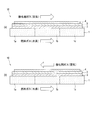
- FIG. 1 is a schematic sectional view showing a cell module for a solid oxide fuel cell.
- (A) shows the case where the fuel gas and the oxidant gas are in parallel flow, and (b) shows the case in which the fuel gas and the oxidant gas are counter flow.
- FIG. 2 is a perspective view showing a solid oxide fuel cell.
- FIG. 3 is a graph showing the relationship between the position in the gas flow direction in the cell module and the temperature of the cell module.
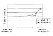
- FIG. 4 is a graph showing the relationship between the position in the gas flow direction, the gas permeability of the cell substrate, and the temperature of the cell module in a cell module in which fuel gas and oxidant gas are in parallel flow.
- (A) is a graph which shows the relationship between the position of the gas flow direction in a cell module, and the gas permeability of a cell substrate
- (b) shows the relationship between the position of the gas flow direction in a cell module, and the temperature of a cell module. It is a graph.
- FIG. 5 is a graph showing the relationship between the position in the gas flow direction and the temperature of the cell module in a cell module in which fuel gas and oxidant gas are in parallel flow.
- FIG. 6 is a graph showing the relationship between the position in the gas flow direction, the gas permeability of the cell substrate, and the temperature of the cell module in the cell module in which the fuel gas and the oxidant gas are counterflows.
- FIG. 8 is a diagram illustrating a method for manufacturing the cell module according to the first embodiment.
- (A) is a schematic sectional drawing which shows the cell substrate which has a uniform gas permeability
- (b) is a schematic sectional drawing which shows the cell substrate to which the compression process was performed.
- FIG. 9 is a diagram illustrating a method for manufacturing the cell module according to the second embodiment.
- A is a schematic sectional drawing which shows the cell substrate which has uniform gas permeability
- (b) is a schematic sectional drawing which shows the cell substrate by which the notch process was performed.
- FIG. 10 is a diagram illustrating a method for manufacturing the cell module according to the third embodiment.
- A) is a schematic sectional drawing which shows the cell board
- (b) is a schematic sectional drawing which shows the state before penetrating a porous board to a cell board
- FIG. 11 is a diagram illustrating a method for manufacturing the cell module according to the fourth embodiment.
- A) is a schematic sectional drawing which shows the cell board
- (b) is a schematic sectional drawing which shows the state before penetrating a porous board to a cell board
- FIG. 12 is a diagram illustrating a method for manufacturing the cell module according to the fifth embodiment.
- A is schematic sectional drawing which shows the state before joining a low-permeability structure and a high-permeability structure
- (b) is a cell formed by joining a low-permeability structure and a high-permeability structure.
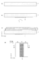
- FIG. 13 is a diagram illustrating a method for manufacturing the cell module according to the sixth embodiment.
- (A) is a schematic sectional drawing which shows the cell substrate which has uniform gas permeability
- (b) is a schematic sectional drawing which shows the state which joined the gas penetration obstruction member to the cell substrate.
- (C) is a schematic cross-sectional view taken along the line CC of (d), showing a state in which an air electrode, a solid electrolyte, and a fuel electrode are laminated on a cell substrate provided with a gas intrusion hindering member.
- (D) is a bottom view showing the cell module of the present embodiment.
- the cell module 10 includes a cell substrate 1 having gas permeability. Further, the cell module 10 is formed on the cell substrate 1, either the fuel electrode or the air electrode 2, the solid electrolyte 3 formed on the one electrode 2, and the solid electrolyte 3. The other electrode 4 is provided.
- the cell module 10 includes a fuel electrode interconnector 21 (fuel electrode separator) and an air electrode interconnector 22 (air electrode separator). It is pinched.
- the fuel electrode interconnector 21 includes a plurality of fuel gas channels 21a
- the air electrode interconnector 22 includes a plurality of oxidant gas channels 22a.
- the fuel gas channel 21a and the oxidant gas channel 22a are a large number of linear channels (parallel channels) arranged in parallel to each other.
- the cross-sectional shapes of the flow paths (fuel gas flow path 21a and oxidant gas flow path 22a) provided in the fuel electrode interconnector 21 and the air electrode interconnector 22 are composed of convex portions called ribs and concave portions called channels. .
- one of the ribs of the fuel electrode interconnector 21 and the air electrode interconnector 22 comes into contact with the cell substrate 1, whereby electrons are conducted between the interconnector and the cell substrate 1.
- the other ribs of the fuel electrode interconnector 21 and the air electrode interconnector 22 are brought into contact with the other electrode 4, whereby electrons are conducted between the interconnector and the other electrode 4.
- the fuel gas flowing through the fuel gas flow channel 21a and the oxidant gas flowing through the oxidant gas flow channel 22a may be a counter flow that flows oppositely in the plane of the cell module 10. Further, the fuel gas and the oxidant gas may be a parallel flow (co-flow) that flows in the same direction in the plane of the cell module 10.
- the cell module 10 will be described below with one electrode 2 as a fuel electrode and the other electrode 4 as an air electrode.
- the fuel electrode interconnector 21 is in contact with the cell substrate 1 and the air electrode interconnector 22 is in contact with the air electrode.
- FIG. 1A in the case of a parallel flow in which the fuel gas and the oxidant gas flow in the same direction in the plane of the cell module 10, as shown in FIG. Cell module temperature is highest. That is, in the case of the parallel flow type, heat generated by the battery reaction and heat generated by Joule heat are transmitted to the downstream side by the effect of convective heat transfer by the working fluid. Therefore, the temperature of the cell module rises from the inlet to the outlet of the gas flow path.
- FIG. 1 (b) in the case of the counter flow in which the fuel gas and the oxidant gas flow in opposition in the plane of the cell module 10, a temperature distribution different from that in the parallel flow is shown.
- a portion where the cell module temperature is high occurs in the central portion 1b, not in the inlet portion 1a and the outlet portion 1c of the oxidant gas and fuel gas in the cell module 10.
- the oxidant gas outlet side becomes the fuel gas inlet side, and the low-temperature fuel gas flows on the oxidant gas outlet side. Therefore, the cell module temperature in the central portion 1b is more likely to rise intensively than the outlet portion 1c and the inlet portion 1a.
- the gas permeability of the cell substrate 1 in the portion corresponding to the high temperature portion in the cell module 10 is reduced. That is, in the case of parallel flow, the gas permeability of the outlet portion 1c of the fuel gas in the cell substrate 1 is set lower than the gas permeability of the portion other than the outlet portion 1c in the cell substrate 1.
- the single cell covers the insufficient power generation amount on the upstream side, so that the power generation amount in the upstream portion (inlet portion 1a) increases.
- the temperature rises at the inlet portion 1a which has been low temperature, and the temperature falls at the outlet portion 1c, so that the high temperature concentration at the outlet portion 1c is alleviated and the temperature of the entire cell module can be made uniform.
- the porosity is increased on the downstream side of the gas flow path to increase the gas permeability.
- the gas permeability is set low on the downstream side of the gas flow path. Therefore, as shown in FIGS. 4B and 5, the temperature at the outlet portion 1 c of the cell module 10 is lowered as compared with the configuration of Patent Document 1, so that the state below the operating limit temperature is maintained. Can do. As a result, thermal deterioration of the cell module 10 can be suppressed and durability can be improved.
- the gas permeability of the central portion 1b of the cell substrate 1 in the gas flow direction is expressed by the fuel gas inlet portion 1a and the cell substrate 1 It is set lower than the gas permeability of the outlet 1c.
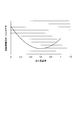
- FIG. 7 shows the relationship between the gas permeability of the cell substrate and the maximum temperature in the portion where the temperature of the cell module is high. Specifically, in the case of parallel flow, the relationship between the gas permeability of the fuel gas outlet 1c in the cell substrate 1 and the maximum temperature is shown. In the case of the counter flow, the relationship between the gas permeability of the central portion 1b of the cell substrate 1 in the gas flow direction and the maximum temperature is shown.
- a gas permeability of 1.0 indicates that the gas permeability is the same as that of other locations on the cell substrate.
- a gas permeability of 0.6 means that 60% of gas permeates, that is, the amount of gas permeation decreases by 40%.
- the gas permeability at which the maximum temperature of the cell module is lowest is around 0.6. Therefore, in consideration of the manufacturing conditions of the cell substrate and the temperature lowering effect of the cell module, the gas permeability is preferably 0.4 to 0.8, more preferably 0.5 to 0.7. In other words, in the cell substrate 1, the gas permeability of the portion having a low gas permeability is preferably 40 to 80% lower, and more preferably 30 to 50% lower than the gas permeability of the other portions.
- the method for measuring the gas permeability of the cell substrate 1 is not particularly limited as long as the relative value between the gas permeability in the portion where the gas permeability is low and the gas permeability in other portions can be obtained.
- the gas permeability of the cell substrate 1 can be measured using, for example, a differential pressure type gas permeability evaluation apparatus.
- the gas permeability of the cell substrate 1 can be lowered by providing a dense portion formed by compressing the cell substrate 1. That is, the cell substrate 1 having a uniform gas permeability is formed by compressing and denting a portion where the gas permeability is desired to be lowered, thereby changing the gas permeability.
- the portion of the cell substrate 1 having a uniform gas permeability is compressed from the lower surface of the cell substrate 1 with respect to the cell substrate 1 having a uniform gas permeability. Then, the dense portion 1d is formed by recessing. And as shown in FIG.8 (c), the cell module 10 is laminated
- stacking method of the fuel electrode 2, the solid electrolyte 3, and the air electrode 4 is not specifically limited, A well-known method can be used.
- Such a dense portion 1d is compressed by the cell substrate 1 and increases in density, so that it is difficult for fuel gas to enter. Therefore, in the dense portion 1d, the fuel gas permeability is reduced, and the fuel gas entering the fuel electrode 2 is reduced. Therefore, since the power generation amount of the single cell facing the dense portion subjected to such compression processing is reduced, the maximum temperature of the cell module can be lowered. Further, by adjusting the compression amount of the dense portion 1d, that is, the thickness and density of the dense portion, a desired gas permeability can be easily obtained.
- the dense portion 1 d may be formed on the entire central portion 1 b of the cell substrate 1. In the case of parallel flow, the dense portion 1 d may be formed on the entire outlet portion 1 c of the cell substrate 1.
- the dense portion 1d is formed by being compressed and recessed from the lower surface of the cell substrate 1, the recessed portion is not in contact with the rib of the fuel electrode interconnector 21, and the cell substrate 1 and the fuel There is a possibility that sufficient conduction with the polar interconnector 21 cannot be ensured.
- the dense portion 1d is formed in a long shape along the fuel gas flow direction (Z-axis direction). Furthermore, it is preferable to provide a plurality of dense portions 1d at intervals in a direction perpendicular to the Z-axis direction (X-axis direction). Thus, by providing a plurality of dense portions 1d at intervals, the cell substrate 1 and the fuel electrode interconnector 21 are electrically connected even in a portion where the gas permeability is to be reduced. Therefore, it is possible to ensure electrical connection between the cell substrate 1 and the fuel electrode interconnector 21. In addition, it is possible to obtain a desired gas permeability by providing a plurality of dense portions 1d at intervals and adjusting the width, interval, and density of the dense portions 1d.
- the cell substrate 1 is not particularly limited as long as it has gas permeability and sufficient strength as a support, but a cell substrate having a high electrical conductivity is used. Is preferred.
- a plate-shaped member made of a corrosion-resistant alloy, corrosion-resistant steel, stainless steel, or the like containing nickel (Ni) or chromium (Cr) and having a large number of voids can be applied.
- a punching metal substrate, an etching metal substrate, an expanded metal substrate, a foamed metal body, a metal powder sintered body, a metal mesh such as a wire mesh, a metal nonwoven fabric, or the like made of the above material can be used. Moreover, these may laminate
- the fuel electrode 2 one that is strong in a reducing atmosphere, permeates the fuel gas, has high electrical conductivity, and has a catalytic action for converting hydrogen molecules into protons can be suitably used.
- a metal such as nickel (Ni) may be applied alone, but a cermet mixed with an oxygen ion conductor typified by yttria stabilized zirconia (YSZ) is applied. It is preferable to do. By using such a material, the reaction area increases and the electrode performance can be improved.
- a ceria solid solution such as samaria doped ceria (SDC) or gadria doped ceria (GDC) can be applied instead of yttria stabilized zirconia (YSZ).
- the air electrode 4 one that is strong in an oxidizing atmosphere, permeates the oxidant gas, has high electrical conductivity, and has a catalytic action for converting oxygen molecules into oxide ions can be suitably used.
- the air electrode 4 may be made of an electrode catalyst or a cermet of an electrode catalyst and an electrolyte material.
- a metal such as silver (Ag) or platinum (Pt) may be used as the electrode catalyst, but lanthanum strontium cobaltite (La 1-x Sr x CoO 3 : LSC) or lanthanum strontium cobalt ferrite ( La 1-x Sr x Co 1 -y Fe y O 3: LSCF), samarium strontium cobaltite (Sm x Sr 1-x CoO 3: SSC), lanthanum strontium manganite (La 1-x Sr x MnO 3: LSM It is preferable to apply a perovskite oxide such as However, it is not limited to these, and conventionally known air electrode materials can be applied.
- examples of the electrolyte material include, but are not limited to, cerium oxide (CeO 2 ), zirconium oxide (ZrO 2 ), titanium oxide (TiO 2 ), and lanthanum oxide (La 2 O 3 ). It is not a thing, but the mixture with oxides, such as various stabilized zirconia and a ceria solid solution, can be used suitably.
- solid electrolyte 3 what has gas impermeability and the ability to let oxygen ion pass without passing an electron can be used conveniently.
- the constituent material of the solid electrolyte include yttria (Y 2 O 3 ), neodymium oxide (Nd 2 O 3 ), samaria (Sm 2 O 3 ), gadria (Gd 2 O 3 ), and scandia (Sc 2 O 3 ). It is possible to apply stabilized zirconia in which these are dissolved.
- ceria solid solutions such as samaritan doped ceria (SDC), yttria doped ceria (YDC), and gadria doped ceria (GDC), bismuth oxide (Bi 2 O 3 ), lanthanum strontium magnesium gallate (La 1-x Sr x Ga 1-y Mg y O 3 : LSMG) or the like can also be applied.
- SDC samaritan doped ceria
- YDC yttria doped ceria
- GDC gadria doped ceria
- Bi 2 O 3 bismuth oxide
- La 1-x Sr x Ga 1-y Mg y O 3 : LSMG lanthanum strontium magnesium gallate
- the cell module 10 includes the cell substrate 1 having gas permeability, one electrode 2 of the fuel electrode and the air electrode formed on the cell substrate 1, and one electrode 2.
- the solid electrolyte 3 formed on the top and the other electrode 4 formed on the solid electrolyte 3 are provided.
- the gas permeability of the central portion 1b of the cell substrate 1 in the gas flow direction is higher than the gas permeability of the inlet portion 1a and the outlet portion 1c of the cell substrate 1. It has a low configuration.
- the gas permeability of the outlet portion 1c of the cell substrate 1 in the gas flow direction is other than the outlet portion 1c of the cell substrate 1.
- the gas permeability is lower than that of the portion. Therefore, since the amount of power generation of the single cell facing the portion where the gas permeability in the cell substrate 1 is reduced, the maximum temperature of the cell module can be lowered and the durability of the cell module can be improved.
- the gas permeability of the cell substrate 1 is lowered by providing a dense portion 1d formed by compressing the cell substrate 1. Since the dense portion 1d is formed by compressing and denting the portion where the gas permeability is to be lowered in this way, the gas permeability can be lowered by a simple method.
- the cell substrate 1 is divided into three equal parts along the gas flow direction (Z-axis direction) and defined in detail from the upstream side of the fuel gas as the inlet portion 1a, the central portion 1b, and the outlet portion 1c.
- the present embodiment is not limited to this aspect. That is, the cell substrate 1 is divided into three or more parts in the gas flow direction (Z-axis direction), the portion including the fuel gas inlet is defined as the inlet portion 1a, and the portion including the fuel gas outlet is defined as the outlet portion 1c. You may prescribe
- the cell module of the present embodiment is configured so that the gas permeability of the central portion 1b of the cell substrate 1 is lower than the gas permeability of the inlet portion 1a and the outlet portion 1c. It is the same as the form.
- the gas permeability of the outlet portion 1c of the cell substrate 1 is set to be lower than the gas permeability of portions other than the outlet portion 1c, as in the first embodiment.
- This embodiment is different from the first embodiment in the method for changing the gas permeability of the cell substrate 1.
- a method for reducing the gas permeability at the central portion 1b of the cell substrate 1 will be described.
- a method for reducing the gas permeability at the outlet portion 1c can be similarly performed.
- the gas permeability of the cell substrate 1 can be adjusted by providing the cell substrate 1 with a groove-shaped notch. That is, with respect to the cell substrate 1 having a uniform gas permeability, grooves are formed by cutting the surfaces of the portions (for example, the inlet portion 1a and the outlet portion 1c) where the gas permeability is desired to be increased, and the change in the gas permeability. It is something that has
- FIGS. 9A and 9B a portion of the cell substrate 1 having a uniform gas permeability that is desired to increase the gas permeability is cut out by cutting away from the lower surface. A notch is provided, and the portion where the gas permeability is to be reduced is maintained without being cut.
- the cell module 10 is laminated
- stacking method of the fuel electrode 2, the solid electrolyte 3, and the air electrode 4 is not specifically limited, A well-known method can be used.
- the fuel gas can easily enter the cell substrate 1 of the inlet portion 1a and the outlet portion 1c provided with the notch 1e, Improves permeability.
- the cell substrate 1 in the central portion 1b where the notch 1e is not provided maintains the gas permeability as it is. Therefore, when viewed from the whole cell module, the gas permeability of the central portion 1b of the cell substrate 1 is relatively reduced. Therefore, since the power generation amount of the single cell facing the central portion 1b where such notch processing is not performed is reduced, the maximum temperature of the cell module can be lowered.
- the amount of reduction in gas permeability can be easily adjusted by adjusting the width of the notch and the depth of excision.
- the notch 1e may be formed in the entire portion where the gas permeability is desired to be increased. That is, in the case of the counter flow, the notch 1e may be formed in the entire inlet portion 1a and outlet portion 1c of the cell substrate 1. Further, in the case of parallel flow, a notch 1e may be formed in the entire inlet portion 1a and central portion 1b of the cell substrate 1. However, since the notch 1e is formed by partially cutting the lower surface of the cell substrate 1, the cut portion is not in contact with the rib of the fuel electrode interconnector 21, and the cell substrate 1 and the fuel electrode There is a possibility that sufficient conduction with the connector 21 cannot be ensured. Further, when the notch 1e is increased, the strength of the cell substrate may be excessively reduced.
- the notch 1e is formed in a long shape along the fuel gas flow direction (Z-axis direction). Furthermore, it is preferable to provide a plurality of cutouts 1e at intervals in a direction perpendicular to the Z-axis direction (X-axis direction).
- the cell substrate 1 and the fuel electrode interconnector 21 are electrically connected to each other, and it is possible to ensure electrical conduction therebetween.
- the gas permeability of the cell substrate 1 is adjusted by providing the cell substrate 1 with a groove-shaped notch.
- the gas permeability of the cell substrate 1 is adjusted by reducing the apparent volume of the cell substrate 1. Therefore, the inlet portion 1a and the outlet portion 1c of the cell substrate 1 are notched, and the apparent volume of the cell substrate 1 made of a porous body is reduced, thereby increasing the gas permeability of the inlet portion 1a and the outlet portion 1c, In particular, the gas permeability of the central portion 1b can be reduced.
- This embodiment is different from the first embodiment in the method for changing the gas permeability of the cell substrate 1.
- a method for reducing the gas permeability at the central portion 1b of the cell substrate 1 will be described.
- a method for reducing the gas permeability at the outlet portion 1c can be similarly performed.
- the gas permeability of the cell substrate 1 can be lowered by lowering the porosity of the porous body constituting the cell substrate 1. That is, for the cell substrate 1 having a uniform gas permeability, a porous plate is additionally compressed in a portion where the gas permeability is desired to be lowered and penetrated into the cell substrate to change the gas permeability. .
- the cell substrate 1 having a uniform gas permeability is porous from the lower surface of the cell substrate 1 in a portion where the gas permeability is desired to be reduced.
- the penetration portion 1 g is formed.
- the bottom surface of the cell substrate 1 subjected to the penetration processing can be smoothed. Therefore, by laminating the fuel electrode 2, the solid electrolyte 3 and the air electrode 4 on the bottom surface.
- the cell module 10 is obtained.
- stacking method of the fuel electrode 2, the solid electrolyte 3, and the air electrode 4 is not specifically limited, A well-known method can be used.
- Such a penetration 1g makes it difficult for fuel gas to enter because the porous plate 1f penetrates the cell substrate 1 and the porosity is lowered. Therefore, in the penetration portion 1g, the fuel gas permeability is reduced, and the fuel gas entering the fuel electrode 2 is reduced. Therefore, since the power generation amount of the single cell facing the penetration portion 1g is reduced, the maximum temperature of the cell module can be lowered. In addition, it is possible to easily obtain a desired gas permeability by adjusting the thickness of the porous plate 1f for forming the penetration portion 1g.
- the porous plate 1 f is compressed from the surface of the cell substrate 1, and the porous plate 1 f is penetrated into the cell substrate 1, thereby forming the penetration portion 1 g. Therefore, since both the upper surface and the lower surface of the cell substrate 1 can be made smooth, the fuel electrode 2, the solid electrolyte 3 and the air electrode 4 are formed on the lower surface of the cell substrate 1, as shown in FIG. be able to. The fuel electrode 2, the solid electrolyte 3, and the air electrode 4 may be formed on the upper surface of the cell substrate 1.
- the cell module of this embodiment can further improve the power generation performance compared to the first and second embodiments.
- the porous plate 1f like the cell substrate 1, is made of a corrosion-resistant alloy, corrosion-resistant steel, stainless steel, or the like containing nickel (Ni) or chromium (Cr), and has a plate shape having a large number of voids. Can be used. Specifically, a punching metal substrate, an etching metal substrate, an expanded metal substrate, a foamed metal body, a metal powder sintered body, a metal mesh such as a wire mesh, a metal nonwoven fabric, or the like made of the above material can be used. Further, the shape of the porous plate 1f is not limited to the frustum shape as shown in FIG. 10, and may be, for example, a rectangular parallelepiped shape.
- the gas permeability of the cell substrate 1 is lowered by lowering the porosity of the porous body constituting the cell substrate 1 as in the third embodiment.
- the cell substrate 1 having a uniform gas permeability is porous from the lower surface of the cell substrate 1 in a portion where the gas permeability is desired to be reduced.
- 1 g of penetration parts are formed by compressing the board 1f and penetrating the porous board 1f inside.
- the cell module 10 is obtained by laminating
- the penetration part 1g is formed in a long shape along the fuel gas flow direction (Z-axis direction). Further, a plurality of penetration portions 1g are provided at intervals in a direction perpendicular to the Z-axis direction (X-axis direction). Thus, it becomes possible to obtain a desired gas permeability by providing a plurality of penetration portions 1g at intervals and adjusting the width and interval of the penetration portions 1g.
- the ribs of the fuel electrode interconnector 21 can be compared with the cell substrates of the first and second embodiments. A large contact area is secured. Therefore, the cell module of this embodiment can further improve the power generation performance compared to the first and second embodiments.
- This embodiment is different from the first embodiment in the method for changing the gas permeability of the cell substrate 1.
- a method for reducing the gas permeability at the central portion 1b of the cell substrate 1 will be described.
- a method for reducing the gas permeability at the outlet portion 1c can be similarly performed.
- the gas permeability of the cell substrate 1 can be lowered by lowering the porosity of the porous body constituting the cell substrate 1.
- the gas permeability of the cell substrate 1 uses two types of porous structures in which the gas permeability is changed by changing the porosity. The gas permeability is adjusted by superimposing these.
- the cell substrate 1 of the present embodiment uses a low-transmittance structure 1h and a high-transmittance structure 1i that has a smaller gas transmission amount than the low-transmittance structure 1h. Yes.
- the thickness of the central portion 1b in the low transmittance structure 1h is increased, and the thickness of the central portion 1b in the high transmittance structure 1i is decreased. That is, with respect to the central portion 1b, the thickness of the low transmittance structure 1h in the stacking direction (Y-axis direction) is larger than the thickness of the high transmittance structure 1i.
- the thickness of the inlet portion 1a and the outlet portion 1c in the low transmittance structure 1h is relatively small, and the thickness of the inlet portion 1a and the outlet portion 1c in the high transmittance structure 1i is relatively large. That is, regarding the inlet portion 1a and the outlet portion 1c, the thickness of the low transmittance structure 1h in the stacking direction (Y-axis direction) is smaller than the thickness of the high transmittance structure 1i.
- the convex central portion 1b in the low transmittance structure 1h is laminated so as to be inserted into the concave central portion 1b in the high transmittance structure 1i.
- the cell substrate 1 according to the embodiment is obtained.
- the cell module 10 is obtained by laminating the fuel electrode 2, the solid electrolyte 3, and the air electrode 4 on the obtained cell substrate 1.
- stacking method of the fuel electrode 2, the solid electrolyte 3, and the air electrode 4 is not specifically limited, A well-known method can be used.
- the permeability of the fuel gas is reduced in the portion where the low permeability structure 1h is thick, and the fuel gas entering the fuel electrode 2 is reduced. Therefore, since the power generation amount of the single cell facing the thick part of the low transmittance structure 1h is reduced, the maximum temperature of the cell module can be lowered. Further, by adjusting the thickness of the low transmittance structure 1h and the gas permeability of the low transmittance structure 1h and the high transmittance structure 1i, a desired gas permeability can be easily obtained.
- the fuel electrode interconnector 21 is compared with the cell substrates of the first and second embodiments. A large contact area with the ribs is ensured. Therefore, the cell module of this embodiment can further improve the power generation performance compared to the first and second embodiments.
- This embodiment is different from the first embodiment in the method for changing the gas permeability of the cell substrate 1.
- a method for reducing the gas permeability at the central portion 1b of the cell substrate 1 will be described.
- a method for reducing the gas permeability at the outlet portion 1c can be similarly performed.
- the gas permeability of the cell substrate 1 can be lowered by providing a gas intrusion hindering member on the cell substrate 1.
- a gas penetration obstruction member is installed on the surface of the part where the gas permeability is desired to be reduced, and the gas penetration is changed by suppressing the gas penetration of the part.
- the gas intrusion hindering member 1j is provided on the lower surface of the portion where the gas permeability is desired to be reduced with respect to the cell substrate 1 having a uniform gas permeability.
- the cell module 10 is obtained by laminating
- stacking method of the fuel electrode 2, the solid electrolyte 3, and the air electrode 4 is not specifically limited, A well-known method can be used.
- the gas intrusion obstruction member 1j is not particularly limited as long as it is a member that suppresses the invasion of fuel gas to the cell substrate 1.
- the gas intrusion hindering member 1j is made of the same material as that of the cell substrate 1, but a denser structure may be used, and a plate material may be provided with a large number of through holes.
- a punching metal substrate, an etching metal substrate, an expanded metal substrate, a foam metal body, a metal powder sintered body, a metal mesh such as a wire mesh, a metal nonwoven fabric, or the like can be used.
- the gas intrusion hindrance member 1j may be bonded to the lower surface of the cell substrate 1 or may be partially embedded in the cell substrate 1.
- the contact area of the interconnector is increased with respect to a place where gas intrusion in the cell substrate 1 is desired to be suppressed, and the amount of fuel gas entering the cell substrate 1 is suppressed.
- the contact area of the interconnector is reduced at the location where gas penetration into the cell substrate 1 is desired to be increased, and the amount of fuel gas entering the cell substrate 1 is increased.
Landscapes
- Life Sciences & Earth Sciences (AREA)
- Engineering & Computer Science (AREA)
- Manufacturing & Machinery (AREA)
- Sustainable Development (AREA)
- Sustainable Energy (AREA)
- Chemical & Material Sciences (AREA)
- Chemical Kinetics & Catalysis (AREA)
- Electrochemistry (AREA)
- General Chemical & Material Sciences (AREA)
- Fuel Cell (AREA)
Abstract
Description
本実施形態に係るセルモジュール10は、図1に示すように、ガス透過性を有するセル基板1を備えている。さらにセルモジュール10は、セル基板1上に形成される、燃料極及び空気極のいずれか一方の電極2と、当該一方の電極2上に形成される固体電解質3と、固体電解質3上に形成される他方の電極4とを備えている。
次に、第二実施形態に係る固体酸化物形燃料電池用セルモジュールについて、図面に基づき詳細に説明する。なお、第一実施形態と同一構成には同一符号を付し、重複する説明は省略する。
次に、第三実施形態に係る固体酸化物形燃料電池用セルモジュールについて、図面に基づき詳細に説明する。なお、第一実施形態と同一構成には同一符号を付し、重複する説明は省略する。
次に、第四実施形態に係る固体酸化物形燃料電池用セルモジュールについて、図面に基づき詳細に説明する。なお、第三実施形態と同一構成には同一符号を付し、重複する説明は省略する。
次に、第五実施形態に係る固体酸化物形燃料電池用セルモジュールについて、図面に基づき詳細に説明する。なお、第一実施形態と同一構成には同一符号を付し、重複する説明は省略する。
次に、第六実施形態に係る固体酸化物形燃料電池用セルモジュールについて、図面に基づき詳細に説明する。なお、第一実施形態と同一構成には同一符号を付し、重複する説明は省略する。
1a 入口部
1b 中央部
1c 出口部
1e 切り欠き
1j ガス侵入障害部材
2 燃料極
3 固体電解質
4 空気極
10 セルモジュール
20 固体酸化物形燃料電池
21 燃料極インターコネクター
22 空気極インターコネクター
Claims (9)
- ガス透過性を有するセル基板と、
前記セル基板上に形成される、燃料極及び空気極のいずれか一方の電極と、
前記一方の電極上に形成される固体電解質と、
前記固体電解質上に形成される他方の電極と、
を備え、
燃料ガスと酸化剤ガスとを対向して流す場合、ガス流れ方向における前記セル基板の中央部のガス透過率が、前記セル基板の入口部及び出口部のガス透過率よりも低いことを特徴とする固体酸化物形燃料電池用セルモジュール。 - ガス透過性を有するセル基板と、
前記セル基板上に形成される、燃料極及び空気極のいずれか一方の電極と、
前記一方の電極上に形成される固体電解質と、
前記固体電解質上に形成される他方の電極と、
を備え、
燃料ガスと酸化剤ガスとを並行して流す場合、ガス流れ方向における前記セル基板の出口部のガス透過率が、前記セル基板の前記出口部以外の部分のガス透過率よりも低いことを特徴とする固体酸化物形燃料電池用セルモジュール。 - 前記セル基板のガス透過率は、前記セル基板を圧縮してなる緻密部を設けることで低下させることを特徴とする請求項1又は2に記載の固体酸化物形燃料電池用セルモジュール。
- 前記セル基板のガス透過率は、前記セル基板に溝形状の切り欠きを設けることで調整することを特徴とする請求項1又は2に記載の固体酸化物形燃料電池用セルモジュール。
- 前記セル基板のガス透過率は、前記セル基板の見かけ体積を下げることにより調整することを特徴とする請求項1又は2に記載の固体酸化物形燃料電池用セルモジュール。
- 前記セル基板のガス透過率は、前記セル基板を構成する多孔体の気孔率を下げることにより低下させることを特徴とする請求項1又は2に記載の固体酸化物形燃料電池用セルモジュール。
- 前記セル基板のガス透過率は、前記セル基板にガス侵入障害部材を設けることで低下させることを特徴とする請求項1又は2に記載の固体酸化物形燃料電池用セルモジュール。
- 前記セル基板において、ガス透過率が低い部分のガス透過率は、他の部分のガス透過率よりも30~50%低いことを特徴とする請求項1乃至7のいずれか一項に記載の固体酸化物形燃料電池用セルモジュール。
- 請求項1乃至8のいずれか一項に記載の固体酸化物形燃料電池用セルモジュールと、
前記固体酸化物形燃料電池用セルモジュールを挟持するインターコネクターと、
を備えることを特徴とする固体酸化物形燃料電池。
Priority Applications (7)
| Application Number | Priority Date | Filing Date | Title |
|---|---|---|---|
| CN201580080229.3A CN107615542B (zh) | 2015-05-21 | 2015-05-21 | 固体氧化物型燃料电池用单元模块和使用了该固体氧化物型燃料电池用单元模块的固体氧化物型燃料电池 |
| EP15892593.3A EP3300151B1 (en) | 2015-05-21 | 2015-05-21 | Solid oxide fuel cell |
| BR112017024931-6A BR112017024931B1 (pt) | 2015-05-21 | 2015-05-21 | Módulo celular para célula de combustível de oxido sólido e célula de combustível de oxido solido utilizando o mesmo |
| JP2017518695A JP6504249B2 (ja) | 2015-05-21 | 2015-05-21 | 固体酸化物形燃料電池用セルモジュール及びそれを用いた固体酸化物形燃料電池 |
| CA2986716A CA2986716C (en) | 2015-05-21 | 2015-05-21 | Cell module for solid oxide fuel cell, and solid oxide fuel cell using same |
| US15/575,513 US10205176B2 (en) | 2015-05-21 | 2015-05-21 | Cell module for solid oxide fuel cell, and solid oxide fuel cell using same |
| PCT/JP2015/064553 WO2016185594A1 (ja) | 2015-05-21 | 2015-05-21 | 固体酸化物形燃料電池用セルモジュール及びそれを用いた固体酸化物形燃料電池 |
Applications Claiming Priority (1)
| Application Number | Priority Date | Filing Date | Title |
|---|---|---|---|
| PCT/JP2015/064553 WO2016185594A1 (ja) | 2015-05-21 | 2015-05-21 | 固体酸化物形燃料電池用セルモジュール及びそれを用いた固体酸化物形燃料電池 |
Publications (1)
| Publication Number | Publication Date |
|---|---|
| WO2016185594A1 true WO2016185594A1 (ja) | 2016-11-24 |
Family
ID=57319628
Family Applications (1)
| Application Number | Title | Priority Date | Filing Date |
|---|---|---|---|
| PCT/JP2015/064553 Ceased WO2016185594A1 (ja) | 2015-05-21 | 2015-05-21 | 固体酸化物形燃料電池用セルモジュール及びそれを用いた固体酸化物形燃料電池 |
Country Status (7)
| Country | Link |
|---|---|
| US (1) | US10205176B2 (ja) |
| EP (1) | EP3300151B1 (ja) |
| JP (1) | JP6504249B2 (ja) |
| CN (1) | CN107615542B (ja) |
| BR (1) | BR112017024931B1 (ja) |
| CA (1) | CA2986716C (ja) |
| WO (1) | WO2016185594A1 (ja) |
Cited By (4)
| Publication number | Priority date | Publication date | Assignee | Title |
|---|---|---|---|---|
| WO2018165682A1 (de) * | 2017-03-16 | 2018-09-20 | Plansee Se | Poröses formteil für elektrochemisches modul |
| CN111525148A (zh) * | 2020-04-17 | 2020-08-11 | 珠海格力电器股份有限公司 | 单极板、双极板及燃料电池 |
| JP2022125626A (ja) * | 2021-02-17 | 2022-08-29 | 森村Sofcテクノロジー株式会社 | 電気化学反応単セルおよび電気化学反応セルスタック |
| WO2025164684A1 (ja) * | 2024-01-30 | 2025-08-07 | 京セラ株式会社 | 電気化学セル、電気化学セル装置、モジュールおよびモジュール収容装置 |
Families Citing this family (2)
| Publication number | Priority date | Publication date | Assignee | Title |
|---|---|---|---|---|
| US10283794B2 (en) * | 2015-12-09 | 2019-05-07 | Syracuse University | Electricity and syngas co-generation system using porous solid oxide fuel cells |
| AU2024240223A1 (en) * | 2023-03-22 | 2025-10-16 | Suzano S.A. | Low viscosity cm-mfc |
Citations (4)
| Publication number | Priority date | Publication date | Assignee | Title |
|---|---|---|---|---|
| JP2008135272A (ja) * | 2006-11-28 | 2008-06-12 | Kyocera Corp | 平板型燃料電池のインターコネクタ及びその製法、平板型燃料電池、平板型燃料電池スタック並びにその製法 |
| JP2011017055A (ja) * | 2009-07-09 | 2011-01-27 | Toshiba Corp | 電気化学セル |
| JP2012094427A (ja) * | 2010-10-28 | 2012-05-17 | Kyocera Corp | 固体酸化物形燃料電池セルおよび燃料電池 |
| WO2015045682A1 (ja) * | 2013-09-25 | 2015-04-02 | 株式会社デンソー | 燃料電池用アノードおよび燃料電池単セル |
Family Cites Families (8)
| Publication number | Priority date | Publication date | Assignee | Title |
|---|---|---|---|---|
| US4269642A (en) * | 1979-10-29 | 1981-05-26 | United Technologies Corporation | Method of forming densified edge seals for fuel cell components |
| US5336569A (en) | 1991-03-20 | 1994-08-09 | Ngk Insulators, Ltd. | Power generating equipment |
| US7374838B2 (en) * | 2003-06-10 | 2008-05-20 | Ballard Power Systems Inc. | Electrochemical fuel cell with fluid distribution layer having non-uniform permeability |
| JP2005190684A (ja) * | 2003-12-24 | 2005-07-14 | Toyota Motor Corp | 燃料電池 |
| WO2008003976A1 (en) * | 2006-07-07 | 2008-01-10 | Ceres Intellectual Property Company Limited | Metal substrate for fuel cells |
| US9786929B2 (en) * | 2008-09-18 | 2017-10-10 | Panasonic Intellectual Property Management Co., Ltd. | Fuel cell and fuel cell stack comprising the same |
| EP2834870B1 (en) * | 2012-04-04 | 2015-09-16 | Nissan Motor Co., Ltd. | Membrane electrode assembly, fuel cell, fuel cell stack, and method for manufacturing membrane electrode assembly |
| US20160329587A1 (en) * | 2015-05-07 | 2016-11-10 | Lg Fuel Cell Systems, Inc. | Fuel cell system |
-
2015
- 2015-05-21 US US15/575,513 patent/US10205176B2/en active Active
- 2015-05-21 CA CA2986716A patent/CA2986716C/en active Active
- 2015-05-21 WO PCT/JP2015/064553 patent/WO2016185594A1/ja not_active Ceased
- 2015-05-21 BR BR112017024931-6A patent/BR112017024931B1/pt not_active IP Right Cessation
- 2015-05-21 EP EP15892593.3A patent/EP3300151B1/en active Active
- 2015-05-21 JP JP2017518695A patent/JP6504249B2/ja active Active
- 2015-05-21 CN CN201580080229.3A patent/CN107615542B/zh active Active
Patent Citations (4)
| Publication number | Priority date | Publication date | Assignee | Title |
|---|---|---|---|---|
| JP2008135272A (ja) * | 2006-11-28 | 2008-06-12 | Kyocera Corp | 平板型燃料電池のインターコネクタ及びその製法、平板型燃料電池、平板型燃料電池スタック並びにその製法 |
| JP2011017055A (ja) * | 2009-07-09 | 2011-01-27 | Toshiba Corp | 電気化学セル |
| JP2012094427A (ja) * | 2010-10-28 | 2012-05-17 | Kyocera Corp | 固体酸化物形燃料電池セルおよび燃料電池 |
| WO2015045682A1 (ja) * | 2013-09-25 | 2015-04-02 | 株式会社デンソー | 燃料電池用アノードおよび燃料電池単セル |
Non-Patent Citations (1)
| Title |
|---|
| See also references of EP3300151A4 * |
Cited By (5)
| Publication number | Priority date | Publication date | Assignee | Title |
|---|---|---|---|---|
| WO2018165682A1 (de) * | 2017-03-16 | 2018-09-20 | Plansee Se | Poröses formteil für elektrochemisches modul |
| CN111525148A (zh) * | 2020-04-17 | 2020-08-11 | 珠海格力电器股份有限公司 | 单极板、双极板及燃料电池 |
| JP2022125626A (ja) * | 2021-02-17 | 2022-08-29 | 森村Sofcテクノロジー株式会社 | 電気化学反応単セルおよび電気化学反応セルスタック |
| JP7522679B2 (ja) | 2021-02-17 | 2024-07-25 | 森村Sofcテクノロジー株式会社 | 電気化学反応単セルおよび電気化学反応セルスタック |
| WO2025164684A1 (ja) * | 2024-01-30 | 2025-08-07 | 京セラ株式会社 | 電気化学セル、電気化学セル装置、モジュールおよびモジュール収容装置 |
Also Published As
| Publication number | Publication date |
|---|---|
| JP6504249B2 (ja) | 2019-04-24 |
| EP3300151A1 (en) | 2018-03-28 |
| CA2986716A1 (en) | 2016-11-24 |
| US20180159146A1 (en) | 2018-06-07 |
| CN107615542A (zh) | 2018-01-19 |
| CA2986716C (en) | 2019-03-05 |
| BR112017024931A2 (ja) | 2018-07-31 |
| EP3300151A4 (en) | 2018-03-28 |
| JPWO2016185594A1 (ja) | 2018-03-29 |
| CN107615542B (zh) | 2018-10-12 |
| EP3300151B1 (en) | 2020-07-08 |
| BR112017024931B1 (pt) | 2023-02-28 |
| US10205176B2 (en) | 2019-02-12 |
Similar Documents
| Publication | Publication Date | Title |
|---|---|---|
| JP6504249B2 (ja) | 固体酸化物形燃料電池用セルモジュール及びそれを用いた固体酸化物形燃料電池 | |
| JP5708923B2 (ja) | 燃料電池セル及び燃料電池 | |
| JP5116184B1 (ja) | 燃料電池の構造体 | |
| JP2012190746A (ja) | 燃料電池スタックおよび燃料電池 | |
| JP6279519B2 (ja) | 燃料電池スタックおよび燃料電池単セル | |
| JP7378040B2 (ja) | 膜電極接合体および燃料電池 | |
| JP5198675B1 (ja) | 燃料電池の構造体 | |
| JP4883733B1 (ja) | 燃料電池の構造体 | |
| WO2018199095A1 (ja) | 固体酸化物形燃料電池セル | |
| JP6638834B2 (ja) | 固体酸化物形燃料電池用セルモジュール及びそれを用いた固体酸化物形燃料電池 | |
| JP5408381B2 (ja) | 燃料電池 | |
| US20240363872A1 (en) | Solid oxide cell | |
| US20240417866A1 (en) | Solid oxide cell | |
| WO2015045682A1 (ja) | 燃料電池用アノードおよび燃料電池単セル | |
| JP5417548B2 (ja) | 燃料電池の構造体 | |
| JP2009087876A (ja) | 単室型燃料電池及び単室型燃料電池積層体 | |
| JP2013168227A (ja) | 固体酸化物形燃料電池の製造方法 | |
| US11605821B2 (en) | Solid oxide type fuel battery cell | |
| JP2019179757A (ja) | 金属板、電気化学素子、電気化学モジュール、電気化学装置、エネルギーシステム、固体酸化物形燃料電池、および金属板の製造方法 | |
| JP2009087725A (ja) | 単室型燃料電池及びその製造方法 | |
| JP2009087711A (ja) | 単室型燃料電池及び単室型燃料電池積層体 | |
| JP2014165128A (ja) | 固体酸化物形燃料電池セル |
Legal Events
| Date | Code | Title | Description |
|---|---|---|---|
| 121 | Ep: the epo has been informed by wipo that ep was designated in this application |
Ref document number: 15892593 Country of ref document: EP Kind code of ref document: A1 |
|
| ENP | Entry into the national phase |
Ref document number: 2017518695 Country of ref document: JP Kind code of ref document: A |
|
| WWE | Wipo information: entry into national phase |
Ref document number: 15575513 Country of ref document: US |
|
| ENP | Entry into the national phase |
Ref document number: 2986716 Country of ref document: CA |
|
| NENP | Non-entry into the national phase |
Ref country code: DE |
|
| WWE | Wipo information: entry into national phase |
Ref document number: 2015892593 Country of ref document: EP |
|
| REG | Reference to national code |
Ref country code: BR Ref legal event code: B01A Ref document number: 112017024931 Country of ref document: BR |
|
| ENP | Entry into the national phase |
Ref document number: 112017024931 Country of ref document: BR Kind code of ref document: A2 Effective date: 20171121 |