WO2016186068A1 - Procédé de stérilisation aux ultraviolets, procédé pour fabriquer un produit emballé dans un récipient, et dispositif de stérilisation aux ultraviolets - Google Patents
Procédé de stérilisation aux ultraviolets, procédé pour fabriquer un produit emballé dans un récipient, et dispositif de stérilisation aux ultraviolets Download PDFInfo
- Publication number
- WO2016186068A1 WO2016186068A1 PCT/JP2016/064437 JP2016064437W WO2016186068A1 WO 2016186068 A1 WO2016186068 A1 WO 2016186068A1 JP 2016064437 W JP2016064437 W JP 2016064437W WO 2016186068 A1 WO2016186068 A1 WO 2016186068A1
- Authority
- WO
- WIPO (PCT)
- Prior art keywords
- ultraviolet
- container
- light
- sterilized
- ultraviolet light
- Prior art date
- Legal status (The legal status is an assumption and is not a legal conclusion. Google has not performed a legal analysis and makes no representation as to the accuracy of the status listed.)
- Ceased
Links
Images

Classifications
-
- B—PERFORMING OPERATIONS; TRANSPORTING
- B65—CONVEYING; PACKING; STORING; HANDLING THIN OR FILAMENTARY MATERIAL
- B65B—MACHINES, APPARATUS OR DEVICES FOR, OR METHODS OF, PACKAGING ARTICLES OR MATERIALS; UNPACKING
- B65B55/00—Preserving, protecting or purifying packages or package contents in association with packaging
- B65B55/02—Sterilising, e.g. of complete packages
- B65B55/12—Sterilising contents prior to, or during, packaging
- B65B55/16—Sterilising contents prior to, or during, packaging by irradiation
-
- A—HUMAN NECESSITIES
- A23—FOODS OR FOODSTUFFS; TREATMENT THEREOF, NOT COVERED BY OTHER CLASSES
- A23B—PRESERVATION OF FOODS, FOODSTUFFS OR NON-ALCOHOLIC BEVERAGES; CHEMICAL RIPENING OF FRUIT OR VEGETABLES
- A23B2/00—Preservation of foods or foodstuffs, in general
- A23B2/50—Preservation of foods or foodstuffs, in general by irradiation without heating
- A23B2/53—Preservation of foods or foodstuffs, in general by irradiation without heating with ultraviolet light
-
- A—HUMAN NECESSITIES
- A61—MEDICAL OR VETERINARY SCIENCE; HYGIENE
- A61L—METHODS OR APPARATUS FOR STERILISING MATERIALS OR OBJECTS IN GENERAL; DISINFECTION, STERILISATION OR DEODORISATION OF AIR; CHEMICAL ASPECTS OF BANDAGES, DRESSINGS, ABSORBENT PADS OR SURGICAL ARTICLES; MATERIALS FOR BANDAGES, DRESSINGS, ABSORBENT PADS OR SURGICAL ARTICLES
- A61L2/00—Disinfection or sterilisation of materials or objects, in general; Accessories therefor
- A61L2/02—Disinfection or sterilisation of materials or objects, in general; Accessories therefor using physical processes
- A61L2/08—Radiation
- A61L2/10—Ultraviolet [UV] radiation
-
- B—PERFORMING OPERATIONS; TRANSPORTING
- B65—CONVEYING; PACKING; STORING; HANDLING THIN OR FILAMENTARY MATERIAL
- B65B—MACHINES, APPARATUS OR DEVICES FOR, OR METHODS OF, PACKAGING ARTICLES OR MATERIALS; UNPACKING
- B65B55/00—Preserving, protecting or purifying packages or package contents in association with packaging
- B65B55/02—Sterilising, e.g. of complete packages
- B65B55/04—Sterilising wrappers or receptacles prior to, or during, packaging
- B65B55/08—Sterilising wrappers or receptacles prior to, or during, packaging by irradiation
Definitions
- the present invention relates to a sterilization method using ultraviolet light.
- ultraviolet sterilization Unlike sterilization with chemicals, ultraviolet sterilization has no residue, is highly safe, and hardly changes the irradiated material. Therefore, it is suitable as a sterilizing method for food and medical products that require safety and security. And it is proposed to use ultraviolet sterilization for sterilization in various scenes.
- Patent Document 1 includes a flow path for circulation of an object to be disinfected made of a fluid, the periphery of which is made of a material having permeability to ultraviolet light having a sterilizing action, and the flow path.
- An ultraviolet sterilizer is described which has a light source for emitting an ultraviolet ray having a sterilizing action, and performs sterilization by irradiating the object to be disinfected circulating in the flow path with the ultraviolet ray emitted from the light source.
- Patent Document 2 is a waste water treatment apparatus for treating organic matter in waste water, and is provided with a waste water treatment tank for storing waste water, a light source for irradiating ultraviolet light, and at least one in the waste water treatment tank, from the light source
- a leaky light guide having a light guiding part for guiding irradiated ultraviolet light and a leaked part having a leaked part having a refractive index equal to or higher than that of the light guiding part and causing ultraviolet light to leak from the light guiding part
- an oxygen supply unit for supplying oxygen toward the leaked light guide, wherein organic substances in the waste water are decomposed and removed by ozone (O 3 ) generated by oxygen supplied from the photocatalyst and the oxygen supply unit.
- Waste water treatment equipment is described.
- Patent Document 3 the back surface of the first heat transfer plate and the second heat transfer plate provided with a protective cover that arranges a plurality of ultraviolet LEDs on the surface and covers the ultraviolet LEDs in a watertight state, respectively.
- An ultraviolet-irradiated water treatment apparatus is described in which an LED module in which the ultraviolet LED of the plate and the ultraviolet LED of the second heat transfer plate do not overlap back-to-back is disposed inside the treatment tank.
- Patent Document 4 includes a flow path for circulation of a fluid-to-be-sterilized body composed of a material having permeability to a deep ultraviolet ray of a wavelength of 200 to 350 nm having a sterilizing action, and a flow path of the flow path
- An ultraviolet light source disposed outside and having a light source for emitting the deep ultraviolet light having a sterilizing action, the sterilization target being irradiated with the deep ultraviolet light emitted from the light source to an object to be disinfected circulating in the flow path
- the sterilization apparatus wherein the light source comprises a plurality of "ultraviolet light emitting elements for emitting deep ultraviolet light" on the side surface of a cylindrical or polygonal columnar base, and the optical axis of each ultraviolet light emitting element is the cylindrical or polygonal columnar
- An ultraviolet light emitting element arrangement substrate disposed so as to pass through the central axis of the substrate so that the deep ultraviolet radiation is emitted radially to the central axis; and a cover formed of
- Patent Document 5 includes a light source and a light guide plate on the side of which the light source is disposed, and at least one of the front surface and the back surface of the light guide plate is a light emitting surface that emits light from the light source.
- a surface light emitting device is described in which a surface other than the light emitting surface of the light plate and the side surface on which the light source is disposed is formed as a light shielding surface and emits light having a peak wavelength of 388 nm or less.
- the transmittance of ultraviolet light varies depending on the type of substance. For example, although the ultraviolet light transmittance of pure water is relatively high, the ultraviolet light transmittance decreases in the aqueous solution in which the solute that absorbs the ultraviolet light is dissolved or in the suspension containing suspended substances that absorb or scatter the ultraviolet light. Changes significantly depending on the type and content of solute and suspended matter.
- milk and juice have a thickness (optical path length: the length of light passing through the sample) of 300 mm when the transmittance to ultraviolet light of 253.7 nm in distilled water is 10%. The same thickness is known to be 0.07 mm and 0.5 to 1 mm, respectively. Therefore, when ultraviolet sterilization is attempted on the solution or suspension by the conventional techniques described in Patent Documents 1 to 4, there is a concern that the sterilization will be insufficient.
- the body to be sterilized is in contact with the "ultraviolet-transparent window material" attached to the portion of the ultraviolet irradiation device (or the ultraviolet sterilization device) to which the ultraviolet light is emitted. Since the UV rays are irradiated in this case, the solute components and suspended substances of the body to be disinfected adhere to the window material, and it is necessary to periodically clean the window material by a large-scale method such as water washing and decomposition washing.
- a large-scale method such as water washing and decomposition washing.
- the present invention is directed to a liquid object to be sterilized such as a beverage such as juice or milk, or a liquid pharmaceutical such as drip agent, a nursing food, a paste such as desserts, a jelly or mousse to be sterilized, etc.
- a liquid object to be sterilized such as a beverage such as juice or milk, or a liquid pharmaceutical such as drip agent, a nursing food, a paste such as desserts, a jelly or mousse to be sterilized, etc.
- highly reliable UV sterilization is possible even for an object to be disinfected, which has a low UV transmittance, substantially eliminating the task of cleaning the UV transparent window material in the UV irradiation device, and the risk of recontamination
- the ultraviolet sterilization method comprises a filling step of filling an object to be disinfected in an ultraviolet-permeable container, an ultraviolet irradiation step of irradiating ultraviolet rays from the outside of the container filled with the object to be disinfected by the filling step;
- An ultraviolet sterilization method comprising a sealing step of sealing the container filled with the object to be sterilized airtightly, and from the end of the filling step to the end of the ultraviolet irradiation step after the sealing step is completed.
- the ultraviolet irradiation step and the sealing step are performed in the same aseptic environment.
- the "optical axis of the irradiated ultraviolet light in the ultraviolet transparent container crosses the container" or "the intensity of the ultraviolet light to be irradiated” to control the inside of the container.
- the above ultraviolet sterilization method further includes an ultraviolet shielding step of performing an ultraviolet shielding process on the outer surface of the ultraviolet permeable container sealed in the sealing step, from the viewpoint of storage stability of the body to be sterilized. Is preferred.
- UV-LED UV light emitting diode
- DUV-LED deep ultraviolet light emitting diode
- the method for producing a container-packed article according to an aspect of the present invention is a method for producing a container-packaged stuffed article in which UV sterilized food, cosmetics, quasi-drugs or medicines are enclosed in a container. And a step of filling the container of the body to be sterilized by the ultraviolet sterilization method, ultraviolet ray sterilization and sealing of the container by the ultraviolet sterilization method.
- Each of the pair of partition walls has an ultraviolet ray transmitting window, and is configured to be able to press the ultraviolet ray transmitting container filled with the object to be sterilized with the ultraviolet ray transmitting window.
- the ultraviolet light sources are respectively provided inside the pair of partition walls, and irradiate the ultraviolet light to the ultraviolet ray transmitting container through the ultraviolet ray transmitting window.
- the UV transmission window may have a shape corresponding to the shape of the UV container that is pressed.
- the ultraviolet light source typically includes a plurality of linear or point light sources disposed along the light emitting surface.
- the pair of partition walls may each have an opening closed by the ultraviolet transmission window, and the ultraviolet light source may be configured to be movable inside the opening along the ultraviolet transmission window.
- the object to be sterilized is filled in an ultraviolet permeable container, and ultraviolet rays are irradiated from the outside of the container to perform sterilization. Therefore, the object to be sterilized contacts the window material of the ultraviolet irradiation device or the ultraviolet sterilization device. There is no chance that the window material will get dirty. Therefore, it is not necessary to carry out disassembly and cleaning, and it is possible to always maintain a clean state (a state of high UV transparency) by a simple operation such as the wiping operation of minor dirt such as dust adhesion.
- the sealing step is performed after the filling step is ended until the ultraviolet irradiation step is ended, or the ultraviolet irradiation step and the sealing step are the same. As it is performed in an aseptic environment, recontamination after UV sterilization can be prevented.
- a heat sealable resin is used as a container using a liquid, paste, jelly, or a body to be sterilized which can be freely deformed according to the deformation of the container, such as a body to be sterilized.
- a flexible bag formed by forming a UV-transparent film made of the above or a flexible bag formed by forming an ultraviolet-transparent laminated resin film containing a heat-sealable resin layer is used, It is possible to perform irradiation with ultraviolet light by deforming so as to make the width of the thin, and to easily irradiate ultraviolet light sufficiently to the inside, so that the certainty of sterilization can be enhanced.
- the ultraviolet shielding step of applying the ultraviolet shielding treatment to the outer surface of the ultraviolet transmitting container sealed in the sealing step is enclosed in the ultraviolet transmitting container.
- the sterilized object to be sterilized is stored for a long time, it is possible to prevent the deterioration of the contents (the sterilized object to be sterilized) and the deterioration of the container due to the ultraviolet rays from the natural world.
- retort foods it is necessary to seal the food in a retort pouch and then pressurize and heat sterilize it, but since the method of the present invention does not require pressurization or heating, fresh produce such as raw milk or fermented milk It is also possible to sterilize food, ginger soy sauce, unrefined sake, uncooked beer, etc. which can not be heated or pressurized.
- a container for food, cosmetics, quasi-drugs or medicine having fluidity can be obtained while obtaining the effects of the ultraviolet sterilization method according to the present invention as described above. Filling, UV sterilization and container sealing can be performed.
- the apparatus is simple, the energy cost is small, and the time required for the production can be shortened as compared with the case of performing the heat and pressure sterilization.
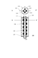
- This figure is a cross-sectional view of the ultraviolet sterilizer which can be conveniently used at the ultraviolet irradiation process of the method concerning one embodiment of the present invention.
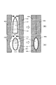
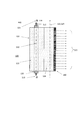
- This figure is the cross-sectional view and longitudinal cross-sectional view of the ultraviolet-ray light emitting module which can be used suitably with the ultraviolet-ray disinfection apparatus shown in FIG.
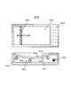
- This figure is a schematic diagram for demonstrating the preferable aspect of the ultraviolet-ray irradiation process of the method concerning one Embodiment of this invention.
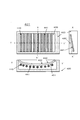
- This figure is a schematic view of an ultraviolet irradiation unit suitably used in the mode shown in FIG.
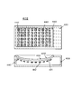
- This figure is a schematic view of another ultraviolet irradiation unit suitably used in the mode shown in FIG.
- This figure is a schematic view of still another ultraviolet irradiation unit suitably used in the mode shown in FIG.
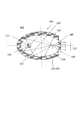
- This figure is a cross-sectional view of the light source (light collecting modularized light source) in the ultraviolet irradiation unit shown in FIG.
- This figure is a side view of the light source (light collecting modularized light source) in the ultraviolet irradiation unit shown in FIG.
- the ultraviolet sterilization method comprises a filling step of filling an object to be disinfected in an ultraviolet ray-permeable container, an ultraviolet irradiation step of irradiating ultraviolet rays from the outside of a container filled with the object to be disinfected by the filling step;
- An ultraviolet sterilization method comprising a sealing step of hermetically sealing a container filled with an object to be disinfected, the method comprising: from the end of the filling step to the end of the sealing step to the end of the ultraviolet irradiation step It is characterized in that it is carried out in between, or that the ultraviolet irradiation step and the sealing step are carried out in the same aseptic environment.
- the object to be sterilized in the present embodiment is not particularly limited as long as it can be filled in a container, but it is transparent to ultraviolet light of 253.7 nm because the effect of the ultraviolet sterilization in the present embodiment is remarkable. It is preferable that it is a fluid to-be-sterilized body having a thickness (optical path length: light transmission length in the sample) of 100% or less and 0.001 mm or more when the ratio is 10%.
- a liquid, paste, jelly or mousse-like object to be sterilized having a thickness of 10 mm or less and 0.001 mm is particularly preferable.
- food including beverages
- cosmetics quasi-drugs or medicines having fluidity.
- examples of the food include liquid food, liquid seasoning, edible oil, liquors, beverages, yogurt, ice cream, jelly and the like.
- examples of the cosmetic include various cosmetic products for skin such as cosmetic solution, cosmetic solution, cream, milky lotion and face cleanser, cosmetic products for finishing such as foundation and cosmetic base, perfumes and eau de cologne.
- quasi-drugs may include nutritional drinks, tooth brushing, hair care products and the like, and pharmaceuticals may include eye drops, various drops, various injections, various ointments and the like.
- the effects of this embodiment are not suitable for pressurized heat sterilization, such as raw milk, fresh juice, fresh sake, raw beer, raw soy sauce, etc. containing active ingredients that are decomposed or denatured by pressurized heating.
- the ultraviolet-ray permeable container used by this embodiment will not be specifically limited if it is a container which consists of ultraviolet-ray permeable materials.
- the UV transmitting container may be made of a UV transmitting material as long as the portion in contact with the to-be-sterilized substance filled when the UV transmitting material is filled, and the whole of the container is always made of the UV transmitting material. There is no need. From the viewpoint of easiness of container manufacture, it is preferable to use a UV-transparent resin as the UV-transparent material.
- the UV-transparent resin is preferably a resin having permeability to deep ultraviolet rays having a wavelength of 200 nm to 300 nm, particularly 220 nm to 280 nm, and such resins include polyethylene, polypropylene, polymethyl terpene and the like.
- Polyolefin resin or polyolefin copolymer resin polytetrafluoroethylene, fluorine resin such as tetrafluoroethylene perfluoroalkyl vinyl ether copolymer, methacrylic resin, epoxy resin, alicyclic polyimide resin, polyamide resin, polyvinyl chloride, A polyvinyl alcohol resin (It is preferable that all do not contain additives, such as an ultraviolet absorber and a plasticizer which absorbs the ultraviolet-ray irradiated at an ultraviolet irradiation process, etc.) etc. can be illustrated. Among these resins, it is preferable to use a polyolefin resin or a polyolefin copolymer resin having high heat sealability.
- UV transmitting resins may be used alone or may be used in combination as in a laminate.
- UV transmittance of resin films "Matsui, T., Shimizu, Y.,” UV, transmittance of plastic films, II “, Research report of Toyo Food Research Institute, Toyo Food Research Institute, 102-111 (1967)” , “Daikin Industries, Ltd. technical Information GX-27e” Neofuren TM film "", http: such as in data //jp.mitsuichem.com/service/functional_polymeric/polymers/tpx/spec.htm have been described.
- the shape of the ultraviolet ray-permeable container is not particularly limited, and may be any of a bag-like container, a box-like container, and a bottle-like container, and may be any other shape.
- the thickness of the container material (the partition that divides the outside of the container from the inside, the thickness of the sheet or film) be thin as long as it has the strength capable of holding the contents.
- the preferable thickness of the container material is 5 ⁇ m or more and 1 mm or less, the more preferable thickness is 10 ⁇ m or more and 500 ⁇ m or less, and the particularly preferable thickness is 20 ⁇ m or more and 300 ⁇ m or less.
- the transmittance of the container material (partitions dividing the outside and the inside, the sheet, or the film) to the irradiated ultraviolet light is preferably 50% or more, more preferably 70% or more, and 75% or more. Is most preferred.
- the container made of an ultraviolet-transparent resin can form an ultraviolet-permeable film made of a heat-sealable resin. It is preferable that it is a flexible bag which makes the ultraviolet-permeable laminated resin film which comprises the said flexible bag or heat-sealable resin layer into a bag.
- an ultraviolet-ray permeable laminated resin film which comprises a heat sealable resin layer what is disclosed by Unexamined-Japanese-Patent No. 2013-534874 can be mentioned, for example.
- a flexible bag formed by forming a UV-transparent film made of a heat-sealable resin or a UV-transparent laminated resin film containing a heat-sealable resin layer is formed.
- the form is not limited as long as it is a flexible bag having an opening for filling the object to be sterilized, and the form is not limited, and a two-way bag, a three-way bag, a gusset bag, a bottom gusset bag, a stand bag, a side seal bag
- Well-known forms, such as a bottom seal bag, are employable. These bags may have spouts or zippers or chucks.
- the filling step is the same as the conventional filling step except that a container made of an ultraviolet light transmitting resin is used, and can be performed using, for example, an automatic pouch filling machine or an automatic bottle filling machine.
- the sealing step is performed by sealing the container in an airtight manner.
- adhesion using a heat seal or an adhesive can be suitably adopted when the container is a bag-like one, and capping can be suitably adopted when the container is a bottle-like one.
- gas replacement processing or degassing processing can also be performed. These treatments can be easily performed using dedicated equipment generally used in so-called vacuum packaging or gas-filled packaging.
- the sealing step is performed after the filling step is completed until the ultraviolet irradiation step (details will be described later) is ended, or the ultraviolet irradiation step and the above are described.
- the sealing step is performed under the same sterile environment.
- to carry out under the same aseptic environment means, for example, an object to be sterilized in a sterility-maintained space such as a room which is fully sterilized and to which positive pressure is supplied with sterilized air.
- the ultraviolet irradiation step and the sealing step are performed without taking out the container filled with.
- the sealing process can also be performed after the ultraviolet irradiation.
- an ultraviolet-ray is irradiated from the exterior of the said container with which the to-be-sterilized body was filled.
- the ultraviolet rays to be irradiated be deep ultraviolet rays having a wavelength of 200 nm to 300 nm, particularly 220 nm to 280 nm.
- an ultraviolet lamp such as a mercury lamp can be used as an ultraviolet light source
- an ultraviolet light emitting diode UV-LED
- UV-LED deep ultraviolet light emitting diodes
- DUV-LEDs deep ultraviolet light emitting diodes which emit ultraviolet light.
- UV-LEDs do not use mercury, have no standby time, consume less power, and have higher durability than mercury lamps.
- the DUV-LED one having a main peak in a wavelength range of 200 nm to 300 nm, particularly in a range of 220 nm to 280 nm, can be suitably used.
- ultraviolet light having a wavelength of 220 nm to 280 nm, the object to be sterilized can be sterilized without generating ozone or the like.
- the method of irradiating ultraviolet light from the outside of the container filled with the object to be sterilized is not particularly limited, but in the case of using an object to be sterilized having a low ultraviolet transmittance, the ultraviolet light of high intensity is irradiated. Is preferred. As described above, in the case of an object to be sterilized consisting of a solution or a suspension, the intensity of the irradiated ultraviolet light is rapidly attenuated as the length in the thickness direction of the object becomes longer (the depth becomes deeper). It does not reach the body to be disinfected.
- the width of the container (the maximum length of the optical axis of the irradiated ultraviolet light crossing the container, for example, W in FIG. 3) is reduced (thinned) or the intensity of the irradiated ultraviolet light is increased.
- the width or the ultraviolet light intensity of the container is controlled, and the irradiance of ultraviolet light at any position of the object to be disinfected filled in the container is 0.01 mW / cm 2 or more, particularly preferably 0. It is preferable to set it to .03 mW / cm 2 or more, and most preferably 0.05 mW / cm 2 or more. The higher the irradiance, the better, and there is no special meaning to set the upper limit, but it is generally 1 W / cm 2 or less.
- the value of the above-mentioned irradiance: 0.01 mW / cm 2 , 0.03 mW / cm 2 or 0.05 mW / cm 2 does not mean that the numerical value itself has a critical meaning, and industrially practical processing It is an index determined from the viewpoint of being able to obtain an effective bactericidal effect in time (ultraviolet irradiation time). For example, in the case of sterilization of E.
- pressure heating sterilization is performed at a center temperature of 120 ° C for 4 minutes or more.
- the irradiance of the ultraviolet rays at the central portion in the container should be 0.01 mW / cm 2 or more. preferably, it is more preferable to make the 0.03 mW / cm 2 or more, and most preferable to be 0.05 mW / cm 2 or more.
- the above (i) and the above-mentioned (i) and the above-mentioned (i) can be obtained by examining the relationship between the optical path length and the irradiance of the transmitted ultraviolet ray in advance according to the following steps
- the irradiance at each position can be easily estimated.
- I 0 is the irradiance of ultraviolet rays before the wavelength lambda incident on the medium
- alpha is a proportionality constant determined in response to the sterilization body
- the wavelength lambda peak (absorption coefficient).
- the peak width of the emission spectrum of the light emitting diode is extremely narrow, so to discuss the optical path length dependence of the irradiance of the transmitted ultraviolet light, only the absorption coefficient ⁇ ( ⁇ peak ) at the emission peak wavelength ⁇ peak of the deep ultraviolet light emitting diode It is enough to think about.
- Expression (1) can be transformed as the following expression (2).
- log I 1 ⁇ L + log I 0 (2)
- a known method such as the least square method can be used.
- the intensity of the ultraviolet light to be irradiated may be controlled, and the thin container can be used
- the container width and / or the ultraviolet intensity may be controlled.
- UV-LEDs Ultraviolet light emitting diodes
- DUV-LEDs deep ultraviolet light emitting diodes
- UV-LEDs have a weak light output as well as a high directivity of emitted ultraviolet light as compared with ultraviolet lamps, so the ultraviolet light irradiation region is narrow turn into. Therefore, it is particularly difficult to control the width of the container, and in the case of using a UV-LED or DUV-LED as a light source, the UV-transparent container has a strong intensity over the entire surface to be irradiated with ultraviolet light. It is necessary to irradiate ultraviolet light.
- a method of irradiating UV light of strong intensity over the entire surface of the UV-transparent container to be irradiated with UV light a method of increasing irradiance using light condensation or a high pressure DC-DC converter or charge pump is used. It is preferable to adopt a method of flowing forward current to increase the light emission output (in this case, pulsed light may be emitted as necessary).
- an ultraviolet-permeable container is an axially-symmetrical hollow body such as a bottle, and deformation (deformation to return to the original shape by removing force or applying recovery force by temporary deformation by applying force) If it is difficult, the following method can be suitably employed.
- a material to be disinfected consisting of a fluid, the periphery of which is made of a material having permeability to ultraviolet light having a sterilizing action, is to flow A flow path and a light source disposed outside the flow path and emitting an ultraviolet light having a sterilizing action, and irradiating the ultraviolet light emitted from the light source to an object to be disinfected circulating in the flow path
- An ultraviolet sterilizing device for sterilizing the light source wherein the light source comprises a plurality of "ultraviolet light emitting elements for emitting ultraviolet light having a sterilizing action", and a light collecting device for condensing the ultraviolet rays emitted from the respective ultraviolet light emitting elements
- the flow path is disposed in place of the flow path of the “ultraviolet sterilizing device according to the present invention”, characterized in that the UV sterilization device is characterized in that Position) to be disinfected Place Hama containers (also referred to as method
- a large number of DUV-LEDs are aligned across the entire inner surface of the cylindrical substrate that can accommodate the container, which faces the container, and a high forward direction using a boost DC-DC converter or charge pump
- a method also referred to as method 2) of applying a current and irradiating ultraviolet light at high output can be suitably employed.
- the container may be a thin (for example, flat plate) container, and the ultraviolet ray may be strengthened as needed.
- the UV-transparent container is a flexible bag
- the bag should be in the form of a thin elliptical cylinder (including one whose thickness gradually decreases in the height direction) or a square cylinder (or flat plate). It is preferable to perform ultraviolet irradiation by the following method (also referred to as method 3).
- the surface of the ultraviolet ray permeable container filled with the body to be disinfected is in proximity to the partition walls in a space between a pair of partition walls arranged to face each other with a gap of a predetermined width. Alternatively, they are disposed in contact with each other, and ultraviolet light is emitted from one or two ultraviolet light emitting surfaces provided on one or both of the facing surfaces of the pair of partition walls. At this time, when only the surface of one of the partition walls is an ultraviolet light emitting surface, it is preferable that the surface of the other partition wall (the surface facing the ultraviolet light emitting surface) be an ultraviolet reflection mirror.
- the area of 50% or more of the surface of the ultraviolet ray permeable container filled with the object to be sterilized is disposed so as to be close to or in contact with the partition wall, and the two opposing surfaces of the pair of partition walls
- a method also referred to as method 3-1 of irradiating ultraviolet light from each of two ultraviolet light emission surfaces provided on both sides, and the ultraviolet light emission surface is the surface of the ultraviolet light transmitting container filled with the object to be sterilized.
- a flexible bag or heat sealability is obtained by forming the ultraviolet ray permeable film, wherein the body to be sterilized is liquid, paste, jelly or mousse, and the ultraviolet ray permeable container is made of a heat sealable resin.
- the flexible bag filled with the body to be sterilized is the front side and / or the back side thereof. It is preferable to adopt a method (also referred to as method 3-3) in which the flexible bag is deformed so as to be thinner by holding the pressure from the side by the ultraviolet light emitting surface so as to reduce the thickness of the flexible bag.
- FIG. 1 is a cross-sectional view of an ultraviolet sterilizer 100 used in method 1.
- the apparatus is basically the same as the apparatus shown in FIG. 4 of Patent Document 4, and the sterilization target is placed at the position where the quartz tube or the sapphire tube constituting the flow path in the apparatus shown in FIG.
- a bottle-shaped UV-permeable container 300 filled with a body 200 is disposed.
- the ultraviolet sterilizer 100 shown in FIG. 1 is arranged such that “a plurality of deep ultraviolet light emitting devices are disposed on the side surface of the cylindrical substrate so that the optical axis of each deep ultraviolet light emitting device passes through the central axis of the substrate.
- a light source comprising an ultraviolet light emitting module 110 in which the deep ultraviolet light is emitted radially with respect to the central axis, and a light collecting device comprising a long oval reflection mirror 120, wherein the long oval reflection mirror 120
- the ultraviolet light emitting module 110 is disposed on the focal axis of the light source, and the “condensed ultraviolet light emitting unit“ 130 ”for condensing and emitting the ultraviolet light emitted radially from the ultraviolet light emitting module 110 is provided.
- the four collected ultraviolet radiation output units 130 are disposed such that the respective collection axes coincide with each other, and the collection axes coincide with the symmetry axis (central axis) of the bottle-shaped ultraviolet ray transmitting container 300.
- the UV permeable container 300 is arranged to
- a plurality of DUV-LEDs 112 are aligned on the surface of the cylindrical substrate 111, and the cooling medium flow channel 113 is provided inside the cylindrical substrate. Is formed.
- the cylindrical substrate 111 on which the DUV-LED 112 is mounted is covered with a cover 116 formed of an ultraviolet light transmissive material such as quartz or sapphire.
- the cover 116 is airtightly or watertightly attached to the cylindrical substrate using a sealing member 117 such as a sealing agent, packing, o-ring, etc., and an inert gas such as nitrogen or a gas such as dry air is enclosed therein. It is done.
- the DUV-LED is disposed in a state where the element is mounted on a submount or housed in a package, and is further disposed so that ultraviolet light is emitted in a certain direction.
- a wire for supplying power to the deep ultraviolet light emitting element from the outside, a circuit for properly operating the DUV-LED, etc. are formed in the submount or the package.
- the supply of power to the circuit is performed via a wire formed on or in the surface of the cylindrical substrate 111.
- a plurality of DUV-LEDs 112 are arranged along the circumferential direction of the substrate such that the optical axis 115 of each DUV-LED 112 passes through the central axis 114 of the substrate 111.
- the deep ultraviolet rays emitted from the DUV-LED are emitted radially with respect to the central axis 114.
- the symmetry axis (central axis) of the ultraviolet ray transmitting container 300 is disposed so as to coincide with the condensing axis of the four collected ultraviolet ray emitting units 130, the rays are emitted radially from the respective ultraviolet light emitting modules 110 All deep ultraviolet rays are collected so as to converge on the symmetry axis (central axis) of the ultraviolet ray transmitting container 300.
- the ultraviolet sterilization device 100 in principle, all the deep ultraviolet rays emitted radially from the ultraviolet light emitting module 110 can be irradiated to the ultraviolet permeable container 300, and in the direction of the ultraviolet transparent container 300 It is also possible to make effective use of ultraviolet light emitted in a direction that does not go (for example, in the opposite direction or in the lateral direction). And as a result, it becomes possible to irradiate high intensity ultraviolet rays.
- FIG. 3 is a schematic view for explaining the method 3-3, where the lower part (A) is a bottom view and the upper part (B) is a front view.
- a liquid, paste, jelly or mousse may be used as the body 210 to be sterilized, and an ultraviolet light permeable film made of a heat sealable resin may be formed as the ultraviolet light permeable container 310.
- a flexible "elliptical bottom stand bag” is used, which is made of a flexible bag or a heat-sealable resin layer and made of an ultraviolet-transparent laminated resin film. Then, first, in the filling step and the sealing step (not shown), the ultraviolet ray transmitting container 310 is filled with the body to be sterilized 210, and sealing is performed.
- the central portion of the space between the ultraviolet irradiation units 400a and 400b which is a pair of partition walls arranged so as to face each other with a gap having a predetermined width, as shown in FIG. .
- the UV irradiation units 400a and 400b automatically move in the direction of the UV transmitting container 310, respectively, and the UV light emitting surfaces 410a and 410b of the UV emitting units clamp the UV transmitting container 310. There is. And it is made to deform so that thickness may become thin and ultraviolet irradiation is performed.
- the UV irradiating units 400a and 400b basically have the same structure except that they are mirror images of each other, and the light emitting surfaces 410a and 410b correspond to the shape of the UV transmitting container 310 which is pressed. It has a shape.
- the light emitting surfaces 410a and 410b of the ultraviolet irradiation unit used in FIG. 3 are concave curved surfaces corresponding to the shape of a stand bag (ultraviolet light permeable container 310) having an elliptical bottom surface.
- the shape of the light emitting surface may be appropriately changed in accordance with the shape of the ultraviolet ray transmitting container, and for example, when the ultraviolet ray transmitting container is a flat bag (a plate-like ultraviolet ray transmitting container), it is flat.
- the UV irradiation units 401, 402 and 403 preferably used in the method shown in FIG. 3 are shown in FIGS.
- Each of these UV irradiation units has a housing 420 having an opening, an inner surface 431 and an outer surface 432 opposite to the inner surface, and the inner surface of the housing is closed so as to close the opening of the housing.
- It has an ultraviolet transmitting window 430 for transmitting ultraviolet light and an ultraviolet light source 440, which are disposed toward the inside, and are arranged opposite to the outer surface 432 of the ultraviolet transmitting window (filled inside the ultraviolet transmitting container
- the product to be sterilized is irradiated with ultraviolet light to perform sterilization. Therefore, the outer side surface 432 of the ultraviolet ray transmission window 430 becomes the light emitting surface 410a (410b) in FIG.
- the material forming the housing 420 is not particularly limited as long as it does not transmit ultraviolet light, and for example, metal, resin, etc. can be adopted. However, it is preferable that the inner surface of the housing 420, more specifically, the surface of the portion visible as viewed from the outside of the ultraviolet transmission window 430 be made of an ultraviolet reflective material.
- UV reflective material As an example of the UV reflective material that can be suitably used in the present embodiment, chromium (UV reflectance: about 50%), platinum (UV reflectance: about 50%), rhodium (UV reflectance: about 65%), sulfuric acid Barium (UV reflectance: about 95%), magnesium carbonate (UV reflectance: about 75%), calcium carbonate (UV reflectance: about 75%), magnesium oxide (UV reflectance: about 90%), aluminum (UV light Reflectivity: about 90%) and the like.
- rhodium, platinum or aluminum it is particularly preferable to use rhodium, platinum or aluminum as the ultraviolet reflective material because it can be made a surface with high reflectance by surface treatment such as plating or vapor deposition.
- ultraviolet light such as quartz, sapphire, or polytetrafluoroethylene film is used from the viewpoint of preventing a decrease in reflectance due to oxidation or damage on the surface. It is preferable to coat the surface of the UV reflective material with a transmissive material.
- the UV transmitting window 430 has an inner side surface 431 and an outer side surface 432 opposite to the inner side, and is provided to close the opening of the housing 420 so that the inner side faces the inside of the housing 420.
- the ultraviolet rays emitted from 440 pass through the ultraviolet ray transmitting window 430 and the partition (or sheet or film) of the ultraviolet ray transmitting container 310 and irradiate the object to be sterilized 210.
- transmission window 430 sapphire, quartz etc. are preferably employable, for example.
- the UV transmitting window 430 can be suitably configured by a molded body made of a UV transmitting resin or a flexible sheet (or film).
- Examples of such an ultraviolet light transmitting resin include polytetrafluoroethylene, polyethylene, polypropylene, methacrylic resin, epoxy resin, alicyclic polyimide resin, polyamide resin, polyvinyl chloride, polyvinyl alcohol resin, etc. Preferred are those which do not contain such additives as UV absorbers and plasticizers which absorb.
- an ultraviolet-ray transmission window looks like a housing. It is preferable that it is attached by a detachable structure.
- the UV transmission window 430 has a concave curved surface inclined corresponding to the shape of the stand bag (UV transparent container 310). There is.
- the light source 440 differs in the ultraviolet irradiation units 401, 402, and 403, and the ultraviolet irradiation unit 401 shown in FIG. 4 uses a plurality of ultraviolet lamps 441 (linear light sources) as light sources.
- the ultraviolet lamps 441 are arranged at predetermined intervals along the inner side surface 431 of the ultraviolet transmission window 430, and an ultraviolet reflection mirror (not shown) is disposed behind the ultraviolet lamps 441. The ultraviolet light thus reflected is reflected by the mirror and travels toward the ultraviolet lamp 441 from the gap between the lamps.
- the ultraviolet irradiation unit 402 shown in FIG. 5 uses a plurality of DUV-LEDs 442 (point light sources) as light sources.
- the plurality of DUV-LEDs 442 face the inner side surface 431 of the UV transmission window 430 in a form mounted on a substrate (not shown) mainly made of a metal or ceramic having high thermal conductivity such as copper and aluminum. It is aligned as you want.
- DUV-LED 442 is typically packaged or modularized and emits more directional light such as parallel light, but with a certain degree of output angle so that the distribution of light intensity is more uniform Preferably, light is emitted radially.
- the number of DUV-LEDs 442 may be sufficient so that the emitted ultraviolet light irradiates the entire surface of the inner side surface 431 of the ultraviolet transmission window 430.
- high output can be achieved by flowing high forward current using a boost DC-DC converter or charge pump.
- the ultraviolet light emitting module 110 shown in FIG. 2 is incorporated as a light source, and the ultraviolet rays emitted radially to the central axis 114 of the ultraviolet light emitting module 110 are collected
- the condensing modular light source 443 is described as an ultraviolet light emitting device in Japanese Patent No. 5591305, the contents of which are incorporated herein by reference.
- FIG. 7 and 8 show a cross-sectional view and a side view of the light collecting modular light source 443 having the rod-like light source 110.
- the light collecting modularized light source 443 is an output side case 125 whose output side is a reflection mirror 120 whose inner surface is a long elliptical reflection mirror, and a light collection side reflection mirror 123 whose inner surface is a long oval reflection mirror And a main body 150 consisting of a collimating optical system 140 disposed in the deep ultraviolet light emission opening 130, and a light collecting side housing 126 in which the deep ultraviolet light emission opening 130 is formed.
- the rod-like light source 110 is disposed inside.
- the emission side casing 125 and the light collection side casing 126 be detachable from each other or be openable / closable using a hinge or the like.
- the cover (not shown) for preventing that an ultraviolet-ray leaks outside is provided in the up-and-down both-ends opening part in FIG.7 and FIG.8 of the main body 150. As shown in FIG.
- the output side reflection mirror 120 and the light collection side reflection mirror 123 are substantially oblong reflecting mirrors having the same shape, in the main body 150, the output side housing 125 and the light collection side are collected.
- the shape of the internal space formed by coupling with the side housing 126 is an elliptical cross section in which two axes of the focal axis 121 of the output side reflection mirror and the focusing axis 122 of the output side reflection mirror are focal axes ( However, a portion corresponding to the opening 130 is missing).
- the surfaces of the emission side reflection mirror 120 and the collection side reflection mirror 123 are made of a material having a large reflectance to deep ultraviolet light, for example, platinum group metals such as Ru, Rh, Pd, Os, Ir, Pt, Al, Ag, Ti, It is preferable to be composed of an alloy containing at least one of these metals, or magnesium oxide, and formed of Al, a platinum group metal or an alloy containing a platinum group metal, or magnesium oxide because the reflectance is particularly high. Is particularly preferred.
- the light collecting side reflection mirror 123 and the light collecting side housing 126 are provided with a deep ultraviolet light emission opening 130 in the form of a slit, and in the opening 130 a parallel or substantially parallel light flux of collected ultraviolet light
- the collimating optical system 140 which converts into.
- the collimating optical system 140 is preferably made of a highly ultraviolet light transmitting material such as synthetic or natural quartz, sapphire, or an ultraviolet light transmitting resin. It is preferable that the collimating optical system 140 be detachably attached to the deep ultraviolet light emitting opening 130.
- the rod-like light source 110 is arranged such that its central axis 114 coincides with the focal axis 121 of the output side reflection mirror. Since the rod-like light source 110 is disposed at such a position, the deep ultraviolet light radially emitted from the rod-like light source 110 is reflected by the emission side reflection mirror 120 and the collection side reflection mirror 123 to be Focused deep ultraviolet light collected to converge on the focal axis 124 (i.e., the collection axis 122 of the emission side reflection mirror) is emitted toward the inner side surface 431 of the ultraviolet light transmission window 430.
- the focal axis 124 i.e., the collection axis 122 of the emission side reflection mirror
- all the deep ultraviolet light emitted radially from the rod-like light source 110 can be collected on the focal axis 124 of the light collecting side reflection mirror 123. It is also possible to effectively utilize ultraviolet light emitted in a direction (for example, the opposite direction or in the lateral direction) not directed toward the light emitting opening 130. That is, in the rod-like light source 110, it is not necessary to arrange all the deep ultraviolet LEDs 112, 112, ... on the same plane so that the optical axis 115 is directed toward the deep ultraviolet light emitting opening 130; It also becomes possible to arrange it facing.
- the number of ultraviolet light emitting elements arranged per unit space can be significantly increased, and in the light collecting modular light source 443 it is possible to emit ultraviolet light of stronger intensity. Further, it is not necessary to use a large aperture field lens in the light collecting modular light source 443. Further, in the light collecting modularized light source 443, the ultraviolet light is emitted as a band-like light flux, and the irradiation area can irradiate the ultraviolet light of uniform intensity not to a narrow spot but to a rectangular area having a long side.
- the light collecting modularized light source 443 is disposed in the housing 420 so as to emit the band-like light flux toward the inner side surface 431 of the ultraviolet light transmitting window 430. Further, an electric motor 450 and a pair of guide rails 460 are disposed in the housing 420, and the light collecting modular light source 443 is held by the guide rails 460 and driven by the electric motor 450 so as to be on the guide rails. Reciprocate (slide) in the direction of the arrow in the lower part of FIG.
- a mechanism (not shown) for converting the rotational drive force of the electric motor 450 into a drive force for linear movement along the guide rail 460 known mechanisms such as a rack and pinion mechanism, a crank mechanism, a cam mechanism, and a belt mechanism
- a rotational motion-linear motion conversion mechanism can be adopted without particular limitation.
- Ultraviolet light is scanned by the reciprocating modularization light source 443 by such reciprocating movement (slide), and the entire surface of the inner side surface 431 of the ultraviolet light transmission window 430 can be irradiated with ultraviolet light.
- the ultraviolet irradiation units 401 to 403 may also have a heat seal unit for sealing the ultraviolet permeable container 310.
- the heat seal unit has, for example, a heater disposed in the housing and a pinching portion for pinching the sealing portion of the ultraviolet light permeable container, and the body to be sterilized is heated by heating the pinching portion with the heater.
- the sealing step can be carried out before, during or after the irradiation of ultraviolet light.
- the ultraviolet ray transmitting container may have a form in which a plurality of the ultraviolet ray transmitting containers are connected.
- the plurality of UV irradiation units are also connected to each other, whereby the objects to be disinfected in the plurality of UV permeable containers can be sterilized simultaneously.
- an ultraviolet irradiation unit about a case where an ultraviolet-ray permeable container is a stand bag which has an elliptical bottom as an example
- a condensing ultraviolet radiation unit is not limited to this.
- the shape of the light emitting surface may be appropriately changed in accordance with the shape of the ultraviolet ray permeable container, and for example, when the ultraviolet ray permeable container is a flat bag (plate-shaped ultraviolet ray permeable container) It is assumed.
- a surface light emitting device as disclosed in Patent Document 5 can be used as an ultraviolet irradiation unit.
- a container-packed article obtained by the ultraviolet sterilization method of the present embodiment, in which the UV-sterilized object is sealed in the ultraviolet-permeable container It is possible to distribute it as a product as it is, but it is possible to prevent deterioration of the body to be disinfected or deterioration of the container due to ultraviolet rays from the natural world during storage or in the distribution process.
- the method further comprises an ultraviolet shielding step of performing an ultraviolet shielding process on the outer surface of the ultraviolet transmitting container sealed in the sealing step.
- an ultraviolet ray impermeable material may be coated on the ultraviolet transparent portion of the container.
- the coating method include a method of printing using an ultraviolet opaque ink, a method of surface coating with an ultraviolet opaque coating agent, and a method of laminating (laminating) an ultraviolet opaque film.
- the UV sterilization method of the present embodiment is suitably applied to a method for producing a container-packed article in which a UV-sterilized, flowable food, a cosmetic, a quasi-drug or a medicine is enclosed in a container. it can.
- Ultraviolet sterilization device 110 Ultraviolet light emitting module 111 ⁇ Cylindrical substrate 112, 442 ⁇ Deep ultraviolet light emitting element (DUV-LED) 113 ... a flow path for a cooling medium 114 ... a central axis of a cylindrical substrate 115 ... an optical axis of a deep ultraviolet light emitting element 116 ... a cover 117 ... a sealing member 118 ...
- DUV-LED Deep ultraviolet light emitting element
- a cooling medium 120 ⁇ ⁇ ⁇ Emission side reflection mirror 121 consisting of a long elliptical reflection mirror ⁇ ⁇ ⁇ Focal axis of the emission side reflection mirror 122 ⁇ ⁇ ⁇ Condensing axis of the emission side reflection mirror 123 ⁇ ⁇ ⁇
- a collection side reflection mirror 124 consisting of a long ellipse reflection mirror ... Focal axis 125 of collecting side reflection mirror ...
- Output side case 126 ... Collection side case 130 ...
- Collection ultraviolet ray emitting unit (combination of 110 and 120) 140: Collimation optical system 150: Main body 200, 210: Object to be sterilized 300, 310: Ultraviolet light permeable container 400a, 400b, 401, 402, 403: Ultraviolet irradiation unit 420 Casing 430 ⁇ UV transmission window 431 ⁇ inner surface 432 ⁇ outer surface 440 ⁇ light source 441 ⁇ ultraviolet lamp 443 ⁇ light condensing modular light source 450 ⁇ electric motor 460 ⁇ Guide rail
Landscapes
- Health & Medical Sciences (AREA)
- Engineering & Computer Science (AREA)
- General Health & Medical Sciences (AREA)
- Life Sciences & Earth Sciences (AREA)
- Mechanical Engineering (AREA)
- Toxicology (AREA)
- Animal Behavior & Ethology (AREA)
- Epidemiology (AREA)
- Public Health (AREA)
- Veterinary Medicine (AREA)
- Polymers & Plastics (AREA)
- Food Science & Technology (AREA)
- Chemical & Material Sciences (AREA)
- Zoology (AREA)
- Wood Science & Technology (AREA)
- Apparatus For Disinfection Or Sterilisation (AREA)
- Food Preservation Except Freezing, Refrigeration, And Drying (AREA)
Abstract
La présente invention concerne un procédé de stérilisation avec lequel une stérilisation aux ultraviolets extrêmement fiable est possible, même pour, par exemple, un article à stériliser ayant une faible transmissivité des ultraviolets, tel que des aliments et des boissons, avec lequel il est possible d'éliminer sensiblement le recours à une procédure de nettoyage pour le matériau de fenêtre de transmission des ultraviolets dans un dispositif d'irradiation aux ultraviolets, et qui expose à un risque de recontamination négligeable. L'invention concerne un procédé de stérilisation aux ultraviolets dans lequel, lors de la réalisation d'une stérilisation d'un article à stériliser, par exemple, un récipient à transmission des ultraviolets contenant un article à stériliser, tel qu'une poche flexible fabriquée à partir d'un film à transmission des ultraviolets comprenant une résine thermoscellable, l'article ayant été placé dans le récipient à transmission des ultraviolets, et le récipient ensuite irradié avec des rayons ultraviolets provenant de l'extérieur, le récipient emballant l'article à stériliser est soit scellé de façon étanche à l'air entre le moment de l'emballage et la fin de l'irradiation aux ultraviolets, soit les opérations d'irradiation aux ultraviolets et de scellement sont effectuées dans le même environnement stérile.
Priority Applications (2)
| Application Number | Priority Date | Filing Date | Title |
|---|---|---|---|
| US15/575,262 US20180132508A1 (en) | 2015-05-19 | 2016-05-16 | Ultraviolet Sterilization Method, Method of Manufacturing Container-Packaged Product, and Ultraviolet Sterilization Apparatus |
| EP16796461.8A EP3299305A4 (fr) | 2015-05-19 | 2016-05-16 | Procédé de stérilisation aux ultraviolets, procédé pour fabriquer un produit emballé dans un récipient, et dispositif de stérilisation aux ultraviolets |
Applications Claiming Priority (2)
| Application Number | Priority Date | Filing Date | Title |
|---|---|---|---|
| JP2015-101459 | 2015-05-19 | ||
| JP2015101459A JP6055513B2 (ja) | 2015-05-19 | 2015-05-19 | 紫外線殺菌方法 |
Publications (1)
| Publication Number | Publication Date |
|---|---|
| WO2016186068A1 true WO2016186068A1 (fr) | 2016-11-24 |
Family
ID=57319924
Family Applications (1)
| Application Number | Title | Priority Date | Filing Date |
|---|---|---|---|
| PCT/JP2016/064437 Ceased WO2016186068A1 (fr) | 2015-05-19 | 2016-05-16 | Procédé de stérilisation aux ultraviolets, procédé pour fabriquer un produit emballé dans un récipient, et dispositif de stérilisation aux ultraviolets |
Country Status (5)
| Country | Link |
|---|---|
| US (1) | US20180132508A1 (fr) |
| EP (1) | EP3299305A4 (fr) |
| JP (1) | JP6055513B2 (fr) |
| TW (1) | TW201705991A (fr) |
| WO (1) | WO2016186068A1 (fr) |
Cited By (2)
| Publication number | Priority date | Publication date | Assignee | Title |
|---|---|---|---|---|
| WO2018026008A1 (fr) * | 2016-08-05 | 2018-02-08 | 株式会社トクヤマ | Procédé de stérilisation par rayons ultraviolets et dispositif de stérilisation par rayons ultraviolets |
| WO2018216709A1 (fr) | 2017-05-26 | 2018-11-29 | ウシオ電機株式会社 | Procédé de stérilisation et dispositif de stérilisation |
Families Citing this family (8)
| Publication number | Priority date | Publication date | Assignee | Title |
|---|---|---|---|---|
| DE102017123110A1 (de) * | 2017-10-05 | 2019-04-11 | Lar Process Analysers Ag | Analysevorrichtung |
| JP7011930B2 (ja) * | 2017-12-07 | 2022-01-27 | スタンレー電気株式会社 | 流体殺菌装置 |
| JP2020010830A (ja) * | 2018-07-18 | 2020-01-23 | 旭化成株式会社 | 流体殺菌モジュール |
| JP6896919B1 (ja) * | 2020-08-03 | 2021-06-30 | 株式会社クォークテクノロジー | 殺菌ランプ |
| JP6948605B1 (ja) | 2020-08-05 | 2021-10-13 | ウシオ電機株式会社 | 菌又はウイルスの不活化方法、菌又はウイルスの不活化装置 |
| JP2024506193A (ja) * | 2021-02-15 | 2024-02-09 | ジー.デー ソチエタ ペル アツィオニ | タバコ産業の物品を包装するための機械および方法 |
| US20220413310A1 (en) * | 2021-06-29 | 2022-12-29 | Ronald Scott Frazier | Method and Technique for the Focusing of UVC Light Energy to a Focused Energy Beam |
| WO2023058376A1 (fr) * | 2021-10-05 | 2023-04-13 | 株式会社Reiz | Circulateur de nettoyage de fluide |
Citations (6)
| Publication number | Priority date | Publication date | Assignee | Title |
|---|---|---|---|---|
| JP2000511497A (ja) * | 1996-05-22 | 2000-09-05 | ピュアパルス テクノロジーズ インコーポレイテッド | パッケージ及びその内容物のパルス光滅菌におけるパラメータ制御 |
| JP2002068202A (ja) * | 2000-08-29 | 2002-03-08 | Toyo Seikan Kaisha Ltd | 紫外線遮断性ボトル |
| JP2005052294A (ja) * | 2003-08-01 | 2005-03-03 | Iwasaki Electric Co Ltd | 光パルス照射装置とその照射器 |
| JP2007126189A (ja) * | 2005-11-04 | 2007-05-24 | Iwasaki Electric Co Ltd | 光殺菌システムとそれに用いる閃光照射装置 |
| GB2457057A (en) * | 2008-01-31 | 2009-08-05 | Gb Environmental Ltd | Sterilisation of food contained within a sealed receptacle |
| JP2014516013A (ja) * | 2011-05-09 | 2014-07-07 | オゾニカ リミテッド | 包装された物品の殺菌 |
Family Cites Families (8)
| Publication number | Priority date | Publication date | Assignee | Title |
|---|---|---|---|---|
| US8754385B1 (en) * | 1999-06-01 | 2014-06-17 | Jose Gutman | Advanced system and method for ozone containing packaging for sanitizing application |
| BR0106707A (pt) * | 2000-05-30 | 2002-07-23 | Hoshin Kagaku Sangyosho Kk | Método para esterilizar fungos e/ou bactérias em um estado de esporo, e, esterilizador contra fungos e/ou bactérias em um estado de esporo |
| US7875247B2 (en) * | 2002-11-27 | 2011-01-25 | Novatron, Inc. | UV flux multiplication system for sterilizing air, medical devices and other materials |
| CA2559713A1 (fr) * | 2004-02-11 | 2005-08-25 | Barry Ressler | Systeme et procede de sterilisation de produits au moyen d'une source de lumiere ultraviolette |
| JP3997251B1 (ja) * | 2006-04-13 | 2007-10-24 | 有限会社水戸菜園 | 包装体 |
| EP2008669A1 (fr) * | 2007-06-22 | 2008-12-31 | Maco Pharma S.A. | Appareil d'irradiation pour rendre inactif les pathogènes et/ou leucocytes dans un liquide biologique et processus correspondant |
| CA2777014A1 (fr) * | 2009-10-16 | 2011-04-21 | Hospira, Inc. | Systeme de sterilisation par ultraviolets |
| US20120315184A1 (en) * | 2011-05-06 | 2012-12-13 | Novatron, Inc. | Methods and apparatus for diffuse reflective uv cavity air treatment |
-
2015
- 2015-05-19 JP JP2015101459A patent/JP6055513B2/ja not_active Expired - Fee Related
-
2016
- 2016-05-16 US US15/575,262 patent/US20180132508A1/en not_active Abandoned
- 2016-05-16 EP EP16796461.8A patent/EP3299305A4/fr not_active Withdrawn
- 2016-05-16 WO PCT/JP2016/064437 patent/WO2016186068A1/fr not_active Ceased
- 2016-05-18 TW TW105115346A patent/TW201705991A/zh unknown
Patent Citations (6)
| Publication number | Priority date | Publication date | Assignee | Title |
|---|---|---|---|---|
| JP2000511497A (ja) * | 1996-05-22 | 2000-09-05 | ピュアパルス テクノロジーズ インコーポレイテッド | パッケージ及びその内容物のパルス光滅菌におけるパラメータ制御 |
| JP2002068202A (ja) * | 2000-08-29 | 2002-03-08 | Toyo Seikan Kaisha Ltd | 紫外線遮断性ボトル |
| JP2005052294A (ja) * | 2003-08-01 | 2005-03-03 | Iwasaki Electric Co Ltd | 光パルス照射装置とその照射器 |
| JP2007126189A (ja) * | 2005-11-04 | 2007-05-24 | Iwasaki Electric Co Ltd | 光殺菌システムとそれに用いる閃光照射装置 |
| GB2457057A (en) * | 2008-01-31 | 2009-08-05 | Gb Environmental Ltd | Sterilisation of food contained within a sealed receptacle |
| JP2014516013A (ja) * | 2011-05-09 | 2014-07-07 | オゾニカ リミテッド | 包装された物品の殺菌 |
Non-Patent Citations (1)
| Title |
|---|
| See also references of EP3299305A4 * |
Cited By (3)
| Publication number | Priority date | Publication date | Assignee | Title |
|---|---|---|---|---|
| WO2018026008A1 (fr) * | 2016-08-05 | 2018-02-08 | 株式会社トクヤマ | Procédé de stérilisation par rayons ultraviolets et dispositif de stérilisation par rayons ultraviolets |
| WO2018216709A1 (fr) | 2017-05-26 | 2018-11-29 | ウシオ電機株式会社 | Procédé de stérilisation et dispositif de stérilisation |
| KR20190141214A (ko) | 2017-05-26 | 2019-12-23 | 우시오덴키 가부시키가이샤 | 살균 방법, 살균 장치 |
Also Published As
| Publication number | Publication date |
|---|---|
| US20180132508A1 (en) | 2018-05-17 |
| JP2016216078A (ja) | 2016-12-22 |
| TW201705991A (zh) | 2017-02-16 |
| EP3299305A1 (fr) | 2018-03-28 |
| EP3299305A4 (fr) | 2019-01-02 |
| JP6055513B2 (ja) | 2016-12-27 |
Similar Documents
| Publication | Publication Date | Title |
|---|---|---|
| JP6055513B2 (ja) | 紫外線殺菌方法 | |
| US8088289B2 (en) | Method and device for affecting a chemical or mechanical property of a target site | |
| AU710860B2 (en) | Parametric control in pulsed light sterilization of packages and their contents | |
| WO2018026008A1 (fr) | Procédé de stérilisation par rayons ultraviolets et dispositif de stérilisation par rayons ultraviolets | |
| US7683344B2 (en) | In-line treatment of liquids and gases by light irradiation | |
| US6566659B1 (en) | Parametric control in pulsed light sterilization | |
| US7038219B2 (en) | Sterilization of packages and their contents using light | |
| CA2437474A1 (fr) | Desinfection au travers d'un emballage | |
| AU2002222465A1 (en) | Oxidation of dangerous chemical and biological substances | |
| JP2014233712A (ja) | 紫外線殺菌装置 | |
| US9889217B2 (en) | Device and method for the decontamination of hollow objects such as container caps using UV radiations | |
| JP2018102635A (ja) | 殺菌方法及び殺菌装置 | |
| JP4590805B2 (ja) | スパウト付パウチへの無菌充填方法 | |
| JP6405348B2 (ja) | 紫外線殺菌方法 | |
| WO2018051784A1 (fr) | Procédé et dispositif de fabrication d'article ensaché | |
| JP2018104031A (ja) | 容器の殺菌方法及び容器の殺菌装置 | |
| JP4046516B2 (ja) | 空気コンベヤ型容器殺菌装置 | |
| CN209136313U (zh) | 具有紫外杀菌功能的保温瓶 | |
| JP2007126189A (ja) | 光殺菌システムとそれに用いる閃光照射装置 | |
| JP2003072719A (ja) | 無菌充填方法および容器の殺菌方法 | |
| KR20130135589A (ko) | 식품 살균 장치 | |
| NO168622B (no) | Fremgangsmaate og apparat for aseptisk emballering av matvarer |
Legal Events
| Date | Code | Title | Description |
|---|---|---|---|
| 121 | Ep: the epo has been informed by wipo that ep was designated in this application |
Ref document number: 16796461 Country of ref document: EP Kind code of ref document: A1 |
|
| WWE | Wipo information: entry into national phase |
Ref document number: 15575262 Country of ref document: US |
|
| NENP | Non-entry into the national phase |
Ref country code: DE |