WO2016189691A1 - Endoscope et module de transmission optique - Google Patents
Endoscope et module de transmission optique Download PDFInfo
- Publication number
- WO2016189691A1 WO2016189691A1 PCT/JP2015/065232 JP2015065232W WO2016189691A1 WO 2016189691 A1 WO2016189691 A1 WO 2016189691A1 JP 2015065232 W JP2015065232 W JP 2015065232W WO 2016189691 A1 WO2016189691 A1 WO 2016189691A1
- Authority
- WO
- WIPO (PCT)
- Prior art keywords
- optical
- transmission module
- intermediate member
- optical fiber
- hole
- Prior art date
- Legal status (The legal status is an assumption and is not a legal conclusion. Google has not performed a legal analysis and makes no representation as to the accuracy of the status listed.)
- Ceased
Links
Images


Classifications
-
- A—HUMAN NECESSITIES
- A61—MEDICAL OR VETERINARY SCIENCE; HYGIENE
- A61B—DIAGNOSIS; SURGERY; IDENTIFICATION
- A61B1/00—Instruments for performing medical examinations of the interior of cavities or tubes of the body by visual or photographical inspection, e.g. endoscopes; Illuminating arrangements therefor
- A61B1/00002—Operational features of endoscopes
- A61B1/00011—Operational features of endoscopes characterised by signal transmission
- A61B1/00013—Operational features of endoscopes characterised by signal transmission using optical means
-
- A—HUMAN NECESSITIES
- A61—MEDICAL OR VETERINARY SCIENCE; HYGIENE
- A61B—DIAGNOSIS; SURGERY; IDENTIFICATION
- A61B1/00—Instruments for performing medical examinations of the interior of cavities or tubes of the body by visual or photographical inspection, e.g. endoscopes; Illuminating arrangements therefor
- A61B1/00002—Operational features of endoscopes
- A61B1/00004—Operational features of endoscopes characterised by electronic signal processing
-
- A—HUMAN NECESSITIES
- A61—MEDICAL OR VETERINARY SCIENCE; HYGIENE
- A61B—DIAGNOSIS; SURGERY; IDENTIFICATION
- A61B1/00—Instruments for performing medical examinations of the interior of cavities or tubes of the body by visual or photographical inspection, e.g. endoscopes; Illuminating arrangements therefor
- A61B1/00163—Optical arrangements
- A61B1/00165—Optical arrangements with light-conductive means, e.g. fibre optics
- A61B1/0017—Details of single optical fibres, e.g. material or cladding
-
- A—HUMAN NECESSITIES
- A61—MEDICAL OR VETERINARY SCIENCE; HYGIENE
- A61B—DIAGNOSIS; SURGERY; IDENTIFICATION
- A61B1/00—Instruments for performing medical examinations of the interior of cavities or tubes of the body by visual or photographical inspection, e.g. endoscopes; Illuminating arrangements therefor
- A61B1/04—Instruments for performing medical examinations of the interior of cavities or tubes of the body by visual or photographical inspection, e.g. endoscopes; Illuminating arrangements therefor combined with photographic or television appliances
- A61B1/05—Instruments for performing medical examinations of the interior of cavities or tubes of the body by visual or photographical inspection, e.g. endoscopes; Illuminating arrangements therefor combined with photographic or television appliances characterised by the image sensor, e.g. camera, being in the distal end portion
- A61B1/051—Details of CCD assembly
-
- G—PHYSICS
- G02—OPTICS
- G02B—OPTICAL ELEMENTS, SYSTEMS OR APPARATUS
- G02B23/00—Telescopes, e.g. binoculars; Periscopes; Instruments for viewing the inside of hollow bodies; Viewfinders; Optical aiming or sighting devices
- G02B23/24—Instruments or systems for viewing the inside of hollow bodies, e.g. fibrescopes
- G02B23/26—Instruments or systems for viewing the inside of hollow bodies, e.g. fibrescopes using light guides
-
- H—ELECTRICITY
- H04—ELECTRIC COMMUNICATION TECHNIQUE
- H04N—PICTORIAL COMMUNICATION, e.g. TELEVISION
- H04N23/00—Cameras or camera modules comprising electronic image sensors; Control thereof
- H04N23/50—Constructional details
- H04N23/555—Constructional details for picking-up images in sites, inaccessible due to their dimensions or hazardous conditions, e.g. endoscopes or borescopes
-
- H—ELECTRICITY
- H04—ELECTRIC COMMUNICATION TECHNIQUE
- H04N—PICTORIAL COMMUNICATION, e.g. TELEVISION
- H04N23/00—Cameras or camera modules comprising electronic image sensors; Control thereof
- H04N23/56—Cameras or camera modules comprising electronic image sensors; Control thereof provided with illuminating means
Definitions
- the present invention has an optical fiber for transmitting an optical signal, an optical element, a holding member having a through hole into which the optical fiber is inserted, and a hole serving as an optical path for the optical signal on the first main surface.
- the present invention relates to an optical transmission module including a wiring board to which the holding member is bonded and the optical element is mounted on a second main surface, and an endoscope having the optical transmission module at a distal end portion of an insertion portion.
- the endoscope has an image sensor such as a CCD at the distal end of an elongated flexible insertion portion.
- an imaging device having a high pixel number for an endoscope has been studied.
- the amount of signal transmitted from the image sensor to the signal processing device (processor) increases. Therefore, instead of electric signal transmission through metal wiring by electric signals, thin signals by optical signals are used.
- Optical signal transmission via an optical fiber is preferred.
- an E / O optical transmission module electric-optical converter
- O / E optical transmission module optical-electrical converter
- the optical transmission module In an optical transmission module, accurate positioning and fixing are important in order to efficiently optically couple an optical element and an optical fiber that transmits an optical signal.
- the optical transmission module has a holding member (ferrule) having a through hole (through hole) disposed in the wiring board on which the optical element is mounted. ) Is used. By inserting the optical fiber into the through hole of the holding member, the horizontal direction between the optical element and the optical fiber can be easily positioned. In order to accurately position, the diameter of the through hole is set slightly larger than the outer diameter of the optical fiber.
- the hole of the wiring board on which the optical element is mounted is provided. It is disclosed that the optical fiber is formed in a tapered shape and the tip surface of the optical fiber is brought into contact with the hole.
- the sealing resin spreads to the light emitting portion of the optical element, and the amount of light guided to the optical fiber is reduced.
- the coupling efficiency between the optical element and the optical element may be reduced.
- An embodiment of the present invention aims to provide an optical transmission module that has a high coupling efficiency between an optical fiber and an optical element and that can be easily manufactured, and an endoscope that has the optical transmission module at the distal end of an insertion portion. .
- An endoscope includes an insertion portion having a light transmission module at a distal end portion where an imaging element is disposed, and an operation portion extended to a proximal end portion side of the insertion portion.
- the optical transmission module includes a core part that transmits an optical signal, and a cladding part that covers an outer peripheral surface of the core part, and an optical fiber that passes through the insertion part, and emits the optical signal or
- An optical element in which an optical element portion on which an optical signal is incident and an external electrode are arranged on the front surface, a holding member having a through hole into which the optical fiber is inserted, and an optical path of the optical signal A wiring board having a hole, the holding member being bonded to the first main surface and the bonding electrode disposed on the second main surface and the external electrode of the optical element being bonded; A sealing resin that seals the joint between the electrode and the joining electrode,
- the optical fiber further includes an intermediate member having the same configuration as the optical fiber, wherein the upper surface is in contact with the front end surface of
- An optical transmission module is an optical element in which an optical fiber that transmits an optical signal, an optical element portion that emits the optical signal or that receives the optical signal, and an external electrode are disposed on the front surface. And a holding member having a through hole into which the optical fiber is inserted and a hole serving as an optical path for the optical signal, and the holding member is bonded to the first main surface and disposed on the second main surface.
- a wiring board in which the bonded electrode and the external electrode of the optical element are bonded; and a sealing resin that seals a bonded portion between the external electrode and the bonded electrode; further includes an intermediate member in contact with the front end surface of the optical fiber and a lower surface in contact with the optical element portion of the optical element.
- an optical transmission module that has a high coupling efficiency between an optical fiber and an optical element and that can be easily manufactured, and an endoscope that has the optical transmission module at the distal end of the insertion portion.
- optical transmission module of 2nd Embodiment It is a fragmentary sectional view of the optical transmission module of a 2nd embodiment. It is a fragmentary sectional view of the optical transmission module of the modification of a 2nd embodiment. It is a fragmentary sectional view of the optical transmission module of the modification of a 2nd embodiment. It is sectional drawing of the optical transmission module of 3rd Embodiment. It is sectional drawing for demonstrating the manufacturing method of the optical transmission module of 3rd Embodiment. It is sectional drawing for demonstrating the manufacturing method of the optical transmission module of 3rd Embodiment. It is sectional drawing of the optical transmission module of 4th Embodiment. It is sectional drawing of the optical transmission module of 5th Embodiment.
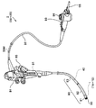
- the endoscope 2 includes an insertion portion 80, an operation portion 84 disposed on the proximal end side of the insertion portion 80, and a universal cord extending from the operation portion 84. 92 and a connector 93 disposed on the base end side of the universal cord 92.
- the insertion portion 80 includes a hard tip portion 81, a bending portion 82 for changing the direction of the tip portion 81, and an elongated flexible soft portion 83 connected in order.
- the distal end portion 81 includes an imaging optical unit 90L, an imaging element 90, and an optical transmission module 1 that is an E / O module that converts an imaging signal (electric signal) from the imaging element 90 into an optical signal.
- the image sensor 90 is a CMOS (Complementary Metal Oxide Semiconductor) image sensor, a CCD (Charge Coupled Device), or the like.
- the operation section 84 is provided with an angle knob 85 for operating the bending section 82 and an O / E module 91 which is an optical transmission module for converting an optical signal into an electric signal.
- the connector 93 has an electrical connector portion 94 that is connected to a processor (not shown), and a light guide connection portion 95 that is connected to a light source.
- the light guide connection portion 95 is connected to an optical fiber bundle that guides illumination light to the hard tip portion 81.
- the electrical connector portion 94 and the light guide connecting portion 95 may be integrated.
- the imaging signal is converted into an optical signal by the optical transmission module 1 or the like that is an E / O module disposed at the distal end portion 81, and is operated via the thin optical fiber 40 that is inserted through the insertion portion 80. Part 84 is transmitted. Then, the optical signal is converted again into an electrical signal by the O / E module 91 provided in the operation unit 84 and transmitted to the electrical connector unit 94 via the metal wiring 50M through which the universal cord 92 is inserted. That is, a signal is transmitted through the optical fiber 40 in the insertion portion 80 having a small diameter, and is inserted through the metal wiring 50M that is thicker than the optical fiber 40 in the universal cord 92 that is not inserted into the body and has a small outer diameter restriction. Signal is transmitted.
- the optical fiber 40 may pass through the universal cord 92 to the vicinity of the electrical connector portion 94.
- the optical fiber 40 may be inserted up to the connector 93.
- the insertion portion 80 is thin and minimally invasive.
- the optical transmission module 1 of the present embodiment includes an optical element 10 that is a light emitting element, a wiring board 20, a holding member (also referred to as a ferrule) 30, and light that is inserted through an insertion portion 80.
- a fiber 40 and an intermediate member 50 made of glass are provided.
- the optical element 10, the wiring board 20, and the holding member 30 are arranged side by side in the thickness direction (Z direction) of the optical element 10.
- the optical element 10 is a surface emitting laser chip formed on a light emitting surface 10SA whose light emitting portion 11 which is an optical element portion that outputs light of an optical signal is a surface.
- the ultra-small optical element 10 having a planar view size of 250 ⁇ m ⁇ 300 ⁇ m includes a light emitting unit 11 having a diameter of 20 ⁇ m and an external electrode 12 that supplies a drive signal to the light emitting unit 11 on the light emitting surface 10SA.
- the optical fiber 40 includes a core part 41 having a diameter of 50 ⁇ m that transmits light and a clad part 42 having a diameter of 125 ⁇ m that covers the outer peripheral surface of the core part 41.
- the core portion 41 is made of glass having a refractive index slightly smaller than that of the cladding portion 42, for example, about 0.2% to 0.3%.
- the substantially rectangular parallelepiped holding member 30 bonded on the optical element 10 has a through hole H30 into which the tip of the optical fiber 40 is inserted. By inserting and fitting the optical fiber 40 into the through hole H30, the light emitting portion 11 of the optical element 10 and the optical fiber 40 are positioned.
- the inner shape of the through-hole H30 may be a prismatic shape such as a quadrangular prism or a hexagonal prism as long as the optical fiber 40 can be held by the wall surface in addition to the cylindrical shape.
- the material of the holding member 30 is a metal member such as ceramic, silicon, glass or SUS.
- the holding member 30 may have a substantially cylindrical shape or a substantially conical shape.
- the holding member 30 is formed with a cylindrical through hole H30 having substantially the same outer diameter R40 and diameter (inner diameter) R30 of the optical fiber 40 to be inserted.
- substantially the same means that the outer diameter of the optical fiber 40 and the wall surface of the through-hole H30 are in contact with each other and are in a fitted state, and the diameters of both are substantially the same.
- the diameter R30 of the through hole H30 is made larger by 1 ⁇ m to 5 ⁇ m than the outer diameter R40 of the optical fiber 40.
- the flat wiring board 20 having the first main surface 20SA and the second main surface 20SB has a hole H20 serving as an optical path.
- the bonding electrode 21 disposed on the first main surface 20SA of the wiring board 20 and the external electrode 12 of the optical element 10 are bonded via bumps 13. That is, the optical element 10 is flip-chip mounted on the wiring board 20 in a state where the light emitting part 11 is disposed at a position facing the hole H20 of the wiring board 20. Therefore, there is a gap corresponding to the height of the bump 13 between the light emitting portion 11 of the optical element 10 and the first main surface 20SA of the wiring board 20.
- the stud gold bump 13 is ultrasonically bonded to the bonding electrode 21 of the wiring board 20.
- the joint between the external electrode 12 of the optical element 10 and the joint electrode 21 of the wiring board 20 is sealed with a sealing resin 60 that is excellent in moisture resistance and insulation, such as an epoxy resin or a silicone resin.
- an FPC board As the base of the wiring board 20, an FPC board, a ceramic board, a glass epoxy board, a glass board, a silicon board, or the like is used.
- solder paste or the like may be printed on the wiring board 20 to form bumps, and the optical element 10 may be disposed at a predetermined position, and then solder may be melted and mounted by reflow or the like.
- the wiring board 20 may include a processing circuit for converting an electrical signal transmitted from the image sensor 90 into a drive signal for the optical element 10.
- the holding member 30 is bonded to the second main surface 20SB of the wiring board 20 with an adhesive layer 31 in a state where the through hole H30 is disposed at a position facing the hole H20.
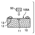
- the intermediate member 50 has an upper surface in contact with the distal end surface of the optical fiber 40 and a lower surface in contact with the light emitting portion 11 of the optical element 10.
- the intermediate member 50 constituting the optical path of the optical signal is made of, for example, glass through which the light of the optical signal is transmitted.
- the intermediate member 50 is bonded to the light emitting portion 11 of the light emitting surface 10SA of the optical element 10 with a transparent adhesive (not shown).
- the lower surface of the intermediate member 50 completely covers the light emitting unit 11 in order to efficiently guide the light generated by the optical element 10 to the optical fiber 40.
- the lower surface of the intermediate member 50 completely covers the light emitting unit 11 in order to efficiently guide the light generated by the optical element 10 to the optical fiber 40.
- it is.
- the intermediate member 50 may be a transparent resin such as a silicone resin, an epoxy resin, or an acrylic resin, as long as it is a material that allows the wavelength of the optical signal to be transmitted satisfactorily. Further, when the wavelength of the optical signal is an infrared wavelength, the intermediate member does not transmit visible light, but may be formed of a material that transmits infrared light, for example, silicon.
- the wiring board 20 and the optical element 10 are joined. That is, the bonding electrode 21 on the first main surface 20SA of the wiring board 20 and the external electrode 12 of the optical element 10 are bonded via the gold bump 13.
- a resin having a light shielding function that does not transmit light of an optical signal may be used as the sealing resin.
- the holding member 30 is bonded to the back surface 20SA of the substrate 20 on which the optical element 10 is mounted. Then, the optical fiber 40 is inserted and fitted into the through hole H30 of the holding member 30 up to a position where the distal end surface comes into contact with the upper surface of the intermediate member 50. The distance between the front end surface of the optical fiber 40 and the light emitting portion 11 of the optical element 10 is accurately positioned by the height of the holding member 30 and fixed by the adhesive 32.
- the optical transmission module 1 has a high coupling efficiency between the optical fiber 40 and the optical element 10 and is easy to manufacture.
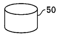
- the shape of the intermediate member is not limited to the cylindrical intermediate member 50 shown in FIG. 5A as long as the lower surface covers the light emitting unit 11.
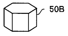
- the rectangular column intermediate member 50A shown in FIG. 5B or the polygonal column intermediate member 50B shown in FIG. 5C may be used.
- an intermediate member 50C having the same configuration as that of the optical fiber 40 as shown in FIG. 5D It is particularly preferable to use an intermediate member 50C having the same configuration as that of the optical fiber 40 as shown in FIG. 5D. That is, the intermediate member 50C having the clad portion 42 that covers the outer peripheral surface of the core portion 41 in the same manner as the optical fiber 40 has the optical fiber 40 of a predetermined length, that is, the tip surface of the optical fiber 40 and the optical element 10. It can be easily manufactured by cutting it at a distance from the light emitting portion 11. Further, the intermediate member 50C having the same configuration as the optical fiber 40 has high light transmission efficiency.
- the lower surface of the core portion 41 of the intermediate member 50C completely covers the light emitting portion 11 in order to guide the light generated by the optical element 10 to the optical fiber 40 efficiently.
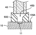
- the intermediate member 50 ⁇ / b> D has a cylindrical shape, that is, a hollow cylindrical shape, and has a through hole H ⁇ b> 50 that is a space serving as an optical path at the center.
- the intermediate member 50D is made of metal, ceramic, resin, or the like.
- the diameter R50 of the through hole H50 of the intermediate member 50D is larger than the outer diameter R11 of the light emitting part 11, and the core part 41 of the optical fiber 40 Is preferably smaller than the outer diameter R41.
- the diameter R50 of the through hole H50 of the intermediate member 50D is conversely smaller than the outer diameter R11 of the light receiving part and the outer diameter R41 of the core part 41 of the optical fiber 40. Is preferably larger.
- the length L50 of the intermediate member 50D is smaller than the distance between the light receiving surface 10SA of the optical element 10 and the lower surface of the holding member 30.
- the optical transmission module 1A can be manufactured at a lower cost than the optical transmission module 1.
- the inside of the through hole H50 may be filled with a transparent resin such as a silicone resin, an epoxy resin, or an acrylic resin.
- a transparent resin such as a silicone resin, an epoxy resin, or an acrylic resin.
- the intermediate member 50D is similar to the intermediate member 50.
- the opening on the upper surface of the through hole H50 has a tapered shape.
- the tip surface of the optical fiber 40 is in contact with the tapered surface.
- the intermediate member 50E can easily arrange the optical fiber 40 perpendicular to the light emitting surface 10SA of the optical element 10.
- the intermediate member 50F shown in FIG. 8B has an outer peripheral surface that is tapered toward the lower surface. Even when the external electrode 12 is disposed near the light emitting portion 11 of the optical element 10, the intermediate member 50 ⁇ / b> F can be easily disposed on the optical element 10.
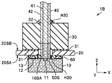
- optical transmission module 1B according to a third embodiment and an endoscope 2B having the optical transmission module 1B will be described. Since the optical transmission module 1B and the endoscope 2B are similar to the optical transmission module 1 and the endoscope 2 and have the same functions, the same components are denoted by the same reference numerals and description thereof is omitted.
- the intermediate member 50 ⁇ / b> G is long, and the upper part thereof is inserted through the hole H ⁇ b> 20 of the wiring board 20 to the through hole H ⁇ b> 30 of the holding member 30.
- the intermediate member 50G has the same configuration as that of the optical fiber 40, like the holding member 50C (see FIG. 5C). That is, the intermediate member 50G includes a core portion 41 and a cladding portion 42 having an outer diameter R50. However, the intermediate member 50G has a length L50 longer than the holding member 50C.
- the intermediate member 50G is bonded to the light emitting surface 10SA in a state of being aligned with the light emitting unit 11 of the optical element 10.
- the upper part of the intermediate member 50 ⁇ / b> G is inserted into the hole H ⁇ b> 20 of the substrate 20.
- the upper part of the intermediate member 50G is inserted into the through hole H30 of the holding member 30. That is, the outer diameter R50 of the intermediate member 50G is substantially the same size as the diameter of the through hole H30 of the holding member 30 in the same manner as the outer diameter R40 of the optical fiber 40.
- the optical element 10 and the holding member 30 are automatically positioned in the horizontal direction (XY direction). Then, the wiring board 20 and the optical element 10 are joined.
- the optical fiber 40 is automatically inserted into the through-hole H30, and the front end surface comes into contact with the upper surface of the intermediate member 50G, so that the optical fiber 40 is automatically not only in the horizontal direction (XY direction) but also in the vertical direction. Positioning is also performed in the direction (Z direction).
- the light transmission module 1B is easier to manufacture than the light transmission module 1 or the like.
- the same effect as that of the optical transmission module 1B can be obtained by using an intermediate member having the same configuration as the intermediate members 50 to 50D and having a long length instead of the intermediate member 50G. That is, in the optical transmission module in which the upper part of the intermediate member is inserted through the hole of the wiring board and inserted into the through hole of the holding member, the optical fiber is inserted into the through hole, and the tip end surface is in contact with the upper surface of the intermediate member. Thus, positioning is automatically performed not only in the horizontal direction (XY direction) but also in the vertical direction (Z direction) with respect to the light emitting unit.
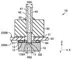
- the upper part of the intermediate member 50 ⁇ / b> H is tapered at the entire circumference, and the upper part is inserted through the hole H ⁇ b> 20 of the wiring board 20 and the through hole H ⁇ b> 30 of the holding member 30. Is inserted and fitted.
- the optical transmission module 1C is easy to insert the upper part of the intermediate member 50H into the through hole H30 of the holding member 30. For this reason, the optical transmission module 1C is easier to manufacture than the optical transmission module 1B.
- the outer diameter R50 of the intermediate member 50I is smaller than the outer diameter R40 of the optical fiber 40.
- the diameter of the through hole H30 of the holding member 30 is different between the upper part and the lower part. That is, in the through hole H30, the upper diameter R50 is substantially the same as the outer diameter R40 of the optical fiber 40, and the lower diameter R50A is substantially the same as the outer diameter R50 of the intermediate member 50I.
- the light transmission module 1D has the same effect as the light transmission module 1B.
- the cross-sectional shape of the lower part of the through-hole H30 of the holding member 30 is made rectangular or polygonal. The same effect as that of the transmission module 1B can be obtained.
- optical transmission module etc. which comprise the light emitting element as the optical element 10 were demonstrated above as an example.
- the optical element is an O / E optical transmission module of a light receiving element having a light receiving portion such as a photodiode, the same effect can be obtained as long as it has the same configuration.
- the O / E light transmission module disposed at the distal end portion of the endoscope transmits, for example, a clock signal input to the image sensor as an optical signal.
- An endoscope that transmits a clock signal through a thin optical fiber 40 has a thin insertion portion 80 and is minimally invasive.
- an optical fiber that transmits an optical signal, a light receiving unit on which the optical signal is incident, and an external electrode are disposed on the front surface.
- a light receiving element, a holding member having a through hole into which the optical fiber is inserted, and a hole serving as an optical path for the optical signal, and the holding member is bonded to the first main surface.
- an intermediate member having an upper surface in contact with the front end surface of the optical fiber and a lower surface in contact with the light receiving portion of the light receiving element.
Landscapes
- Health & Medical Sciences (AREA)
- Life Sciences & Earth Sciences (AREA)
- Surgery (AREA)
- Physics & Mathematics (AREA)
- Optics & Photonics (AREA)
- Engineering & Computer Science (AREA)
- Biomedical Technology (AREA)
- Veterinary Medicine (AREA)
- Biophysics (AREA)
- Pathology (AREA)
- Radiology & Medical Imaging (AREA)
- Nuclear Medicine, Radiotherapy & Molecular Imaging (AREA)
- Public Health (AREA)
- Heart & Thoracic Surgery (AREA)
- Medical Informatics (AREA)
- Molecular Biology (AREA)
- Animal Behavior & Ethology (AREA)
- General Health & Medical Sciences (AREA)
- Signal Processing (AREA)
- Astronomy & Astrophysics (AREA)
- General Physics & Mathematics (AREA)
- Multimedia (AREA)
- Endoscopes (AREA)
- Optical Couplings Of Light Guides (AREA)
- Instruments For Viewing The Inside Of Hollow Bodies (AREA)
Abstract
La présente invention concerne un module de transmission optique 1 qui est pourvu : d'une fibre optique 40 ; d'un élément d'émission de lumière 10 ; d'un élément de support 30 présentant un trou traversant H30 dans lequel est insérée la fibre optique 40 ; d'une carte de câblage 20, dans laquelle l'élément de support 30 est collé à une première surface principale 20SA et d'une électrode de liaison 21 disposée sur une seconde surface principale 20SB ainsi que d'une électrode externe 12 de l'élément d'émission de lumière 10 qui sont liées l'une à l'autre et d'une résine d'étanchéité 60 qui scelle une section de liaison entre l'électrode externe 12 et l'électrode de liaison 21. Le module de transmission optique est également pourvu d'un élément intermédiaire 50 ayant sa surface supérieure en contact avec la surface d'extrémité avant de la fibre optique 40 et sa surface inférieure en contact avec une section d'émission de lumière 11 de l'élément d'émission de lumière 10.
Priority Applications (3)
| Application Number | Priority Date | Filing Date | Title |
|---|---|---|---|
| PCT/JP2015/065232 WO2016189691A1 (fr) | 2015-05-27 | 2015-05-27 | Endoscope et module de transmission optique |
| JP2017520155A JPWO2016189691A1 (ja) | 2015-05-27 | 2015-05-27 | 内視鏡および光伝送モジュール |
| US15/811,952 US20180078114A1 (en) | 2015-05-27 | 2017-11-14 | Endoscope and optical transmission module |
Applications Claiming Priority (1)
| Application Number | Priority Date | Filing Date | Title |
|---|---|---|---|
| PCT/JP2015/065232 WO2016189691A1 (fr) | 2015-05-27 | 2015-05-27 | Endoscope et module de transmission optique |
Related Child Applications (1)
| Application Number | Title | Priority Date | Filing Date |
|---|---|---|---|
| US15/811,952 Continuation US20180078114A1 (en) | 2015-05-27 | 2017-11-14 | Endoscope and optical transmission module |
Publications (1)
| Publication Number | Publication Date |
|---|---|
| WO2016189691A1 true WO2016189691A1 (fr) | 2016-12-01 |
Family
ID=57392977
Family Applications (1)
| Application Number | Title | Priority Date | Filing Date |
|---|---|---|---|
| PCT/JP2015/065232 Ceased WO2016189691A1 (fr) | 2015-05-27 | 2015-05-27 | Endoscope et module de transmission optique |
Country Status (3)
| Country | Link |
|---|---|
| US (1) | US20180078114A1 (fr) |
| JP (1) | JPWO2016189691A1 (fr) |
| WO (1) | WO2016189691A1 (fr) |
Cited By (9)
| Publication number | Priority date | Publication date | Assignee | Title |
|---|---|---|---|---|
| WO2018139406A1 (fr) * | 2017-01-24 | 2018-08-02 | オリンパス株式会社 | Endoscope et procédé de fabrication d'endoscope |
| WO2018138778A1 (fr) * | 2017-01-24 | 2018-08-02 | オリンパス株式会社 | Endoscope |
| US20180289263A1 (en) * | 2017-03-30 | 2018-10-11 | Nan M. Jokerst | Devices and methods for endoscopic optical assessment of tissue histology |
| WO2020065757A1 (fr) * | 2018-09-26 | 2020-04-02 | オリンパス株式会社 | Dispositif d'imagerie endoscopique, endoscope, et procédé de production de dispositif d'imagerie endoscopique |
| WO2020079754A1 (fr) * | 2018-10-16 | 2020-04-23 | オリンパス株式会社 | Transducteur optique pour endoscope, endoscope, et procédé de fabrication de transducteur optique pour endoscope |
| WO2020178972A1 (fr) * | 2019-03-05 | 2020-09-10 | オリンパス株式会社 | Transducteur optique d'endoscope, endoscope, et procédé de fabrication de transducteur optique d'endoscope |
| JP2021140879A (ja) * | 2020-03-02 | 2021-09-16 | 富士通クライアントコンピューティング株式会社 | 電子機器及びホルダ |
| JP2024503142A (ja) * | 2021-03-08 | 2024-01-24 | ペンタックス メディカル ブルガリア エルティーディー. | 光ガイドを挿入するためのホルダを備える内視鏡 |
| US12611095B2 (en) | 2021-03-08 | 2026-04-28 | Pentax Medical Bulgaria Ltd. | Endoscope comprising holder for inserting a light guide |
Citations (5)
| Publication number | Priority date | Publication date | Assignee | Title |
|---|---|---|---|---|
| JP2007271674A (ja) * | 2006-03-30 | 2007-10-18 | Kyocera Corp | 光デバイス |
| JP2009251224A (ja) * | 2008-04-04 | 2009-10-29 | Sumitomo Electric Ind Ltd | 光モジュール及びその組立方法 |
| JP2013025092A (ja) * | 2011-07-21 | 2013-02-04 | Olympus Corp | 光素子モジュール、光伝送モジュール、および光伝送モジュールの製造方法 |
| JP2015087744A (ja) * | 2013-09-26 | 2015-05-07 | オリンパス株式会社 | 光伝送モジュールおよび内視鏡 |
| WO2015072225A1 (fr) * | 2013-11-18 | 2015-05-21 | オリンパス株式会社 | Endoscope |
Family Cites Families (9)
| Publication number | Priority date | Publication date | Assignee | Title |
|---|---|---|---|---|
| DE3382085D1 (de) * | 1982-07-31 | 1991-02-07 | Sumitomo Electric Industries | Lichtleitersonde. |
| JP2003110802A (ja) * | 2001-09-27 | 2003-04-11 | Fuji Photo Film Co Ltd | 撮像装置 |
| US20030071318A1 (en) * | 2001-10-11 | 2003-04-17 | Szu-Chun Wang | Optical sub-assembly housing structure for an optical transceiver module |
| US20040252951A1 (en) * | 2003-05-12 | 2004-12-16 | Seiko Epson Corporation | Optical module and manufacturing method of the same |
| US20070278666A1 (en) * | 2004-04-13 | 2007-12-06 | Jean-Charles Garcia | Method for Production of Electronic and Optoelectronic Circuits |
| BRPI0919834B8 (pt) * | 2008-10-20 | 2022-07-19 | Omron Tateisi Electronics Co | Projetor de luz e sensor |
| DE102010028167A1 (de) * | 2010-04-23 | 2011-10-27 | W.O.M. World Of Medicine Ag | Invasives Instrument zur Bearbeitung von Gefäßen und ein Verfahren |
| JP5704878B2 (ja) * | 2010-09-30 | 2015-04-22 | オリンパス株式会社 | 光電気変換コネクタ、光伝送モジュール、撮像装置および内視鏡 |
| JP6321933B2 (ja) * | 2013-09-26 | 2018-05-09 | オリンパス株式会社 | 光伝送モジュール、及び内視鏡 |
-
2015
- 2015-05-27 WO PCT/JP2015/065232 patent/WO2016189691A1/fr not_active Ceased
- 2015-05-27 JP JP2017520155A patent/JPWO2016189691A1/ja active Pending
-
2017
- 2017-11-14 US US15/811,952 patent/US20180078114A1/en not_active Abandoned
Patent Citations (5)
| Publication number | Priority date | Publication date | Assignee | Title |
|---|---|---|---|---|
| JP2007271674A (ja) * | 2006-03-30 | 2007-10-18 | Kyocera Corp | 光デバイス |
| JP2009251224A (ja) * | 2008-04-04 | 2009-10-29 | Sumitomo Electric Ind Ltd | 光モジュール及びその組立方法 |
| JP2013025092A (ja) * | 2011-07-21 | 2013-02-04 | Olympus Corp | 光素子モジュール、光伝送モジュール、および光伝送モジュールの製造方法 |
| JP2015087744A (ja) * | 2013-09-26 | 2015-05-07 | オリンパス株式会社 | 光伝送モジュールおよび内視鏡 |
| WO2015072225A1 (fr) * | 2013-11-18 | 2015-05-21 | オリンパス株式会社 | Endoscope |
Cited By (15)
| Publication number | Priority date | Publication date | Assignee | Title |
|---|---|---|---|---|
| WO2018138778A1 (fr) * | 2017-01-24 | 2018-08-02 | オリンパス株式会社 | Endoscope |
| WO2018138962A1 (fr) * | 2017-01-24 | 2018-08-02 | オリンパス株式会社 | Endoscope |
| WO2018139406A1 (fr) * | 2017-01-24 | 2018-08-02 | オリンパス株式会社 | Endoscope et procédé de fabrication d'endoscope |
| US10819960B2 (en) | 2017-01-24 | 2020-10-27 | Olympus Corporation | Endoscope |
| US10972707B2 (en) | 2017-01-24 | 2021-04-06 | Olympus Corporation | Endoscope and method of manufacturing endoscope |
| US20180289263A1 (en) * | 2017-03-30 | 2018-10-11 | Nan M. Jokerst | Devices and methods for endoscopic optical assessment of tissue histology |
| WO2020065757A1 (fr) * | 2018-09-26 | 2020-04-02 | オリンパス株式会社 | Dispositif d'imagerie endoscopique, endoscope, et procédé de production de dispositif d'imagerie endoscopique |
| US11986154B2 (en) | 2018-10-16 | 2024-05-21 | Olympus Corporation | Optical transducer for endoscope, endoscope, and manufacturing method of optical transducer for endoscope |
| WO2020079754A1 (fr) * | 2018-10-16 | 2020-04-23 | オリンパス株式会社 | Transducteur optique pour endoscope, endoscope, et procédé de fabrication de transducteur optique pour endoscope |
| WO2020178972A1 (fr) * | 2019-03-05 | 2020-09-10 | オリンパス株式会社 | Transducteur optique d'endoscope, endoscope, et procédé de fabrication de transducteur optique d'endoscope |
| US11971534B2 (en) | 2019-03-05 | 2024-04-30 | Olympus Corporation | Optical transducer for endoscope, endoscope, and manufacturing method of optical transducer for endoscope |
| JP2021140879A (ja) * | 2020-03-02 | 2021-09-16 | 富士通クライアントコンピューティング株式会社 | 電子機器及びホルダ |
| JP2024503142A (ja) * | 2021-03-08 | 2024-01-24 | ペンタックス メディカル ブルガリア エルティーディー. | 光ガイドを挿入するためのホルダを備える内視鏡 |
| JP7642077B2 (ja) | 2021-03-08 | 2025-03-07 | ペンタックス メディカル ブルガリア エルティーディー. | 光ガイドを挿入するためのホルダを備える内視鏡 |
| US12611095B2 (en) | 2021-03-08 | 2026-04-28 | Pentax Medical Bulgaria Ltd. | Endoscope comprising holder for inserting a light guide |
Also Published As
| Publication number | Publication date |
|---|---|
| US20180078114A1 (en) | 2018-03-22 |
| JPWO2016189691A1 (ja) | 2018-03-15 |
Similar Documents
| Publication | Publication Date | Title |
|---|---|---|
| JP6411088B2 (ja) | 光伝送モジュールおよび内視鏡 | |
| WO2016189691A1 (fr) | Endoscope et module de transmission optique | |
| US9385249B2 (en) | Optical element module, optical transmission module, and method of manufacturing optical transmission module | |
| JP6321933B2 (ja) | 光伝送モジュール、及び内視鏡 | |
| US20190384013A1 (en) | Optical module, endoscope and manufacturing method of optical module | |
| JP6230388B2 (ja) | 内視鏡 | |
| US10088669B2 (en) | Endoscope | |
| JPWO2016185537A1 (ja) | 内視鏡、および光伝送モジュール | |
| WO2018198188A1 (fr) | Endoscope et module d'imagerie | |
| WO2018092233A1 (fr) | Module optique, module de capture d'image et endoscope | |
| JP6485840B2 (ja) | 光伝送モジュールおよび内視鏡 | |
| WO2018138962A1 (fr) | Endoscope | |
| WO2018134933A1 (fr) | Module de optique et endoscope | |
| WO2018092234A1 (fr) | Module optique,capture d'image et endoscope | |
| US10470642B2 (en) | Optical transmitter and endoscope | |
| JP2015097588A (ja) | 光伝送モジュール及び内視鏡 | |
| WO2020075253A1 (fr) | Dispositif d'imagerie endoscopique, endoscope et procédé de fabrication de dispositif d'imagerie endoscopique | |
| JP2018105907A (ja) | 光モジュールおよび内視鏡 | |
| WO2020217277A1 (fr) | Procédé de fabrication d'un dispositif d'imagerie destiné à un endoscope, dispositif d'imagerie destiné à un endoscope, et endoscope | |
| WO2017115413A1 (fr) | Module de transmission optique, et endoscope |
Legal Events
| Date | Code | Title | Description |
|---|---|---|---|
| 121 | Ep: the epo has been informed by wipo that ep was designated in this application |
Ref document number: 15893325 Country of ref document: EP Kind code of ref document: A1 |
|
| ENP | Entry into the national phase |
Ref document number: 2017520155 Country of ref document: JP Kind code of ref document: A |
|
| NENP | Non-entry into the national phase |
Ref country code: DE |
|
| 122 | Ep: pct application non-entry in european phase |
Ref document number: 15893325 Country of ref document: EP Kind code of ref document: A1 |