WO2016189694A1 - 交流回転機の制御装置および電動パワーステアリングの制御装置 - Google Patents
交流回転機の制御装置および電動パワーステアリングの制御装置 Download PDFInfo
- Publication number
- WO2016189694A1 WO2016189694A1 PCT/JP2015/065241 JP2015065241W WO2016189694A1 WO 2016189694 A1 WO2016189694 A1 WO 2016189694A1 JP 2015065241 W JP2015065241 W JP 2015065241W WO 2016189694 A1 WO2016189694 A1 WO 2016189694A1
- Authority
- WO
- WIPO (PCT)
- Prior art keywords
- command
- position estimation
- current
- winding
- rotating machine
- Prior art date
- Legal status (The legal status is an assumption and is not a legal conclusion. Google has not performed a legal analysis and makes no representation as to the accuracy of the status listed.)
- Ceased
Links
Images











Classifications
-
- B—PERFORMING OPERATIONS; TRANSPORTING
- B62—LAND VEHICLES FOR TRAVELLING OTHERWISE THAN ON RAILS
- B62D—MOTOR VEHICLES; TRAILERS
- B62D5/00—Power-assisted or power-driven steering
- B62D5/04—Power-assisted or power-driven steering electrical, e.g. using an electric servo-motor connected to, or forming part of, the steering gear
- B62D5/0457—Power-assisted or power-driven steering electrical, e.g. using an electric servo-motor connected to, or forming part of, the steering gear characterised by control features of the drive means as such
- B62D5/046—Controlling the motor
- B62D5/0463—Controlling the motor calculating assisting torque from the motor based on driver input
-
- H—ELECTRICITY
- H02—GENERATION; CONVERSION OR DISTRIBUTION OF ELECTRIC POWER
- H02P—CONTROL OR REGULATION OF ELECTRIC MOTORS, ELECTRIC GENERATORS OR DYNAMO-ELECTRIC CONVERTERS; CONTROLLING TRANSFORMERS, REACTORS OR CHOKE COILS
- H02P21/00—Arrangements or methods for the control of electric machines by vector control, e.g. by control of field orientation
- H02P21/05—Arrangements or methods for the control of electric machines by vector control, e.g. by control of field orientation specially adapted for damping motor oscillations, e.g. for reducing hunting
-
- H—ELECTRICITY
- H02—GENERATION; CONVERSION OR DISTRIBUTION OF ELECTRIC POWER
- H02P—CONTROL OR REGULATION OF ELECTRIC MOTORS, ELECTRIC GENERATORS OR DYNAMO-ELECTRIC CONVERTERS; CONTROLLING TRANSFORMERS, REACTORS OR CHOKE COILS
- H02P21/00—Arrangements or methods for the control of electric machines by vector control, e.g. by control of field orientation
- H02P21/24—Vector control not involving the use of rotor position or rotor speed sensors
-
- H—ELECTRICITY
- H02—GENERATION; CONVERSION OR DISTRIBUTION OF ELECTRIC POWER
- H02P—CONTROL OR REGULATION OF ELECTRIC MOTORS, ELECTRIC GENERATORS OR DYNAMO-ELECTRIC CONVERTERS; CONTROLLING TRANSFORMERS, REACTORS OR CHOKE COILS
- H02P23/00—Arrangements or methods for the control of AC motors characterised by a control method other than vector control
-
- H—ELECTRICITY
- H02—GENERATION; CONVERSION OR DISTRIBUTION OF ELECTRIC POWER
- H02P—CONTROL OR REGULATION OF ELECTRIC MOTORS, ELECTRIC GENERATORS OR DYNAMO-ELECTRIC CONVERTERS; CONTROLLING TRANSFORMERS, REACTORS OR CHOKE COILS
- H02P6/00—Arrangements for controlling synchronous motors or other dynamo-electric motors using electronic commutation dependent on the rotor position; Electronic commutators therefor
- H02P6/10—Arrangements for controlling torque ripple, e.g. providing reduced torque ripple
-
- H—ELECTRICITY
- H02—GENERATION; CONVERSION OR DISTRIBUTION OF ELECTRIC POWER
- H02P—CONTROL OR REGULATION OF ELECTRIC MOTORS, ELECTRIC GENERATORS OR DYNAMO-ELECTRIC CONVERTERS; CONTROLLING TRANSFORMERS, REACTORS OR CHOKE COILS
- H02P6/00—Arrangements for controlling synchronous motors or other dynamo-electric motors using electronic commutation dependent on the rotor position; Electronic commutators therefor
- H02P6/14—Electronic commutators
- H02P6/16—Circuit arrangements for detecting position
- H02P6/18—Circuit arrangements for detecting position without separate position detecting elements
-
- H—ELECTRICITY
- H02—GENERATION; CONVERSION OR DISTRIBUTION OF ELECTRIC POWER
- H02P—CONTROL OR REGULATION OF ELECTRIC MOTORS, ELECTRIC GENERATORS OR DYNAMO-ELECTRIC CONVERTERS; CONTROLLING TRANSFORMERS, REACTORS OR CHOKE COILS
- H02P6/00—Arrangements for controlling synchronous motors or other dynamo-electric motors using electronic commutation dependent on the rotor position; Electronic commutators therefor
- H02P6/14—Electronic commutators
- H02P6/16—Circuit arrangements for detecting position
- H02P6/18—Circuit arrangements for detecting position without separate position detecting elements
- H02P6/183—Circuit arrangements for detecting position without separate position detecting elements using an injected high frequency signal
-
- H—ELECTRICITY
- H02—GENERATION; CONVERSION OR DISTRIBUTION OF ELECTRIC POWER
- H02P—CONTROL OR REGULATION OF ELECTRIC MOTORS, ELECTRIC GENERATORS OR DYNAMO-ELECTRIC CONVERTERS; CONTROLLING TRANSFORMERS, REACTORS OR CHOKE COILS
- H02P9/00—Arrangements for controlling electric generators for the purpose of obtaining a desired output
- H02P9/06—Control effected upon clutch or other mechanical power transmission means and dependent upon electric output value of the generator
-
- H—ELECTRICITY
- H02—GENERATION; CONVERSION OR DISTRIBUTION OF ELECTRIC POWER
- H02P—CONTROL OR REGULATION OF ELECTRIC MOTORS, ELECTRIC GENERATORS OR DYNAMO-ELECTRIC CONVERTERS; CONTROLLING TRANSFORMERS, REACTORS OR CHOKE COILS
- H02P25/00—Arrangements or methods for the control of AC motors characterised by the kind of AC motor or by structural details
- H02P25/16—Arrangements or methods for the control of AC motors characterised by the kind of AC motor or by structural details characterised by the circuit arrangement or by the kind of wiring
- H02P25/22—Multiple windings; Windings for more than three phases
-
- H—ELECTRICITY
- H02—GENERATION; CONVERSION OR DISTRIBUTION OF ELECTRIC POWER
- H02P—CONTROL OR REGULATION OF ELECTRIC MOTORS, ELECTRIC GENERATORS OR DYNAMO-ELECTRIC CONVERTERS; CONTROLLING TRANSFORMERS, REACTORS OR CHOKE COILS
- H02P27/00—Arrangements or methods for the control of AC motors characterised by the kind of supply voltage
- H02P27/04—Arrangements or methods for the control of AC motors characterised by the kind of supply voltage using variable-frequency supply voltage, e.g. inverter or converter supply voltage
- H02P27/06—Arrangements or methods for the control of AC motors characterised by the kind of supply voltage using variable-frequency supply voltage, e.g. inverter or converter supply voltage using DC to AC converters or inverters
- H02P27/08—Arrangements or methods for the control of AC motors characterised by the kind of supply voltage using variable-frequency supply voltage, e.g. inverter or converter supply voltage using DC to AC converters or inverters with pulse width modulation
Definitions
- the present invention relates to a control device for an AC rotating machine and an electric power steering device provided with the control device.
- the rotational position information of the AC rotating machine and the current information flowing through the AC rotating machine are required.
- the rotational position information is obtained by separately attaching a rotational position sensor to the AC rotating machine.
- separately providing the rotational position sensor has a great disadvantage from the viewpoint of cost, space, and reliability. For this reason, a sensorless configuration using a rotational position estimated value is required instead of the rotational position sensor.
- Patent Document 1 relates to a rotating machine provided with a plurality of sets of a plurality of stators connected to each other at neutral points. Specifically, this Patent Document 1 includes an estimation unit and a stator phase separation unit.
- the estimation means superimposes a high-frequency voltage signal having a frequency higher than the electrical angular frequency, and estimates the rotation angle of the rotating machine based on the detected value of the high-frequency current flowing through the rotating machine according to the superimposed high-frequency voltage signal.
- the stator phase separation means makes the phase of the current flowing through the stator differ for at least a pair of the plurality of sets. Then, the estimating means increases the degree of utilization of the detected value of the high-frequency current related to the absolute value of the current flowing through the stator being a predetermined value or more.
- Patent Document 1 the phase of the current flowing through the stator is made different between a group composed of U, V, and W phases and a group composed of X, Y, and Z phases.
- the rotation angle is estimated on the basis of the current flowing in the pair that does not become the zero cross period, avoiding that the currents flowing through both sets simultaneously become the zero cross period.
- the same value is superimposed on the UVW winding side and the XYZ winding side as high-frequency voltage signals (vdhr, vqhr). For this reason, the high-frequency current signal flowing through the rotating machine according to the high-frequency voltage signal is in phase when viewed on the two rotation axes (dq axes) on the UVW winding side and the XYZ winding side.
- the present invention has been made to solve the above-described problems, and controls an AC rotating machine capable of suppressing torque ripple, vibration, and noise of a high-frequency voltage signal component and improving rotational position estimation accuracy. It is an object to obtain an apparatus and a control device for an electric power steering.
- the control apparatus for an AC rotating machine has a rotor structure that generates saliency, an AC rotating machine having a first three-phase winding and a second three-phase winding, and a first 3
- a first current detector that detects a current flowing through a phase winding as a first winding current
- a second current detector that detects a current flowing through a second three-phase winding as a second winding current
- the first voltage command is calculated so that the first winding current detected by the first current detector matches the first current command which is a command value for the first winding current, and the second voltage command is calculated.
- a controller that calculates a second voltage command so that the second winding current detected by the current detector matches a second current command that is a command value for the second winding current; and a first voltage A first power converter for applying a voltage to each phase of the first three-phase winding based on the command, and a second voltage command A second power converter for applying a voltage to each phase of the second three-phase winding; and a first position estimation command having a first frequency and a second position estimation having a first frequency. Based on at least one of the first winding current and the second winding current, and the position estimation command generator for generating the command for use, the amplitude value of the first frequency component is extracted, and the alternating current is calculated from the magnitude of the amplitude value.
- a rotational position estimator that estimates the rotational position of the rotating machine, and the position estimation command generator outputs the first position estimation command and the second position estimation command with a phase difference between the first position estimation command and the control
- the device superimposes the first position estimation command on the first voltage command and outputs the first position command to the first power converter, and superimposes the second position estimation command on the second voltage command. Output to the power converter.
- the torque ripple, sound, vibration generated by the first position estimation command and the second position are determined.
- Torque ripple, sound, and vibration generated by the estimation command cause a phase difference.
- both commands have the same phase
- the added value of both the torque ripple, sound, and vibration is reduced. Therefore, compared with the prior art, torque ripple, sound, and vibration generated from the AC rotating machine can be reduced with respect to the amplitude values of the first position estimation command and the second position estimation command.
- the amplitudes of the first position estimation command and the second position estimation command can be set larger when it is desired to keep the torque ripple, vibration, and sound within a predetermined value.
- the present invention can improve the S / N ratio and reduce the influence of the quantization error due to the AD resolution as compared with the prior art. Therefore, the present invention has an unprecedented effect such as suppressing torque ripple, vibration, and noise of the high-frequency voltage signal component and improving the rotational position estimation accuracy.
- Embodiment 1 of this invention It is the figure which showed the waveform of each position calculation signal in Embodiment 1 of this invention.
- the first position estimation command and the second position estimation command when the torque ripple of the frequency component of the first position estimation command generated from the AC rotating machine is constant. It is the figure which showed the characteristic of the amplitude of each position calculation signal with respect to a phase difference. It is a figure which shows the whole structure of the control apparatus of the AC rotary machine in Embodiment 2 of this invention.
- the first position estimation command and the second position estimation command when the torque ripple of the frequency component of the first position estimation command generated from the AC rotating machine is constant. It is the figure which showed the characteristic of the amplitude of each position calculation signal with respect to a phase difference.
- the first position estimation command and the second position estimation command when the torque ripple of the frequency component of the first position estimation command generated from the AC rotating machine is constant. It is a characteristic view of the amplitude of the position estimation current with respect to the phase difference. It is a figure which shows the structure of the electric power steering which concerns on Embodiment 9 of this invention.
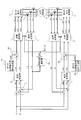
- FIG. 1 is a diagram showing an overall configuration of a control device for an AC rotating machine according to Embodiment 1 of the present invention.
- FIG. 2 is a figure for demonstrating the structure of the three-phase alternating current rotating machine used as an alternating current rotating machine in Embodiment 1 of this invention.
- the AC rotating machine 1a shown in FIG. 1 includes the first three-phase windings U1, V1, W1 connected at the neutral point N1, and the second connected at the neutral point N2.
- the three-phase windings U2, V2, and W2 are three-phase AC synchronous rotating machines that are housed in the stator of the rotating machine without being electrically connected.
- the U1 winding and U2 winding, the V1 winding and V2 winding, and the W1 winding and W2 winding each have a phase difference of 30 degrees.
- FIG. 2 the case where both the first three-phase winding and the second three-phase winding are Y-connected is illustrated as the AC rotating machine 1a, but the present invention is also applicable to the case of ⁇ -connection. It is.
- the rotor has a configuration in which a field magnetic flux is generated by a permanent magnet.
- the direction of the magnetic flux by the rotor is defined as the d-axis, and the direction advanced by 90 degrees in electrical angle from the d-axis is defined as the q-axis.
- the rotation position (rotation angle) of the d-axis with respect to the U1 winding is ⁇ degrees.
- the angle between the U2 winding and the d-axis is ⁇ -30 degrees.
- the rotor has a relationship of Ld ⁇ Lq between the d-axis inductance Ld and the q-axis inductance Lq of the AC rotating machine. That is, the AC rotating machine according to the first embodiment has a structure having saliency.
- the first current detector 2 is a first winding current i1u, i1v that flows through the first three-phase windings U1, V1, W1 of the AC rotating machine 1a by using a current detector such as a shunt resistor or a Hall element. , I1w is detected.
- the second current detector 3 is a second winding current i2u, i2v that flows through the second three-phase windings U2, V2, W2 of the AC rotating machine 1a by using a current detector such as a shunt resistor or a Hall element. , I2w is detected.
- the first power converter 4 uses a power converter such as an inverter or a matrix converter, based on a first voltage command v1u *, v1v *, v1w *, which will be described later, and a modulation process using an existing technique such as PWM or PAM. Is applied to each phase (U1, V1, W1) of the first three-phase winding of the AC rotating machine 1a.
- a power converter such as an inverter or a matrix converter
- the second power converter 5 uses a power converter such as an inverter or a matrix converter, based on second voltage commands v2u *, v2v *, and v2w *, which will be described later, to perform modulation processing using an existing technique such as PWM or PAM. Is applied to each phase (U2, V2, W2) of the second three-phase winding of the AC rotating machine 1a.
- a power converter such as an inverter or a matrix converter
- the coordinate converter 6 has two rotation axes (dq axes) based on the first winding currents i1u, i1v, i1w detected by the first current detector 2 and a rotation position estimated value ⁇ est described later. ) The first winding currents i1d and i1q above are calculated.
- the coordinate converter 7 generates two rotation axes (dq axes) based on the second winding currents i2u, i2v, i2w detected by the second current detector 3 and a rotation position estimated value ⁇ est described later. ) The second winding currents i2d and i2q above are calculated.
- the current command id * is a command value of the currents i1d and i2d on the two rotation axes (dq axes).
- the current command iq * is a command value for the currents i1q and i2q on the two rotation axes (dq axes).
- These current commands id * and iq * correspond to control commands for controlling the AC rotating machine 1a. Note that the control commands are not limited to the current commands id * and iq *.
- a speed command may be set as a control command.
- the coordinate converter 12 calculates the first three-phase voltage commands v1u * ′ and v1v * ′ from the first voltage commands v1d * and v1q * on the two rotation axes (dq axes) obtained from the current controller 10. , V1w * ′ is calculated.
- the coordinate converter 13 calculates the second three-phase voltage commands v2u * ′ and v2v * ′ from the second voltage commands v2d * and v2q * on the two rotation axes (dq axes) obtained from the current controller 11. , V2w * ′ is calculated.
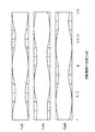
- FIG. 3 is a diagram showing a time change of the position estimation command output from each of the first position estimation command generator 14 and the second position estimation command generator 15 according to the first embodiment of the present invention. It is.
- the first position estimation command generator 14 outputs first position estimation commands v1uh *, v1vh *, and v1wh * with a period Th.
- the frequency (1 / Th) of the first position estimation command is set sufficiently higher than the electrical angular frequency according to the rotational speed of the AC rotating machine 1a.
- the frequency (1 / Th) of the position estimation command is set to be at least twice the electrical angular frequency corresponding to the rotational speed of the AC rotating machine 1a.
- v1vh * has a phase delay of 120 (60 ⁇ 2) degrees with respect to v1uh *
- v1wh * has a phase delay of 120 (60 ⁇ 2) degrees with respect to v1vh *.
- the amplitudes of v1uh *, v1vh *, and v1wh * are the same.
- the second position estimation command generator 15 outputs second position estimation commands v2uh *, v2vh *, and v2wh * with a period Th.
- the frequency (1 / Th) and amplitude of the second position estimation command are the same as those of the first position estimation command.
- v2uh *, v2vh *, and v2wh * have a phase difference of ⁇ [degree] with respect to v1uh *, v1vh *, and v1wh *, respectively. This phase difference ⁇ [degree] will be described later.
- the superimposer 16 superimposes the first position estimation commands v1uh *, v1vh *, v1wh * on the first voltage commands v1u * ′, v1v * ′, v1w * ′ that are the outputs of the coordinate converter 12.
- the first voltage commands v1u *, v1v *, v1w * are output.
- the superimposing unit 17 superimposes the second position estimation commands v2uh *, v2vh *, v2wh * on the second voltage commands v2u * ′, v2v * ′, v2w * ′ that are the outputs of the coordinate converter 13.
- the second voltage commands v2u *, v2v *, v2w * are output.
- FIG. 4 is a diagram showing an internal configuration of the rotational position estimator 18a according to Embodiment 1 of the present invention.
- the rotational position estimator 18a includes three current extractors 18a1u, 18a1v, 18a1w, an amplitude calculator 18ax, and a position calculator 18ay.
- the first position estimation commands v1uh *, v1vh *, and v1wh * are superimposed on the first three-phase voltage commands v1u *, v1v *, and v1w * by the superimposer 16.
- the first winding currents i1u, i1v, i1w include position estimation currents i1uh, i1vh, i1wh having the same frequency components as the position estimation command.
- the current extractors 18a1u, 18a1v, 18a1w are arranged at positions of the same frequency component as the first position estimation command from the first winding currents i1u, i1v, i1w detected by the first current detector 2.
- Currents for estimation i1uh, i1vh, i1wh are extracted.
- position estimation currents i1uh, i1vh, and i1wh can be extracted by using a band-pass filter.
- the first winding currents i1u, i1v, i1w are input to the notch filter to attenuate the same frequency components as the first position estimation commands v1uh *, v1vh *, v1wh *, and the first winding current i1u , I1v, i1w can be used to extract currents for position estimation i1uh, i1vh, i1wh.
- FIG. 5 is a diagram illustrating output waveforms of the current extractors 18a1u, 18a1v, and 18a1w according to Embodiment 1 of the present invention.
- the current extractors 18a1u As shown in FIG. 5, the amplitudes of the position estimation currents i1uh, i1vh, i1wh extracted by 18a1v, 18a1w change in a cosine function according to the rotational position ⁇ of the AC rotating machine 1a.
- Ih is an average value of the amplitude of the position estimation current
- Iha is an amount of change due to the rotational position of the position estimation current
- ⁇ h is an angular frequency of the position estimation command.
- the above equation (1) includes information on the rotational position ⁇ of the AC rotating machine 1a. Therefore, the estimated value ⁇ est for the rotational position ⁇ of the AC rotating machine 1a can be obtained by obtaining the position estimation currents I1uh, I1vh, I1wh.
- the effective value Ix is obtained by squaring the instantaneous value ix of the alternating current, integrating for one period Tx, multiplying by 1 / Tx, and calculating the square root. Further, the amplitude Ixamp of the alternating current ix is obtained by the following expression (3) using the effective value Ix.
- the amplitude calculator 18ax can obtain the amplitudes I1uh, I1vh, and I1wh of the position estimation current by executing the calculation according to the above equation (3). Specifically, the multipliers 18a2u, 18a2v, and 18a2w calculate the square values of the position estimation currents i1uh, i1vh, and i1wh. Next, the integrators 18a3u, 18a3v, and 18a3w integrate the square values of the position estimation currents i1uh, i1vh, and i1wh with a period Th, respectively, and perform a multiplication operation of 2 / Th.
- the multipliers 18a4u, 18a4v, and 18a4w calculate the amplitudes I1uh, I1vh, and I1wh of the position estimation current by performing square root operations on the calculation results of the integrators 18a3u, 18a3v, and 18a3w, respectively.
- FIG. 6 is a diagram showing an output waveform of the amplitude calculator 18ax according to the first embodiment of the present invention. As shown in FIG. 6, offsets Ih are superimposed on the amplitudes I1uh, I1vh, and I1wh of the position estimation current obtained by the amplitude calculator 18ax, and are half the rotation position ⁇ of the AC rotating machine 1a. Change.
- the position calculator 18ay first calculates the position calculation signals dI1uh, dI1vh, dI1wh by subtracting the offset Ih from the amplitudes I1uh, I1vh, I1wh of the position estimation current as shown in the following equation (4). To do.
- the offset Ih can be obtained from the following equation (5) because the amplitudes I1uh, I1vh, and I1wh of the position estimation current are in three-phase equilibrium.
- FIG. 7 is a diagram showing waveforms of the position calculation signals dI1uh, dI1vh, and dI1wh according to Embodiment 1 of the present invention. As shown in FIG. 7, each of the position calculation signals dI1uh, dI1vh, dI1wh becomes a balanced three-phase alternating current with no offset with respect to the rotational position ⁇ of the AC rotating machine 1a.
- the estimated position ⁇ est of the rotational position ⁇ can be calculated by performing an inverse cosine calculation on any one of the position calculation signals dI1uh, dI1vh, dI1wh.
- the estimated position ⁇ est of the rotational position ⁇ may be obtained from the following equation (6) based on the position calculation signals dI1uh, dI1vh, dI1wh.
- the estimation accuracy of the rotational position estimation value ⁇ est depends on the amplitude (Iha / 2) of each position calculation signal dI1uh, dI1vh, dI1wh.
- the estimation accuracy of the rotational position estimation value ⁇ est is improved.
- the control device for the AC rotating machine suppresses the torque ripple generated from the AC rotating machine 1a within a certain predetermined value, and the amplitude (Iha / 2). As a result, the position estimation accuracy can be improved.
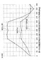
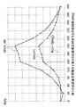
- FIG. 8 shows the first position estimation command and the second position estimation torque when the torque ripple of the frequency component of the first position estimation command generated from the AC rotating machine 1a is constant in the first embodiment of the present invention. It is the figure which showed the characteristic of the amplitude (Iha / 2) of each position calculation signal dI1uh, dI1vh, dI1wh with respect to the phase difference of the command for position estimation.
- the larger the amplitude, the larger the amplitude of the position estimation currents i1uh, i1vh, i1wh can be set for the same torque ripple, and the rotational position estimation accuracy can be improved.
- the position estimation command generated from the AC rotating machine 1a when the position estimation currents i1uh, i1vh, i1wh have the same amplitude (Iha constant). This means that the torque ripple of the component can be reduced.
- the phase difference ⁇ is provided between the first position estimation command and the second position estimation command.
- the phase difference ⁇ is set to 90. If the torque ripple of the frequency component of the position estimation command is to be within a predetermined value among the torque ripples generated from the AC rotating machine 1a by setting the angle within the range of not less than 300 degrees and not more than 300 degrees, the amplitude of the position estimation current Can be set larger. As a result, it is possible to improve the estimation accuracy of the estimated value of the rotational position of the AC rotating machine.
- the phase difference between the first three-phase winding and the second three-phase winding is 30 degrees, but the phase difference is not limited to 30 degrees.
- ⁇ Amplitude can be set larger in the range of X + 90 to X + 240 [degrees]
- FIG. FIG. 9 is a diagram showing an overall configuration of an AC rotating machine control apparatus according to Embodiment 2 of the present invention. Components corresponding to or corresponding to those of the first embodiment shown in FIG. 1 are given the same reference numerals.
- FIG. 9 in the second embodiment is different from the configuration of FIG. 1 in the first embodiment in the following two points.
- a point further including a subtractor 201 A point where the rotational position estimator 18a calculates an estimated value ⁇ est of the rotational position based on the output of the subtracter 201
- the subtractor 201 obtains the second winding currents i2u, i2v, i2w detected by the second current detector 3 from the first winding currents i1u, i1v, i1w detected by the first current detector 2. Subtraction values iu_dif, iv_dif, and iw_dif are calculated by subtraction. Then, the rotational position estimator 18a in the second embodiment calculates an estimated value ⁇ est of the rotational position based on the subtraction values iu_dif, iv_dif, iw_dif that are the outputs of the subtractor 201.
- FIG. 10 shows the first position estimation command and the second position estimation torque when the torque ripple of the frequency component of the first position estimation command generated from the AC rotating machine 1a is constant in the second embodiment of the present invention. It is the figure which showed the characteristic of the amplitude (Iha / 2) of each position calculation signal dI1uh, dI1vh, dI1wh with respect to the phase difference of the command for position estimation.
- the characteristic waveform indicated by “Iha / 2 (iu_dif, iv_dif, iw_dif)” in FIG. 10 is a subtraction value iu_dif, iv_dif, The characteristic when the estimated value ⁇ est of the rotational position is calculated based on iw_dif is shown.
- the characteristic waveform indicated by “Iha / 2 (i1u, i1v, i1w)” in FIG. 10 is based on the first winding currents i1u, i1v, i1w in the first embodiment.
- the characteristics when the estimated value ⁇ est is calculated are shown.
- the estimated value of the rotational position is calculated based on the subtraction value between the first winding current and the second winding current.
- the phase difference between the first three-phase winding and the second three-phase winding is 30 degrees, but the phase difference is 30 degrees. It is not limited to degrees.
- FIG. FIG. 11 is a diagram showing an overall configuration of an AC rotating machine control apparatus according to Embodiment 3 of the present invention. Components corresponding to or corresponding to those of the first embodiment shown in FIG. 1 are given the same reference numerals.
- FIG. 11 in the third embodiment is different from the configuration of FIG. 1 in the first embodiment in the following three points.
- the second position estimation command generator 15 the superimposer 16, and the superimposer 17
- the first position estimation command generator 301 the second position estimation
- the first voltage commands v1u *, v1v *, and v1w * are supplied to the first power converter 4 as they are, and the second three-phase voltage commands v2u * ′ and v2v output from the coordinate converter 13 are similarly applied.
- the point / rotation position estimator 18a that gives the second power command 5 as the second voltage commands v2u *, v2v *, v2w * as it is as the second voltage commands v2u *, * ', V1v *', v1w * 'based on the rotational position estimate ⁇ e Point for calculating the t
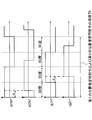
- FIG. 12 is a diagram showing a time change of the position estimation command output from each of the first position estimation command generator 301 and the second position estimation command generator 302 in the third embodiment of the present invention. It is.
- the first position estimation command generator 301 outputs a d-axis position estimation command i1dh * and a q-axis position estimation command i1qh *.
- the q-axis position estimation command i1qh * is delayed by 90 degrees relative to the d-axis position estimation command i1dh * that changes at a cycle Th of 360 degrees.
- the superimposer 303 outputs the addition result of i1dh * and id * and the addition result of i1qh * and iq * to the subtracter 8.
- the current controller 10 controls di1d and di1q to be 0. Accordingly, the first winding currents i1d and i1q on the two rotating axes are controlled to coincide with id * + i1dh * and iq * + i1qh *, respectively.
- the second position estimation command generator 302 outputs a d-axis position estimation command i2dh * and a q-axis position estimation command i2qh *.
- the q-axis position estimation command i2qh * is delayed by 90 degrees relative to the d-axis position estimation command i2dh * that changes at a cycle Th of 360 degrees.
- i2dh * has a phase difference ⁇ with respect to i1dh *
- i2qh * also has a phase difference ⁇ with respect to i1qh *.
- the combined vector of i2dh * and i2qh * is a rotation vector that rotates in the period Th on the dq coordinate shown in FIG. 2, and the combined vector of i1dh * and i1qh * and the phase difference ⁇ are Have.
- the superimposer 304 outputs the addition result of i2dh * and id * and the addition result of i2qh * and iq * to the subtracter 9.
- the current controller 11 controls di2d and di2q to be 0. Accordingly, the second winding currents i2d and i2q on the two rotating axes are controlled to coincide with id * + i2dh * and iq * + i2qh *, respectively.
- the components i1dh and i1qh of the position estimation command for the first winding current are assumed to be constant.
- the components i2dh and i2qh of the second winding current position estimation command also have a constant amplitude.
- the first three-phase voltage commands v1u * ', v1v *', v1w * 'and the second three-phase voltage commands v2u *', v2v * ', v2w *' The amplitude of the frequency component of the included position estimation command varies depending on the rotor position.
- FIG. 13 is a diagram showing an output waveform of the amplitude calculator 18ax according to the third embodiment of the present invention. Specifically, FIG. 13 shows the position estimation obtained by the amplitude calculator 18ax in the rotational position estimator 18a based on the first three-phase voltage commands v1u * ′, v1v * ′, and v1w * ′. The amplitudes V1u, V1v, and V1w of the frequency component of the command are shown.
- the position calculator 18ay can calculate the estimated value ⁇ est of the rotational position by extracting this variation.
- the first position estimation is performed.
- the torque ripple / vibration / sound by the command for use overlaps with the torque ripple / vibration / sound by the second position estimation command in the same phase.
- torque ripple, vibration, and sound generated from the AC rotating machine 1a increase, which is not preferable.
- the position estimation command is adjusted by adjusting the phase difference ⁇ between the first position estimation commands i1dh * and i1qh * and the second position estimation commands i2dh * and i2qh *.
- the first position estimation commands i1dh * and i1qh * and the second position estimation commands i2dh * and i2qh * can be increased while keeping the torque ripple within a predetermined value.
- further in the range of ⁇ X + 150 to X + 210 [degree].
- Amplitude can be set large.
- the third embodiment it is possible to increase the amplitude of the position estimation command with respect to the torque ripple, sound, and vibration of the frequency component of the predetermined position estimation command. The effect that the estimation accuracy can be improved is obtained.
- FIG. 14 is a diagram showing an overall configuration of an AC rotating machine control apparatus according to Embodiment 4 of the present invention. Components corresponding to or corresponding to those in the second embodiment shown in FIG. 9 and the third embodiment shown in FIG. 11 are given the same reference numerals.
- FIG. 14 in the fourth embodiment is different from the configuration of FIG. 11 in the previous third embodiment in the following two points.
- a point that the rotational position estimator 18a calculates an estimated value ⁇ est of the rotational position based on the output of the subtractor 401.
- the subtractor 401 uses the first three-phase voltage commands v1u * ′, v1v * ′, v1w * ′ calculated by the coordinate converter 12 to calculate the second three-phase voltage commands v2u * calculated by the coordinate converter 13. Subtracted values vu_dif, vv_dif, and vw_dif are calculated by subtracting “, v2v *” and v2w * ”. Then, the rotational position estimator 18a according to the fourth embodiment calculates an estimated value ⁇ est of the rotational position based on the subtraction values vu_dif, vv_dif, and vw_dif that are output from the subtractor 401.
- FIG. 15 shows the first position estimation command and the second position estimation torque when the torque ripple of the frequency component of the first position estimation command generated from the AC rotating machine 1a is constant in the fourth embodiment of the present invention. It is the figure which showed the characteristic of the amplitude (Vha / 2) of the command component for position estimation of the 1st 3 phase voltage command and the 2nd 3 phase voltage command with respect to the phase difference of the command for position estimation.
- the characteristic waveform indicated by “Vha / 2 (vu_dif, vv_dif, vw_dif)” in FIG. 15 is a subtraction value between the first three-phase voltage command and the second three-phase voltage command in the fourth embodiment. It shows characteristics when the estimated value ⁇ est of the rotational position is calculated based on vu_dif, vv_dif, and vw_dif.
- the characteristic waveform indicated by “Vha / 2 (v1u * ′, v1v * ′, v1w * ′)” in FIG. 15 represents the first three-phase voltage command v1u * ′ in the third embodiment.
- V1v * ′, v1w * ′ the characteristic when the estimated value ⁇ est of the rotational position is calculated is shown.
- the amplitude of the characteristic of the fourth embodiment can be set larger with respect to the same torque ripple than the characteristic of the third embodiment.
- the rotational position estimation value is calculated based on the subtraction value between the first three-phase voltage command and the second three-phase voltage command.
- the first position estimation command and the second position estimation command are superimposed on the three-phase stationary coordinates (uvvw coordinates).
- the present invention is not limited to such a coordinate system.
- the first position estimation command and the second position estimation command may be superimposed on the two-phase stationary coordinates ( ⁇ - ⁇ coordinates), and the same effect can be obtained.
- first position estimation command and the second position estimation command in the first to fourth embodiments described above are rotation vectors that rotate on a stationary coordinate with a period Th. Accordingly, the present invention also includes a method of performing such a rotation vector by superimposing the first position estimation command and the second position estimation command on the rotation biaxial (dq coordinate) coordinates. Needless to say. Therefore, in the following fifth to eighth embodiments, the case where the first position estimation command and the second position estimation command are superimposed on the two-phase stationary coordinates ( ⁇ - ⁇ coordinates) will be specifically described. To do.
- FIG. 16 is a diagram showing an overall configuration of an AC rotating machine control apparatus according to Embodiment 5 of the present invention. Components corresponding to or corresponding to those of the first embodiment shown in FIG. 1 are given the same reference numerals.
- FIG. 16 in the fifth embodiment is different from the configuration of FIG. 1 in the first embodiment in the following three points.
- the second position estimation command generator 15 the superimposer 16, and the superimposer 17
- a first position estimation command generator 501 a second position estimation
- the first voltage commands v1u *, v1v *, and v1w * are supplied to the first power converter 4 as they are, and the second three-phase voltage commands v2u * ′ and v2v output from the coordinate converter 13 are similarly applied.
- * ', V2w *' are used as second voltage commands v2u *, v2v *, v2w * as they are, instead of the point / rotation position estimator 18a given to the second power converter 5, a rotational position estimator 18b is used.
- the first winding current i1 on the two rotating axes Point for calculating the estimated value ⁇ est of the rotational position based on the
- FIG. 17 is a diagram showing a time change of the position estimation command output from each of the first position estimation command generator 501 and the second position estimation command generator 502 according to the fifth embodiment of the present invention. It is.
- the first position estimation command generator 501 outputs a first position estimation command v1dh * with a cycle Th as shown in FIG.
- the first position estimation command v1dh * is a component in a direction parallel to the estimated magnetic flux detected at the estimated position ⁇ est of the rotational position.
- the second position estimation command generator 502 outputs a second position estimation command v2dh * with a period Th.
- the second position estimation command v2dh * is a component in a direction parallel to the estimated magnetic flux detected at the estimated position ⁇ est of the rotational position.
- the second position estimation command V2dh * has a phase difference ⁇ [degree] with respect to the first position estimation command v1dh *.
- the superimposer 503 superimposes the first position estimation command v1dh * on the first d-axis voltage command v1d * output from the current controller 10 and outputs the first position estimation command v1dh * to the coordinate converter 12.
- the superimposer 504 superimposes the second position estimation command v2dh * on the second d-axis voltage command v2d * output from the current controller 11 and outputs the second position estimation command v2dh * to the coordinate converter 13.
- i1dh and i1qh are represented by the following formula (7).
- Ldest and Lquest mean the d-axis inductance and the q-axis inductance on the two rotation axes estimated at the estimated position ⁇ est of the rotation position.
- ⁇ 0, that is, only when the rotational position ⁇ of the AC rotating machine 1a matches the rotational position estimated value ⁇ est, the position estimation command component i1qh matches 0 and ⁇ ⁇ If it is 0, it does not match 0. Therefore, the rotational position estimator 18b performs an operation such that the position estimation command component i1qh is equal to 0, thereby matching the rotational position estimated value ⁇ est with the rotational position ⁇ of the AC rotating machine 1a.
- FIG. 18 is a block diagram showing the configuration of the rotational position estimator 18b according to Embodiment 5 of the present invention.
- the rotational position estimator 18b includes a band pass filter 505, an amplitude calculator 506, a subtractor 507, and a PI calculator 508.
- the band pass filter 505 inputs the first winding current i1q out of the first winding currents i1d and i1q on the two rotation axes, and extracts the component i1qh of the position estimation command included in the first winding current i1q. To do.
- the amplitude calculator 506 calculates the amplitude Iqh of the component i1qh of the position estimation command.
- the subtracter 507 calculates a deviation between 0 and Iqh calculated by the amplitude calculator 506.
- the PI calculator 508 performs proportional / integral control so that the deviation obtained by the subtractor 507 is 0, and outputs the estimated value ⁇ est of the rotational position.
- the first position estimation is performed.
- the torque ripple / vibration / sound by the command for use overlaps with the torque ripple / vibration / sound by the second position estimation command in the same phase.
- a phase difference ⁇ is provided between the first position estimation command v1dh * and the second position estimation command v2dh *, so that the first position estimation command A phase difference is generated between torque ripple / sound / vibration generated by the command v1dh * and torque ripple / sound / vibration generated by the second position estimation command v2dh *.
- the amplitude of the component i1qh of the position estimation command can be increased while suppressing the torque ripple generated from the AC rotating machine 1a within a certain predetermined value, and the amplitude value Iqh with respect to the estimated value ⁇ est of the rotational position is increased.
- the position estimation accuracy can be improved.
- FIG. 19 shows the first position estimation command and the second position estimation torque when the torque ripple of the frequency component of the first position estimation command generated from the AC rotating machine 1a is constant in the fifth embodiment of the present invention. It is the figure which showed the characteristic of amplitude value Iqh of the electric current for position estimation i1qh with respect to the phase difference of the instruction for position estimation. It is a characteristic diagram in which the horizontal axis represents the phase difference ⁇ and the vertical axis represents Iqh.
- the amplitude value Iqh of the position estimation current i1qh can be set larger with respect to the same torque ripple, and the rotational position estimation accuracy can be improved.
- the torque ripple of the component of the position estimation command generated from the AC rotating machine 1a can be reduced when the amplitude of the position estimation current i1qh is the same. I mean.
- the first position estimation command and the second position estimation command are superimposed on the component parallel to the estimated magnetic flux, and the phase difference between them is 30 degrees or more and 270 degrees.
- the configuration is set to the following range. As a result, it is possible to improve the estimation accuracy of the rotational position while suppressing the torque ripple of the frequency component of the position estimation command generated in the torque of the AC rotating machine.
- the first position estimation command and the second position estimation command are superimposed on the current command also in the fifth embodiment. Needless to say, the same effect can be obtained by estimating the rotational position based on the first voltage command v1q *.
- FIG. FIG. 20 is a diagram showing an overall configuration of an AC rotary machine control apparatus according to Embodiment 6 of the present invention. Components corresponding to or corresponding to those of the fifth embodiment shown in FIG. 16 are given the same reference numerals.
- FIG. 20 in the sixth embodiment is different from the configuration of FIG. 16 in the previous fifth embodiment in the following two points.
- a point that further includes a subtractor 601 A point that the rotational position estimator 18b calculates an estimated value ⁇ est of the rotational position based on the output of the subtractor 601
- the subtractor 601 subtracts the second winding current i2q on the two rotation axes calculated by the coordinate converter 7 from the first winding current i1q on the two rotation axes calculated by the coordinate converter 6.
- the subtraction value iq_dif is calculated.
- the rotational position estimator 18b calculates an estimated value ⁇ est of the rotational position based on the subtraction value iq_dif that is the output of the subtractor 601.
- FIG. 21 shows the first position estimation command and the second position estimation torque when the torque ripple of the frequency component of the first position estimation command generated from the AC rotating machine 1a is constant in the sixth embodiment of the present invention. It is a characteristic view of amplitude Iqh of position estimation current with respect to a phase difference of a position estimation command.
- the characteristic waveform indicated by “Iqh (iq_dif)” in FIG. 21 is an estimation of the rotational position based on the subtraction value iq_dif between the first winding current i1q and the second winding current i2q in the sixth embodiment.
- the characteristic when the value ⁇ est is calculated is shown.
- the characteristic waveform indicated by “Iqh (i1q)” in FIG. 21 shows the characteristic when the estimated rotational position value ⁇ est is calculated based on the first winding current i1q in the fifth embodiment. It is shown.
- the amplitude of the characteristic of the sixth embodiment can be set larger with respect to the same torque ripple than the characteristic of the previous fifth embodiment.
- the rotational position estimation value is calculated based on the subtraction value between the first winding current and the second winding current with respect to the q axis.
- the first position estimation command and the second position estimation command are superimposed on the current command also in the sixth embodiment. Needless to say, the same effect can be obtained even if the rotational position is estimated based on the subtracted value of the first voltage command v1q * and the second voltage command v2q *.
- FIG. 22 is a diagram showing an overall configuration of an AC rotating machine control device according to Embodiment 7 of the present invention. Components corresponding to or corresponding to those of the first embodiment shown in FIG. 1 are given the same reference numerals.
- FIG. 22 in the seventh embodiment is different from the configuration of FIG. 1 in the first embodiment in the following three points.
- a first position estimation command generator 701 a second position estimation The first three-phase voltage commands v1u * ′, v1v * ′, and v1w * ′ output from the point / coordinate converter 12 in which the command generator 702, the superimposer 703, and the superimposer 704 are arranged at different positions.
- the first voltage commands v1u *, v1v *, and v1w * are supplied to the first power converter 4 as they are, and the second three-phase voltage commands v2u * ′ and v2v output from the coordinate converter 13 are similarly applied.
- * 'And v2w *' are used as the second voltage commands v2u *, v2v * and v2w * as they are, instead of the point / rotation position estimator 18a given to the second power converter 5, a rotational position estimator 18c is used.
- the first winding current i1 on the two rotating axes Point for calculating the estimated value ⁇ est of the rotational position based on the
- FIG. 23 is a diagram showing a time change of the position estimation command output from each of the first position estimation command generator 701 and the second position estimation command generator 702 in Embodiment 7 of the present invention. It is.
- the first position estimation command generator 701 outputs a first position estimation command v1qh * with a period Th.
- the first position estimation command v1qh * is a component in a direction perpendicular to the estimated magnetic flux detected at the estimated position ⁇ est of the rotational position.
- the second position estimation command generator 702 outputs a second position estimation command v2qh * with a period Th.
- the second position estimation command v2qh * is a component in a direction perpendicular to the estimated magnetic flux detected at the estimated position ⁇ est of the rotational position.
- the second position estimation command v2qh * has a phase difference ⁇ [degree] with respect to the first position estimation command v1qh *.
- the superimposer 703 superimposes the first position estimation command v1qh * on the first q-axis voltage command v1q * output from the current controller 10 and outputs the first position estimation command v1qh * to the coordinate converter 12.
- the superimposer 704 superimposes the second position estimation command v2qh * on the second q-axis voltage command v2q * output from the current controller 11, and outputs the superposed signal to the coordinate converter 13.
- i1dh and i1qh are represented by the following formula (9).
- ⁇ 0, that is, only when the rotational position ⁇ of the AC rotating machine 1a matches the rotational position estimated value ⁇ est, the position estimation command component i1dh matches 0, and ⁇ ⁇ If it is 0, it does not match 0. Therefore, the rotational position estimator 18c performs an operation such that the position estimation command component i1dh is equal to 0, thereby matching the estimated value ⁇ est of the rotational position with the rotational position ⁇ of the AC rotating machine 1a.
- FIG. 24 is a block diagram showing a configuration of the rotational position estimator 18c according to the seventh embodiment of the present invention.
- the rotational position estimator 18c includes a bandpass filter 705, an amplitude calculator 706, a subtractor 707, and a PI calculator 708.
- the band-pass filter 705 inputs the first winding current i1d out of the first winding currents i1d and i1q on the two rotation axes, and extracts the position estimation command component i1dh included in the first winding current i1d. To do.
- the amplitude calculator 706 calculates the amplitude Idh of the component i1dh of the position estimation command.
- the subtractor 707 calculates a deviation between 0 and Idh calculated by the amplitude calculator 706.
- the PI calculator 708 performs proportional / integral control so that the deviation obtained by the subtractor 707 is zero, and outputs the estimated value ⁇ est of the rotational position.
- the first position estimation is performed.
- the torque ripple / vibration / sound by the command for use overlaps with the torque ripple / vibration / sound by the second position estimation command in the same phase.
- a phase difference ⁇ is provided between the first position estimation command v1qh * and the second position estimation command v2qh *, so that the first position estimation command A phase difference is generated between the torque ripple / sound / vibration generated by the command v1qh * and the torque ripple / sound / vibration generated by the second position estimation command v2qh *.
- FIG. 25 shows the first position estimation command and the second position estimation torque when the torque ripple of the frequency component of the first position estimation command generated from the AC rotating machine 1a is constant in the seventh embodiment of the present invention. It is the figure which showed the characteristic of amplitude value Idh of the electric current for position estimation i1dh with respect to the phase difference of the instruction for position estimation. It is a characteristic diagram in which the horizontal axis represents the phase difference ⁇ and the vertical axis represents Idh.
- the first position estimation command and the second position estimation command are superimposed on the component perpendicular to the estimated magnetic flux, and the phase difference between them is 90 degrees or more and 330 degrees.
- the configuration is set to the following range. As a result, it is possible to improve the estimation accuracy of the rotational position while suppressing the torque ripple of the frequency component of the position estimation command generated in the torque of the AC rotating machine.
- the first position estimation command and the second position estimation command are superimposed on the current command also in the seventh embodiment. Needless to say, the same effect can be obtained by estimating the rotational position based on the first voltage command v1d *.
- FIG. FIG. 26 is a diagram showing an overall configuration of an AC rotary machine control device according to Embodiment 8 of the present invention. Components corresponding to or corresponding to those of the seventh embodiment shown in FIG. 22 are given the same reference numerals.
- FIG. 26 in the eighth embodiment is different from the configuration of FIG. 22 in the previous seventh embodiment in the following two points.
- the subtractor 801 subtracts the second winding current i2d on the two rotation axes calculated by the coordinate converter 7 from the first winding current i1d on the two rotation axes calculated by the coordinate converter 6.
- the subtraction value id_dif is calculated.
- the rotational position estimator 18c calculates an estimated value ⁇ est of the rotational position based on the subtraction value id_dif that is the output of the subtractor 801.
- FIG. 27 shows the first position estimation command and the second position estimation torque when the torque ripple of the frequency component of the first position estimation command generated from the AC rotating machine 1a is constant in the eighth embodiment of the present invention.
- FIG. 10 is a characteristic diagram of the amplitude Idh of the position estimation current with respect to the phase difference of the position estimation command.
- the characteristic waveform indicated by “Idh (id_dif)” in FIG. 27 is based on the subtraction value id_dif between the first winding current i1d and the second winding current i2d in the eighth embodiment. It shows the characteristics when the estimated value ⁇ est is calculated.
- the characteristic waveform indicated by “Idh (i1d)” in FIG. 27 represents the characteristic when the estimated rotational position value ⁇ est is calculated based on the first winding current i1d in the seventh embodiment. It is shown.
- the amplitude of the characteristic of the eighth embodiment can be set larger for the same torque ripple than the characteristic of the previous seventh embodiment.
- the estimated value of the rotational position is calculated based on the subtraction value between the first winding current and the second winding current with respect to the d-axis.
- the first position estimation command and the second position estimation command are superimposed on the current command also in the eighth embodiment.
- the rotational position is estimated based on the subtracted value of the first voltage command v1d * and the second voltage command v2d *, the same effect can be obtained.
- Embodiment 9 In the first to eighth embodiments, the control device for the AC rotating machine has been described. On the other hand, in the ninth embodiment, the case where the control device for an AC rotating machine of the present invention is applied to an electric power steering device will be described. Specifically, the case where the electric power steering apparatus is configured so that torque for assisting the steering torque is generated by the control apparatus for an AC rotating machine of the present invention will be described below.
- FIG. 28 is a diagram showing a configuration of the electric power steering according to the ninth embodiment of the present invention.
- the same reference numerals as those in the first to eighth embodiments denote the same or corresponding components.
- the driver rotates the handle 901 left and right to steer the front wheel 902.
- the torque detector 904 detects the steering torque of the steering system and outputs the detected torque to the current command value generator 905.
- the current command value generator 905 is a current command to be output to the AC rotating machine 1a based on the detected torque of the torque detector 904 so that the torque that assists the steering torque of the steering system is generated by the AC rotating machine 1a. Calculate id * and iq *. The AC rotating machine 1a generates a torque that assists the steering torque via the gear 703.
- the AC rotating machine control device that provides a phase difference between the first position estimation command and the second position estimation command is applied to the electric power steering device. It has a configuration capable of generating torque that assists the steering torque of the steering system.
Landscapes
- Engineering & Computer Science (AREA)
- Power Engineering (AREA)
- Chemical & Material Sciences (AREA)
- Combustion & Propulsion (AREA)
- Transportation (AREA)
- Mechanical Engineering (AREA)
- Control Of Ac Motors In General (AREA)
- Control Of Motors That Do Not Use Commutators (AREA)
Abstract
Description
特許文献1は、U、V、W相で構成される組と、X、Y、Z相で構成される組とで、固定子に流れる電流の位相を相違させている。これにより、両組を流れる電流が同時にゼロクロス期間となることを避け、ゼロクロス期間とならない方の組に流れる電流に基づいて、回転角度を推定している。
図1は、本発明の実施の形態1における交流回転機の制御装置の全体構成を示す図である。また、図2は、本発明の実施の形態1における交流回転機として用いられる3相交流回転機の構成を説明するための図である。図1に示した交流回転機1aは、図2のように、中性点N1で接続された第1の3相巻線U1、V1、W1、および中性点N2で接続された第2の3相巻線U2、V2、W2が、電気的に接続されることなく回転機の固定子に納められている3相交流の同期回転機である。


図9は、本発明の実施の形態2における交流回転機の制御装置の全体構成を示す図である。先の図1に示した実施の形態1と対応もしくは相当する構成部分には、同一の符号を付す。
・減算器201をさらに有している点
・回転位置推定器18aがこの減算器201の出力に基づいて回転位置の推定値θestを演算する点
図11は、本発明の実施の形態3における交流回転機の制御装置の全体構成を示す図である。先の図1に示した実施の形態1と対応もしくは相当する構成部分には、同一の符号を付す。
・第1の位置推定用指令生成器14、第2の位置推定用指令生成器15、重畳器16、重畳器17の代わりに、第1の位置推定用指令生成器301、第2の位置推定用指令生成器302、重畳器303、重畳器304を異なる位置に配置している点
・座標変換器12から出力された第1の3相電圧指令v1u*’、v1v*’、v1w*’を、そのまま第1の電圧指令v1u*、v1v*、v1w*として、第1の電力変換器4に与え、同様に、座標変換器13から出力された第2の3相電圧指令v2u*’、v2v*’、v2w*’を、そのまま第2の電圧指令v2u*、v2v*、v2w*として、第2の電力変換器5に与える点
・回転位置推定器18aが、第1の3相電圧指令v1u*’、v1v*’、v1w*’に基づいて回転位置の推定値θestを演算する点
図14は、本発明の実施の形態4における交流回転機の制御装置の全体構成を示す図である。先の図9に示した実施の形態2、および先の図11に示した実施の形態3と対応もしくは相当する構成部分には、同一の符号を付す。
・減算器401をさらに有している点
・回転位置推定器18aがこの減算器401の出力に基づいて回転位置の推定値θestを演算する点
図16は、本発明の実施の形態5における交流回転機の制御装置の全体構成を示す図である。先の図1に示した実施の形態1と対応もしくは相当する構成部分には、同一の符号を付す。
・第1の位置推定用指令生成器14、第2の位置推定用指令生成器15、重畳器16、重畳器17の代わりに、第1の位置推定用指令生成器501、第2の位置推定用指令生成器502、重畳器503、重畳器504を異なる位置に配置している点
・座標変換器12から出力された第1の3相電圧指令v1u*’、v1v*’、v1w*’を、そのまま第1の電圧指令v1u*、v1v*、v1w*として、第1の電力変換器4に与え、同様に、座標変換器13から出力された第2の3相電圧指令v2u*’、v2v*’、v2w*’を、そのまま第2の電圧指令v2u*、v2v*、v2w*として、第2の電力変換器5に与える点
・回転位置推定器18aの代わりに、回転位置推定器18bを異なる位置に配置し、回転二軸上の第1巻線電流i1qに基づいて回転位置の推定値θestを演算する点


図20は、本発明の実施の形態6における交流回転機の制御装置の全体構成を示す図である。先の図16に示した実施の形態5と対応もしくは相当する構成部分には、同一の符号を付す。
・減算器601をさらに有している点
・回転位置推定器18bがこの減算器601の出力に基づいて回転位置の推定値θestを演算する点
図22は、本発明の実施の形態7における交流回転機の制御装置の全体構成を示す図である。先の図1に示した実施の形態1と対応もしくは相当する構成部分には、同一の符号を付す。
・第1の位置推定用指令生成器14、第2の位置推定用指令生成器15、重畳器16、重畳器17の代わりに、第1の位置推定用指令生成器701、第2の位置推定用指令生成器702、重畳器703、重畳器704を異なる位置に配置している点
・座標変換器12から出力された第1の3相電圧指令v1u*’、v1v*’、v1w*’を、そのまま第1の電圧指令v1u*、v1v*、v1w*として、第1の電力変換器4に与え、同様に、座標変換器13から出力された第2の3相電圧指令v2u*’、v2v*’、v2w*’を、そのまま第2の電圧指令v2u*、v2v*、v2w*として、第2の電力変換器5に与える点
・回転位置推定器18aの代わりに、回転位置推定器18cを異なる位置に配置し、回転二軸上の第1巻線電流i1dに基づいて回転位置の推定値θestを演算する点

図26は、本発明の実施の形態8における交流回転機の制御装置の全体構成を示す図である。先の図22に示した実施の形態7と対応もしくは相当する構成部分には、同一の符号を付す。
・減算器801をさらに有している点
・回転位置推定器18cがこの減算器801の出力に基づいて回転位置の推定値θestを演算する点
先の実施の形態1~8においては、交流回転機の制御装置について説明した。これに対して、本実施の形態9においては、本発明の交流回転機の制御装置を電動パワーステアリング装置に適用する場合について説明する。具体的には、本発明の交流回転機の制御装置によって、操舵トルクを補助するトルクを発生させるようにして、電動パワーステアリング装置を構成する場合について、以下に説明する。
Claims (9)
- 突極性を生じさせる回転子構造を有するとともに、第1の3相巻線と第2の3相巻線を有する交流回転機と、
前記第1の3相巻線を流れる電流を第1巻線電流として検出する第1の電流検出器と、
前記第2の3相巻線を流れる電流を第2巻線電流として検出する第2の電流検出器と、
前記第1の電流検出器で検出された前記第1巻線電流が、前記第1巻線電流に対する指令値である第1の電流指令に一致するように第1の電圧指令を演算するとともに、前記第2の電流検出器で検出された前記第2巻線電流が、前記第2巻線電流に対する指令値である第2の電流指令に一致するように第2の電圧指令を演算する制御器と、
前記第1の電圧指令に基づいて前記第1の3相巻線の各相に電圧を印加する第1の電力変換器と、
前記第2の電圧指令に基づいて前記第2の3相巻線の各相に電圧を印加する第2の電力変換器と、
第1周波数を有する第1の位置推定用指令を生成するとともに、前記第1周波数を有する第2の位置推定用指令を生成する位置推定用指令生成器と、
前記第1巻線電流と前記第2巻線電流の少なくとも一方に基づいて、前記第1周波数の成分の振幅値を抽出し、前記振幅値の大きさから前記交流回転機の回転位置を推定する回転位置推定器と
を備え、
前記位置推定用指令生成器は、前記第1の位置推定用指令と前記第2の位置推定用指令を互いに位相差を設けて出力し、
前記制御器は、前記第1の電圧指令に前記第1の位置推定用指令を重畳して前記第1の電力変換器に出力するとともに、前記第2の電圧指令に前記第2の位置推定用指令を重畳して前記第2の電力変換器に出力する
回転機の制御装置。 - 前記回転位置推定器は、前記第1巻線電流から前記第2巻線電流を減算した値に基づいて、前記交流回転機の回転位置を推定する
請求項1に記載の回転機の制御装置。 - 突極性を生じさせる回転子構造を有するとともに、第1の3相巻線と第2の3相巻線を有する交流回転機と、
前記第1の3相巻線を流れる電流を第1巻線電流として検出する第1の電流検出器と、
前記第2の3相巻線を流れる電流を第2巻線電流として検出する第2の電流検出器と、
前記第1の電流検出器で検出された前記第1巻線電流が、前記第1巻線電流に対する指令値である第1の電流指令に一致するように第1の電圧指令を演算するとともに、前記第2の電流検出器で検出された前記第2巻線電流が、前記第2巻線電流に対する指令値である第2の電流指令に一致するように第2の電圧指令を演算する制御器と、
前記第1の電圧指令に基づいて前記第1の3相巻線の各相に電圧を印加する第1の電力変換器と、
前記第2の電圧指令に基づいて前記第2の3相巻線の各相に電圧を印加する第2の電力変換器と、
第1周波数を有する第1の位置推定用指令を生成するとともに、前記第1周波数を有する第2の位置推定用指令を生成する位置推定用指令生成器と、
前記第1の電圧指令と前記第2の電圧指令の少なくとも一方に基づいて、前記第1周波数の成分の振幅値を抽出し、前記振幅値の大きさから前記交流回転機の回転位置を推定する回転位置推定器と
を備え、
前記位置推定用指令生成器は、前記第1の位置推定用指令と前記第2の位置推定用指令を互いに位相差を設けて出力し、
前記制御器は、前記第1の電流指令に前記第1の位置推定用指令を重畳した値を新たな第1の電流指令として前記第1の電圧指令を演算するとともに、前記第2の電流指令に前記第2の位置推定用指令を重畳した値を新たな第2の電流指令として前記第2の電圧指令を演算する
回転機の制御装置。 - 前記回転位置推定器は、前記第1の電圧指令から前記第2の電圧指令を減算した値に基づいて、前記交流回転機の回転位置を推定する
請求項3に記載の回転機の制御装置。 - 前記交流回転機は、前記第1の3相巻線と前記第2の3相巻線とが実数X度の位相差を有し、
前記制御器は、前記第1の位置推定用指令および前記第2の位置推定用指令の重畳を静止座標上で行い、
前記位置推定用指令生成器は、前記位相差をX+60度以上、X+270度以下の範囲とするようにして、前記第1の位置推定用指令と前記第2の位置推定用指令を出力する
請求項1から4のいずれか1項に記載の回転機の制御装置。 - 前記交流回転機は、前記第1の3相巻線と前記第2の3相巻線とが実数X度の位相差を有し、
前記制御器は、前記第1の位置推定用指令および前記第2の位置推定用指令の重畳を静止座標上で行い、
前記位置推定用指令生成器は、前記位相差をX+30度以上、X+300度以下の範囲とするようにして、前記第1の位置推定用指令と前記第2の位置推定用指令を出力する
請求項2または4に記載の回転機の制御装置。 - 前記制御器は、前記第1の位置推定用指令および前記第2の位置推定用指令の重畳を回転二軸座標上の推定磁束方向と平行する成分で行い、
前記位置推定用指令生成器は、前記位相差を30度以上、270度以下の範囲とするようにして、前記第1の位置推定用指令と前記第2の位置推定用指令を出力する
請求項1から4のいずれか1項に記載の回転機の制御装置。 - 前記制御器は、前記第1の位置推定用指令および前記第1の位置推定用指令の重畳を回転二軸座標上の推定磁束方向と直交する成分で行い、
前記位置推定用指令生成器は、前記位相差を90度以上、330度以下の範囲とするようにして、前記第1の位置推定用指令と前記第2の位置推定用指令を出力する
請求項1から4のいずれか1項に記載の回転機の制御装置。 - 請求項1から8のいずれか1項に記載の交流回転機の制御装置を備え、
前記制御器は、ステアリング系の操舵トルクを補助するトルクを、前記交流回転機が発生するように、前記第1の電圧指令および前記第2の電圧指令を演算する
電動パワーステアリングの制御装置。
Priority Applications (5)
| Application Number | Priority Date | Filing Date | Title |
|---|---|---|---|
| EP15893328.3A EP3306811B1 (en) | 2015-05-27 | 2015-05-27 | Device for controlling ac rotary machine and device for controlling electric power steering |
| PCT/JP2015/065241 WO2016189694A1 (ja) | 2015-05-27 | 2015-05-27 | 交流回転機の制御装置および電動パワーステアリングの制御装置 |
| US15/572,574 US10543868B2 (en) | 2015-05-27 | 2015-05-27 | Device for controlling AC rotary machine and device for controlling electric power steering |
| JP2017520158A JP6324627B2 (ja) | 2015-05-27 | 2015-05-27 | 交流回転機の制御装置および電動パワーステアリングの制御装置 |
| CN201580080183.5A CN107710594B (zh) | 2015-05-27 | 2015-05-27 | 交流旋转电机的控制装置及电动助力转向的控制装置 |
Applications Claiming Priority (1)
| Application Number | Priority Date | Filing Date | Title |
|---|---|---|---|
| PCT/JP2015/065241 WO2016189694A1 (ja) | 2015-05-27 | 2015-05-27 | 交流回転機の制御装置および電動パワーステアリングの制御装置 |
Publications (1)
| Publication Number | Publication Date |
|---|---|
| WO2016189694A1 true WO2016189694A1 (ja) | 2016-12-01 |
Family
ID=57392983
Family Applications (1)
| Application Number | Title | Priority Date | Filing Date |
|---|---|---|---|
| PCT/JP2015/065241 Ceased WO2016189694A1 (ja) | 2015-05-27 | 2015-05-27 | 交流回転機の制御装置および電動パワーステアリングの制御装置 |
Country Status (5)
| Country | Link |
|---|---|
| US (1) | US10543868B2 (ja) |
| EP (1) | EP3306811B1 (ja) |
| JP (1) | JP6324627B2 (ja) |
| CN (1) | CN107710594B (ja) |
| WO (1) | WO2016189694A1 (ja) |
Cited By (6)
| Publication number | Priority date | Publication date | Assignee | Title |
|---|---|---|---|---|
| JP2017201859A (ja) * | 2016-05-06 | 2017-11-09 | 株式会社デンソー | 回転電機の制御装置 |
| WO2018198725A1 (ja) * | 2017-04-24 | 2018-11-01 | 株式会社デンソー | 位相角推定装置 |
| JP2019088094A (ja) * | 2017-11-07 | 2019-06-06 | 株式会社デンソー | 回転電動機 |
| CN110915125A (zh) * | 2017-07-28 | 2020-03-24 | 罗伯特·博世有限公司 | 用于确定旋转电机的转子位置的方法以及用于执行这种方法的旋转电机 |
| WO2022124156A1 (ja) * | 2020-12-11 | 2022-06-16 | 株式会社デンソー | 回転電機の回転角推定装置 |
| WO2024034501A1 (ja) * | 2022-08-08 | 2024-02-15 | 株式会社ナカニシ | 永久磁石同期電動機の駆動装置、および制御方法 |
Families Citing this family (11)
| Publication number | Priority date | Publication date | Assignee | Title |
|---|---|---|---|---|
| WO2018016356A1 (ja) * | 2016-07-20 | 2018-01-25 | 日本精工株式会社 | 電動パワーステアリング装置 |
| CN109496190B (zh) * | 2016-07-20 | 2020-01-21 | 日本精工株式会社 | 电动助力转向装置 |
| CN111034020B (zh) * | 2017-08-21 | 2022-12-13 | 三菱电机株式会社 | 功率转换装置及电动助力转向装置 |
| JP6685452B1 (ja) * | 2019-05-16 | 2020-04-22 | 三菱電機株式会社 | 回転電機の制御装置 |
| FR3101494B1 (fr) * | 2019-09-30 | 2021-09-03 | Safran Electrical & Power | Régulateur de courant pour machine synchrone polyphasée multi-étoiles à neutres déconnectés |
| DK3806317T3 (en) * | 2019-10-08 | 2025-03-24 | Siemens Gamesa Renewable Energy As | Estimating rotor operational parameter |
| US11349424B2 (en) * | 2020-01-10 | 2022-05-31 | Steering Solutions Ip Holding Corporation | Observer design for estimating motor velocity of brush electric power steering system |
| US11277088B1 (en) * | 2020-09-22 | 2022-03-15 | Rockwell Automation Technologies, Inc. | High frequency injection transition disturbance elimination for a salient pole electric machine |
| DE102022201150A1 (de) * | 2022-02-03 | 2023-08-03 | Volkswagen Aktiengesellschaft | Elektronisch kommutierte elektrische Maschine mit mehreren Teilmaschinen sowie Verfahren zum Betreiben einer solchen elektrischen Maschine |
| EP4311099B1 (en) | 2022-07-20 | 2026-03-18 | Siemens Gamesa Renewable Energy A/S | Position observer synchronization for three-phase generators |
| EP4366153A1 (en) * | 2022-11-04 | 2024-05-08 | Siemens Gamesa Renewable Energy A/S | Rotor position determination of a multiple winding set generator |
Citations (6)
| Publication number | Priority date | Publication date | Assignee | Title |
|---|---|---|---|---|
| JP2004173340A (ja) * | 2002-11-18 | 2004-06-17 | Mitsubishi Electric Corp | 同期電動機の制御システム |
| JP2005117863A (ja) * | 2003-10-10 | 2005-04-28 | Denso Corp | 交流回転電機装置 |
| JP2006129667A (ja) * | 2004-11-01 | 2006-05-18 | Honda Motor Co Ltd | ロータ位置のセンサレス検出方法 |
| JP2008295149A (ja) * | 2007-05-23 | 2008-12-04 | Hitachi Ltd | 多重電力変換装置、及び多重変圧器 |
| JP2010268597A (ja) * | 2009-05-14 | 2010-11-25 | Denso Corp | 回転電機及びその駆動システム |
| JP2014138530A (ja) * | 2013-01-18 | 2014-07-28 | Toyota Motor Corp | 電動パワーステアリング装置 |
Family Cites Families (8)
| Publication number | Priority date | Publication date | Assignee | Title |
|---|---|---|---|---|
| US5729113A (en) * | 1997-01-21 | 1998-03-17 | General Electric Company | Sensorless rotor velocity estimation for induction motors |
| JP4413185B2 (ja) * | 2005-12-08 | 2010-02-10 | 三洋電機株式会社 | モータの駆動制御装置 |
| JP2007325406A (ja) * | 2006-05-31 | 2007-12-13 | Toshiba Corp | 鉄道車両用モータ制御装置 |
| JP5109416B2 (ja) * | 2007-03-06 | 2012-12-26 | 株式会社デンソー | 回転機の制御装置 |
| US8519652B2 (en) * | 2009-03-25 | 2013-08-27 | Mitsubishi Electric Corporation | Control apparatus for electric rotating machine |
| JP5573714B2 (ja) * | 2011-02-09 | 2014-08-20 | 株式会社デンソー | 回転機の制御装置 |
| JP5562361B2 (ja) * | 2012-01-26 | 2014-07-30 | 三菱電機株式会社 | 交流回転機の制御装置、及びその制御装置を備えた電動パワーステアリング装置 |
| JP5502126B2 (ja) * | 2012-03-26 | 2014-05-28 | 三菱電機株式会社 | 多重巻線回転機の駆動装置 |
-
2015
- 2015-05-27 JP JP2017520158A patent/JP6324627B2/ja active Active
- 2015-05-27 CN CN201580080183.5A patent/CN107710594B/zh active Active
- 2015-05-27 US US15/572,574 patent/US10543868B2/en active Active
- 2015-05-27 WO PCT/JP2015/065241 patent/WO2016189694A1/ja not_active Ceased
- 2015-05-27 EP EP15893328.3A patent/EP3306811B1/en active Active
Patent Citations (6)
| Publication number | Priority date | Publication date | Assignee | Title |
|---|---|---|---|---|
| JP2004173340A (ja) * | 2002-11-18 | 2004-06-17 | Mitsubishi Electric Corp | 同期電動機の制御システム |
| JP2005117863A (ja) * | 2003-10-10 | 2005-04-28 | Denso Corp | 交流回転電機装置 |
| JP2006129667A (ja) * | 2004-11-01 | 2006-05-18 | Honda Motor Co Ltd | ロータ位置のセンサレス検出方法 |
| JP2008295149A (ja) * | 2007-05-23 | 2008-12-04 | Hitachi Ltd | 多重電力変換装置、及び多重変圧器 |
| JP2010268597A (ja) * | 2009-05-14 | 2010-11-25 | Denso Corp | 回転電機及びその駆動システム |
| JP2014138530A (ja) * | 2013-01-18 | 2014-07-28 | Toyota Motor Corp | 電動パワーステアリング装置 |
Non-Patent Citations (1)
| Title |
|---|
| See also references of EP3306811A4 * |
Cited By (14)
| Publication number | Priority date | Publication date | Assignee | Title |
|---|---|---|---|---|
| JP2017201859A (ja) * | 2016-05-06 | 2017-11-09 | 株式会社デンソー | 回転電機の制御装置 |
| WO2018198725A1 (ja) * | 2017-04-24 | 2018-11-01 | 株式会社デンソー | 位相角推定装置 |
| JP2018186591A (ja) * | 2017-04-24 | 2018-11-22 | 株式会社デンソー | 位相角推定装置 |
| CN110915125B (zh) * | 2017-07-28 | 2023-05-09 | 罗伯特·博世有限公司 | 用于确定旋转电机的转子位置的方法以及用于执行这种方法的旋转电机 |
| CN110915125A (zh) * | 2017-07-28 | 2020-03-24 | 罗伯特·博世有限公司 | 用于确定旋转电机的转子位置的方法以及用于执行这种方法的旋转电机 |
| KR20200031626A (ko) * | 2017-07-28 | 2020-03-24 | 로베르트 보쉬 게엠베하 | 전기 회전 기계의 로터 위치 결정 방법, 및 상기 방법을 실시하기 위한 전기 회전 기계 |
| JP2020528259A (ja) * | 2017-07-28 | 2020-09-17 | ロベルト・ボッシュ・ゲゼルシャフト・ミト・ベシュレンクテル・ハフツングRobert Bosch Gmbh | 回転式の電気機械のロータ位置を決定する方法、及びそのような方法を実施するための回転式の電気機械 |
| US11223306B2 (en) | 2017-07-28 | 2022-01-11 | Robert Bosch Gmbh | Method for determining the rotor position of an electric rotating machine, and an electric rotating machine for carrying out a method of this kind |
| KR102553388B1 (ko) | 2017-07-28 | 2023-07-11 | 로베르트 보쉬 게엠베하 | 전기 회전 기계의 로터 위치 결정 방법, 및 상기 방법을 실시하기 위한 전기 회전 기계 |
| JP2019088094A (ja) * | 2017-11-07 | 2019-06-06 | 株式会社デンソー | 回転電動機 |
| JP2022092923A (ja) * | 2020-12-11 | 2022-06-23 | 株式会社デンソー | 回転電機の回転角推定装置 |
| WO2022124156A1 (ja) * | 2020-12-11 | 2022-06-16 | 株式会社デンソー | 回転電機の回転角推定装置 |
| JP7595296B2 (ja) | 2020-12-11 | 2024-12-06 | 株式会社デンソー | 回転電機の回転角推定装置 |
| WO2024034501A1 (ja) * | 2022-08-08 | 2024-02-15 | 株式会社ナカニシ | 永久磁石同期電動機の駆動装置、および制御方法 |
Also Published As
| Publication number | Publication date |
|---|---|
| US20180105201A1 (en) | 2018-04-19 |
| CN107710594B (zh) | 2020-07-03 |
| EP3306811B1 (en) | 2024-09-04 |
| US10543868B2 (en) | 2020-01-28 |
| JPWO2016189694A1 (ja) | 2017-09-14 |
| CN107710594A (zh) | 2018-02-16 |
| EP3306811A1 (en) | 2018-04-11 |
| EP3306811A4 (en) | 2019-01-23 |
| JP6324627B2 (ja) | 2018-05-16 |
Similar Documents
| Publication | Publication Date | Title |
|---|---|---|
| JP6324627B2 (ja) | 交流回転機の制御装置および電動パワーステアリングの制御装置 | |
| JP4674525B2 (ja) | 磁極位置推定方法及びモータ制御装置 | |
| JP4198162B2 (ja) | モータ制御装置 | |
| JP5351859B2 (ja) | ベクトル制御装置、及び電動機制御システム | |
| JP5494760B2 (ja) | 電動機制御装置 | |
| EP2924874B1 (en) | Control device for ac rotating machine | |
| JP2002320398A (ja) | Dcブラシレスモータのロータ角度検出装置 | |
| WO2016121237A1 (ja) | インバータ制御装置及びモータ駆動システム | |
| JP2007097263A (ja) | 同期モータの磁極位置推定方法 | |
| JP3914108B2 (ja) | Dcブラシレスモータの制御装置 | |
| KR20150086154A (ko) | 회전 전기 기기 제어 장치, 회전 전기 기기 제어 방법 및 제어 맵의 작성 방법 | |
| KR102409792B1 (ko) | 영구 자석 동기 전동기의 제어 장치, 마이크로 컴퓨터, 전동기 시스템 및 영구 자석 동기 전동기의 운전 방법 | |
| JP5428202B2 (ja) | 永久磁石形同期電動機の制御装置 | |
| EP2808998B1 (en) | Control device for alternating current rotary machine | |
| JP2008220169A (ja) | モータ制御装置 | |
| JP3914107B2 (ja) | Dcブラシレスモータの制御装置 | |
| JP4583257B2 (ja) | 交流回転機の制御装置 | |
| JP6060778B2 (ja) | 回転機の制御装置 | |
| JP2017181034A (ja) | 磁石温度推定方法、及び、磁石温度推定装置 | |
| WO2016199444A1 (ja) | 誘導機の電力変換装置と二次時定数測定方法及び速度制御方法 | |
| JP2014057512A (ja) | 電動機制御装置 | |
| JP4119183B2 (ja) | Dcブラシレスモータのロータ角度検出装置 | |
| JP4119184B2 (ja) | Dcブラシレスモータのロータ角度検出装置 | |
| WO2017199334A1 (ja) | 同期回転機の制御装置および同期回転機の制御方法 | |
| JP6697790B2 (ja) | 電動パワーステアリング装置および電動パワーステアリングの制御方法 |
Legal Events
| Date | Code | Title | Description |
|---|---|---|---|
| 121 | Ep: the epo has been informed by wipo that ep was designated in this application |
Ref document number: 15893328 Country of ref document: EP Kind code of ref document: A1 |
|
| ENP | Entry into the national phase |
Ref document number: 2017520158 Country of ref document: JP Kind code of ref document: A |
|
| WWE | Wipo information: entry into national phase |
Ref document number: 15572574 Country of ref document: US |
|
| NENP | Non-entry into the national phase |
Ref country code: DE |
|
| WWE | Wipo information: entry into national phase |
Ref document number: 2015893328 Country of ref document: EP |