WO2016189808A1 - Dispositif d'imagerie de mesure de distance, procédé de mesure de distance l'utilisant, et dispositif d'imagerie à semi-conducteurs - Google Patents
Dispositif d'imagerie de mesure de distance, procédé de mesure de distance l'utilisant, et dispositif d'imagerie à semi-conducteurs Download PDFInfo
- Publication number
- WO2016189808A1 WO2016189808A1 PCT/JP2016/002297 JP2016002297W WO2016189808A1 WO 2016189808 A1 WO2016189808 A1 WO 2016189808A1 JP 2016002297 W JP2016002297 W JP 2016002297W WO 2016189808 A1 WO2016189808 A1 WO 2016189808A1
- Authority
- WO
- WIPO (PCT)
- Prior art keywords
- signal
- exposure
- light
- unit
- distance
- Prior art date
- Legal status (The legal status is an assumption and is not a legal conclusion. Google has not performed a legal analysis and makes no representation as to the accuracy of the status listed.)
- Ceased
Links
Images






Classifications
-
- H—ELECTRICITY
- H10—SEMICONDUCTOR DEVICES; ELECTRIC SOLID-STATE DEVICES NOT OTHERWISE PROVIDED FOR
- H10F—INORGANIC SEMICONDUCTOR DEVICES SENSITIVE TO INFRARED RADIATION, LIGHT, ELECTROMAGNETIC RADIATION OF SHORTER WAVELENGTH OR CORPUSCULAR RADIATION
- H10F39/00—Integrated devices, or assemblies of multiple devices, comprising at least one element covered by group H10F30/00, e.g. radiation detectors comprising photodiode arrays
- H10F39/80—Constructional details of image sensors
- H10F39/803—Pixels having integrated switching, control, storage or amplification elements
-
- G—PHYSICS
- G01—MEASURING; TESTING
- G01C—MEASURING DISTANCES, LEVELS OR BEARINGS; SURVEYING; NAVIGATION; GYROSCOPIC INSTRUMENTS; PHOTOGRAMMETRY OR VIDEOGRAMMETRY
- G01C3/00—Measuring distances in line of sight; Optical rangefinders
- G01C3/02—Details
- G01C3/06—Use of electric means to obtain final indication
-
- G—PHYSICS
- G01—MEASURING; TESTING
- G01S—RADIO DIRECTION-FINDING; RADIO NAVIGATION; DETERMINING DISTANCE OR VELOCITY BY USE OF RADIO WAVES; LOCATING OR PRESENCE-DETECTING BY USE OF THE REFLECTION OR RERADIATION OF RADIO WAVES; ANALOGOUS ARRANGEMENTS USING OTHER WAVES
- G01S17/00—Systems using the reflection or reradiation of electromagnetic waves other than radio waves, e.g. lidar systems
- G01S17/02—Systems using the reflection of electromagnetic waves other than radio waves
- G01S17/06—Systems determining position data of a target
- G01S17/08—Systems determining position data of a target for measuring distance only
- G01S17/10—Systems determining position data of a target for measuring distance only using transmission of interrupted, pulse-modulated waves
-
- G—PHYSICS
- G01—MEASURING; TESTING
- G01S—RADIO DIRECTION-FINDING; RADIO NAVIGATION; DETERMINING DISTANCE OR VELOCITY BY USE OF RADIO WAVES; LOCATING OR PRESENCE-DETECTING BY USE OF THE REFLECTION OR RERADIATION OF RADIO WAVES; ANALOGOUS ARRANGEMENTS USING OTHER WAVES
- G01S17/00—Systems using the reflection or reradiation of electromagnetic waves other than radio waves, e.g. lidar systems
- G01S17/88—Lidar systems specially adapted for specific applications
- G01S17/89—Lidar systems specially adapted for specific applications for mapping or imaging
-
- G—PHYSICS
- G01—MEASURING; TESTING
- G01S—RADIO DIRECTION-FINDING; RADIO NAVIGATION; DETERMINING DISTANCE OR VELOCITY BY USE OF RADIO WAVES; LOCATING OR PRESENCE-DETECTING BY USE OF THE REFLECTION OR RERADIATION OF RADIO WAVES; ANALOGOUS ARRANGEMENTS USING OTHER WAVES
- G01S17/00—Systems using the reflection or reradiation of electromagnetic waves other than radio waves, e.g. lidar systems
- G01S17/88—Lidar systems specially adapted for specific applications
- G01S17/89—Lidar systems specially adapted for specific applications for mapping or imaging
- G01S17/894—Three-dimensional [3D] imaging with simultaneous measurement of time-of-flight at a two-dimensional [2D] array of receiver pixels, e.g. time-of-flight cameras or flash lidar
-
- G—PHYSICS
- G01—MEASURING; TESTING
- G01S—RADIO DIRECTION-FINDING; RADIO NAVIGATION; DETERMINING DISTANCE OR VELOCITY BY USE OF RADIO WAVES; LOCATING OR PRESENCE-DETECTING BY USE OF THE REFLECTION OR RERADIATION OF RADIO WAVES; ANALOGOUS ARRANGEMENTS USING OTHER WAVES
- G01S7/00—Details of systems according to groups G01S13/00, G01S15/00, G01S17/00
- G01S7/48—Details of systems according to groups G01S13/00, G01S15/00, G01S17/00 of systems according to group G01S17/00
- G01S7/483—Details of pulse systems
- G01S7/486—Receivers
- G01S7/4861—Circuits for detection, sampling, integration or read-out
- G01S7/4863—Detector arrays, e.g. charge-transfer gates
-
- G—PHYSICS
- G01—MEASURING; TESTING
- G01S—RADIO DIRECTION-FINDING; RADIO NAVIGATION; DETERMINING DISTANCE OR VELOCITY BY USE OF RADIO WAVES; LOCATING OR PRESENCE-DETECTING BY USE OF THE REFLECTION OR RERADIATION OF RADIO WAVES; ANALOGOUS ARRANGEMENTS USING OTHER WAVES
- G01S7/00—Details of systems according to groups G01S13/00, G01S15/00, G01S17/00
- G01S7/48—Details of systems according to groups G01S13/00, G01S15/00, G01S17/00 of systems according to group G01S17/00
- G01S7/483—Details of pulse systems
- G01S7/486—Receivers
- G01S7/487—Extracting wanted echo signals, e.g. pulse detection
- G01S7/4876—Extracting wanted echo signals, e.g. pulse detection by removing unwanted signals
-
- H—ELECTRICITY
- H04—ELECTRIC COMMUNICATION TECHNIQUE
- H04N—PICTORIAL COMMUNICATION, e.g. TELEVISION
- H04N25/00—Circuitry of solid-state image sensors [SSIS]; Control thereof
-
- H—ELECTRICITY
- H10—SEMICONDUCTOR DEVICES; ELECTRIC SOLID-STATE DEVICES NOT OTHERWISE PROVIDED FOR
- H10F—INORGANIC SEMICONDUCTOR DEVICES SENSITIVE TO INFRARED RADIATION, LIGHT, ELECTROMAGNETIC RADIATION OF SHORTER WAVELENGTH OR CORPUSCULAR RADIATION
- H10F30/00—Individual radiation-sensitive semiconductor devices in which radiation controls the flow of current through the devices, e.g. photodetectors
- H10F30/20—Individual radiation-sensitive semiconductor devices in which radiation controls the flow of current through the devices, e.g. photodetectors the devices having potential barriers, e.g. phototransistors
- H10F30/21—Individual radiation-sensitive semiconductor devices in which radiation controls the flow of current through the devices, e.g. photodetectors the devices having potential barriers, e.g. phototransistors the devices being sensitive to infrared, visible or ultraviolet radiation
-
- H—ELECTRICITY
- H10—SEMICONDUCTOR DEVICES; ELECTRIC SOLID-STATE DEVICES NOT OTHERWISE PROVIDED FOR
- H10F—INORGANIC SEMICONDUCTOR DEVICES SENSITIVE TO INFRARED RADIATION, LIGHT, ELECTROMAGNETIC RADIATION OF SHORTER WAVELENGTH OR CORPUSCULAR RADIATION
- H10F39/00—Integrated devices, or assemblies of multiple devices, comprising at least one element covered by group H10F30/00, e.g. radiation detectors comprising photodiode arrays
- H10F39/80—Constructional details of image sensors
- H10F39/813—Electronic components shared by multiple pixels, e.g. one amplifier shared by two pixels
Definitions
- the present invention relates to a ranging imaging device, a ranging method thereof, and a solid-state imaging device.
- a TOF (time of flight) method in which distance measurement is performed using time of flight in which light travels back and forth to a measurement object.
- Patent Document 1 signal storage is performed by transferring charges to two different signal storage means at different phases in synchronization with the intermittent operation of light from the light source, and the distance from the distribution ratio of the stored signals to the object is determined. Further, a conventional technique is disclosed in which only the background light is stored in the third signal storage means, thereby removing the background light and eliminating the influence of the background light.
- the distance measurement range (limit) D depends on the pulse width (To) of the light source, and the speed of light ( (299, 792, 458 m / s) is expressed as follows.
- the distance measurement accuracy is inversely proportional to the pulse width (To) of the light source. That is, if the pulse width (To) of the light source is increased in order to widen the distance measurement range (limit) D, the distance measurement accuracy is deteriorated.
- the disclosed prior art has a problem that it is difficult to achieve both the distance measurement range and the distance measurement accuracy.
- an object of the present invention is to provide a distance measuring and imaging device, a distance measuring method, and a solid-state imaging device that realize a high distance measuring accuracy and a wide distance measuring range.
- a distance measuring and imaging device includes a drive control unit that generates a light emission signal instructing light irradiation and an exposure signal instructing exposure of reflected light, and the light emission signal.
- the light source unit that irradiates light according to the timing indicated by and the area including the target object are exposed according to the timing indicated by the exposure signal, and RAW data that is imaging information corresponding to the exposure amount of the exposure is generated.
- a distance indicating a distance from the target object based on a solid-state imaging unit, a signal amount comparison unit that determines the magnitude relationship of the signal amount in the RAW data, and a determination result of the magnitude relationship of the signal amount by the signal amount comparison unit A distance calculation unit that generates and outputs a signal, and the solid-state imaging unit includes a plurality of different signal storage regions for storing signals detected by the same pixel, and the plurality of different signal storage regions.
- Each accumulates the signal exposed during an exposure period in which the timing of the exposure signal instructing the exposure of the reflected light from the target object with respect to the timing of the light emission signal, and the signal amount comparison unit, Determining a magnitude relationship between the signal amounts of the plurality of signals accumulated in different signal accumulation regions, and the distance calculation unit receives the RAW data from the solid-state imaging unit or the signal amount comparison unit, and receives the signal amount
- the distance signal is generated and output by calculating the distance to the target object using an arithmetic expression selected in accordance with the determination result of the magnitude relation.
- the range-finding imaging apparatus According to the range-finding imaging apparatus according to the present invention, high range-finding accuracy can be ensured without increasing the pulse width of the light source, and the range-finding range can be expanded to at least one of the far side and the near side. It becomes possible.
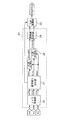
- FIG. 1 is a functional block diagram illustrating a schematic configuration of the distance measuring and imaging apparatus according to the first embodiment.
- FIG. 2 is a schematic configuration diagram showing functions of a CCD type solid-state imaging device.
- FIG. 3 is a diagram for explaining an example of timing for detecting the exposure amount of the distance measurement imaging apparatus according to the first embodiment.
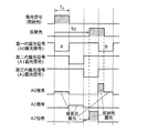
- FIG. 4 is a timing chart of the light emission signal and the exposure signal of the ranging image pickup apparatus according to the first embodiment.
- FIG. 5 is a diagram for explaining an example of timing for detecting the exposure amount of the distance measurement imaging apparatus according to the first embodiment.
- FIG. 6 is a timing chart of the light emission signal and the exposure signal of the ranging image pickup apparatus according to the first embodiment.
- FIG. 7 is a functional block diagram illustrating an example of a schematic configuration of a signal amount comparison unit of the distance image pickup device according to the modification of the first embodiment.
- FIG. 8 is a timing chart of the light emission signal and the exposure signal of the distance measurement imaging apparatus according to the second embodiment.
- FIG. 9 is a timing chart of the light emission signal and the exposure signal of the distance measuring imaging apparatus according to the second embodiment.
- FIG. 10 is a timing chart of the light emission signal and the exposure signal of the distance measurement imaging apparatus according to the second embodiment.
- FIG. 11 is a timing chart of the light emission signal and the exposure signal of the distance measuring apparatus according to the first modification of the second embodiment.
- FIG. 12 is a timing chart of the light emission signal and the exposure signal of the distance measuring imaging apparatus according to the first modification of the second embodiment.
- FIG. 13 is a timing chart of the light emission signal and the exposure signal of the distance measuring imaging apparatus according to the first modification of the second embodiment.
- FIG. 14 is a timing chart of the light emission signal and the exposure signal of the distance measuring imaging apparatus according to the second modification of the second embodiment.
- FIG. 1 is a functional block diagram illustrating an example of a schematic configuration of the distance measuring and imaging apparatus 1 according to the first embodiment.
- the ranging image pickup apparatus 1 includes a light source unit 11, a solid-state image pickup unit 12, a drive control unit 13, a signal amount comparison unit 14, and a TOF calculation unit 15 (distance calculation unit 15).
- the ranging image pickup apparatus 1 includes a light source unit 11, a solid-state image pickup unit 12, a drive control unit 13, a signal amount comparison unit 14, and a TOF calculation unit 15 (distance calculation unit 15).
- the light source unit 11 has a drive circuit, a capacitor, and a light emitting element, and emits light by supplying the charge held in the capacitor to the light emitting diode.
- the light emitting element other light emitting elements such as a laser diode and a light emitting diode (LED) may be used.
- the drive control unit 13 generates a light emission signal for instructing light irradiation to the measurement target (target object OB) and an exposure signal for instructing exposure of reflected light from the target object OB.
- the light source unit 11 irradiates the target object OB with light according to the timing of receiving the light emission signal generated by the drive control unit 13.
- the solid-state imaging unit 12 performs multiple exposures on the region including the target object OB in accordance with the timing indicated by the exposure signal generated by the drive control unit 13, and RAW data (imaging) corresponding to the sum of the multiple exposure amounts. get information.
- the solid-state imaging unit 12 includes a circuit that creates and outputs RAW data such as a camera lens, a solid-state imaging device, and an A / D converter.
- the signal amount comparison unit 14 determines at least the magnitude relationship between the signal amounts in the RAW data received from the solid-state imaging unit 12, and transmits the determination to the TOF calculation unit 15 (distance calculation unit 15).
- the TOF calculation unit 15 (distance calculation unit 15) is based on the RAW data received from the solid-state imaging unit 12 or the signal based on the RAW data output from the solid-state imaging unit 12 received from the signal amount comparison unit 14.
- the TOF signal (distance signal) that is the distance information up to is calculated according to the determination result of the signal amount comparison unit 14 and output.
- the solid-state imaging unit 12 of the distance measuring and imaging device 1 according to the present embodiment is used as a CCD (Charge Coupled Device) type solid-state imaging device.
- CCD Charge Coupled Device
- FIG. 2 is a schematic configuration diagram showing functions of a CCD type solid-state imaging device.
- the CCD solid-state imaging device includes a photodiode 101, a vertical transfer unit 102, a horizontal transfer unit 103, and a signal charge detection unit 104.
- the photodiode 101 converts the received light into electric charges.
- the vertical transfer unit 102 includes a plurality of gates, and sequentially transfers charges read from the photodiode 101 in the vertical direction.
- the horizontal transfer unit 103 sequentially transfers the charges received from the vertical transfer unit 102 as packets by a plurality of gates configured by a plurality of gates.
- the signal charge detection unit 104 sequentially detects the charges received from the horizontal transfer unit, converts them into voltage signals, and outputs them.
- the substrate voltage is controlled according to the exposure signal, the photodiode 101 is exposed during the period when the exposure signal is Low, and the charge generated by the exposure is accumulated in the vertical transfer unit 102.
- FIG. 3 and FIG. 5 are diagrams for explaining an example of the timing for detecting the exposure amount of the ranging image pickup apparatus according to the first embodiment.
- an example is shown in which the number of different signal accumulation means for accumulating signals detected by the same pixel constituting the solid-state imaging unit 12 is three.
- 3A and 5A show examples of timing relationships on one screen where the drive control unit 13 outputs a light emission signal and an exposure signal, respectively.
- 3 (b) and FIG. 5 (b) show the detection timing of the exposure amount A0 in the first light emission exposure period, respectively.
- FIG. 3 (c) and FIG. Each represents the detection timing of the exposure amount A1 in the second light emission exposure period, and (d) in FIG. 3 and (d) in FIG. 5 each represent the detection timing of the exposure amount A2 in the third light emission exposure period. .
- the photodiode 101 in the first light emission exposure period, the photodiode 101 is in a period in which the first exposure signal is Low. And charges generated by the exposure are accumulated in the vertical transfer unit 102. This operation is repeated m times in this embodiment, and when the first light emission exposure period ends, the gate of the vertical transfer unit 102 is controlled to transfer the charge to a packet having no read gate.
- the first light emission exposure period is a period in which the solid-state imaging unit 12 receives the exposure signal through the first delay time and performs exposure with respect to the timing at which the light source unit 11 receives the light emission signal and emits light. It is.
- the length of the first exposure signal period is set to To which is the same as the length of the light emission signal period, and the first delay time is set to zero. That is, the first exposure signal period is set to a period during which the light emission signal is transmitted (high level).
- the second exposure signal is in the Low period. 101 is exposed, and charges generated by the exposure are accumulated in the vertical transfer unit 102. In this embodiment, this operation is repeated m times, and when the second light emission exposure period ends, the gate of the vertical transfer unit 102 is controlled to transfer the charge to a packet having no readout gate.
- the second light emission exposure period is a period for performing exposure by receiving an exposure signal through a second delay time different from the first delay time with respect to the timing at which the solid-state imaging unit 12 receives the light emission signal. is there.
- the length of the second exposure signal period is set to To which is the same as the length of the light emission signal period and the length of the first exposure signal period, and the second delay time is the first delay time 0.
- the first exposure signal period are set to To.
- the photodiode in the third light-emission exposure period, the photodiode is used while the third exposure signal is Low. 101 is exposed, and charges generated by the exposure are accumulated in the vertical transfer unit 102. In this embodiment, this operation is repeated m times, and when the third light emission exposure period ends, the gate of the vertical transfer unit 102 is controlled, and the charge exposed by the first exposure signal is present in the readout gate. Forward as it comes in the packet.
- the third light emission exposure period refers to the exposure by receiving the exposure signal through a third delay time different from the first and second delay times with respect to the timing at which the solid-state imaging unit 12 receives the light emission signal. It is a period to perform.
- the length of the third exposure signal period is set to To which is the same as the length of the light emission signal period and the lengths of the first and second exposure signal periods, and the third delay time is the first delay time.
- the delay time 0, the first exposure signal period To, and the second exposure period To are set to 2 ⁇ To.
- this series of operations is repeated N times in this embodiment, and then the transfer of the vertical transfer unit 102 and the transfer of the horizontal transfer unit 103 are sequentially repeated, and the charge is converted into a voltage signal by the signal charge detection unit 104. And output.
- a plurality of units already configured in the vertical transfer unit 102 as means for accumulating signals obtained in a plurality of exposure periods with different timings of exposure signals for receiving reflected light from the target object OB with respect to the light emission signals. Packets can be used. Therefore, it is not necessary to form additional signal storage means. If the area is the same, the photodiode 101 can be formed larger, the saturation sensitivity can be increased, the maximum received light amount is increased, and high-precision distance measurement is possible. Can be realized.
- CMOS image sensor CMOS solid-state imaging device
- the solid-state imaging device used in the present embodiment is not limited to the CCD image sensor, and a CMOS image sensor (CMOS solid-state imaging device) or the like is considered in consideration of other requirements as a range-finding imaging device. Even when other solid-state imaging devices (image sensors) are used, the same effect (an improvement in distance measurement accuracy by S / N improvement, etc.) can be obtained.
- FIGS. 4 and 6 are timing charts of the light emission signal and the exposure signal of the distance measuring image pickup apparatus according to the first embodiment, respectively.
- 3 (b), (c) and (d), FIG. 4, FIG. 5 (b), (c) and (d), and FIG. 6 show the ranging imaging according to the first embodiment.
- 3 is a diagram illustrating details of the operation of the device 1.
- FIG. More specifically, an example of the timing relationship between the light emission signal generated by the drive control unit 13 and the exposure signal is shown. Of these, FIGS. 4 and 6 show the timings of the light emission signal and the exposure signal on the same sheet in order to make it easier to understand the relationship between the exposure periods at which the timings of the exposure signals for receiving the reflected light are different. Is.
- the number of different signal accumulation means for accumulating signals detected by the same pixel constituting the solid-state imaging unit 12 is three.
- the drive control unit 13 outputs a first exposure signal, a second exposure signal, and a third exposure signal at different timings at which the solid-state imaging unit 12 receives reflected light from the target object OB with respect to the light emission signal.
- the lengths of the first, second, and third exposure signal periods are set to the same TO as the length of the light emission signal period, and the light source unit 11 receives the light emission signal and emits light.
- the delay time of the first exposure signal is set to zero. That is, the first exposure signal period is set to a period during which the light emission signal is transmitted (high level).
- the delay time of the second exposure signal is set to To obtained by adding the first delay time 0 and the first exposure signal period To, and the delay time of the third exposure signal is the second delay time.
- the time To and the second exposure period To are set to 2 ⁇ To. Therefore, the exposure amount of the background light becomes equal in the first, second and third exposure signal periods.
- FIG. 3 and (a) in FIG. 5 show examples of timing relationships in one screen of the light emission signal and the first, second and third exposure signals.
- the repetition of the light emission signal and the exposure signal in the first, second, and third light emission exposure periods is m times, and a series of timings is set as one set, and this is repeatedly output N times, The accumulated exposure signal is output. Therefore, the sum of the exposure amount a0 based on the first exposure signal is A0, the sum of the exposure amount a1 based on the second exposure signal is A1, and the sum of the exposure amount a2 based on the third exposure signal is A2.
- the delay Td due to the optical path of the reflected light from the target object OB with respect to the light emission signal timing (irradiation light) is a value obtained by adding the first delay time 0 and the first exposure signal period To ( That is, the case where it is less than To) is shown.
- the exposure is performed so as to include all of the reflected light from the target object OB in a period obtained by adding the first exposure signal period and the second exposure signal period. Further, the exposure amount in the second exposure signal period increases as the delay Td with respect to the light emission signal timing of the reflected light from the target object OB increases.
- the third exposure signal period only background light is exposed.
- the signal amount comparison unit 14 compares the total exposure amount A0 based on the first exposure signal with the total exposure amount A2 based on the third exposure signal, and makes a determination as shown in the following equation 1.
- the signal amount comparison unit 14 transmits the determination result of Expression 1 to the TOF calculation unit 15.
- the TOF calculation unit 15 can calculate the distance L by performing the calculation of Expression 2 below.
- the delay Td due to the optical path of the reflected light from the target object OB with respect to the light emission signal timing (irradiation light) is a value obtained by adding the first delay time 0 and the first exposure signal period To ( That is, the case of To) or more is shown.
- the exposure is performed so as to include all of the reflected light from the target object OB in a period obtained by adding the second exposure signal period and the third exposure signal period.
- the exposure amount in the third exposure signal period increases as the delay Td with respect to the light emission signal timing of the reflected light from the target object OB increases. Further, only the background light is exposed in the first exposure signal period.
- the signal amount comparison unit 14 compares the sum A0 of the exposure amount based on the first exposure signal with the sum A2 of the exposure amount based on the third exposure signal, and determines as in the following Expression 3.
- the signal amount comparison unit 14 transmits the determination result of Expression 3 to the TOF calculation unit 15.
- the TOF calculation unit 15 can calculate the distance L by performing the calculation of Expression 4 below.
- the exposure period is a period in which the reflected light from the target object OB is exposed with respect to the timing of the light emission signal. Then, by changing the expression of the TOF calculation according to the result of comparing the magnitude relations of the signal amounts of different signal accumulation means, the exposure period is extended while performing background light removal.
- the distance measurement range (limit) is not limited to c ⁇ To / 2, but doubles to 2 ⁇ (c ⁇ To / 2). Thereby, without increasing the pulse width TO of the light source, the distance measurement range can be expanded to at least one of the far side, the near side, or both by setting the first delay time. Therefore, it is possible to realize a ranging imaging apparatus having a high accuracy and a wide ranging range.
- FIG. 7 is a functional block diagram illustrating an example of a schematic configuration of a signal amount comparison unit of the distance image pickup device according to the modification of the first embodiment.
- the signal amount comparison unit 24 includes a noise removal unit 26, a signal distribution unit 27, a background light removal unit 28, and an abnormal value determination unit 29.
- the noise removing unit 26 removes noise from the RAW data received from the solid-state imaging unit 12.
- the signal distribution unit 27 includes only a signal including a plurality of reflected lights and a background light based on the magnitude relation of signal amounts between signals stored in a plurality of different signal storage units in the RAW data after noise removal received from the noise removal unit 26. And the determination result of the magnitude relation of the signal amount is transmitted to the TOF calculation unit 25 (distance calculation unit 25).
- the background light removal unit 28 removes the background light signal by subtracting the signal of only the background light from the signal including the plurality of reflected lights received from the signal distribution unit 27.
- the abnormal value determination unit 29 determines an abnormal value from the signal obtained by removing the plurality of background lights received from the background light removal unit 28 and transmits the result to the TOF calculation unit 25.
- the noise removal unit 26 includes a total exposure amount A0 based on the first exposure signal, a total exposure amount A1 based on the second exposure signal, and a total exposure amount based on the third exposure signal in the RAW data received from the solid-state imaging unit 12.
- Each noise of A2 is removed, and each exposure amount from which the noise is removed is transmitted to the signal distribution unit 27 as A0nr, A1nr, and A2nr.
- the signal distribution unit 27 is a value obtained by adding the first delay time 0 and the first exposure signal period to the delay Td due to the optical path of the reflected light from the target object OB with respect to the light emission signal timing (irradiation light) (that is, TO If it is less than), it is determined as in the following formula 5.
- the signal distribution unit 27 sets the exposure amount to decrease as S0nr, the increase as S1nr, and the exposure amount of only the background light as BGnr as the delay Td with respect to the light emission signal timing of the reflected light from the target object OB increases.
- the signal is distributed as shown in the following Expression 6 and transmitted to the background light removal unit 28.
- the determination result J 0 is transmitted to the TOF calculation unit 25.
- the delay Td due to the optical path of the reflected light from the target object OB with respect to the light emission signal timing (irradiation light) is not less than the value obtained by adding the first delay time 0 and the first exposure signal period (ie, To).
- the signal distribution unit 27 performs determination as in the following Expression 7, distributes the signal as in the following Expression 8, and transmits the signal to the background light removal unit 28.
- the background light removing unit 28 removes the background light, performs the following Expression 9 and transmits it to the abnormal value determining unit 29.
- the abnormal value determination unit 29 determines the signal amounts of S0subBG and S1subBG received from the background light removal unit 28. When the target object OB is out of the measurement range, the total exposure amount A0 based on the first exposure signal, the total exposure amount A1 based on the second exposure signal, and the total exposure amount A2 based on the third exposure signal are almost the same. It becomes signal amount. At this time, if the signal amounts of S0subBG and S1subBG are very close to zero, the abnormal value determination unit 29 determines that the abnormal value is outside the measurement range and transmits the abnormal value to the TOF calculation unit 25. And S1subBG are transmitted to the TOF calculation unit 25.
- the TOF calculation unit 25 can calculate the distance L by performing the calculation of Expression 10 below.
- the distance measurement range (limit) is not limited to c ⁇ To / 2, and not only doubles to 2 ⁇ (c ⁇ To / 2), but also compares the amount of signal between signals from which noise has been removed. Therefore, erroneous determination can be prevented. Therefore, it is possible to realize a ranging imaging device with higher accuracy and a wider ranging range.
- the signal amount of multiple signals from which background light has been removed is determined, it is observed that the signal amount of all of the multiple signals from which background light has been removed is very close to zero when the measurement object is outside the measurement range. The As a result, it is possible to easily determine the outside of the distance measurement range, and it is possible to realize a distance measurement imaging device with a higher accuracy and a wider distance measurement range.
- FIG. 9 and FIG. 10 are timing charts of the light emission signal and the exposure signal of the distance measuring and imaging apparatus 1 according to the second embodiment, respectively.
- an example of the timing relationship between the light emission signal and the exposure signal generated by the drive control unit 13 is shown, and it is easy to understand the relationship between a plurality of exposure periods with different timings of the exposure signal that receives reflected light.
- each timing of the light emission signal and the exposure signal is shown on the same sheet.
- an example is shown in which the number of different signal accumulating units that accumulate signals detected by the same pixel constituting the solid-state imaging unit 12 is three.
- the drive control unit 13 outputs a first exposure signal, a second exposure signal, and a third exposure signal at different timings at which the solid-state imaging unit 12 receives reflected light from the target object OB with respect to the light emission signal.
- the length of the exposure signal period of the first exposure signal is set to the same To as the length of the light emission signal period.
- the first exposure signal includes the first exposure signal A having an exposure period in which the delay time is set to 0 with respect to the timing at which the light source unit 11 receives the light emission signal and emits light, and the third exposure time. It is composed of two exposure signals, a first exposure signal B having an exposure period set to 3 * To, which is obtained by adding a signal delay time 2 * To and a third exposure period To.
- the lengths of the second and third exposure signal periods are set to the same To as the length of the light emission signal period.
- the delay time of the second exposure signal is set to To obtained by adding the delay time 0 of the first exposure signal A and the exposure period (To) of the first exposure signal A.
- the delay time of the third exposure signal is set to 2 ⁇ To obtained by adding the delay time To of the second exposure signal and the second exposure signal period To.
- the exposure amount of the background light is equal in the second and third exposure signal periods, and doubles in the first exposure signal period.
- the delay Td due to the optical path of the reflected light from the target object OB with respect to the light emission signal timing is the delay time 0 of the first exposure signal A and the first exposure signal A.
- the case where the exposure period To is less than the added value To is shown.
- the exposure is performed so as to include all of the reflected light from the target object OB in the period obtained by adding the exposure period of the first exposure signal A and the second exposure signal period.
- the exposure amount in the second exposure signal period increases as the delay Td of the reflected light from the target object OB with respect to the light emission signal timing increases.
- the third exposure signal period only background light is exposed.
- the signal amount comparison unit 14 compares the total exposure amount A0 based on the first exposure signal with the total exposure amount A1 based on the second exposure signal and the total exposure amount A2 based on the third exposure signal, Judgment is made as shown in Equation 11 below.
- the signal amount comparison unit 14 transmits the determination result of Expression 11 to the TOF calculation unit 15.
- the distance L can be calculated by performing the calculation of Expression 12 below.
- the delay Td due to the optical path of the reflected light from the target object OB with respect to the emission signal timing (irradiation light) is added by the delay time 0 of the first exposure signal A and the exposure period To of the first exposure signal A.
- a case is shown in which the delay time To of the second exposure signal and the second exposure signal period To are less than the value 2 ⁇ To, which is equal to or greater than the set value To.
- the exposure is performed so as to include all of the reflected light from the target object OB in a period obtained by adding the second exposure signal period and the third exposure signal period. Further, the exposure amount in the third exposure signal period increases as the delay Td with respect to the light emission signal timing of the reflected light from the target object OB increases. Further, only the background light is exposed in the first exposure signal period.
- the signal amount comparison unit 14 compares the total exposure amount A0 based on the first exposure signal with the total exposure amount A1 based on the second exposure signal and the total exposure amount A2 based on the third exposure signal, Judgment is made as shown in Equation 13 below.
- the signal amount comparison unit 14 transmits the determination result of Expression 13 to the TOF calculation unit 15.
- the TOF calculation unit 15 can calculate the distance L by performing the calculation of Expression 14 below.
- the delay Td due to the optical path of the reflected light from the target object OB with respect to the emission signal timing is a value 2 obtained by adding the delay time To of the second exposure signal and the second exposure signal period To.
- the exposure is performed so as to include all of the reflected light from the target object OB in a period in which the third exposure signal period and the first exposure signal period A are added.
- the exposure amount during the exposure period of the first exposure signal B increases as the delay Td of the reflected light from the target object OB with respect to the light emission signal timing increases.
- the second exposure signal period only background light is exposed.
- the signal amount comparison unit 14 compares the total exposure amount A0 based on the first exposure signal with the total exposure amount A1 based on the second exposure signal and the total exposure amount A2 based on the third exposure signal, Determination is made as shown in Equation 15 below.
- the signal amount comparison unit 14 transmits the determination result of Expression 15 to the TOF calculation unit 15.
- the TOF calculation unit 15 can calculate the distance L by performing the calculation of Expression 16 below.
- the exposure period is a period in which the reflected light from the target object OB is exposed with respect to the timing of the light emission signal.
- at least one identical signal storage means of the signal storage means stores signals exposed at a plurality of different timings with respect to the light emission signal. Then, by changing the expression of the TOF calculation according to the comparison result of the signal amounts of a plurality of different signal storage means, the exposure period is further extended while performing background light removal without increasing the signal storage means.
- the distance measuring range is not limited to c ⁇ To / 2, but is three times as large as 3 ⁇ (c ⁇ To / 2).
- the distance measurement range can be further expanded to at least one of the far side, the near side, or both by setting the first delay time. Therefore, it is possible to realize a ranging imaging apparatus having a high accuracy and a wide ranging range.
- Modification 1 of Embodiment 2 11, 12, and 13 are timing charts of the light emission signal and the exposure signal of the ranging image pickup apparatus 1 according to the first modification of the second embodiment, respectively.
- an example of the timing relationship between the light emission signal and the exposure signal generated by the drive control unit 13 is shown, and it is easy to understand the relationship between a plurality of exposure periods with different timings of the exposure signal that receives reflected light.
- each timing of the light emission signal and the exposure signal is shown on the same sheet.
- an example is shown in which the number of different signal accumulating units that accumulate signals detected by the same pixel constituting the solid-state imaging unit 12 is three.
- the drive control unit 13 outputs a first exposure signal, a second exposure signal, and a third exposure signal at different timings at which the solid-state imaging unit 12 receives reflected light from the target object OB with respect to the light emission signal.
- the length of the exposure signal period of the first exposure signal is set to the same To as the length of the light emission signal period.
- the first exposure signal includes the first exposure signal A having an exposure period in which the delay time is set to 0 with respect to the timing at which the light source unit 11 receives the light emission signal and emits light, and the third exposure time. It is composed of two exposure signals, a first exposure signal B having an exposure period set to 3 ⁇ To, which is obtained by adding a delay time 2 ⁇ To of the signal A and an exposure period To of the third exposure signal A. Has been.
- the length of the exposure signal period of the second exposure signal is set to the same To as the length of the light emission signal period.
- the second exposure signal is composed of two exposure signals of a second exposure signal A and a second exposure signal B.
- the second exposure signal A has an exposure period set to To that is obtained by adding the delay time 0 of the first exposure signal A and the exposure period To of the first exposure signal A.
- the second exposure signal B has an exposure period whose delay time is set to be longer than 4 * To obtained by adding the delay time 3 * To of the first exposure signal B and the exposure period To of the first exposure signal B.
- the length of the exposure signal period of the third exposure signal is set to To which is the same as the length of the light emission signal period.
- the third exposure signal is composed of two exposure signals of a third exposure signal A and a third exposure signal B.
- the third exposure signal A has an exposure period set to 2 ⁇ To, which is the sum of the delay time To of the second exposure signal A and the exposure period To of the second exposure signal A.
- the third exposure signal B has an exposure period whose delay time is set to be longer than 4 * To obtained by adding the delay time 3 * To of the first exposure signal B and the exposure period To of the first exposure signal B.
- the exposure amount of the background light becomes equal in the first, second and third exposure signal periods.
- the delay Td due to the optical path of the reflected light from the target object OB with respect to the emission signal timing (irradiation light) is the delay time 0 of the first exposure signal A and the first exposure signal A.
- the case where the exposure period To is less than the added value To is shown.
- the exposure is performed so as to include all the reflected light from the target object OB in a period obtained by adding the exposure period of the first exposure signal A and the exposure period of the second exposure signal A. Further, the exposure amount of the second exposure signal A during the exposure period increases as the delay Td of the reflected light from the target object OB and the like with respect to the light emission signal timing increases.
- the third exposure signal period only background light is exposed.
- the signal amount comparison unit 14 compares the total exposure amount A0 based on the first exposure signal with the total exposure amount A1 based on the second exposure signal and the total exposure amount A2 based on the third exposure signal, Judgment is made as shown in Equation 17 below.
- the signal amount comparison unit 14 transmits the determination result of Expression 17 to the TOF calculation unit 15.
- the distance L can be calculated by performing the calculation of Expression 18 below.
- the delay Td due to the optical path of the reflected light from the target object OB with respect to the emission signal timing (irradiation light) is added by the delay time 0 of the first exposure signal A and the exposure period To of the first exposure signal A.
- a case is shown in which the delay time To of the second exposure signal A and the exposure period To of the second exposure signal A are less than the value 2 ⁇ To, which is equal to or greater than the value To.
- the exposure is performed so as to include all of the reflected light from the target object OB in a period obtained by adding the exposure period of the second exposure signal A and the exposure period of the third exposure signal A.
- the exposure amount of the third exposure signal A during the exposure period increases as the delay Td of the reflected light from the target object OB increases with respect to the light emission signal timing. Further, only the background light is exposed in the first exposure signal period.
- the signal amount comparison unit 14 compares the total exposure amount A0 based on the first exposure signal with the total exposure amount A1 based on the second exposure signal and the total exposure amount A2 based on the third exposure signal, Determination is made as shown in Equation 19 below.
- the signal amount comparison unit 14 transmits the determination result of Expression 19 to the TOF calculation unit 15.
- the TOF calculation unit 15 can calculate the distance L by performing the calculation of Expression 20 below.
- the delay Td due to the optical path of the reflected light from the target object OB with respect to the emission signal timing is a value 2 obtained by adding the delay time To of the second exposure signal and the second exposure signal period To.
- the exposure is performed so as to include all of the reflected light from the target object OB in a period in which the exposure period of the third exposure signal A and the exposure period of the first exposure signal B are added. Further, the exposure amount during the exposure period of the first exposure signal B increases as the delay Td of the reflected light from the target object OB with respect to the light emission signal timing increases. In the second exposure signal period, only background light is exposed.
- the signal amount comparison unit 14 compares the total exposure amount A0 based on the first exposure signal with the total exposure amount A1 based on the second exposure signal and the total exposure amount A2 based on the third exposure signal, Judgment is made as shown in Equation 21 below.
- the signal amount comparison unit 14 transmits the determination result of Expression 21 to the TOF calculation unit 15.
- the TOF calculation unit 15 can calculate the distance L by performing the calculation of Expression 22 below.
- the exposure period is a period in which the reflected light from the target object OB is exposed with respect to the timing of the light emission signal.
- the same signal storage means stores the signals exposed at a plurality of different timings with respect to the light emission signal, so that the exposure amount of the background light becomes equal, and the plurality of different signal storage means It is easier and more accurate to compare the magnitude relations of the signal amounts. Thereby, by changing the expression of the TOF calculation according to the comparison result, the exposure period is further extended while executing the background light removal without increasing the signal accumulation means.
- the distance measuring range is not limited to c ⁇ To / 2, but is three times as large as 3 ⁇ (c ⁇ To / 2).
- the distance measurement range can be further expanded to at least one of the far side, the near side, or both by setting the first delay time. Therefore, it is possible to realize a ranging imaging apparatus having a high accuracy and a wide ranging range.
- FIG. 14 is a timing chart of the light emission signal and the exposure signal of the distance measurement imaging apparatus 1 according to the second modification of the second embodiment. Specifically, an example of the timing relationship between the light emission signal and the exposure signal generated by the drive control unit 13 is shown, and it is easy to understand the relationship between a plurality of exposure periods with different timings of the exposure signal that receives reflected light. In addition, each timing of the light emission signal and the exposure signal is shown on the same sheet. In the present embodiment, an example is shown in which the number of different signal accumulating units that accumulate signals detected by the same pixel constituting the solid-state imaging unit 12 is four.
- the drive control unit 13 has a first exposure signal, a second exposure signal, a third exposure signal, and a fourth exposure signal at different timings at which the solid-state imaging unit 12 receives reflected light from the target object OB with respect to the light emission signal.
- An exposure signal is output.
- the length of each exposure signal period of the first exposure signal is set to To which is the same as the length of the light emission signal period.
- the first exposure signal includes a first exposure signal A having an exposure period in which a delay time is set to 0 with respect to a timing at which the light source unit 11 receives the light emission signal and emits light, and a fourth exposure time with a delay time. It consists of two exposure signals: a delay time 3 ⁇ To of the signal A and an exposure period To of the fourth exposure signal A, or a first exposure signal B having an exposure period set to 4 ⁇ To. ing.
- the length of each exposure signal period of the second exposure signal is set to To which is the same as the length of the light emission signal period.
- the second exposure signal is composed of two exposure signals of a second exposure signal A and a second exposure signal B.
- the second exposure signal A has an exposure period set to To that is obtained by adding the delay time 0 of the first exposure signal A and the exposure period To of the first exposure signal A.
- the second exposure signal B has an exposure period whose delay time is set larger than 6 * To, which is obtained by adding the delay time 5 * To of the third exposure signal B and the exposure period To of the third exposure signal B.
- the length of each exposure signal period of the third exposure signal is set to To which is the same as the length of the light emission signal period.
- the third exposure signal is composed of two exposure signals of a third exposure signal A and a third exposure signal B.
- the third exposure signal A has an exposure period set to 2 ⁇ To, which is the sum of the delay time To of the second exposure signal A and the exposure period To of the second exposure signal A.
- the third exposure signal B has an exposure period set to 5 ⁇ To, which is the sum of the delay time 4 ⁇ To of the first exposure signal B and the exposure period To of the first exposure signal B. .
- the length of each exposure signal period of the fourth exposure signal is set to To which is the same as the length of the light emission signal period.
- the fourth exposure signal is composed of two exposure signals of a fourth exposure signal A and a fourth exposure signal B.
- the fourth exposure signal A has an exposure period set to 3 ⁇ To, which is the sum of the delay time 2 ⁇ To of the third exposure signal A and the exposure period To of the third exposure signal A.
- the fourth exposure signal B has an exposure period in which the delay time is set to be longer than 6 * To obtained by adding the delay time 5 * To of the third exposure signal B and the exposure period To of the third exposure signal B.
- the exposure amount of the background light becomes equal in the first, second, third and fourth exposure signal periods.
- the signal amount comparison unit 14 calculates the total exposure amount A0 based on the first exposure signal, the total exposure amount A1 based on the second exposure signal, the total exposure amount A2 based on the third exposure signal, and the fourth exposure.
- the total exposure amount A3 based on the signal is compared, and a determination is made as shown in Expression 23 below.
- the signal amount comparison unit 14 transmits the determination result of Expression 23 to the TOF calculation unit 15.
- the distance L can be calculated by performing the calculation of Expression 24 below.
- the background light exposure amount BG may be any of A2, A3, and (A2 + A3) / 2.
- the exposure period of the second exposure signal A The exposure is performed so as to include all of the reflected light from the target object OB in a period obtained by adding the exposure periods of the three exposure signals A. Further, the exposure amount of the third exposure signal A during the exposure period increases as the delay Td of the reflected light from the target object OB increases with respect to the light emission signal timing. Further, only the background light is exposed in the first exposure signal period and the fourth exposure signal period.
- the signal amount comparison unit 14 calculates the total exposure amount A0 based on the first exposure signal, the total exposure amount A1 based on the second exposure signal, the total exposure amount A2 based on the third exposure signal, and the fourth exposure.
- the total exposure amount A3 based on the signal is compared, and a determination is made as in the following Expression 25.
- the signal amount comparison unit 14 transmits the determination result of Expression 25 to the TOF calculation unit 15.
- the TOF calculation unit 15 can calculate the distance L by performing the calculation of Expression 26 below.
- the background light exposure amount BG may be any of A0, A3, and (A0 + A3) / 2.
- the delay time Td due to the optical path of the reflected light from the target object OB with respect to the light emission signal timing is a value 2 obtained by adding the delay time To of the second exposure signal A and the exposure period To of the second exposure signal A If the delay time 2 ⁇ To of the third exposure signal A and the exposure period To of the third exposure signal A are less than 3 ⁇ To, which is greater than or equal to ⁇ To, the third exposure signal A
- the exposure is performed so as to include all of the reflected light from the target object OB in a period obtained by adding the exposure period of 4 and the exposure period of the fourth exposure signal A.
- the exposure amount in the fourth exposure signal A increases as the delay Td of the reflected light from the target object OB with respect to the light emission signal timing increases. Further, only the background light is exposed in the first exposure signal period and the second exposure signal period.
- the signal amount comparison unit 14 calculates the total exposure amount A0 based on the first exposure signal, the total exposure amount A1 based on the second exposure signal, the total exposure amount A2 based on the third exposure signal, and the fourth exposure.
- the total exposure amount A3 based on the signal is compared, and a determination is made as shown in Expression 27 below.
- the signal amount comparison unit 14 transmits the determination result of Expression 27 to the TOF calculation unit 15.
- the TOF calculation unit 15 can calculate the distance L by performing the calculation of Expression 28 below.
- the background light exposure amount BG may be any of A0, A1, and (A0 + A1) / 2.
- the delay Td due to the optical path of the reflected light from the target object OB with respect to the light emission signal timing is added to the delay time 2 ⁇ To of the third exposure signal A and the exposure period To of the third exposure signal A. If the value is 3 ⁇ To or more and is less than the value 4 ⁇ To obtained by adding the delay time 3 ⁇ To of the fourth exposure signal A and the exposure period To of the fourth exposure signal A, the fourth exposure is performed.
- the exposure is performed so as to include all the reflected light from the target object OB in a period in which the exposure period of the signal A and the exposure period of the first exposure signal B are added. Further, the exposure amount during the exposure period of the first exposure signal B increases as the delay Td of the reflected light from the target object OB with respect to the light emission signal timing increases. Further, only the background light is exposed in the second exposure signal period and the third exposure signal period.
- the signal amount comparison unit 14 calculates the total exposure amount A0 based on the first exposure signal, the total exposure amount A1 based on the second exposure signal, the total exposure amount A2 based on the third exposure signal, and the fourth exposure.
- the total exposure amount A3 based on the signal is compared, and a determination is made as shown in Expression 29 below.
- the signal amount comparison unit 14 transmits the determination result of Expression 29 to the TOF calculation unit 15.
- the TOF calculation unit 15 can calculate the distance L by performing the calculation of Expression 30 below.
- the background light exposure amount BG may be any of A1, A2, and (A1 + A2) / 2.
- the delay Td due to the optical path of the reflected light from the target object OB with respect to the light emission signal timing is obtained by adding the delay time 3 ⁇ To of the fourth exposure signal A and the exposure period To of the fourth exposure signal A.
- the reflected light from the target object OB is included in the period obtained by adding the exposure period of the first exposure signal B and the exposure period of the third exposure signal B. Exposed.
- the exposure amount of the third exposure signal B during the exposure period increases as the delay Td of the reflected light from the target object OB increases with respect to the light emission signal timing. Further, only the background light is exposed in the second exposure signal period and the fourth exposure signal period.
- the timing chart of FIG. 14 shows this case.
- the signal amount comparison unit 14 calculates the total exposure amount A0 based on the first exposure signal, the total exposure amount A1 based on the second exposure signal, the total exposure amount A2 based on the third exposure signal, and the fourth exposure.
- the total exposure amount A3 based on the signal is compared, and a determination is made as shown in Expression 31 below.
- the signal amount comparison unit 14 transmits the determination result of Expression 31 to the TOF calculation unit 15.
- the TOF calculation unit 15 can calculate the distance L by performing the calculation of Expression 32 below.
- the background light exposure amount BG may be any of A1, A3, and (A1 + A3) / 2.
- the exposure period is a period in which the reflected light from the target object OB is exposed with respect to the timing of the light emission signal.
- the same signal storage means stores the signals exposed at a plurality of different timings with respect to the light emission signal, so that the exposure amount of the background light becomes equal, and the plurality of different signal storage means It is easier and more accurate to compare the magnitude relations of the signal amounts. Thereby, by changing the expression of the TOF calculation according to the comparison result, the exposure period is further extended while executing the background light removal without increasing the signal accumulation means.
- the distance measurement range is not limited to 2 ⁇ (c ⁇ To / 2) when one of the signal storage means is used exclusively for exposure of background light, and 5 ⁇ (c ⁇ To / 2). And spread 2.5 times.
- the distance measurement range can be further expanded to at least one of the far side, the near side, or both by setting the first delay time. Therefore, it is possible to realize a ranging imaging apparatus having a high accuracy and a wide ranging range.
- the ranging imaging device has been described.
- the configuration of the ranging imaging device according to the present disclosure is not limited to the ranging imaging device that measures the distance based on the distance information, and other physical quantities (eg, shape)
- the present invention can also be applied to a physical quantity detection device that accurately detects temperature, radiation concentration, and the like, and an imaging device that accurately describes captured data.
- the distance measuring and imaging apparatus 1 As described above with reference to the drawings, the distance measuring and imaging apparatus 1 according to the embodiment of the present invention generates a light emission signal instructing light irradiation and an exposure signal instructing exposure of reflected light. Then, the light source unit 11 that irradiates light according to the timing indicated by the light emission signal, and the imaging information corresponding to the exposure amount of the exposure performed by exposing the region including the target object OB according to the timing indicated by the exposure signal.
- the solid-state imaging unit 12 that generates RAW data, the signal amount comparison unit 14 that determines the magnitude relationship of the signal amount in the RAW data, and the target object OB based on the determination result of the magnitude relationship of the signal amount by the signal amount comparison unit 14 And a TOF calculation unit 15 that generates and outputs a distance signal indicating the distance.
- the solid-state imaging unit 12 includes a plurality of different signal storage areas for storing signals detected by the same pixel, and each of the different signal storage areas is transmitted from the target object OB with respect to the timing of the light emission signal.
- the signal amount comparison unit 14 determines the magnitude relationship between the signal amounts of a plurality of signals accumulated in different signal accumulation regions. Then, the TOF calculation unit 15 receives the RAW data from the solid-state imaging unit 12 or the signal amount comparison unit 14, and calculates the distance to the target object OB using the calculation formula selected according to the determination result of the signal amount magnitude relationship. Thus, a distance signal is generated and output.
- the plurality of different signal storage areas allow background light removal without being used exclusively for background light, and exposure signals that expose the reflected light from the target object OB with respect to the timing of the emission signal. Are used to store signals exposed during different exposure periods. This extends the exposure period and extends the period during which the reflected light can be captured, so that the range can be expanded to at least one or both of the far side and near side without increasing the pulse width of the light source. Can do.
- the solid-state imaging unit 12 performs multiple exposures on the region including the target object OB according to the timing indicated by the exposure signal, and RAW data that is imaging information corresponding to the sum of the exposure amounts of the multiple exposures. May be generated.
- At least one same signal storage area may store a plurality of signals exposed at a plurality of different timings of the exposure signal with respect to the light emission signal.
- the signal amount comparison unit 14 includes a noise removal unit 26 that removes noise from the RAW data received from the solid-state imaging unit 12, and a plurality of different signal accumulation regions in the RAW data after noise removal received from the noise removal unit 26.
- a signal distribution that distributes a signal including a plurality of reflected lights and a signal of only background light based on the magnitude relation of the accumulated signal quantities of the plurality of signals and transmits a determination result of the magnitude relation of the signal quantities to the TOF calculation unit 25 27, a background light removing unit 28 for removing a background light signal by subtracting a signal of only background light from a signal including a plurality of reflected lights received from the signal distribution unit 27, and a background light removing unit 28 for background light.
- the present invention can be realized not only as a distance measuring and imaging apparatus having such a characteristic configuration but also as a distance measuring method of the distance measuring and imaging apparatus.
- the distance measuring method of the distance measuring and imaging apparatus corresponds to the timing of the light emission signal corresponding to each of a plurality of different signal storage areas in which the solid-state imaging unit 12 stores signals detected by the same pixel.
- a plurality of signals exposed in exposure periods having different exposure signal timings are accumulated, and the signal amount comparison unit 14 determines the magnitude relationship of the signal amounts of the signals accumulated in the plurality of different signal accumulation regions, and the TOF calculation unit 15 selects an arithmetic expression for calculating the distance to the target object OB according to the determination result of the signal amount comparison unit 14, and calculates the distance to the target object OB using the selection expression, thereby obtaining the distance signal.
- a plurality of different signal accumulation regions enable background light removal without being used exclusively for background light, and the timing of the exposure signal that exposes the reflected light from the target object OB with respect to the timing of the emission signal. It is used to store signals exposed during different exposure periods. This extends the exposure period and extends the period during which the reflected light can be captured, so that the range can be expanded to at least one or both of the far side and near side without increasing the pulse width of the light source. Can do.
- the present invention can be realized not only as a ranging imaging device and a ranging method having such a characteristic configuration, but also as a solid-state imaging device using the solid-state imaging unit 12 used in the ranging imaging device. can do. That is, the solid-state imaging used in the distance-measuring imaging device 1 including the drive control unit 13, the light source unit 11, the solid-state imaging device that is the solid-state imaging unit 12, the signal amount comparison unit 14, and the TOF calculation unit 15.
- Each of the plurality of different signal accumulation regions is an apparatus for accumulating signals exposed in exposure periods having different exposure signal timings for instructing exposure of reflected light from the target object OB with respect to the timing of the light emission signal. It is characterized by.
- the plurality of different signal storage areas allow background light removal without being used exclusively for background light, and exposure signals that expose the reflected light from the target object OB with respect to the timing of the emission signal. Are used to store signals exposed during different exposure periods. This extends the exposure period and extends the period during which the reflected light can be captured, so that the range can be expanded to at least one or both of the far side and near side without increasing the pulse width of the light source. Can do.
- the solid-state imaging device may be a CCD type solid-state imaging device.
- a plurality of packets already configured in the vertical transfer unit can be used as an area for accumulating signals obtained in a plurality of different exposure periods. Therefore, it is not necessary to form additional signal accumulating means, and if the area is the same, the photodiode can be formed larger, the saturation sensitivity can be increased, the maximum received light amount is increased, and high-precision ranging is achieved. realizable.
- an operation of collectively resetting a plurality of photodiodes, so-called global reset can be performed, and further accurate ranging can be realized.
- the ranging imaging device of this indication has been explained based on the above-mentioned embodiment, the ranging imaging device of this indication is not limited to the above-mentioned embodiment.
- a TOF (time of flight) method that performs distance measurement using a flight time in which light reciprocates to a measurement target is used.
- the present invention also includes a case of using other methods for distance measurement.
- the distance measuring and imaging apparatus can realize highly accurate three-dimensional measurement of an object to be measured without depending on the surrounding environment, and is useful for, for example, three-dimensional measurement of a person, a building, and the like.
Landscapes
- Engineering & Computer Science (AREA)
- Physics & Mathematics (AREA)
- General Physics & Mathematics (AREA)
- Remote Sensing (AREA)
- Radar, Positioning & Navigation (AREA)
- Computer Networks & Wireless Communication (AREA)
- Electromagnetism (AREA)
- Signal Processing (AREA)
- Multimedia (AREA)
- Optical Radar Systems And Details Thereof (AREA)
- Studio Devices (AREA)
- Transforming Light Signals Into Electric Signals (AREA)
- Measurement Of Optical Distance (AREA)
Abstract
L'invention concerne un dispositif d'imagerie de mesure de distance (1) qui comprend une unité de source de lumière (11) qui émet de la lumière en fonction d'une synchronisation d'un signal d'émission de lumière ; une unité d'imagerie à semi-conducteurs (12) qui provoque l'exposition d'un objet cible OB à la lumière en fonction d'une synchronisation d'un signal d'exposition, et génère des données brutes (RAW) en fonction du niveau d'exposition résultant de l'exposition à la lumière ; une unité de comparaison de niveau de signal (14) qui détermine la relation d'amplitude du niveau de signal dans les données brutes ; et une unité de calcul de distance (15) qui génère et délivre en sortie un signal de distance sur la base du résultat de détermination concernant la relation d'amplitude du niveau de signal. L'unité d'imagerie à semi-conducteurs (12) accumule, sur de multiples régions d'accumulation de signal différentes sur chacune desquelles des signaux détectés dans un seul pixel sont accumulés, des signaux utilisés pour l'exposition pendant des périodes d'exposition ayant différentes synchronisations de signal d'exposition. L'unité de comparaison de niveau de signal (14) détermine la relation d'amplitude du niveau de signal de multiples signaux accumulés sur les multiples régions d'accumulation de signal différentes. L'unité de calcul de distance (15) calcule la distance à l'objet cible OB en utilisant une formule de calcul sélectionnée en fonction du résultat de la détermination.
Priority Applications (4)
| Application Number | Priority Date | Filing Date | Title |
|---|---|---|---|
| JP2017520212A JP6676866B2 (ja) | 2015-05-28 | 2016-05-10 | 測距撮像装置及び固体撮像素子 |
| CN201680029331.5A CN107615093B (zh) | 2015-05-28 | 2016-05-10 | 测距摄像装置、其测距方法以及固体摄像装置 |
| US15/801,111 US10903254B2 (en) | 2015-05-28 | 2017-11-01 | Distance-measuring imaging device, distance measuring method of distance-measuring imaging device, and solid-state imaging device |
| US17/133,617 US11769775B2 (en) | 2015-05-28 | 2020-12-23 | Distance-measuring imaging device, distance measuring method of distance-measuring imaging device, and solid-state imaging device |
Applications Claiming Priority (2)
| Application Number | Priority Date | Filing Date | Title |
|---|---|---|---|
| JP2015-108867 | 2015-05-28 | ||
| JP2015108867 | 2015-05-28 |
Related Child Applications (1)
| Application Number | Title | Priority Date | Filing Date |
|---|---|---|---|
| US15/801,111 Continuation US10903254B2 (en) | 2015-05-28 | 2017-11-01 | Distance-measuring imaging device, distance measuring method of distance-measuring imaging device, and solid-state imaging device |
Publications (1)
| Publication Number | Publication Date |
|---|---|
| WO2016189808A1 true WO2016189808A1 (fr) | 2016-12-01 |
Family
ID=57393833
Family Applications (1)
| Application Number | Title | Priority Date | Filing Date |
|---|---|---|---|
| PCT/JP2016/002297 Ceased WO2016189808A1 (fr) | 2015-05-28 | 2016-05-10 | Dispositif d'imagerie de mesure de distance, procédé de mesure de distance l'utilisant, et dispositif d'imagerie à semi-conducteurs |
Country Status (4)
| Country | Link |
|---|---|
| US (2) | US10903254B2 (fr) |
| JP (1) | JP6676866B2 (fr) |
| CN (1) | CN107615093B (fr) |
| WO (1) | WO2016189808A1 (fr) |
Cited By (6)
| Publication number | Priority date | Publication date | Assignee | Title |
|---|---|---|---|---|
| CN109309794A (zh) * | 2017-07-28 | 2019-02-05 | 黑芝麻国际控股有限公司 | 用全局快门图像传感器的距离监测 |
| WO2020054617A1 (fr) * | 2018-09-11 | 2020-03-19 | パナソニックIpマネジメント株式会社 | Dispositif d'imagerie de mesure de distance et élément d'imagerie solide |
| JP7137735B1 (ja) * | 2021-06-30 | 2022-09-14 | ヌヴォトンテクノロジージャパン株式会社 | 測距装置および測距方法 |
| JP2022551427A (ja) * | 2019-09-25 | 2022-12-09 | ゼノマティクス・ナムローゼ・フエンノートシャップ | シーンまでの距離を決定するための方法および装置 |
| WO2023276594A1 (fr) | 2021-06-30 | 2023-01-05 | ヌヴォトンテクノロジージャパン株式会社 | Dispositif de mesure de distance et procédé de mesure de distance |
| US12422530B2 (en) | 2019-11-01 | 2025-09-23 | Miraxia Edge Technology Corporation | Ranging device and ranging method |
Families Citing this family (19)
| Publication number | Priority date | Publication date | Assignee | Title |
|---|---|---|---|---|
| CN107615093B (zh) * | 2015-05-28 | 2021-07-06 | 新唐科技日本株式会社 | 测距摄像装置、其测距方法以及固体摄像装置 |
| EP3159711A1 (fr) | 2015-10-23 | 2017-04-26 | Xenomatix NV | Système et procédé pour mesurer une distance par rapport à un objet |
| EP3301478A1 (fr) | 2016-10-03 | 2018-04-04 | Xenomatix NV | Système de détermination d'une distance par rapport à un objet |
| EP3301480A1 (fr) | 2016-10-03 | 2018-04-04 | Xenomatix NV | Système et procédé pour mesurer une distance par rapport à un objet |
| EP3301477A1 (fr) | 2016-10-03 | 2018-04-04 | Xenomatix NV | Système de télémétrie d'un objet |
| EP3301479A1 (fr) | 2016-10-03 | 2018-04-04 | Xenomatix NV | Procédé d'atténuation d'éclairage d'arrière-plan à partir d'une valeur d'exposition d'un pixel dans une mosaïque, et pixel pour une utilisation dans celle-ci |
| US10352863B1 (en) * | 2016-11-23 | 2019-07-16 | Alakai Defense Systems, Inc. | Method for optimizing detection of inelastically scattered light from a distant target by measuring the target distance using inelastically scattered light |
| EP3343246A1 (fr) | 2016-12-30 | 2018-07-04 | Xenomatix NV | Système de caractérisation de l'environnement d'un véhicule |
| EP3392674A1 (fr) | 2017-04-23 | 2018-10-24 | Xenomatix NV | Structure de pixels |
| EP3550329A1 (fr) * | 2018-04-04 | 2019-10-09 | Xenomatix NV | Système et procédé pour mesurer une distance par rapport à un objet |
| CN111465871B (zh) | 2017-12-15 | 2024-10-11 | 齐诺马蒂赛股份有限公司 | 用于确定到对象的距离的系统和方法 |
| JP7104552B2 (ja) * | 2018-05-08 | 2022-07-21 | キヤノン株式会社 | フラッシュの制御装置および制御方法、撮像装置ならびに撮像システム |
| US11092678B2 (en) * | 2018-06-21 | 2021-08-17 | Analog Devices, Inc. | Measuring and removing the corruption of time-of-flight depth images due to internal scattering |
| CN112513671B (zh) * | 2018-08-02 | 2024-09-06 | 新唐科技日本株式会社 | 摄像装置、在该摄像装置中使用的固体摄像元件及摄像方法 |
| JP7117646B2 (ja) * | 2018-09-03 | 2022-08-15 | パナソニックIpマネジメント株式会社 | 距離測定装置 |
| CN113632452B (zh) * | 2019-03-27 | 2024-11-19 | 松下知识产权经营株式会社 | 固体摄像装置、距离测量装置以及距离测量方法 |
| JP7143815B2 (ja) * | 2019-05-20 | 2022-09-29 | 株式会社デンソー | 測距装置 |
| TW202311779A (zh) | 2021-07-27 | 2023-03-16 | 日商新唐科技日本股份有限公司 | 測距裝置及測距方法 |
| JP2023023989A (ja) * | 2021-08-06 | 2023-02-16 | 株式会社日立エルジーデータストレージ | 距離計測システム、距離計測装置、および、距離計測方法 |
Citations (5)
| Publication number | Priority date | Publication date | Assignee | Title |
|---|---|---|---|---|
| JP2007132848A (ja) * | 2005-11-11 | 2007-05-31 | Sharp Corp | 光学式測距装置 |
| JP2008249673A (ja) * | 2007-03-30 | 2008-10-16 | Fujifilm Corp | 測距装置、測距方法及び測距システム |
| JP2011217206A (ja) * | 2010-03-31 | 2011-10-27 | Honda Motor Co Ltd | 固体撮像装置 |
| JP2013076645A (ja) * | 2011-09-30 | 2013-04-25 | Stanley Electric Co Ltd | 距離画像生成装置および距離画像生成方法 |
| JP2015049148A (ja) * | 2013-09-02 | 2015-03-16 | 株式会社メガチップス | 距離測定装置 |
Family Cites Families (17)
| Publication number | Priority date | Publication date | Assignee | Title |
|---|---|---|---|---|
| JP4235729B2 (ja) | 2003-02-03 | 2009-03-11 | 国立大学法人静岡大学 | 距離画像センサ |
| KR100652403B1 (ko) | 2005-02-26 | 2006-12-01 | 삼성전자주식회사 | 다중노광 시스템 및 이를 이용한 다중노광 방법 |
| US20060192338A1 (en) | 2005-02-28 | 2006-08-31 | Chen Eric S | Game variant using suited aces |
| JP2007121116A (ja) * | 2005-10-28 | 2007-05-17 | Sharp Corp | 光学式測距装置 |
| JP4649623B2 (ja) * | 2006-01-18 | 2011-03-16 | 国立大学法人静岡大学 | 固体撮像装置及びその画素信号の読みだし方法 |
| US9823339B2 (en) * | 2010-12-21 | 2017-11-21 | Microsoft Technology Licensing, Llc | Plural anode time-of-flight sensor |
| US20120249781A1 (en) * | 2011-04-04 | 2012-10-04 | Richard Vollmerhausen | Method consisting of pulsing a laser communicating with a gated-sensor so as to reduce speckle, reduce scintillation, improve laser beam uniformity and improve eye safety in laser range gated imagery |
| US8976340B2 (en) * | 2011-04-15 | 2015-03-10 | Advanced Scientific Concepts, Inc. | Ladar sensor for landing, docking and approach |
| US9453914B2 (en) * | 2011-09-08 | 2016-09-27 | Continental Advanced Lidar Solutions Us, Inc. | Terrain mapping LADAR system |
| KR101854188B1 (ko) * | 2011-10-25 | 2018-05-08 | 삼성전자주식회사 | 3차원 영상 획득 장치 및 3차원 영상 획득 장치에서 깊이 정보 산출 방법 |
| US8642938B2 (en) * | 2012-01-13 | 2014-02-04 | Omnivision Technologies, Inc. | Shared time of flight pixel |
| WO2014119241A1 (fr) * | 2013-01-31 | 2014-08-07 | パナソニック株式会社 | Procédé et système de mesure de distance |
| JP6286677B2 (ja) * | 2013-06-26 | 2018-03-07 | パナソニックIpマネジメント株式会社 | 測距システム、及び撮像センサ |
| JP6245900B2 (ja) | 2013-09-02 | 2017-12-13 | 株式会社メガチップス | 距離測定装置 |
| EP2955539B1 (fr) * | 2014-06-12 | 2018-08-08 | Delphi International Operations Luxembourg S.à r.l. | Dispositif de mesure de distance |
| JP6520053B2 (ja) * | 2014-11-06 | 2019-05-29 | 株式会社デンソー | 光飛行型測距装置 |
| CN107615093B (zh) * | 2015-05-28 | 2021-07-06 | 新唐科技日本株式会社 | 测距摄像装置、其测距方法以及固体摄像装置 |
-
2016
- 2016-05-10 CN CN201680029331.5A patent/CN107615093B/zh active Active
- 2016-05-10 WO PCT/JP2016/002297 patent/WO2016189808A1/fr not_active Ceased
- 2016-05-10 JP JP2017520212A patent/JP6676866B2/ja active Active
-
2017
- 2017-11-01 US US15/801,111 patent/US10903254B2/en active Active
-
2020
- 2020-12-23 US US17/133,617 patent/US11769775B2/en active Active
Patent Citations (5)
| Publication number | Priority date | Publication date | Assignee | Title |
|---|---|---|---|---|
| JP2007132848A (ja) * | 2005-11-11 | 2007-05-31 | Sharp Corp | 光学式測距装置 |
| JP2008249673A (ja) * | 2007-03-30 | 2008-10-16 | Fujifilm Corp | 測距装置、測距方法及び測距システム |
| JP2011217206A (ja) * | 2010-03-31 | 2011-10-27 | Honda Motor Co Ltd | 固体撮像装置 |
| JP2013076645A (ja) * | 2011-09-30 | 2013-04-25 | Stanley Electric Co Ltd | 距離画像生成装置および距離画像生成方法 |
| JP2015049148A (ja) * | 2013-09-02 | 2015-03-16 | 株式会社メガチップス | 距離測定装置 |
Cited By (12)
| Publication number | Priority date | Publication date | Assignee | Title |
|---|---|---|---|---|
| CN109309794A (zh) * | 2017-07-28 | 2019-02-05 | 黑芝麻国际控股有限公司 | 用全局快门图像传感器的距离监测 |
| CN109309794B (zh) * | 2017-07-28 | 2021-03-02 | 黑芝麻国际控股有限公司 | 一种检测距离的方法 |
| WO2020054617A1 (fr) * | 2018-09-11 | 2020-03-19 | パナソニックIpマネジメント株式会社 | Dispositif d'imagerie de mesure de distance et élément d'imagerie solide |
| CN112689777A (zh) * | 2018-09-11 | 2021-04-20 | 新唐科技日本株式会社 | 测距摄像装置及固体摄像元件 |
| JPWO2020054617A1 (ja) * | 2018-09-11 | 2021-09-09 | ヌヴォトンテクノロジージャパン株式会社 | 測距撮像装置、及び固体撮像素子 |
| JP7356440B2 (ja) | 2018-09-11 | 2023-10-04 | ヌヴォトンテクノロジージャパン株式会社 | 測距撮像装置、及び固体撮像素子 |
| CN112689777B (zh) * | 2018-09-11 | 2024-02-06 | 新唐科技日本株式会社 | 测距摄像装置及固体摄像元件 |
| US12019158B2 (en) | 2018-09-11 | 2024-06-25 | Nuvoton Technology Corporation Japan | Distance-measuring imaging device and solid-state imaging element |
| JP2022551427A (ja) * | 2019-09-25 | 2022-12-09 | ゼノマティクス・ナムローゼ・フエンノートシャップ | シーンまでの距離を決定するための方法および装置 |
| US12422530B2 (en) | 2019-11-01 | 2025-09-23 | Miraxia Edge Technology Corporation | Ranging device and ranging method |
| JP7137735B1 (ja) * | 2021-06-30 | 2022-09-14 | ヌヴォトンテクノロジージャパン株式会社 | 測距装置および測距方法 |
| WO2023276594A1 (fr) | 2021-06-30 | 2023-01-05 | ヌヴォトンテクノロジージャパン株式会社 | Dispositif de mesure de distance et procédé de mesure de distance |
Also Published As
| Publication number | Publication date |
|---|---|
| JP6676866B2 (ja) | 2020-04-08 |
| US20210118926A1 (en) | 2021-04-22 |
| CN107615093B (zh) | 2021-07-06 |
| US20180053799A1 (en) | 2018-02-22 |
| US11769775B2 (en) | 2023-09-26 |
| CN107615093A (zh) | 2018-01-19 |
| JPWO2016189808A1 (ja) | 2018-03-29 |
| US10903254B2 (en) | 2021-01-26 |
Similar Documents
| Publication | Publication Date | Title |
|---|---|---|
| JP6676866B2 (ja) | 測距撮像装置及び固体撮像素子 | |
| JP6435513B2 (ja) | 測距撮像装置及びその測距方法、固体撮像素子 | |
| JP6701199B2 (ja) | 測距撮像装置 | |
| JP6304567B2 (ja) | 測距装置及び測距方法 | |
| US10686994B2 (en) | Imaging device, and solid-state imaging element used for same | |
| CN110023785B (zh) | 距离测定装置 | |
| JPWO2017085916A1 (ja) | 撮像装置、及びそれに用いられる固体撮像素子 | |
| CN106461763A (zh) | 测距装置 | |
| KR20110134842A (ko) | 비행 시간 이미저 | |
| JP6190690B2 (ja) | 距離測定システム及び補正用データの取得方法 | |
| KR102714522B1 (ko) | 화상화 장치 및 방법 | |
| JP7831237B2 (ja) | 3次元形状計測装置および3次元形状計測方法 | |
| CN115704895A (zh) | 距离测量系统、距离测量装置以及距离测量方法 |
Legal Events
| Date | Code | Title | Description |
|---|---|---|---|
| 121 | Ep: the epo has been informed by wipo that ep was designated in this application |
Ref document number: 16799523 Country of ref document: EP Kind code of ref document: A1 |
|
| ENP | Entry into the national phase |
Ref document number: 2017520212 Country of ref document: JP Kind code of ref document: A |
|
| NENP | Non-entry into the national phase |
Ref country code: DE |
|
| 122 | Ep: pct application non-entry in european phase |
Ref document number: 16799523 Country of ref document: EP Kind code of ref document: A1 |