WO2016190016A1 - Élément optique, élément de guidage de lumière et procédé permettant de produire un élément optique - Google Patents
Élément optique, élément de guidage de lumière et procédé permettant de produire un élément optique Download PDFInfo
- Publication number
- WO2016190016A1 WO2016190016A1 PCT/JP2016/062774 JP2016062774W WO2016190016A1 WO 2016190016 A1 WO2016190016 A1 WO 2016190016A1 JP 2016062774 W JP2016062774 W JP 2016062774W WO 2016190016 A1 WO2016190016 A1 WO 2016190016A1
- Authority
- WO
- WIPO (PCT)
- Prior art keywords
- light
- carbon
- optical member
- carbon black
- silicone resin
- Prior art date
- Legal status (The legal status is an assumption and is not a legal conclusion. Google has not performed a legal analysis and makes no representation as to the accuracy of the status listed.)
- Ceased
Links
Images



Classifications
-
- G—PHYSICS
- G02—OPTICS
- G02B—OPTICAL ELEMENTS, SYSTEMS OR APPARATUS
- G02B6/00—Light guides; Structural details of arrangements comprising light guides and other optical elements, e.g. couplings
- G02B6/0001—Light guides; Structural details of arrangements comprising light guides and other optical elements, e.g. couplings specially adapted for lighting devices or systems
- G02B6/0011—Light guides; Structural details of arrangements comprising light guides and other optical elements, e.g. couplings specially adapted for lighting devices or systems the light guides being planar or of plate-like form
- G02B6/0013—Means for improving the coupling-in of light from the light source into the light guide
- G02B6/0015—Means for improving the coupling-in of light from the light source into the light guide provided on the surface of the light guide or in the bulk of it
- G02B6/0016—Grooves, prisms, gratings, scattering particles or rough surfaces
-
- G—PHYSICS
- G02—OPTICS
- G02B—OPTICAL ELEMENTS, SYSTEMS OR APPARATUS
- G02B6/00—Light guides; Structural details of arrangements comprising light guides and other optical elements, e.g. couplings
- G02B6/24—Coupling light guides
- G02B6/241—Light guide terminations
- G02B6/243—Light guide terminations as light absorbers
-
- G—PHYSICS
- G02—OPTICS
- G02B—OPTICAL ELEMENTS, SYSTEMS OR APPARATUS
- G02B1/00—Optical elements characterised by the material of which they are made; Optical coatings for optical elements
- G02B1/04—Optical elements characterised by the material of which they are made; Optical coatings for optical elements made of organic materials, e.g. plastics
-
- G—PHYSICS
- G02—OPTICS
- G02B—OPTICAL ELEMENTS, SYSTEMS OR APPARATUS
- G02B1/00—Optical elements characterised by the material of which they are made; Optical coatings for optical elements
- G02B1/04—Optical elements characterised by the material of which they are made; Optical coatings for optical elements made of organic materials, e.g. plastics
- G02B1/045—Light guides
-
- G—PHYSICS
- G02—OPTICS
- G02B—OPTICAL ELEMENTS, SYSTEMS OR APPARATUS
- G02B5/00—Optical elements other than lenses
- G02B5/003—Light absorbing elements
-
- G—PHYSICS
- G02—OPTICS
- G02B—OPTICAL ELEMENTS, SYSTEMS OR APPARATUS
- G02B6/00—Light guides; Structural details of arrangements comprising light guides and other optical elements, e.g. couplings
- G02B6/0001—Light guides; Structural details of arrangements comprising light guides and other optical elements, e.g. couplings specially adapted for lighting devices or systems
- G02B6/0096—Light guides; Structural details of arrangements comprising light guides and other optical elements, e.g. couplings specially adapted for lighting devices or systems the lights guides being of the hollow type
Definitions
- the present invention relates to an optical member, a light guiding member, and a method of producing an optical member, and more particularly to an optical member that attenuates incident light, which is used adjacent to a light guiding portion that transmits incident light.
- the sensitivity of luminescence analysis utilizing the phenomenon of luminescence of substances, molecules and atoms is very high.
- a sample is irradiated with light, and analysis using light emitted from the sample is also performed.
- a light analysis there are an absorbance method and a laser organic fluorescence method (Laser Induced Fluorescence (LIF)).
- the distance between the light source for irradiating the sample with light and the detector for monitoring the observation light from the sample becomes short in the device.
- a condenser lens or an optical filter is provided in a light guiding path that constitutes an irradiation optical system that guides irradiation light from a light source to a sample, and a light guiding path that constitutes an observation light collecting optical system that guides observation light from a sample to a detector.
- stray light which may become noise in measurement, such as reflected light or scattered light generated when light travels in the light guide path in the device, becomes remarkable as the device is miniaturized.
- Such stray light is also generated on the inner wall of the device housing.
- Patent Document 1 relates to the LIF device.
- a light guiding path constituting the irradiation optical system and a part of the light guiding path constituting the observation light collecting optical system are filled with a resin transparent to the irradiation light and the observation light.
- a resin is further provided so as to surround the transparent resin constituting these light guide paths.
- the resin contains a pigment.
- the pigment has a property of absorbing stray light.
- the pigment content is set to an amount that absorbs at least all stray light.
- the material of resin of transparent resin and pigment containing resin is the same.
- the following actions and effects can be obtained.
- the pigment is a particle and has a characteristic of absorbing stray light
- a part of the stray light incident on the pigment is scattered.
- scattering of part of the stray light may be Mie scattering, Rayleigh scattering, or geometric scattering.
- Patent Document 1 focuses on the absorption characteristics of the pigment. However, the influence of scattering of stray light by pigment particles is not sufficiently taken into consideration.
- this invention aims at provision of the optical member etc. which becomes possible to suppress scattering of the stray light by a pigment, even if it is used adjacent to the light guide part which permeate
- an optical member for reducing the incident light which is used to be adjacent to a light guiding portion for transmitting the incident light, wherein the optical member is formed on a specific region in silicone resin. It is an optical member which comprises a carbon particle dispersed part in which carbon particles are dispersed, and the carbon particle is a stray light scattering suppression particle which suppresses the intensity of light which is incident on the carbon particle and scattered.
- a second aspect of the present invention is the optical member according to the first aspect, wherein the carbon particles of the carbon particle dispersed portion contain carbon black particles, and the carbon black of the carbon particle dispersed portion
- the particles are optical members which are only carbon black particles having a minor diameter of 2 ⁇ m or less.
- a third aspect of the present invention is the optical member according to the first or second aspect, wherein the carbon particles of the carbon particle dispersed portion contain carbon nanotubes.
- a fourth aspect of the present invention is the optical member according to the second or third aspect, wherein the specific region is the light guide portion when the optical member is used adjacent to the light guide portion.
- the optical member is a region corresponding to a region from the boundary between the light source and the optical member to the depth of the absorption length of the specific light.
- a fifth aspect of the present invention is the optical member according to the fourth aspect, wherein the specific light is noise light different from the incident light.
- a sixth aspect of the present invention is a light guiding member for guiding incident light, wherein the light guiding portion transmits the incident light and has a silicone resin transparent to the incident light at least in part;
- a stray light absorbing portion adjacent to the light guiding portion and having a carbon particle dispersed silicone resin in which carbon particles are dispersed in a silicone resin having the same refractive index as the transparent silicone resin, and the carbon particles
- It is a light guiding member which is a stray light scattering suppression particle which suppresses the intensity of light which is incident and scattered.
- a seventh aspect of the present invention is the light guiding member according to the sixth aspect, wherein the carbon particles of the carbon particle dispersed portion contain carbon black particles, and the carbon of the carbon particle dispersed portion is included.
- the black particles are only carbon black particles having a minor diameter of 2 ⁇ m or less.
- An eighth aspect of the present invention is the light guiding member according to the sixth or seventh aspect, wherein the carbon particles of the carbon particle dispersed portion contain carbon nanotubes.
- a ninth aspect of the present invention is a method of producing an optical member for reducing the incident light, which is used to be adjacent to a light guide portion for transmitting the incident light, wherein the uncured undispersed silicone resin before curing is used.
- a method of producing an optical member, wherein the concentration of the carbon black dispersed in the uncured undispersed silicone resin is 5 wt% or more and 20 wt% or less.
- each aspect of the present invention it is possible to provide an optical member or the like that reduces light that is less likely to be scattered even when used adjacent to a light guide that transmits incident light.
- the second aspect of the present invention it is possible to use both a resin in which carbon black is dispersed adjacent to a light guide that transmits incident light to achieve both suppression of stray light scattering and intensity attenuation of stray light. It becomes.
- the particle diameter of pigments such as carbon black refers to the minor diameter of the particles.
- the intensity of scattering by Rayleigh scattering is proportional to (1 / ⁇ 4 ).
- the longer the wavelength of the incident light the smaller the scattering intensity.
- the scattered light intensity is proportional to (1 / ⁇ 2 ), and has smaller wavelength dependence than Rayleigh scattering. Therefore, light of any wavelength is scattered relatively equally. Therefore, it is preferable to make the particle diameter as small as possible the influence of Mie scattering.
- the present invention makes it possible to suppress the influence of scattering when stray light is incident on a pigment by appropriately setting the content of the carbon black pigment in the silicone resin based on the findings of the present inventors. is there.
- scattering suppression of stray light and intensity attenuation of stray light can be compatible by using a resin in which carbon nanotubes are dispersed adjacent to a light guiding portion that transmits incident light. It becomes.
- carbon-based materials other than carbon black it is unknown as to what kind of scattering suppression effect can be expected. If the materials are different, the characteristics may also be greatly different.
- the effect of the third aspect of the present invention is based on the optical properties of carbon nanotubes that the inventors have clarified through research and development.
- the fourth aspect of the present invention it is easy to particularly suppress the scattering of light entering the optical member from the light guide.
- the wavelength used for light measurement is approximately in the range of ultraviolet light to visible light (200 to 780 nm). It becomes easy to adjust an optical member based on the wavelength of the noise light which should suppress especially scattering in light measurement.
- the discoid sample 1 is a discoid transparent silicone resin, and has a transparent semicircular part 3 made of a transparent silicone resin and a pigment semicircular part 5 made of a silicone resin containing a pigment.
- a transparent silicone resin PDMS resin (made by Shin-Etsu Silicone (registered trademark): silicone impression material SIM-360) was used.
- the pigment-containing silicone resin was formed by dispersing the pigment in the PDMS. Specifically, first, carbon black (manufactured by Shin-Etsu Silicone (registered trademark): KE-COLOR-BL) is added to the main component of the above SIM-360, and then it is added to a revolution automatic mixer (manufactured by KURABO (registered trademark: KK-505) Stirred. The stirring operation was carried out twice under a stirring condition of revolution number 1440 rpm, rotation number 1008 rpm and stirring time 200 sec.
- carbon black manufactured by Shin-Etsu Silicone (registered trademark): KE-COLOR-BL
- KURABO registered trademark: KK-505
- the concentration of carbon black dispersed in the PDMS is 1 wt%, 5 wt%, 10 wt%, and 20 wt%.
- the curing time of PDMS was 1 hour.
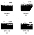
- the carbon black added to the main agent of the SIM-360 exhibits remarkable aggregation in the main agent of the SIM-360, and the main agent and the carbon black It came to separate in multiple places. Even if it separates by the revolution automatic mixer in this separated state, the separation of the above-mentioned main ingredient and carbon black is not canceled, and it was impossible to disperse carbon black to the above-mentioned main ingredient. Therefore, it was found that in order to prevent the separation of the main agent and carbon black, the carbon black concentration should be 20 wt% or less.
- the particle size of carbon black was approximately 0.5 to 2.0 ⁇ m.
- the concentration of carbon black is 1 wt%, 5 wt%, and 10 wt%, the particle size of carbon black almost entirely falls within the above range, and the variation in particle size is relatively small.
- the concentration of carbon black is 20 wt%
- the particle size of most carbon blacks falls within the range of about 0.5 to 2.0 ⁇ m as in the cases of 1 wt%, 5 wt% and 10 wt% of carbon black.
- aggregation of carbon black occurred.
- this carbon black aggregation occurred when the concentration of carbon black exceeded 10 wt%.
- the carbon black concentration is 1 wt%, 5 wt%, and 10 wt%, no aggregation occurs, and the characteristics as a silicone resin (rubber) in which carbon black is dispersed can be maintained.
- the curing time of the PDMS resin which is a silicone resin
- the particle size of carbon black even if the carbon black concentration exceeds 20 wt% It may also be possible to prevent separation of the main agent and carbon black from occurring at 2 ⁇ m or less.
- the practical carbon black concentration is 20 wt% or less.
- the interface between the transparent semicircular part 3 and the pigment semicircular part 5 is to be clearly defined to some extent when the concentration of carbon black is 10 wt% and 20 wt%. That is, it was confirmed that carbon black particles were densely packed along the interface.
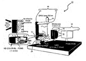
- FIG. 3 shows an angular characteristic measurement system 11 of the scattered light intensity used for this measurement.
- the disk-shaped sample 1 is placed on a rotation stage 15 having a rotation axis 13.
- the rotating shaft 13 has a branch 17 extending from the rotating shaft 13 in a direction orthogonal to the axial direction of the rotating shaft 13.
- the branch portion 17 is connected to the support 21 of the light source support portion 19.
- the light source support 19 includes a support 21 and a light source fixing unit 23 branched from the support 21.
- a DPSS laser light source 25 for emitting a laser beam with a wavelength of 532 nm is fixed to the light source fixing unit 23.
- the laser beam 27 emitted from the DPSS laser light source 25 travels downward as shown in FIG. 3 and is supported by a reflection mirror 31 supported by a reflection mirror support 29 provided on the rotation shaft 13 of the rotation stage 15. It is folded back and enters the disc-shaped sample 1.
- the reflection mirror 31 is adjusted so that the laser beam 27 is incident at an incident angle of 45 degrees with respect to the interface 7 between the transparent semicircular portion 3 and the pigment semicircular portion 5 of the disk-shaped sample 1 There is.
- the discoid sample 1 is composed of the transparent semicircular portion 3 and the pigment semicircular portion 5 as described above.
- the silicone resin which comprises both semicircle parts is resin of the same kind, the refractive index is also the same. Therefore, interface reflection at the interface 7 of the laser beam 27 incident on the discoid sample 1 does not basically occur.
- the laser beam 27 enters the pigment semicircular portion 5 without being interface-reflected at the interface 7.
- the materials of carbon black and silicone resin are different, and their refractive indices are different from each other. Therefore, the laser beam 27 reaching the carbon black is absorbed or scattered by the carbon black.
- the absorption coefficient of carbon black is 7.2 ⁇ 10 2 / cm for the laser beam 27 at a wavelength of 532 nm. Therefore, the laser beam 27 that has reached the carbon black is strongly absorbed by the carbon black. The laser beam 27 not absorbed by the carbon black is scattered by the carbon black in various directions. Of the scattered light, the light that has progressed from the pigment semicircular part 5 to the transparent semicircular part 3 is emitted from the transparent semicircular part 3 to the outside.
- a scattered light measurement unit 39 is provided having a condensing lens 35 for condensing light and a detector 37 formed of a photodiode for measuring the intensity of the laser beam 27 condensed by the condensing lens 35.
- the scattered light measurement unit 39 limits the light incident on the detector 37 by the slit 33.
- the disk-shaped sample 1, the DPSS laser light source 25 and the reflection mirror 31 are integrated by the light source support 19 and the reflection mirror support 29 connected by the rotating shaft 13 and the branch 17. It is held. Therefore, even when the rotation shaft 13 is rotated, the incident angle of the light of the DPSS laser light sources 25 and the like incident on the disk-shaped sample 1 is maintained.
- the slit 33 fixes the incident angle of the incident light as shown in FIG. Therefore, by rotating the rotation axis 13 of the rotation stage 15, only the intensity of light scattered in a specific angular direction can be measured by the scattered light measurement unit 39. That is, it becomes possible to measure the angular characteristics of the scattered light intensity emitted from the disk-shaped sample 1.
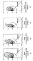
- FIG. 4 is a view showing the angular characteristic distribution of the scattered light intensity in a sample of which the carbon black concentration is (a) 1 wt%, (b) 5 wt%, (c) 10 wt%, (d) 20 wt%.
- the length of the line segment in each angular direction indicates the scattered light intensity. Therefore, the area formed by the curve connecting the tips of the line segments indicates the integrated reflection intensity (scattering intensity) of the laser beam incident on the sample.
- the concentration of carbon black is 1 wt%
- the integrated reflection intensity (scattering intensity) is large. Therefore, in order to absorb stray light in a light guide made of a transparent silicone resin, the light guide is surrounded by a silicone resin in which a pigment (carbon black) is dispersed, and stray light from the light guide is dispersed in the pigment dispersed silicone resin.
- the carbon black is absorbed at a concentration of 1 wt%, it may be considered that the influence of the scattered light from the pigment-dispersed silicone resin can not be ignored.
- the concentration of carbon black is 5 wt%, 10 wt%, and 20 wt%, the integrated reflection intensity (scattering intensity) is small. Therefore, the pigment-dispersed silicone resin for absorbing stray light is considered to be able to perform a sufficient function.
- the reason for the large integrated reflection intensity (scattering intensity) when the concentration of carbon black is 1 wt% is not necessarily clear, but is considered as follows.
- concentration of carbon black is 1 wt%
- the distance between carbon black particles is large, and the influence of multiple scattering is considered to be large. That is, when the scattered light from one carbon black collides with another carbon black and is further scattered, since the distance between each carbon black particle is large, it passes through the space between each carbon black and the transparent semicircular portion It is considered that the probability of progressing to 3 is high.
- silicone resin which is made of a transparent light guide made of a silicone resin and the same material as the transparent silicone resin and in which a pigment (carbon black) having an absorption characteristic for stray light from the light guide is dispersed.
- a pigment-dispersed silicone resin is prepared, and an optical system consisting of a two-layered silicone resin in which the light guide path is surrounded by the pigment-dispersed silicone resin is considered.
- the transparent silicone resin and the pigment-dispersed silicone resin that constitute the light guide are made of the same material, interface reflection of light at the interface between the two resins does not occur. Therefore, stray light which enters the pigment-dispersed silicone resin from the light guide is directly incident on the pigment-dispersed silicone resin, and most of the stray light is absorbed by the carbon black.
- stray light that has reached carbon black but has not been absorbed will be scattered on the carbon black surface. In some cases, part of the scattered light (reflected light) may again enter the light guide.
- an optical system made of silicone resin of the above two-layer structure for reducing the influence of stray light from the light guide has (1) the integral reflection intensity (scattering intensity) in carbon black as small as possible, and (2) carbon black as possible It is desirable for the backscattering intensity to be small.
- the scattering conditions (1) and (2) in an optical system comprising a silicone resin having a two-layer structure are also practical. It turned out that it was lost.
- the particle size of carbon black in the pigment-dispersed silicone resin it is preferable to set the particle size of carbon black in the pigment-dispersed silicone resin to 0.5 to 2.0 ⁇ m. Further, it is preferable to set the concentration of carbon black to 5 to 20 wt%.
- the order of importance is given by the interface shape between the transparent silicone resin and the pigment-dispersed silicone resin that constitute the light guide.
- FIG. 5 is a view showing that desirable scattering conditions are different due to the difference in the state on the light emission side of the light guide.
- the emission end 55 of the light guide 53 through which the light 51 as a signal passes is open without being closed by the pigment-dispersed silicone resin 57.
- the emitting end 55 is a sensor 59 that receives an optical signal (for example, an optical sensor that measures the light intensity).
- the scattered light 61 noise light
- the scattered light 61 noise light
- the scattered light 61 noise light
- the light emitting end 67 of the light guiding portion 65 through which the light 63 which is a signal passes is blocked by the pigment dispersed silicone resin 69 and the light 63 which is a signal is pigment dispersed silicone resin.
- the scattered light 71 (noise light) from the pigment-dispersed silicone resin 69 is desired to be as small as possible and not to travel backward. That is, (2) the smaller the backscattering intensity, the more important.
- the light guiding portion is not necessarily completely filled with a transparent silicone resin, and may have a space.
- the thickness of the silicone resin when the optical density (OD value) was 6 was investigated.
- the wavelength of light was 532 nm.
- the thickness of the transparent light guide and the thickness of the pigment dispersed silicone resin surrounding the upper part of the transparent light guide is about 2 mm. That is, the thickness of the microchip is at least the thickness of the transparent light guide + about 4 mm, and the thickness of the microchip is increased. Therefore, when producing a pigment dispersed silicone resin, it is not preferable to set the carbon black concentration to 1 wt% or less.
- the particle size of carbon black is 0.5 to 2.0 ⁇ m.
- (3) 10 wt% ⁇ C cb ⁇ 20 wt% ⁇ ⁇ ⁇ ⁇ Agglomeration of carbon black may occur.
- the particle size of carbon black in the region where aggregation does not occur is 0.5 to 2.0 ⁇ m.
- the concentration of carbon black is increased to some extent, depending on the concentration, the main agent SIM-360 of PDMS and carbon black come to be completely separated, making it impossible to disperse carbon black in a silicone resin.
- an optical member having a light shielding function an example of the “optical member” and the “stray light absorbing portion” in the claims of the present application
- dispersing carbon black in silicone resin for use in a microchip 5 wt% ⁇ C cb ⁇ 20 wt% is preferable, and 5 wt% ⁇ C cb ⁇ 10 wt% is more preferable.
- carbon black of a desired concentration is added to a main ingredient of silicone impression material SIM-360 before curing (an example of "uncured undispersed silicone resin” in the claims of this application) and stirred. It disperse
- three types of disk-shaped samples 1 were prepared by changing the concentration of carbon nanotubes dispersed in PDMS.
- one type of carbon black was used as a carbon-based material.
- the concentrations of carbon nanotubes dispersed in the PDMS are 0.17 wt%, 0.83 wt%, and 1.7 wt%.
- distributed to said PDMS was 10 wt%.
- the curing time of PDMS was 1 hour.
- the shape of the carbon nanotubes was almost uniform as a whole, the average diameter was 10 to 15 nm, and the average length was 10 ⁇ m.
- the angular characteristics of the scattered light intensity in a sample having a carbon nanotube concentration of 0.17 wt%, 0.83 wt%, 1.7 wt%, and a carbon black concentration of 10 wt% were measured.
- FIG. 6 is a diagram showing the angular characteristic distribution of the scattered light intensity in a sample having a carbon nanotube concentration of 0.17 wt%, 0.83 wt%, 1.7 wt% and a carbon black concentration of 10 wt%.
- the length (distance) from the origin 0 to each curve indicates the scattered light intensity. Therefore, the area of each curve represents the integrated reflection intensity (scattering intensity) of the laser beam incident on the sample.
- the integrated reflection intensity is smaller as compared to when carbon black is used as a pigment.
- the light guide is surrounded by a silicone resin in which a pigment (carbon black) is dispersed, and the light guide is formed.
- a pigment carbon black
- the integrated reflection intensity is small when the concentration of carbon black is 10 wt%, and the pigment-dispersed silicone resin for absorbing stray light can perform a sufficient function.
- the scattered light intensity is smaller than in the case of using carbon black at a concentration of 10 wt%, so when using carbon black, the silicone resin for stray light absorption in which carbon nanotubes are dispersed It is considered to be even better and capable of performing a sufficient function.
- Carbon black generally has a particle structure, but carbon nanotubes have a linear structure. Therefore, it is considered that the relative relationship between the direction (light distribution) of the carbon nanotube dispersed in the silicone resin and the traveling direction of the scattered light is a relationship suitable for the improvement of the scattering suppression effect.
- the integrated reflection intensity (scattering intensity) is 0.83 wt%. Time is the smallest. Therefore, when carbon nanotubes are used, it is considered that the optimum carbon nanotube concentration capable of minimizing the integrated reflection intensity (scattering intensity) is within the concentration range of 0.17 to 1.7 wt%. .
- the integral reflection intensity (scattering intensity) is smaller compared to when carbon black is used as a pigment, and therefore the silicone resin for absorbing stray light in which carbon nanotubes are dispersed is When using carbon black, it is considered to be better and perform a sufficient function.
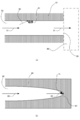
- the optical system as shown in FIG. 7 was constructed, and the stray light absorption characteristics of the silicone resin for absorbing stray light in which carbon nanotubes were dispersed and the silicone resin for absorbing stray light in which carbon black was dispersed were compared.
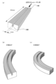
- FIG. 7 it comprises a light guide made of a transparent PDMS resin having an area of the incident surface of 2 mm ⁇ 1 mm and a length of 50 mm, and a pigment dispersed silicone resin in which a carbon based pigment surrounding this light guide is dispersed.
- a light guide made of a transparent PDMS resin having an area of the incident surface of 2 mm ⁇ 1 mm and a length of 50 mm
- a pigment dispersed silicone resin in which a carbon based pigment surrounding this light guide is dispersed.
- the transparent silicone resin and the pigment-dispersed silicone resin that constitute the light guide are made of the same material, interface reflection of light at the interface between the two resins does not occur. Therefore, stray light which enters the pigment-dispersed silicone resin from the light guide is directly incident on the pigment-dispersed silicone resin, and most of the stray light is absorbed by the carbon-based pigment.
- a laser beam with a wavelength of 532 nm having a beam diameter of 1 mm is incident from the A end of the optical member.
- part of the laser light may be a pigment-dispersed PDMS resin if the spread of the laser light and the absorption by the light guide itself are ignored. As the laser beam travels from the end A to the end B of the light guide, the laser beam is not attenuated.
- the optical member 1 has a structure in which the light guide is hollow and carbon black having a concentration of 10 wt% is dispersed in the pigment-dispersed PDMS.
- the optical member 2 has a structure in which a PDMS resin having a transparent light guide path is filled, and has a structure in which carbon black having a concentration of 10 wt% is dispersed in the pigment-dispersed PDMS.
- the optical member 3 has a structure in which a PDMS resin having a transparent light guide path is filled, and a carbon nanotube having a concentration of 0.83 wt% is dispersed in the pigment-dispersed PDMS.
- FIG. 8 shows the relationship between the bending angle of the optical member and the attenuation factor of the incident laser beam for the optical member 1, the optical member 2 and the optical member 3.
- the laser beam intensity at the B end at the bending angle of 0 degree was 100%.
- the laser beam at the B end when the bending angle is 30 degrees
- the intensity is attenuated to 10%
- the laser beam intensity at a bending angle of 30 degrees is about 6%.
- the laser beam intensity at a bending angle of 60 degrees is about 0.005%
- the attenuation factor of the optical member 2 is better than that of the optical member 1 is that, in the optical member 2, the transparent PDMS resin constituting the light guide and the carbon black pigment dispersed PDMS resin are the same material. Therefore, it is considered that interface reflection of light at the interface between both resins does not occur. That is, it is considered that the Fresnel reflection of the S polarization component as in the optical member 1 does not occur in the optical member 2.
- the laser beam intensity is already 0.005 when the bending angle is 30 degrees.
- the pigment-dispersed PDMS is carbon nanotubes at a bending angle of 30 degrees or more, a remarkable stray light quenching effect can be obtained as compared to when the pigment is carbon black. This is considered to be because, as described above, carbon nanotubes have smaller integrated reflection intensity (scattering intensity) than carbon black, so the intensity of scattered light reaching the B end of the optical member is extremely small.
- the suppression of stray light scattering when a carbon nanotube is employed as a carbon-based pigment and a resin portion in which the carbon nanotube is dispersed is used adjacent to a light guide through which incident light passes is more effective than when the pigment is carbon black. Is also more effective, and it is possible to attenuate stray light intensity better.
Landscapes
- Physics & Mathematics (AREA)
- General Physics & Mathematics (AREA)
- Optics & Photonics (AREA)
- Optical Elements Other Than Lenses (AREA)
- Optical Measuring Cells (AREA)
- Compositions Of Macromolecular Compounds (AREA)
Abstract
La présente invention a pour objet de fournir un élément optique, et similaire, qui permet la suppression de la diffusion d'une lumière parasite due à un pigment même lorsque l'élément optique, et similaire, est utilisé de manière adjacente à une partie de guidage de lumière à travers laquelle la lumière incidente est transmise. L'élément optique configuré de sorte à être utilisé de manière adjacente à la partie de guidage de lumière à travers laquelle la lumière incidente est transmise et à réduire la lumière incidente, comporte une partie de particules de carbone dispersées qui est formée à la suite de la dispersion de particules de carbone dans une région particulière dans une résine de silicone, de telle sorte que les particules de carbone soient des particules empêchant la diffusion de la lumière parasite destinées à empêcher l'intensité de la lumière d'être incidente sur les particules de carbone et d'être diffusée.
Priority Applications (1)
| Application Number | Priority Date | Filing Date | Title |
|---|---|---|---|
| US15/576,737 US10739506B2 (en) | 2015-05-27 | 2016-04-22 | Optical member, light guiding member, and method for producing optical member |
Applications Claiming Priority (4)
| Application Number | Priority Date | Filing Date | Title |
|---|---|---|---|
| JP2015-107930 | 2015-05-27 | ||
| JP2015107930A JP2016224135A (ja) | 2015-05-27 | 2015-05-27 | 光学部材、光導光部材、及び、光学部材を生産する方法 |
| JP2015-134803 | 2015-07-03 | ||
| JP2015134803A JP6682095B2 (ja) | 2015-07-03 | 2015-07-03 | 光学部材及び光導光部材 |
Publications (1)
| Publication Number | Publication Date |
|---|---|
| WO2016190016A1 true WO2016190016A1 (fr) | 2016-12-01 |
Family
ID=57393103
Family Applications (1)
| Application Number | Title | Priority Date | Filing Date |
|---|---|---|---|
| PCT/JP2016/062774 Ceased WO2016190016A1 (fr) | 2015-05-27 | 2016-04-22 | Élément optique, élément de guidage de lumière et procédé permettant de produire un élément optique |
Country Status (2)
| Country | Link |
|---|---|
| US (1) | US10739506B2 (fr) |
| WO (1) | WO2016190016A1 (fr) |
Families Citing this family (1)
| Publication number | Priority date | Publication date | Assignee | Title |
|---|---|---|---|---|
| EP4384856A4 (fr) * | 2021-08-10 | 2025-10-22 | Edmund Optics Inc | Composant optique pour réorienter la lumière |
Citations (7)
| Publication number | Priority date | Publication date | Assignee | Title |
|---|---|---|---|---|
| JP2006337837A (ja) * | 2005-06-03 | 2006-12-14 | Shin Etsu Polymer Co Ltd | 光射出方向制御フィルム |
| JP2008102278A (ja) * | 2006-10-18 | 2008-05-01 | Shin Etsu Polymer Co Ltd | 電卓用視野角制御フィルム及び電卓 |
| JP2011186437A (ja) * | 2010-02-12 | 2011-09-22 | Canon Inc | 光学素子用の遮光膜および光学素子 |
| JP2013020118A (ja) * | 2011-07-12 | 2013-01-31 | Shin Etsu Polymer Co Ltd | 機能性遮光フィルム |
| JP2013205509A (ja) * | 2012-03-27 | 2013-10-07 | Dainippon Printing Co Ltd | 光学シート、これを備えた表示装置、および光学シートの製造方法 |
| JP2014021231A (ja) * | 2012-07-17 | 2014-02-03 | Canon Chemicals Inc | 光学素子用内面反射防止黒色塗料 |
| JP2014071229A (ja) * | 2012-09-28 | 2014-04-21 | Toshiba Tec Corp | 遮光性インク、マイクロレンズアレイユニット及び画像形成装置 |
Family Cites Families (3)
| Publication number | Priority date | Publication date | Assignee | Title |
|---|---|---|---|---|
| EP2208096B1 (fr) * | 2007-10-16 | 2019-11-27 | 3M Innovative Properties Company | Film anti-reflet à transmission plus élevée |
| JP5665811B2 (ja) | 2012-08-02 | 2015-02-04 | 国立大学法人九州大学 | 光誘起蛍光測定器 |
| US9094593B2 (en) * | 2013-07-30 | 2015-07-28 | Heptagon Micro Optics Pte. Ltd. | Optoelectronic modules that have shielding to reduce light leakage or stray light, and fabrication methods for such modules |
-
2016
- 2016-04-22 WO PCT/JP2016/062774 patent/WO2016190016A1/fr not_active Ceased
- 2016-04-22 US US15/576,737 patent/US10739506B2/en active Active
Patent Citations (7)
| Publication number | Priority date | Publication date | Assignee | Title |
|---|---|---|---|---|
| JP2006337837A (ja) * | 2005-06-03 | 2006-12-14 | Shin Etsu Polymer Co Ltd | 光射出方向制御フィルム |
| JP2008102278A (ja) * | 2006-10-18 | 2008-05-01 | Shin Etsu Polymer Co Ltd | 電卓用視野角制御フィルム及び電卓 |
| JP2011186437A (ja) * | 2010-02-12 | 2011-09-22 | Canon Inc | 光学素子用の遮光膜および光学素子 |
| JP2013020118A (ja) * | 2011-07-12 | 2013-01-31 | Shin Etsu Polymer Co Ltd | 機能性遮光フィルム |
| JP2013205509A (ja) * | 2012-03-27 | 2013-10-07 | Dainippon Printing Co Ltd | 光学シート、これを備えた表示装置、および光学シートの製造方法 |
| JP2014021231A (ja) * | 2012-07-17 | 2014-02-03 | Canon Chemicals Inc | 光学素子用内面反射防止黒色塗料 |
| JP2014071229A (ja) * | 2012-09-28 | 2014-04-21 | Toshiba Tec Corp | 遮光性インク、マイクロレンズアレイユニット及び画像形成装置 |
Also Published As
| Publication number | Publication date |
|---|---|
| US20190011624A1 (en) | 2019-01-10 |
| US10739506B2 (en) | 2020-08-11 |
Similar Documents
| Publication | Publication Date | Title |
|---|---|---|
| Nashold et al. | Investigations of optical limiting mechanisms in carbon particle suspensions and fullerene solutions | |
| JP5325679B2 (ja) | 低コヒーレンス光源を用いた動的光散乱測定装置及び光散乱強度測定方法 | |
| DE102013211854B4 (de) | Verfahren und Vorrichtung zur Bestimmung einer spektralen Änderung von gestreutem Licht | |
| JP6682095B2 (ja) | 光学部材及び光導光部材 | |
| EP2095071A1 (fr) | Detecteur d'inclinaison a niveau optoelectronique | |
| WO2010057490A1 (fr) | Ensemble de cellules pour des détecteurs de diffusion de la lumière à propriétés autofocus | |
| JP6399520B2 (ja) | 光測定装置及び光測定方法 | |
| EP2600139A1 (fr) | Élément de calibrage et procédé de calibrage d'un scatteromètre | |
| JP6931895B2 (ja) | 光学部材、光導光部材、及び、光学部材を生産する方法 | |
| RU2610942C1 (ru) | Способ оптического измерения счетной концентрации дисперсных частиц в жидких средах и устройство для его осуществления | |
| WO2016190016A1 (fr) | Élément optique, élément de guidage de lumière et procédé permettant de produire un élément optique | |
| JP2016224135A (ja) | 光学部材、光導光部材、及び、光学部材を生産する方法 | |
| WO2019009209A1 (fr) | Dispositif de mesure optique, élément de guidage de lumière et procédé de mesure optique | |
| AT513186B1 (de) | Kalibrierelement und Verfahren zur Herstellung eines solchen Kalibrierelements | |
| JP2015031682A (ja) | 蛍光検出器 | |
| CN102954957B (zh) | 一种拉曼光谱仪探针及其制作方法 | |
| CN104614363A (zh) | 一种基于液芯波导的拉曼光谱测试系统 | |
| JP2020085615A (ja) | 光学測定器 | |
| JPS5910837A (ja) | 物理的量値並びに物質濃度の光学的測定装置 | |
| Yang et al. | A sandwich SERS detection system based on optical convergence and synergistic enhancement effects | |
| JP6924439B2 (ja) | 光測定装置、導光部材及び光測定方法 | |
| JP6664771B2 (ja) | 光学系構造体、光学測定装置及び光学測定方法 | |
| JP2008249363A (ja) | 濁度計 | |
| David et al. | Fundamental review to ozone gas sensing using optical fibre sensors | |
| JP6723534B2 (ja) | 光学部材、光測定装置、試料保持部材、光測定システム及び特定波長集光部材 |
Legal Events
| Date | Code | Title | Description |
|---|---|---|---|
| 121 | Ep: the epo has been informed by wipo that ep was designated in this application |
Ref document number: 16799724 Country of ref document: EP Kind code of ref document: A1 |
|
| NENP | Non-entry into the national phase |
Ref country code: DE |
|
| 122 | Ep: pct application non-entry in european phase |
Ref document number: 16799724 Country of ref document: EP Kind code of ref document: A1 |