WO2016194112A1 - Système optique simple foyer et dispositif optique équipé de ce dernier - Google Patents
Système optique simple foyer et dispositif optique équipé de ce dernier Download PDFInfo
- Publication number
- WO2016194112A1 WO2016194112A1 PCT/JP2015/065800 JP2015065800W WO2016194112A1 WO 2016194112 A1 WO2016194112 A1 WO 2016194112A1 JP 2015065800 W JP2015065800 W JP 2015065800W WO 2016194112 A1 WO2016194112 A1 WO 2016194112A1
- Authority
- WO
- WIPO (PCT)
- Prior art keywords
- lens
- optical system
- subgroup
- group
- focus optical
- Prior art date
- Legal status (The legal status is an assumption and is not a legal conclusion. Google has not performed a legal analysis and makes no representation as to the accuracy of the status listed.)
- Ceased
Links
Images





Classifications
-
- G—PHYSICS
- G02—OPTICS
- G02B—OPTICAL ELEMENTS, SYSTEMS OR APPARATUS
- G02B9/00—Optical objectives characterised both by the number of the components and their arrangements according to their sign, i.e. + or -
- G02B9/64—Optical objectives characterised both by the number of the components and their arrangements according to their sign, i.e. + or - having more than six components
-
- G—PHYSICS
- G02—OPTICS
- G02B—OPTICAL ELEMENTS, SYSTEMS OR APPARATUS
- G02B13/00—Optical objectives specially designed for the purposes specified below
- G02B13/001—Miniaturised objectives for electronic devices, e.g. portable telephones, webcams, PDAs, small digital cameras
- G02B13/0055—Miniaturised objectives for electronic devices, e.g. portable telephones, webcams, PDAs, small digital cameras employing a special optical element
- G02B13/006—Miniaturised objectives for electronic devices, e.g. portable telephones, webcams, PDAs, small digital cameras employing a special optical element at least one element being a compound optical element, e.g. cemented elements
-
- G—PHYSICS
- G02—OPTICS
- G02B—OPTICAL ELEMENTS, SYSTEMS OR APPARATUS
- G02B13/00—Optical objectives specially designed for the purposes specified below
- G02B13/001—Miniaturised objectives for electronic devices, e.g. portable telephones, webcams, PDAs, small digital cameras
- G02B13/0015—Miniaturised objectives for electronic devices, e.g. portable telephones, webcams, PDAs, small digital cameras characterised by the lens design
- G02B13/002—Miniaturised objectives for electronic devices, e.g. portable telephones, webcams, PDAs, small digital cameras characterised by the lens design having at least one aspherical surface
- G02B13/0045—Miniaturised objectives for electronic devices, e.g. portable telephones, webcams, PDAs, small digital cameras characterised by the lens design having at least one aspherical surface having five or more lenses
-
- G—PHYSICS
- G02—OPTICS
- G02B—OPTICAL ELEMENTS, SYSTEMS OR APPARATUS
- G02B13/00—Optical objectives specially designed for the purposes specified below
- G02B13/04—Reversed telephoto objectives
-
- G—PHYSICS
- G02—OPTICS
- G02B—OPTICAL ELEMENTS, SYSTEMS OR APPARATUS
- G02B13/00—Optical objectives specially designed for the purposes specified below
- G02B13/16—Optical objectives specially designed for the purposes specified below for use in conjunction with image converters or intensifiers, or for use with projectors, e.g. objectives for projection TV
-
- G—PHYSICS
- G02—OPTICS
- G02B—OPTICAL ELEMENTS, SYSTEMS OR APPARATUS
- G02B7/00—Mountings, adjusting means, or light-tight connections, for optical elements
- G02B7/02—Mountings, adjusting means, or light-tight connections, for optical elements for lenses
- G02B7/04—Mountings, adjusting means, or light-tight connections, for optical elements for lenses with mechanism for focusing or varying magnification
-
- H—ELECTRICITY
- H04—ELECTRIC COMMUNICATION TECHNIQUE
- H04N—PICTORIAL COMMUNICATION, e.g. TELEVISION
- H04N23/00—Cameras or camera modules comprising electronic image sensors; Control thereof
- H04N23/50—Constructional details
- H04N23/54—Mounting of pick-up tubes, electronic image sensors, deviation or focusing coils
-
- G—PHYSICS
- G02—OPTICS
- G02B—OPTICAL ELEMENTS, SYSTEMS OR APPARATUS
- G02B21/00—Microscopes
- G02B21/36—Microscopes arranged for photographic purposes or projection purposes or digital imaging or video purposes including associated control and data processing arrangements
-
- G—PHYSICS
- G02—OPTICS
- G02B—OPTICAL ELEMENTS, SYSTEMS OR APPARATUS
- G02B5/00—Optical elements other than lenses
- G02B5/005—Diaphragms
-
- G—PHYSICS
- G02—OPTICS
- G02B—OPTICAL ELEMENTS, SYSTEMS OR APPARATUS
- G02B7/00—Mountings, adjusting means, or light-tight connections, for optical elements
- G02B7/02—Mountings, adjusting means, or light-tight connections, for optical elements for lenses
- G02B7/021—Mountings, adjusting means, or light-tight connections, for optical elements for lenses for more than one lens
-
- G—PHYSICS
- G03—PHOTOGRAPHY; CINEMATOGRAPHY; ANALOGOUS TECHNIQUES USING WAVES OTHER THAN OPTICAL WAVES; ELECTROGRAPHY; HOLOGRAPHY
- G03B—APPARATUS OR ARRANGEMENTS FOR TAKING PHOTOGRAPHS OR FOR PROJECTING OR VIEWING THEM; APPARATUS OR ARRANGEMENTS EMPLOYING ANALOGOUS TECHNIQUES USING WAVES OTHER THAN OPTICAL WAVES; ACCESSORIES THEREFOR
- G03B21/00—Projectors or projection-type viewers; Accessories therefor
- G03B21/14—Details
- G03B21/147—Optical correction of image distortions, e.g. keystone
-
- H—ELECTRICITY
- H04—ELECTRIC COMMUNICATION TECHNIQUE
- H04N—PICTORIAL COMMUNICATION, e.g. TELEVISION
- H04N23/00—Cameras or camera modules comprising electronic image sensors; Control thereof
- H04N23/50—Constructional details
- H04N23/55—Optical parts specially adapted for electronic image sensors; Mounting thereof
-
- H—ELECTRICITY
- H04—ELECTRIC COMMUNICATION TECHNIQUE
- H04N—PICTORIAL COMMUNICATION, e.g. TELEVISION
- H04N23/00—Cameras or camera modules comprising electronic image sensors; Control thereof
- H04N23/60—Control of cameras or camera modules
- H04N23/63—Control of cameras or camera modules by using electronic viewfinders
- H04N23/631—Graphical user interfaces [GUI] specially adapted for controlling image capture or setting capture parameters
Definitions
- the present invention relates to a single focus optical system and an optical apparatus including the same.
- An example of focus in an imaging optical system with a large aperture ratio is focus on a telephoto lens.
- a conventional telephoto lens a telephoto lens constituted by a first lens group having a positive refractive power, a second lens group having a negative refractive power, and a third lens group having a positive refractive power in order from the object.
- the second lens group moves.
- the aberration variation can be reduced over a considerable distance from infinity.
- the angle of view of the conventional telephoto lens is less than 15 degrees, it is only possible to maintain good imaging performance from the center of the shooting range to the periphery.
- the Gauss type optical system includes, in order from the object side, an object side group having a positive refractive power and an image side group having a positive refractive power.
- the object side group is composed of two to three positive lenses and one negative lens. This negative lens may be cemented with the immediately preceding positive lens.
- the image side group includes one negative lens and two to three positive lenses. This negative lens may also be cemented with the positive lens immediately after.
- the shape on the object side and the shape on the image side are generally symmetrical and concentric with respect to the center.
- the center of curvature of the two lens surfaces is located near the center of each lens.
- each aberration can be corrected to some extent even with a large aperture ratio.
- a limit of an angle of view of less than 50 degrees is the limit in a Gauss type optical system. Therefore, it is difficult to realize an angle of view of 50 degrees or more with a Gauss type optical system.
- Patent Document 3 Patent Document 4, Patent Document 5, and Patent Document 6, the F number is 1.4, but the F number is further decreased or the field angle is increased. This makes it more difficult to correct the various aberrations described above.
- the present invention has been made in view of such a problem, and has a wide angle of view and a small F number, and a single focus optical system in which various aberrations are well corrected, and an optical apparatus including the same.
- the purpose is to provide.
- the single-focus optical system of the present invention includes: A single-focus optical system that forms a conjugate relationship between a conjugate point on the enlargement side with a longer distance and a conjugate point on the reduction side with a shorter distance, Single-focus optical systems, in order from the magnification side, A first lens group having a positive refractive power; A second lens group having negative refractive power; A third lens group having a positive refractive power,
- the lens component is a single lens or a cemented lens,
- the first lens group includes, in order from the magnification side, the first sub group, the second sub group, and the third sub group, or the first sub group, one positive lens component, the second sub group, and the third sub group.
- the first sub group consists of one negative lens component or a plurality of consecutive negative lens components
- the second subgroup consists of two meniscus lens components with their concave surfaces facing each other
- the third subgroup includes a plurality of positive lens components and includes all positive lens components adjacent to the reduction side of the second subgroup in the first lens group
- the third lens group in order from the magnification side, consists of a front side subgroup and a rear side subgroup
- the front subgroup consists only of positive lens components
- the optical device of the present invention is An optical system, and an imaging device disposed on the reduction side,
- the imaging element has an imaging surface, and converts an image formed on the imaging surface by an optical system into an electrical signal,
- the optical system is the above-described single focus optical system.
- Another optical device of the present invention is An optical system, and a display element disposed on the reduction side, The display element has a display surface, The image displayed on the display surface is projected to the enlargement side by the optical system,
- the optical system is the above-described single focus optical system.
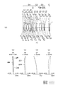
- FIG. 2 is a cross-sectional view and aberration diagrams of a single focus optical system according to Example 1, wherein (a) is a lens cross-sectional view when focusing on an object at infinity, and (b), (c), (d) and (e). These are aberration diagrams when focusing on an object at infinity.
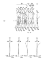
- FIG. 6 is a cross-sectional view and aberration diagrams of a single focus optical system according to Example 2, wherein (a) is a lens cross-sectional view when focusing on an object at infinity, (b), (c), (d), and (e). These are aberration diagrams when focusing on an object at infinity.
- FIG. 6A is a cross-sectional view and aberration diagrams of a single focus optical system according to Example 3, wherein FIG. 5A is a lens cross-sectional view at the time of focusing on an object at infinity, and FIG. These are aberration diagrams when focusing on an object at infinity.
- FIG. 6A is a cross-sectional view and aberration diagrams of a single focus optical system according to Example 4, wherein FIG. 5A is a lens cross-sectional view when focusing on an object at infinity, and FIG. These are aberration diagrams when focusing on an object at infinity.
- FIG. 7A is a cross-sectional view and aberration diagrams of a single focus optical system according to Example 5, wherein FIG.
- FIG. 5A is a lens cross-sectional view when focusing on an object at infinity
- FIG. 5B, FIG. These are aberration diagrams when focusing on an object at infinity
- FIG. 6A is a cross-sectional view and aberration diagrams of a single focus optical system according to Example 6, wherein FIG. 5A is a lens cross-sectional view at the time of focusing on an object at infinity, and FIG. These are aberration diagrams when focusing on an object at infinity.
- FIG. 7A is a cross-sectional view and aberration diagrams of a single focus optical system according to Example 7, wherein FIG. 5A is a lens cross-sectional view when focusing on an object at infinity, and FIG. These are aberration diagrams when focusing on an object at infinity.
- FIG. 9A is a cross-sectional view and aberration diagrams of a single focus optical system according to Example 8, wherein (a) is a lens cross-sectional view when focusing on an object at infinity, (b), (c), (d) and (e). These are aberration diagrams when focusing on an object at infinity.
- FIG. 9A is a cross-sectional view and an aberration diagram of a single focus optical system according to Example 9, wherein (a) is a lens cross-sectional view at the time of focusing on an object at infinity, These are aberration diagrams when focusing on an object at infinity.
- FIG. 9A is a cross-sectional view and aberration diagrams of a single focus optical system according to Example 10, wherein FIG.
- FIG. 10A is a lens cross-sectional view when focusing on an object at infinity, and FIG. These are aberration diagrams when focusing on an object at infinity.
- FIG. 10A is a cross-sectional view and aberration diagrams of a single focus optical system according to Example 11, wherein FIG. 10A is a lens cross-sectional view when focusing on an object at infinity, and FIG. These are aberration diagrams when focusing on an object at infinity.
- FIG. 14A is a cross-sectional view and aberration diagrams of a single focus optical system according to Example 12, wherein FIG. 10A is a lens cross-sectional view when focusing on an object at infinity, and FIG. These are aberration diagrams when focusing on an object at infinity.
- the single-focus optical system of the present embodiment is a single-focus optical system that forms a conjugate relationship between a conjugate point on the enlargement side with a longer distance and a conjugate point on the reduction side with a shorter distance.
- the first lens group includes a first sub group, a second sub group, and a third sub group in order from the enlargement side, or the first sub group and one positive lens component.
- the second subgroup and the third subgroup, and the first subgroup is composed of one negative lens component or a plurality of consecutive negative lens components, and the second subgroup includes concave surfaces. It consists of two meniscus lens components facing each other, the third subgroup consists of a plurality of positive lens components, and The lens group includes all positive lens components adjacent to the reduction side of the second sub group, and the third lens group includes a front sub group and a rear sub group in order from the enlargement side.
- the group is composed only of positive lens components, and at the time of focusing, the first lens group is fixed, the second lens group is movable, and the rear sub group is fixed, and the first lens group and the second lens group
- the single focus optical system of the present embodiment will be described while comparing the single focus optical system of the present embodiment and a Gauss type optical system.
- the object side corresponds to the enlargement side
- the image side corresponds to the reduction side.
- the single focus optical system of the present embodiment is an optical system having a large aperture ratio. Therefore, similarly to the focus in the conventional telephoto lens, the optical system includes a first lens group having a positive refractive power, a second lens group having a negative refractive power, and a third lens group having a positive refractive power. And the second lens group is moved during focusing.
- the focus method adopts the focus method of the conventional telephoto lens, but the lens configuration of the optical system adopts a lens configuration different from the conventional telephoto lens. Yes.
- the total aberration amount is the sum of the aberration amount generated in the first lens group having positive refractive power and the aberration amount generated in the third lens group having positive refractive power. In particular, it is important to reduce the amount of aberration generated in the first lens group.
- the Gauss type optical system has high imaging performance. Therefore, by modifying the Gauss type optical system, it is possible to further increase the aperture ratio and further widen the angle of view. Therefore, in the single focus optical system of the present embodiment, the Gauss type optical system can be adapted to a wider field angle in order to keep the aberration fluctuation at the time of focusing as small as possible even in a wide field angle, for example, a field angle of 50 degrees or more.
- the deformed optical system is used as a first lens group having positive refractive power.
- the single focus optical system of the present embodiment is based on a Gauss type optical system. That is, various ideas are added while maintaining the basic lens arrangement and lens shape (hereinafter referred to as “basic arrangement”) as much as possible in the Gaussian type. Therefore, the first lens group has the same basic arrangement as the Gaussian object side group and image side group.
- the first lens group is different from the Gauss type refractive power arrangement by maintaining the basic arrangement in the Gauss type object side group and the basic arrangement in the image side group as much as possible while shifting the balance of the refractive power arrangement.
- the refractive power is arranged.
- the portion corresponding to the object side group in the first lens group is in a state where the positive refractive power in the object side group is shifted to the negative side. Further, in the first lens group, the portion corresponding to the image side group is in a state where the positive refractive power in the image side group is largely shifted to the positive side.
- the shift of the refractive power to the negative side is to change the positive refractive power to a small negative refractive power or to change the positive refractive power to a smaller positive refractive power.
- the shift of the refractive power to the positive side is to change the positive refractive power to a larger positive refractive power.
- the configuration of the optical system is reconfigured so as to be advantageous for aberration correction while maintaining the basic arrangement of the Gauss type as much as possible. That is, in the Gauss type, the refractive power of the portion corresponding to the Gauss type object side group is shifted to the negative side, and the refractive power of the portion corresponding to the image side group is greatly shifted to the positive side.
- the basic array is reconstructed.
- the first lens group includes three subgroups. As long as the focal length of the entire single focus optical system is long, it is better not to shift the refractive power of the portion corresponding to the object side group to the negative side so much. In view of such circumstances, in this case, one positive lens component is disposed immediately before the second subgroup, that is, between the first subgroup and the second subgroup including one or more negative lens components. May be. By doing so, spherical aberration and longitudinal chromatic aberration can be corrected satisfactorily. However, it is not preferable to arrange two or more positive lens components because the entire length of the optical system is increased and the diameter of the portion corresponding to the object side group is enlarged.
- the positive lens component may not be disposed between the first sub group and the second sub group. By doing so, the angle of view can be widened.
- the second subgroup consists of two meniscus lens components with concave surfaces facing each other.
- One meniscus lens component is disposed with the concave surface facing the reduction side
- the other meniscus lens component is disposed with the concave surface facing the enlargement side. Therefore, in the single focus optical system according to the present embodiment, since the portion on the enlargement side from one meniscus lens component becomes a portion corresponding to the object side group, the refractive power of this portion is shifted to the negative side. Further, since the reduction side portion of the other meniscus lens component corresponds to the image side group, the refractive power of this portion is greatly shifted to the positive side.
- the second lens group is movable for focusing.
- the third lens group is basically fixed. However, aberration variation occurs when the second lens group moves during focusing. Therefore, the number of moving lens groups may be increased in accordance with the amount of aberration variation.
- the third lens group is composed of a front subgroup and a rear subgroup in order from the magnification side. Further, the front side subgroup consists of only a positive lens component. Therefore, if the fluctuation amount of the aberration fluctuation at the time of focusing is unacceptably large, the front side sub group together with the second lens group at the time of focusing may be moved while changing the distance between them.
- the first lens group and the rear subgroup are fixed. Further, the distance between the first lens group and the second lens group, the distance between the second lens group and the front side sub group, and the distance between the front side sub group and the rear side sub group are all variable. In addition, the intervals between the lens surfaces in the first lens group, the second lens group, the front side sub group, and the rear side sub group are constant.
- the refractive power in the portion corresponding to the object side group is shifted to the negative side and the refraction in the portion corresponding to the image side group is compared with the Gauss type optical system.
- the single focus optical system of the present embodiment is different from a Gauss type optical system.
- the single focus optical system of the present embodiment also has a Gauss type basic arrangement. Therefore, it can be said that the single focus optical system of the present embodiment is based on an optical system having a very high aberration correction potential. Therefore, in the single focus optical system of the present embodiment, particularly, spherical aberration, coma aberration, axial chromatic aberration, and lateral chromatic aberration can be corrected extremely well. As a result, it is possible to realize a single focus optical system having higher imaging performance than a conventional Gauss type optical system. For example, in a single focus optical system, an F number smaller than 1.4 and an angle of view of 50 ° or more can be secured.
- the single focus optical system of the present embodiment in the category of the standard lens to the wide angle lens, the single focus optical system having an F number smaller than 1.4 and extremely high aberration correction potential. Can be provided. In particular, in terms of imaging performance, it can have imaging performance at a level that surpasses the conventional single focus optical system for 35 mm film size.
- the second lens group is composed of one lens component.
- the best way to suppress aberration fluctuations with focus is to move the second lens group on the optical axis. At that time, the weight of the moving lens group becomes a problem. Therefore, by configuring the second lens group with one lens component, it becomes possible to focus at high speed without deteriorating aberration fluctuations.
- one lens component of the second lens group is a negative lens component
- the reduction side surface of the negative lens component of the second lens group is a concave surface
- the second lens group The curvature of the reduction side surface in the negative lens component is preferably larger than the curvature of the enlargement side surface.
- the rear subgroup includes a positive lens and a negative lens.
- the rear side subgroup of the third lens group includes a positive lens, which is advantageous for securing telecentricity on the reduction side. Further, since the rear subgroup of the third lens group includes a negative lens, while ensuring telecentricity, spherical aberration, coma, astigmatism, field curvature, axial chromatic aberration, The lateral chromatic aberration can be corrected better.
- the rear side subgroup includes a positive lens, a negative lens, and a positive lens in order from the magnification side.
- the rear side subgroup includes a cemented lens of a positive lens and a negative lens.
- the rear side subgroup includes one positive lens and one negative lens
- the second subgroup is changed while changing the interval between the second lens group and the front side subgroup during focusing. It is preferable to move the lens group and the front side sub group.
- Each aberration is changed by moving the second lens group during focusing.
- the variation amount of each aberration is unacceptably large, it is preferable to move only the front side subgroup of the third lens group along the optical axis while changing the distance between them together with the second lens group.
- variation of astigmatism can be suppressed.
- the front subgroup is preferably a positive single lens.
- the first lens group has a reduction-side positive lens component on the most reduction side.
- the second sub group includes a cemented lens with a concave surface facing the enlargement side, and one of the two meniscus lens components is a cemented lens of the second sub group.
- the cemented lens of the second subgroup is preferably composed of a negative lens and a positive lens in order from the magnification side.
- the second sub group includes a cemented lens having a concave surface facing the enlargement side, and a reduction side lens component, and one of the two meniscus lens components is
- the second sub-group cemented lens, the other is a reduction-side lens component, and the second sub-group cemented lens is composed of a negative lens and a positive lens in order from the magnification side, and the reduction-side lens component is
- the reduction side lens component is disposed on the enlargement side of the second sub group cemented lens adjacent to the second sub group cemented lens, and has a meniscus shape with a convex surface facing the enlargement side.
- spherical aberration, coma, astigmatism, curvature of field, axial chromatic aberration, and lateral chromatic aberration are improved even when the aperture ratio is increased or the angle of view is increased. Can be corrected.
- the third sub group is disposed on the reduction side of the second sub group.
- Astigmatism is particularly easily corrected by making sure that the upper limit of conditional expression (1) is not exceeded. By making sure that the lower limit value of conditional expression (1) is not exceeded, it is particularly easy to correct barrel distortion.
- conditional expression (1 ′) instead of conditional expression (1). 0.85 ⁇ SF 11 ⁇ 3.0 (1 ′)
- conditional expression (1 ′′) is satisfied instead of conditional expression (1). 0.95 ⁇ SF 11 ⁇ 2.7 (1 ")
- conditional expression (2) 1.6 ⁇ SF 12 ⁇ 10 (2 ′)
- conditional expression (2 ′′) is satisfied instead of conditional expression (2).
- the second sub group includes a cemented lens
- conditional expression (3) ⁇ 12 ⁇ SF 13 ⁇ 2.5 (3 ′)
- conditional expression (3 ′′) is satisfied instead of conditional expression (3).
- the plurality of positive lens components in the third sub group includes a front positive lens component located closest to the enlargement side and a rear positive lens component located closest to the reduction side. It is preferable that the following conditional expression (4) is satisfied.
- SF 14 (R F14 + R R14 ) / (R F14 -R R14 )
- SF 15 (R F15 + R R15 ) / (R F15 -R R15 )
- R F14 is the radius of curvature of the enlarged side surface of the front positive lens component
- R R14 is the radius of curvature of the reduction side surface of the front positive lens component
- R F15 is the radius of curvature of the enlarged side surface of the rear positive lens component
- R R15 is the radius of curvature of the reduction side surface in the rear positive lens component
- the axial ray height is high at a position where a plurality of positive lens components are arranged. For this reason, the shape of each lens component in the plurality of positive lens components is closely related to correction of spherical aberration that affects the sharpness of the entire image.
- this axial ray bundle is in a divergent state on the enlarged side of the third subgroup.
- the third subgroup in order to shift the divergent state to the convergent state, it is preferable to arrange each of the positive lens components so that the shaping factor of each positive lens component becomes a negative direction from the enlargement side to the reduction side. . And it is necessary to take an appropriate value with a difference in shaping factor between the positive lens components located at both ends of the plurality of positive lens components.
- conditional expression (4 ′) instead of conditional expression (4). 0.30 ⁇ SF 14 -SF 15 ⁇ 6.0 (4 ′)
- conditional expression (4 ′′) is satisfied instead of conditional expression (4). 0.45 ⁇ SF 14 -SF 15 ⁇ 5.5 (4 ")
- conditional expression (5) 0.85 ⁇ SF 21 ⁇ 3.0 (5 ′)
- conditional expression (5 ′′) 0.90 ⁇ SF 21 ⁇ 2.5 (5 ")
- conditional expression (6 ′) instead of conditional expression (6).
- conditional expression (6 ′) ⁇ 0.2 ⁇ SF 31 ⁇ 1.3 (6 ′)
- conditional expression (6 ′′) is satisfied instead of conditional expression (6).
- the first lens group has a reduction-side positive lens component on the most reduction side
- the reduction-side positive lens component is a single lens
- the horizontal axis is Nd 1PR
- the vertical axis is Nd 1PR
- Nd 1PR ⁇ ⁇ ⁇ d 1PR + ⁇ 1PR
- the range of the following conditional expression (11) Nd 1PR and ⁇ d of the reduction-side positive lens component in both the area determined by the straight line when ⁇ 1PR 2.25 and the area determined by the following conditional expressions (12) and (13)
- 1PR is included.
- Nd 1PR is the refractive index of the reduction-side positive lens component
- ⁇ d 1PR is the Abbe number of the positive lens component on the reduction side, It is.
- the axial ray height is high at a position where a plurality of positive lens components are arranged. For this reason, axial chromatic aberration and chromatic aberration such as spherical aberration are particularly likely to occur in a plurality of positive lens components.
- the reduction-side positive lens component is located closest to the reduction side in the first lens group. This position is the position farthest from the cemented lens of the first lens group.
- the reduction-side positive lens component In order to reduce the size and weight of the first lens group, it is preferable to configure the reduction-side positive lens component with a single lens.
- chromatic aberration is likely to occur at the position where the reduction-side positive lens component is disposed. Therefore, when the reduction-side positive lens component is composed of a single lens, the refractive index and Abbe number of the reduction-side positive lens component are included in the region determined by the conditional expressions (11), (12), and (13). To do. By doing so, it is possible to suppress the occurrence of longitudinal chromatic aberration and spherical aberration.
- the second lens group is composed of one negative lens component
- the negative lens component of the second lens group is a single lens
- the horizontal axis is Nd 2NF
- the vertical axis is ⁇ d.
- Nd 2NF ⁇ ⁇ ⁇ d 2NF + ⁇ 2NF
- Preferably 2NF is included.
- Nd 2NF is the refractive index of the negative lens component of the second lens group
- ⁇ d 2NF is the Abbe number of the negative lens component of the second lens group
- the refractive index and Abbe number of the negative lens component of the second lens group are included in the region determined by conditional expressions (14), (15), and (16). By doing so, it is possible to suppress the occurrence of axial chromatic aberration, lateral chromatic aberration, chromatic aberration of spherical aberration, or color coma.
- the first lens group has a magnifying side lens component on the most magnifying side and satisfies the following conditional expression (A). 0 ⁇ f / e N1F ⁇ 2 (A) here, f is the focal length of the entire single-focus optical system when focusing on an object at infinity, e N1F is the maximum effective aperture of the magnification side lens component of the first lens group, It is.
- conditional expression (A) If the upper limit of conditional expression (A) is exceeded, it becomes difficult to widen the angle of view. That is, if the field angle is increased, spherical aberration, distortion, and astigmatism are likely to occur. On the other hand, if the lower limit of conditional expression (A) is not reached, the optical system tends to be enlarged in the radial direction.
- conditional expression (A ′) instead of the conditional expression (A).
- conditional expression (A ′′) is satisfied instead of conditional expression (A).
- the single focus optical system of the present embodiment it is preferable to have an aperture stop and satisfy the following conditional expression (B). 0 ⁇ (f / e AS ) / Fno ⁇ 2 (B) here, f is the focal length of the entire single-focus optical system when focusing on an object at infinity, e AS is the maximum diameter of the aperture stop, Fno is the F number of the entire single-focus optical system when focusing on an object at infinity, It is.
- conditional expression (B) If the upper limit of conditional expression (B) is exceeded, it will be difficult to widen the angle of view. That is, if the angle of view is increased, it is difficult to correct spherical aberration and chromatic aberration. On the other hand, if the lower limit of conditional expression (B) is not reached, the optical system tends to be enlarged in the radial direction.
- conditional expression (B ′) it is preferable to satisfy the following conditional expression (B ′) instead of the conditional expression (B). 0.2 ⁇ (f / e AS ) / Fno ⁇ 1 (B ′) Further, it is more preferable that the following conditional expression (B ′′) is satisfied instead of conditional expression (B). 0.3 ⁇ (f / e AS ) / Fno ⁇ 0.9 (B ′′)
- the single focus optical system of this embodiment satisfies the following conditional expression (C). 0 ⁇ T air_max / ⁇ d ⁇ 0.27 (C) here, T air — max is the largest on-axis air interval between the surface located on the most enlargement side and the surface located on the most reduction side of the single focus optical system, ⁇ d is the axial distance from the surface located closest to the magnification side to the surface located closest to the reduction side of the single focus optical system, It is.
- Conditional expression (C) is a conditional expression that is advantageous for securing high optical performance, shortening the overall length of the optical system, and reducing the outer diameter of the imaging optical system.
- ⁇ d that is, the axial distance from the lens surface located closest to the enlargement side to the lens surface located closest to the reduction side of the single focus optical system
- the air performance between the lenses is excessively widened to improve the optical performance. Securing easily leads to an increase in the total length of the optical system and an increase in the diameter of the optical system.
- conditional expression (C) is advantageous in securing the number of lenses necessary for realizing high optical performance while shortening the overall length and reducing the diameter of the optical system.
- conditional expression (C ′) it is preferable to satisfy the following conditional expression (C ′) instead of the conditional expression (C). 0.03 ⁇ T air_max / ⁇ d ⁇ 0.2 ( C ′) Further, it is more preferable that the following conditional expression (C ′′) is satisfied instead of conditional expression (C). 0.07 ⁇ T air_max / ⁇ d ⁇ 0.18 ( C ′′)
- the optical device includes an optical system and an image sensor disposed on the reduction side,
- the image pickup device has an image pickup surface, converts an image formed on the image pickup surface by the optical system into an electric signal, and the optical system is the above-described single focus optical system.
- a wide imaging range can be imaged with low noise and high resolution.
- the optical device of the present embodiment has an optical system and a display element arranged on the reduction side,
- the display element has a display surface, and an image displayed on the display surface is projected on the enlargement side by an optical system, and the optical system is the above-described single focus optical system.
- an image can be projected with a low noise and a high resolution over a wide projection range.
- the above-described single focus optical system and optical apparatus may satisfy a plurality of configurations at the same time. This is preferable for obtaining a good single-focus optical system and optical apparatus. Moreover, the combination of a preferable structure is arbitrary. For each conditional expression, only the upper limit value or lower limit value of the numerical range of the more limited conditional expression may be limited.
- Examples 1 to 12 of the single focus optical system will be described with reference to the drawings.
- Each of the single focus optical systems of Examples 1 to 12 is a single focus optical system whose F number is less than 1.5.
- the lens sectional view is a lens sectional view at the time of focusing on an object at infinity.
- FIGS. 1 (b) to 12 (b) show spherical aberration (SA) in the single focus optical system of each example, and FIGS. 1 (c) to 12 (c) show astigmatism (AS).
- FIGS. 1D to 12D show distortion aberration (DT), and
- FIGS. 1E to 12E show distortion aberration (DT).
- SA spherical aberration
- FIGS. 1D to 12D show distortion aberration
- DT distortion aberration
- DT distortion aberration
- Each aberration diagram is an aberration diagram at the time of focusing on an object at infinity. “ ⁇ ” represents a half angle of view.
- the first lens group is G1
- the second lens group is G2
- the third lens group is G3
- the front subgroup is G3a
- the rear subgroup is G3b
- the cover glass is C
- the image plane is indicated by I.
- a parallel plate constituting a low-pass filter may be arranged between the third lens group G3 and the image plane I.
- the cover glass C may have a low-pass filter action.
- FIG. 1A is a lens cross-sectional view of the single focus optical system according to the first embodiment.
- FIGS. 1B, 1 ⁇ / b> C, 1 ⁇ / b> D, and 1 ⁇ / b> E are aberration diagrams of the single focus optical system according to Example 1.
- FIGS. 1B, 1 ⁇ / b> C, 1 ⁇ / b> D, and 1 ⁇ / b> E are aberration diagrams of the single focus optical system according to Example 1.
- FIGS. 1A is a lens cross-sectional view of the single focus optical system according to the first embodiment.
- FIGS. 1B, 1 ⁇ / b> C, 1 ⁇ / b> D, and 1 ⁇ / b> E are aberration diagrams of the single focus optical system according to Example 1.
- FIGS. 1A is a lens cross-sectional view of the single focus optical system according to the first embodiment.
- the single focus optical system according to Example 1 includes a first lens group G1 having a positive refractive power and a second lens group G2 having a negative refractive power in order from the object side. And a third lens group G3 having a positive refractive power.
- the first lens group G1 includes an aperture stop S.
- the first lens group G1 includes a first sub group, a second sub group, and a third sub group.
- the first subgroup includes a negative meniscus lens L1 having a convex surface facing the object side.
- the second subgroup includes a biconvex positive lens L2, a biconcave negative lens L3, a biconcave negative lens L4, and a biconvex positive lens L5.
- the third subgroup includes a positive meniscus lens L6 having a convex surface facing the image side, a biconvex positive lens L7, a biconvex positive lens L8, and a biconvex positive lens L2 and a biconcave negative lens L3.
- the biconcave negative lens L4 and the biconvex positive lens L5 are cemented.
- the second lens group G2 includes a negative meniscus lens L9 having a convex surface directed toward the object side.
- the third lens group G3 includes a front side subgroup G3a and a rear side subgroup G3b.
- the front subgroup G3a is composed of a negative meniscus lens L9 having a convex surface directed toward the object side.
- the rear subgroup G3b includes a biconvex positive lens L10, a biconvex positive lens L11, and a negative meniscus lens L12 having a convex surface facing the object side.
- the negative meniscus lens L9 moves to the image side along the optical axis when focusing from an object at infinity to an object at a short distance.
- the aspheric surfaces are provided on a total of five surfaces including the object side surface of the negative meniscus lens L1, the image side surface of the biconcave negative lens L3, both surfaces of the negative meniscus lens L9, and the image side surface of the biconvex positive lens L10. .
- FIG. 2A is a lens cross-sectional view of the single focus optical system according to the second embodiment.
- 2B, 2C, 2D, and 2E are aberration diagrams of the single focus optical system according to Example 2.
- FIG. 2A is a lens cross-sectional view of the single focus optical system according to the second embodiment.
- 2B, 2C, 2D, and 2E are aberration diagrams of the single focus optical system according to Example 2.
- FIG. 2A is a lens cross-sectional view of the single focus optical system according to the second embodiment.
- 2B, 2C, 2D, and 2E are aberration diagrams of the single focus optical system according to Example 2.
- FIG. 2A is a lens cross-sectional view of the single focus optical system according to the second embodiment.
- 2B, 2C, 2D, and 2E are aberration diagrams of the single focus optical system according to Example 2.
- the single focus optical system according to Example 2 includes a first lens group G1 having a positive refractive power and a second lens group G2 having a negative refractive power in order from the object side. And a third lens group G3 having a positive refractive power.
- the first lens group G1 includes an aperture stop S.
- the first lens group G1 includes a first sub group, a second sub group, and a third sub group.
- the first subgroup includes a negative meniscus lens L1 having a convex surface facing the object side.
- the second subgroup includes a biconvex positive lens L2, a biconcave negative lens L3, a biconcave negative lens L4, and a biconvex positive lens L5.
- the third subgroup includes a biconvex positive lens L6, a biconvex positive lens L7, and a positive meniscus lens L8 having a convex surface facing the object side.
- the biconvex positive lens L2 and the biconcave negative lens L3 are cemented.
- the biconcave negative lens L4 and the biconvex positive lens L5 are cemented.
- the second lens group G2 includes a negative meniscus lens L9 having a convex surface directed toward the object side.
- the third lens group G3 includes a front side subgroup G3a and a rear side subgroup G3b.
- the front subgroup G3a includes a biconvex positive lens L10.
- the rear subgroup G3b includes a biconvex positive lens L11 and a negative meniscus lens L12 having a convex surface directed to the image side.
- the negative meniscus lens L9 moves to the image side along the optical axis when focusing from an object at infinity to an object at a short distance.
- the aspherical surface is provided on a total of four surfaces including both surfaces of the negative meniscus lens L1 and both surfaces of the negative meniscus lens L9.
- FIG. 3A is a lens cross-sectional view of the single focus optical system according to Example 3.
- FIG. 3S. 3B, 3C, 3D, and 3E are aberration diagrams of the single focus optical system according to Example 3.
- FIGS. 3B, 3C, 3D, and 3E are aberration diagrams of the single focus optical system according to Example 3.
- the single focus optical system according to Example 3 includes, in order from the object side, a first lens group G1 having a positive refractive power and a second lens group G2 having a negative refractive power. And a third lens group G3 having a positive refractive power.
- the first lens group G1 includes an aperture stop S.
- the first lens group G1 includes a first sub group, a second sub group, and a third sub group.
- the first subgroup includes a negative meniscus lens L1 having a convex surface facing the object side.
- the second subgroup includes a negative meniscus lens L2 having a convex surface facing the object side, a biconvex positive lens L3, a biconcave negative lens L4, a biconcave negative lens L5, and a biconvex positive lens L6.
- the third subgroup includes a positive meniscus lens L7 having a convex surface facing the image side, a biconvex positive lens L8, and a positive meniscus lens L9 having a convex surface facing the object side.
- the negative meniscus lens L2, the biconvex positive lens L3, and the biconcave negative lens L4 are cemented.
- the biconcave negative lens L5 and the biconvex positive lens L6 are cemented.
- the second lens group G2 includes a negative meniscus lens L10 having a convex surface directed toward the object side.
- the third lens group G3 includes a front side subgroup G3a and a rear side subgroup G3b.
- the front subgroup G3a includes a biconvex positive lens L11.
- the rear subgroup G3b includes a biconvex positive lens L12, a biconvex positive lens L13, and a negative meniscus lens L14 having a convex surface facing the image side.
- the negative meniscus lens L10 moves to the image side along the optical axis when focusing from an infinitely distant object to a close object.
- the aspheric surfaces are provided on a total of three surfaces including the object side surface of the negative meniscus lens L2 and both surfaces of the negative meniscus lens L10.
- FIG. 4A is a lens cross-sectional view of the single focus optical system according to Example 4.
- FIG. FIGS. 4B, 4C, 4D, and 4E are aberration diagrams of the single focus optical system according to Example 4.
- FIGS. 4B, 4C, 4D, and 4E are aberration diagrams of the single focus optical system according to Example 4.
- the single focus optical system according to Example 4 includes, in order from the object side, a first lens group G1 having a positive refractive power and a second lens group G2 having a negative refractive power. And a third lens group G3 having a positive refractive power.
- the first lens group G1 includes an aperture stop S.
- the first lens group G1 includes a first sub group, a second sub group, and a third sub group.
- the first subgroup includes a negative meniscus lens L1 having a convex surface facing the object side and a negative meniscus lens L2 having a convex surface facing the object side.
- the second subgroup includes a biconvex positive lens L3, a biconcave negative lens L4, a biconcave negative lens L5, and a biconvex positive lens L6.
- the third subgroup includes a biconvex positive lens L7 and a positive meniscus lens L8 having a convex surface facing the object side.
- the biconvex positive lens L3 and the biconcave negative lens L4 are cemented.
- the biconcave negative lens L5 and the biconvex positive lens L6 are cemented.
- the second lens group G2 includes a negative meniscus lens L9 having a convex surface directed toward the object side.
- the third lens group G3 includes a front side subgroup G3a and a rear side subgroup G3b.
- the front subgroup G3a includes a biconvex positive lens L10.
- the rear subgroup G3b includes a biconvex positive lens L11, a biconcave negative lens L12, and a positive meniscus lens L13 having a convex surface facing the object side.
- the biconvex positive lens L11 and the biconcave negative lens L12 are cemented.
- the negative meniscus lens L9 moves to the image side along the optical axis when focusing from an object at infinity to an object at a short distance.
- the aspheric surfaces are provided on a total of four surfaces including both surfaces of the negative meniscus lens L2 and both surfaces of the negative meniscus lens L9.
- FIG. 5A is a lens cross-sectional view of the single focus optical system according to Example 5.
- FIG. 5B, 5C, 5D, and 5E are aberration diagrams of the single focus optical system according to Example 5.
- FIGS. 5A, 5B, 5C, 5D, and 5E are aberration diagrams of the single focus optical system according to Example 5.
- the single focus optical system according to Example 5 includes a first lens group G1 having a positive refractive power and a second lens group G2 having a negative refractive power in order from the object side. And a third lens group G3 having a positive refractive power.
- the first lens group G1 includes an aperture stop S.
- the first lens group G1 includes a first sub group, a second sub group, and a third sub group.
- the first subgroup includes a negative meniscus lens L1 having a convex surface facing the object side and a negative meniscus lens L2 having a convex surface facing the object side.
- the second subgroup includes a biconvex positive lens L3, a biconcave negative lens L4, a biconcave negative lens L5, and a biconvex positive lens L6.
- the third subgroup includes a biconvex positive lens L7 and a positive meniscus lens L8 having a convex surface facing the object side.
- the biconvex positive lens L3 and the biconcave negative lens L4 are cemented.
- the biconcave negative lens L5 and the biconvex positive lens L6 are cemented.
- the second lens group G2 includes a negative meniscus lens L9 having a convex surface directed toward the object side.
- the third lens group G3 includes a front side subgroup G3a and a rear side subgroup G3b.
- the front subgroup G3a includes a biconvex positive lens L10.
- the rear subgroup G3b includes a biconvex positive lens L11, a biconcave negative lens L12, and a positive meniscus lens L13 having a convex surface facing the object side.
- the biconvex positive lens L11 and the biconcave negative lens L12 are cemented.
- the negative meniscus lens L9 moves to the image side along the optical axis when focusing from an object at infinity to an object at a short distance.
- the aspheric surfaces are provided on a total of four surfaces including both surfaces of the negative meniscus lens L2 and both surfaces of the negative meniscus lens L9.
- FIG. 6A is a lens cross-sectional view of the single focus optical system according to Example 6.
- FIGS. 6B, 6C, 6D, and 6E are aberration diagrams of the single focus optical system according to Example 6.
- FIGS. 6B, 6C, 6D, and 6E are aberration diagrams of the single focus optical system according to Example 6.
- the single focus optical system according to Example 6 includes, in order from the object side, a first lens group G1 having a positive refractive power and a second lens group G2 having a negative refractive power. And a third lens group G3 having a positive refractive power.
- the first lens group G1 includes an aperture stop S.
- the first lens group G1 includes a first sub group, a second sub group, and a third sub group.
- the first subgroup includes a negative meniscus lens L1 having a convex surface facing the object side and a negative meniscus lens L2 having a convex surface facing the object side.
- the second subgroup includes a biconvex positive lens L3, a biconcave negative lens L4, a biconcave negative lens L5, and a biconvex positive lens L6.
- the third subgroup includes a biconvex positive lens L7 and a biconvex positive lens L8.
- the biconvex positive lens L3 and the biconcave negative lens L4 are cemented.
- the biconcave negative lens L5 and the biconvex positive lens L6 are cemented.
- the second lens group G2 includes a negative meniscus lens L9 having a convex surface directed toward the object side.
- the third lens group G3 includes a front side subgroup G3a and a rear side subgroup G3b.
- the front subgroup G3a includes a biconvex positive lens L10.
- the rear subgroup G3b includes a biconvex positive lens L11, a biconcave negative lens L12, and a positive meniscus lens L13 having a convex surface facing the object side.
- the biconvex positive lens L11 and the biconcave negative lens L12 are cemented.
- the negative meniscus lens L9 moves to the image side along the optical axis when focusing from an object at infinity to an object at a short distance.
- the aspheric surfaces are provided on a total of four surfaces including both surfaces of the negative meniscus lens L2 and both surfaces of the negative meniscus lens L9.
- FIG. 7A is a lens cross-sectional view of the single focus optical system according to Example 7.
- FIGS. 7B, 7C, 7D, and 7E are aberration diagrams of the single focus optical system according to Example 7.
- FIGS. 7B, 7C, 7D, and 7E are aberration diagrams of the single focus optical system according to Example 7.
- the single focus optical system according to Example 7 includes, in order from the object side, a first lens group G1 having a positive refractive power and a second lens group G2 having a negative refractive power. And a third lens group G3 having a positive refractive power.
- the first lens group G1 includes an aperture stop S.
- the first lens group G1 includes a first sub group, a second sub group, and a third sub group.
- the first subgroup includes a negative meniscus lens L1 having a convex surface facing the object side and a positive meniscus lens L2 having a convex surface facing the object side.
- the second subgroup includes a positive meniscus lens L3 having a convex surface facing the object side, a negative meniscus lens L4 having a convex surface facing the object side, a biconcave negative lens L5, and a biconvex positive lens L6.
- the third subgroup includes a biconvex positive lens L7 and a positive meniscus lens L8 having a convex surface facing the object side.
- the positive meniscus lens L3 and the negative meniscus lens L4 are cemented.
- the biconcave negative lens L5 and the biconvex positive lens L6 are cemented.
- the second lens group G2 includes a negative meniscus lens L9 having a convex surface directed toward the object side.
- the third lens group G3 includes a front side subgroup G3a and a rear side subgroup G3b.
- the front subgroup G3a is composed of a positive meniscus lens L10 having a convex surface facing the image side.
- the rear subgroup G3b includes a biconvex positive lens L11, a biconcave negative lens L12, and a biconvex positive lens L13.
- the biconvex positive lens L11 and the biconcave negative lens L12 are cemented.
- the negative meniscus lens L9 moves to the image side along the optical axis when focusing from an object at infinity to an object at a short distance.
- the aspheric surfaces are provided on both sides of the negative meniscus lens L9.
- FIG. 8A is a lens cross-sectional view of the single focus optical system according to Example 8.
- FIGS. 8B, 8C, 8D, and 8E are aberration diagrams of the single focus optical system according to Example 8.
- FIGS. 8B, 8C, 8D, and 8E are aberration diagrams of the single focus optical system according to Example 8.
- the single focus optical system according to Example 8 has a first lens group G1 having a positive refractive power and a second lens group G2 having a negative refractive power in order from the object side. And a third lens group G3 having a positive refractive power.
- the first lens group G1 includes an aperture stop S.
- the first lens group G1 includes a first sub group, a second sub group, and a third sub group.
- the first subgroup includes a negative meniscus lens L1 having a convex surface facing the object side and a negative meniscus lens L2 having a convex surface facing the object side.
- the second subgroup includes a biconvex positive lens L3, a biconcave negative lens L4, a biconcave negative lens L5, and a biconvex positive lens L6.
- the third subgroup includes a biconvex positive lens L7 and a biconvex positive lens L8.
- the biconvex positive lens L3 and the biconcave negative lens L4 are cemented.
- the biconcave negative lens L5 and the biconvex positive lens L6 are cemented.
- the second lens group G2 includes a negative meniscus lens L9 having a convex surface directed toward the object side.
- the third lens group G3 includes a front side subgroup G3a and a rear side subgroup G3b.
- the front subgroup G3a includes a biconvex positive lens L10.
- the rear subgroup G3b includes a biconcave negative lens L11 and a biconvex positive lens L12.
- the biconcave negative lens L11 and the biconvex positive lens L12 are cemented.
- the negative meniscus lens L9 moves to the image side along the optical axis
- the biconvex positive lens L10 moves to the object side along the optical axis.
- the aspheric surfaces are provided on a total of six surfaces including both surfaces of the negative meniscus lens L2, both surfaces of the negative meniscus lens L9, and both surfaces of the biconvex positive lens L10.
- FIG. 9A is a lens cross-sectional view of the single focus optical system according to Example 9.
- FIGS. 9B, 9 ⁇ / b> C, 9 ⁇ / b> D, and 9 ⁇ / b> E are aberration diagrams of the single focus optical system according to Example 9.
- FIGS. 9B, 9 ⁇ / b> C, 9 ⁇ / b> D, and 9 ⁇ / b> E are aberration diagrams of the single focus optical system according to Example 9.
- FIGS. 9A is a lens cross-sectional view of the single focus optical system according to Example 9.
- FIGS. 9B, 9 ⁇ / b> C, 9 ⁇ / b> D, and 9 ⁇ / b> E are aberration diagrams of the single focus optical system according to Example 9.
- FIGS. 9B, 9 ⁇ / b> C, 9 ⁇ / b> D, and 9 ⁇ / b> E are aberration diagrams of the single focus optical system according to Example 9.
- the single focus optical system according to Example 9 includes a first lens group G1 having a positive refractive power and a second lens group G2 having a negative refractive power in order from the object side. And a third lens group G3 having a positive refractive power.
- the first lens group G1 includes an aperture stop S.
- the first lens group G1 includes a first sub group, a second sub group, and a third sub group.
- the first subgroup includes a negative meniscus lens L1 having a convex surface facing the object side and a negative meniscus lens L2 having a convex surface facing the object side.
- the second subgroup includes a biconvex positive lens L3, a biconcave negative lens L4, a biconcave negative lens L5, and a biconvex positive lens L6.
- the third subgroup includes a biconvex positive lens L7 and a positive meniscus lens L8 having a convex surface facing the object side.
- the biconvex positive lens L3 and the biconcave negative lens L4 are cemented.
- the biconcave negative lens L5 and the biconvex positive lens L6 are cemented.
- the second lens group G2 includes a negative meniscus lens L9 having a convex surface directed toward the object side.
- the third lens group G3 includes a front side subgroup G3a and a rear side subgroup G3b.
- the front subgroup G3a includes a biconvex positive lens L10.
- the rear subgroup G3b includes a negative meniscus lens L11 having a convex surface directed toward the object side, and a biconvex positive lens L12.
- the negative meniscus lens L11 and the biconvex positive lens L12 are cemented.
- the negative meniscus lens L9 moves to the image side along the optical axis
- the biconvex positive lens L10 moves to the object side along the optical axis.
- the aspheric surfaces are provided on a total of four surfaces including both surfaces of the negative meniscus lens L9 and both surfaces of the biconvex positive lens L10.
- FIG. 10A is a lens cross-sectional view of the single focus optical system according to Example 10.
- FIG. FIGS. 10B, 10C, 10D, and 10E are aberration diagrams of the single focus optical system according to Example 10.
- FIGS. 10A the single focus optical system according to Example 10 includes, in order from the object side, a first lens group G1 having a positive refractive power and a second lens group G2 having a negative refractive power. And a third lens group G3 having a positive refractive power.
- the first lens group G1 includes an aperture stop S.
- the first lens group G1 includes a first sub group, a second sub group, and a third sub group.
- the first subgroup includes a negative meniscus lens L1 having a convex surface facing the object side and a positive meniscus lens L2 having a convex surface facing the object side.
- the second subgroup includes a positive meniscus lens L3 having a convex surface facing the object side, a negative meniscus lens L4 having a convex surface facing the object side, a biconcave negative lens L5, and a biconvex positive lens L6.
- the third subgroup includes a positive meniscus lens L7 having a convex surface facing the image side, and a biconvex positive lens L8.
- the positive meniscus lens L3 and the negative meniscus lens L4 are cemented.
- the biconcave negative lens L5 and the biconvex positive lens L6 are cemented.
- the second lens group G2 includes a negative meniscus lens L9 having a convex surface directed toward the object side.
- the third lens group G3 includes a front side subgroup G3a and a rear side subgroup G3b.
- the front subgroup G3a includes a biconvex positive lens L10.
- the rear subgroup G3b includes a biconcave negative lens L11 and a biconvex positive lens L12.
- the biconcave negative lens L11 and the biconvex positive lens L12 are cemented.
- the negative meniscus lens L9 moves to the image side along the optical axis
- the biconvex positive lens L10 moves to the object side along the optical axis.
- the aspheric surfaces are provided on a total of four surfaces including both surfaces of the negative meniscus lens L9 and both surfaces of the biconvex positive lens L10.
- FIG. 11A is a lens cross-sectional view of the single focus optical system according to Example 11.
- FIGS. 11B, 11 ⁇ / b> C, 11 ⁇ / b> D, and 11 ⁇ / b> E are aberration diagrams of the single focus optical system according to Example 11.
- FIGS. 11B, 11 ⁇ / b> C, 11 ⁇ / b> D, and 11 ⁇ / b> E are aberration diagrams of the single focus optical system according to Example 11.
- FIGS. 11A is a lens cross-sectional view of the single focus optical system according to Example 11.
- FIGS. 11B, 11 ⁇ / b> C, 11 ⁇ / b> D, and 11 ⁇ / b> E are aberration diagrams of the single focus optical system according to Example 11.
- FIGS. 11A is a lens cross-sectional view of the single focus optical system according to Example 11.
- the single focus optical system according to Example 11 includes a first lens group G1 having a positive refractive power and a second lens group G2 having a negative refractive power in order from the object side. And a third lens group G3 having a positive refractive power.
- the first lens group G1 includes an aperture stop S.
- the first lens group G1 includes a first sub group, a second sub group, and a third sub group.
- the first subgroup includes a negative meniscus lens L1 having a convex surface facing the object side and a negative meniscus lens L2 having a convex surface facing the object side.
- the second subgroup includes a biconvex positive lens L3, a biconcave negative lens L4, a biconcave negative lens L5, and a biconvex positive lens L6.
- the third subgroup includes a biconvex positive lens L7, a biconvex positive lens L8, and a negative meniscus lens L9 having a convex surface facing the image side.
- the biconvex positive lens L3 and the biconcave negative lens L4 are cemented.
- the biconcave negative lens L5 and the biconvex positive lens L6 are cemented.
- the biconvex positive lens L8 and the negative meniscus lens L9 are cemented.
- the second lens group G2 includes a negative meniscus lens L10 having a convex surface directed toward the object side.
- the third lens group G3 includes a front side subgroup G3a and a rear side subgroup G3b.
- the front subgroup G3a includes a negative meniscus lens L11 having a convex surface directed toward the object side, and a biconvex positive lens L12.
- the rear subgroup G3b includes a negative meniscus lens L13 having a convex surface facing the image side.
- the negative meniscus lens L11 and the biconvex positive lens L12 are cemented.
- the negative meniscus lens L10 moves to the image side along the optical axis, and the negative meniscus lens L11 and the biconvex positive lens L12 move along the optical axis. Move to the side.
- the aspheric surfaces are provided on a total of five surfaces including both surfaces of the negative meniscus lens L2, both surfaces of the negative meniscus lens L10, and the image side surface of the biconvex positive lens L12.
- FIG. 12A is a lens cross-sectional view of the single focus optical system according to Example 12.
- FIG. 12B, 12C, 12D, and 12E are aberration diagrams of the single focus optical system according to Example 12.
- FIGS. 12A, 12B, 12C, 12D, and 12E are aberration diagrams of the single focus optical system according to Example 12.
- the first lens group G1 includes an aperture stop S.
- the first lens group G1 includes a first sub group, a second sub group, and a third sub group.
- the first subgroup includes a negative meniscus lens L1 having a convex surface facing the object side and a negative meniscus lens L2 having a convex surface facing the object side.
- the second subgroup includes a biconvex positive lens L3, a biconcave negative lens L4, a biconcave negative lens L5, and a biconvex positive lens L6.
- the third subgroup includes a biconvex positive lens L7, a biconvex positive lens L8, and a negative meniscus lens L9 having a convex surface facing the image side.
- the biconvex positive lens L3 and the biconcave negative lens L4 are cemented.
- the biconcave negative lens L5 and the biconvex positive lens L6 are cemented.
- the biconvex positive lens L8 and the negative meniscus lens L9 are cemented.
- the second lens group G2 includes a biconcave negative lens L10 and a negative meniscus lens L11 having a convex surface directed toward the object side.
- the biconcave negative lens L10 and the negative meniscus lens L11 are cemented.
- the third lens group G3 includes a front side subgroup G3a and a rear side subgroup G3b.
- the front subgroup G3a is composed of a biconvex positive lens L12.
- the rear subgroup G3b includes a biconcave negative lens L13.
- the biconcave negative lens L10 and the negative meniscus lens L11 move to the image side along the optical axis, and the biconvex positive lens L12 follows the optical axis. Move to the object side.
- the aspheric surfaces are provided on a total of six surfaces including both surfaces of the negative meniscus lens L2, the object side surface of the biconcave negative lens L10, the image side surface of the negative meniscus lens L11, and both surfaces of the biconvex positive lens L12.
- r1, r2,... are the curvature radii of the lens surfaces, d1, d2,... Are the thickness or air spacing of each lens, and nd1, nd2,. , ⁇ d1, ⁇ d2,... Are Abbe numbers of the respective lenses, and * is an aspherical surface.
- f is the focal length of the entire single-focus optical system, FNO. Is the F number, ⁇ is the half angle of view, IH is the image height, FB is the back focus, f1, f2,... Are the focal lengths of the lens groups.
- the total length is obtained by adding back focus to the distance from the lens front surface to the lens final surface.
- the back focus represents the distance from the last lens surface to the paraxial image surface in terms of air.
- the unit of angle is ° (degrees).
- infinity represents when an object at infinity is in focus
- short distance represents when an object at near distance is in focus.
- the value at the short distance is the distance from the object to the image.
- the aspherical shape is expressed by the following equation when the optical axis direction is z, the direction orthogonal to the optical axis is y, the conical coefficient is k, and the aspherical coefficients are A4, A6, A8, and A10. .
- z (y 2 / r) / [1+ ⁇ 1 ⁇ (1 + k) (y / r) 2 ⁇ 1/2 ] + A4y 4 + A6y 6 + A8y 8 + A10y 10
- “en” (n is an integer) represents “10 ⁇ n ”.
- the symbols of these specification values are common to the numerical data of the examples described later.
- Examples of the optical device according to the present embodiment include an imaging device and a projection device. Hereinafter, specific examples of the imaging device and the projection device will be described.
- FIG. 13 is a cross-sectional view of a single-lens mirrorless camera as an imaging device.
- a photographing optical system 2 is arranged in a lens barrel of the single lens mirrorless camera 1.
- the mount unit 3 allows the photographing optical system 2 to be attached to and detached from the body of the single lens mirrorless camera 1.
- a screw type mount, a bayonet type mount, or the like is used as the mount unit 3.
- a bayonet type mount is used.
- An imaging element surface 4 and a back monitor 5 are disposed on the body of the single lens mirrorless camera 1.
- a small CCD or CMOS is used as the image sensor.
- the photographing optical system 2 of the single-lens mirrorless camera for example, the single focus optical system shown in the first to twelfth embodiments is used.
- FIG. 14 and 15 are conceptual diagrams of the configuration of the imaging apparatus.
- FIG. 14 is a front perspective view showing the appearance of a single-lens mirrorless camera 40 as an imaging device
- FIG. 15 is a rear perspective view of the same.
- the photographing optical system 41 of the single lens mirrorless camera 40 the single focus optical system shown in the first to twelfth embodiments is used.
- the single-lens mirrorless camera 40 includes a photographing optical system 41 located on the photographing optical path 42, a shutter button 45, a liquid crystal display monitor 47, and the like, and a shutter button 45 disposed above the single-lens mirrorless camera 40.
- photographing optical system 41 for example, the single focus optical system of the first embodiment in conjunction therewith.
- An object image formed by the photographing optical system 41 is formed on an image sensor (photoelectric conversion surface) provided in the vicinity of the imaging surface.
- the object image received by the image sensor is displayed on the liquid crystal display monitor 47 provided on the back of the camera as an electronic image by the processing means.
- the taken electronic image can be recorded in the storage means.
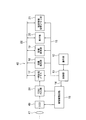
- FIG. 16 is a block diagram showing an internal circuit of a main part of the single-lens mirrorless camera 40.
- the processing means described above is configured by, for example, the CDS / ADC unit 24, the temporary storage memory 17, the image processing unit 18, and the like, and the storage unit is configured by the storage medium unit 19 or the like.
- the single lens mirrorless camera 40 is connected via the buses 14 and 15 to the operation unit 12, the control unit 13 connected to the operation unit 12, and the control signal output port of the control unit 13.
- the image pickup drive circuit 16 the temporary storage memory 17, the image processing unit 18, the storage medium unit 19, the display unit 20, and the setting information storage memory unit 21 are provided.
- the temporary storage memory 17, the image processing unit 18, the storage medium unit 19, the display unit 20, and the setting information storage memory unit 21 can input and output data with each other via the bus 22.
- a CCD 49 and a CDS / ADC unit 24 are connected to the imaging drive circuit 16.
- the operation unit 12 includes various input buttons and switches, and notifies the control unit 13 of event information input from the outside (camera user) via these buttons.
- the control unit 13 is a central processing unit composed of, for example, a CPU and has a built-in program memory (not shown) and controls the entire single-lens mirrorless camera 40 according to a program stored in the program memory.
- the CCD 49 is an image pickup element that is driven and controlled by the image pickup drive circuit 16, converts the light amount of each pixel of the object image formed via the photographing optical system 41 into an electric signal, and outputs the electric signal to the CDS / ADC unit 24.
- the CDS / ADC unit 24 amplifies the electrical signal input from the CCD 49 and performs analog / digital conversion, and raw video data (Bayer data, hereinafter referred to as RAW data) obtained by performing the amplification and digital conversion. Is output to the temporary storage memory 17.
- the temporary storage memory 17 is a buffer made of, for example, SDRAM, and is a memory device that temporarily stores RAW data output from the CDS / ADC unit 24.
- the image processing unit 18 reads out the RAW data stored in the temporary storage memory 17 or the RAW data stored in the storage medium unit 19, and includes distortion correction based on the image quality parameter designated by the control unit 13. It is a circuit that performs various image processing electrically.
- the storage medium unit 19 is detachably mounted with a card-type or stick-type recording medium made of, for example, a flash memory, and the RAW data transferred from the temporary storage memory 17 or the image processing unit 18 to these flash memories. Image-processed image data is recorded and held.
- the display unit 20 includes a liquid crystal display monitor 47 and the like, and displays captured RAW data, image data, an operation menu, and the like.
- the setting information storage memory unit 21 includes a ROM unit that stores various image quality parameters in advance, and a RAM unit that stores image quality parameters read from the ROM unit by an input operation of the operation unit 12.
- the single focus optical system of the present invention can also be used in an image pickup apparatus having a quick return mirror.
- FIG. 17 is a cross-sectional view of a projector as a projection apparatus.
- the projector 100 includes a light source unit 110, an illumination unit 120, an image forming unit 130, and a projection unit 140.
- the light source unit 110 includes a light source 111 and a reflecting member 112. Illumination light is emitted from the light source 111.
- the illumination light is white light.
- the illumination light is reflected by the reflecting member 112 and enters the illumination unit 120.
- the illumination unit 120 includes a first dichroic mirror 121, a second dichroic mirror 122, a third dichroic mirror 123, a first reflecting member 124, and a second reflecting member 125.
- the first dichroic mirror 121 transmits light in the red wavelength range (hereinafter referred to as “red light”) and reflects light in other wavelength ranges.
- the second dichroic mirror 122 reflects light in the green wavelength range (hereinafter referred to as “green light”) and transmits light in other wavelength ranges.
- the third dichroic mirror 123 reflects light in the blue wavelength range (hereinafter referred to as “blue light”) and transmits light in other wavelength ranges. Red light, green light, and blue light are incident on the image forming unit 130. Instead of the third dichroic mirror 123, a normal plane reflecting mirror may be used.
- the image forming unit 130 includes a first display element 131, a second display element 132, and a third display element 133.
- the first display element 131 is irradiated with red light through the first reflecting member 124.
- the second display element 132 is irradiated with green light.
- the third display element 133 is irradiated with blue light through the second reflecting member 125.
- the same image is displayed on the first display element 131, the second display element 132, and the third display element 133. Therefore, a red image is displayed on the first display element 131, a green image is displayed on the second display element 132, and a blue image is displayed on the third display element 133.
- the light emitted from the first display element 131, the second display element 132, and the third display element 133 is incident on the projection unit 140.
- the projection unit 140 includes a dichroic prism 141 and a projection optical system 142.
- the light emitted from the first display element 131, the second display element 132, and the third display element 133 is synthesized by the dichroic prism 141.
- the image forming unit 130 displays a red image, a green image, and a blue image. Three images are synthesized by the dichroic prism 141.
- Projection optical system 142 projects the combined three images at a predetermined position.
- this projection optical system 142 for example, the single focus optical system shown in the first to twelfth embodiments is used.
- the image forming unit 130 may be a light valve such as a DMD (digital mirror device).
- the light from the light source unit 110 may be reflected by the light valve, and the image from the light valve may be enlarged and projected by the projection unit 140.
- the projector 100 configured as described above, by adopting the single focus optical system of the present invention as the projection optical system 142, it is possible to project an image with low noise and high resolution over a wide projection range.
- the single focus optical system according to the present invention is suitable for a single focus optical system in which various aberrations are well corrected while having a wide angle of view and a small F number.
- the optical device according to the present invention is suitable for an imaging device that captures a wide imaging range with low noise and high resolution, and a projection device that projects an image with low noise and high resolution over a wide projection range.
Landscapes
- Physics & Mathematics (AREA)
- General Physics & Mathematics (AREA)
- Optics & Photonics (AREA)
- Engineering & Computer Science (AREA)
- Multimedia (AREA)
- Signal Processing (AREA)
- Lenses (AREA)
Abstract
La présente invention concerne un système optique simple foyer qui est constitué d'un premier groupe de lentilles G1 ayant un pouvoir réfringent positif, d'un deuxième groupe de lentilles G2 ayant un pouvoir réfringent négatif, et d'un troisième groupe de lentilles G3 ayant un pouvoir réfringent positif. Le premier groupe de lentilles G1 comporte au moins un premier sous-groupe, un deuxième sous-groupe et un troisième sous-groupe. Le premier sous-groupe comporte un composant de lentille négative. Le deuxième sous-groupe est formé de deux composants de lentille convexo-concave. Le troisième sous-groupe est formé d'une pluralité de composants de lentille positive. Le troisième groupe de lentilles G3 est formé d'un sous-groupe de côté avant G3a et d'un sous-groupe de côté arrière G3b. Le sous-groupe de côté avant G3a est formé d'un seul composant de lentille positive. Pendant la mise au point, le premier groupe de lentilles G1 est fixe, le deuxième groupe de lentilles G2 est mobile, et le sous-groupe de côté arrière G3b est fixe, au moins l'espace séparant le premier groupe de lentilles G1 et le deuxième groupe de lentilles G2 et l'espace séparant le deuxième groupe de lentilles G2 et le sous-groupe de côté avant G3a étant variables, et les espaces respectifs séparant des surfaces de lentille du premier groupe de lentilles G1, du deuxième groupe de lentilles G2, du sous-groupe de côté avant G3a et du sous-groupe de côté arrière G3b étant fixes.
Priority Applications (2)
| Application Number | Priority Date | Filing Date | Title |
|---|---|---|---|
| PCT/JP2015/065800 WO2016194112A1 (fr) | 2015-06-01 | 2015-06-01 | Système optique simple foyer et dispositif optique équipé de ce dernier |
| US15/800,383 US10191253B2 (en) | 2015-06-01 | 2017-11-01 | Single focus optical system and optical apparatus using the same |
Applications Claiming Priority (1)
| Application Number | Priority Date | Filing Date | Title |
|---|---|---|---|
| PCT/JP2015/065800 WO2016194112A1 (fr) | 2015-06-01 | 2015-06-01 | Système optique simple foyer et dispositif optique équipé de ce dernier |
Related Child Applications (1)
| Application Number | Title | Priority Date | Filing Date |
|---|---|---|---|
| US15/800,383 Continuation US10191253B2 (en) | 2015-06-01 | 2017-11-01 | Single focus optical system and optical apparatus using the same |
Publications (1)
| Publication Number | Publication Date |
|---|---|
| WO2016194112A1 true WO2016194112A1 (fr) | 2016-12-08 |
Family
ID=57441909
Family Applications (1)
| Application Number | Title | Priority Date | Filing Date |
|---|---|---|---|
| PCT/JP2015/065800 Ceased WO2016194112A1 (fr) | 2015-06-01 | 2015-06-01 | Système optique simple foyer et dispositif optique équipé de ce dernier |
Country Status (2)
| Country | Link |
|---|---|
| US (1) | US10191253B2 (fr) |
| WO (1) | WO2016194112A1 (fr) |
Cited By (1)
| Publication number | Priority date | Publication date | Assignee | Title |
|---|---|---|---|---|
| US11275234B2 (en) * | 2017-06-02 | 2022-03-15 | Dispelix Oy | Projection objective and waveguide display device |
Families Citing this family (7)
| Publication number | Priority date | Publication date | Assignee | Title |
|---|---|---|---|---|
| JP6558838B2 (ja) * | 2015-06-01 | 2019-08-14 | オリンパス株式会社 | 単焦点光学系及びそれを備えた光学装置 |
| JPWO2016194111A1 (ja) * | 2015-06-01 | 2018-03-22 | オリンパス株式会社 | 単焦点光学系及びそれを備えた光学装置 |
| JP6546656B2 (ja) * | 2015-06-01 | 2019-07-17 | オリンパス株式会社 | 単焦点光学系及びそれを備えた光学装置 |
| WO2016194110A1 (fr) * | 2015-06-01 | 2016-12-08 | オリンパス株式会社 | Système optique de focalisation unique et dispositif optique le comprenant |
| CN112639568B (zh) | 2019-03-01 | 2022-09-13 | 奥林巴斯株式会社 | 广角光学系统及具备该广角光学系统的摄像装置 |
| JP7061226B2 (ja) | 2019-03-01 | 2022-04-27 | オリンパス株式会社 | 広角光学系及びそれを備えた撮像装置 |
| WO2020178884A1 (fr) | 2019-03-01 | 2020-09-10 | オリンパス株式会社 | Système optique à grand angle et dispositif d'imagerie pourvu de celui-ci |
Citations (3)
| Publication number | Priority date | Publication date | Assignee | Title |
|---|---|---|---|---|
| JP2007225804A (ja) * | 2006-02-22 | 2007-09-06 | Mamiya Digital Imaging Co Ltd | レトロフォーカス型超広角レンズ |
| JP2012226309A (ja) * | 2011-04-07 | 2012-11-15 | Panasonic Corp | インナーフォーカスレンズ、交換レンズ装置及びカメラシステム |
| JP2013003324A (ja) * | 2011-06-16 | 2013-01-07 | Sigma Corp | 大口径レンズ |
Family Cites Families (16)
| Publication number | Priority date | Publication date | Assignee | Title |
|---|---|---|---|---|
| JP4217040B2 (ja) | 2002-09-10 | 2009-01-28 | 株式会社コシナ | 大口径広角レンズ |
| US7123421B1 (en) * | 2005-04-22 | 2006-10-17 | Panavision International, L.P. | Compact high performance zoom lens system |
| JP5111056B2 (ja) | 2007-10-30 | 2012-12-26 | キヤノン株式会社 | 光学系及びそれを有する撮像装置 |
| EP2149808B1 (fr) * | 2008-08-02 | 2015-11-25 | Ricoh Company, Ltd. | Objectif de type rétrofocus |
| JP5441377B2 (ja) | 2008-08-07 | 2014-03-12 | キヤノン株式会社 | 単焦点光学系及びそれを有する撮像装置 |
| JP5476881B2 (ja) | 2008-09-18 | 2014-04-23 | 株式会社ニコン | 広角レンズ、光学装置、広角レンズのフォーカシング方法 |
| JP5399175B2 (ja) | 2009-09-09 | 2014-01-29 | コニカミノルタ株式会社 | 広角レンズ,撮像光学装置及びデジタル機器 |
| JP2011209377A (ja) * | 2010-03-29 | 2011-10-20 | Olympus Imaging Corp | 結像光学系及びそれを用いた撮像装置 |
| JP5652349B2 (ja) * | 2011-07-25 | 2015-01-14 | 株式会社リコー | 広角レンズおよび全天球型撮像装置 |
| CN103907045B (zh) * | 2011-11-01 | 2016-06-22 | 富士胶片株式会社 | 物镜光学系统及使用了该物镜光学系统的内窥镜装置 |
| US9019621B2 (en) * | 2011-11-11 | 2015-04-28 | Olympus Corporation | Objective optical system and observation apparatus provided with the same |
| KR102018812B1 (ko) * | 2012-05-22 | 2019-09-05 | 삼성전자주식회사 | 망원렌즈 시스템 |
| JPWO2016194111A1 (ja) * | 2015-06-01 | 2018-03-22 | オリンパス株式会社 | 単焦点光学系及びそれを備えた光学装置 |
| JP6546656B2 (ja) * | 2015-06-01 | 2019-07-17 | オリンパス株式会社 | 単焦点光学系及びそれを備えた光学装置 |
| WO2016194110A1 (fr) * | 2015-06-01 | 2016-12-08 | オリンパス株式会社 | Système optique de focalisation unique et dispositif optique le comprenant |
| JP6558838B2 (ja) * | 2015-06-01 | 2019-08-14 | オリンパス株式会社 | 単焦点光学系及びそれを備えた光学装置 |
-
2015
- 2015-06-01 WO PCT/JP2015/065800 patent/WO2016194112A1/fr not_active Ceased
-
2017
- 2017-11-01 US US15/800,383 patent/US10191253B2/en not_active Expired - Fee Related
Patent Citations (3)
| Publication number | Priority date | Publication date | Assignee | Title |
|---|---|---|---|---|
| JP2007225804A (ja) * | 2006-02-22 | 2007-09-06 | Mamiya Digital Imaging Co Ltd | レトロフォーカス型超広角レンズ |
| JP2012226309A (ja) * | 2011-04-07 | 2012-11-15 | Panasonic Corp | インナーフォーカスレンズ、交換レンズ装置及びカメラシステム |
| JP2013003324A (ja) * | 2011-06-16 | 2013-01-07 | Sigma Corp | 大口径レンズ |
Cited By (1)
| Publication number | Priority date | Publication date | Assignee | Title |
|---|---|---|---|---|
| US11275234B2 (en) * | 2017-06-02 | 2022-03-15 | Dispelix Oy | Projection objective and waveguide display device |
Also Published As
| Publication number | Publication date |
|---|---|
| US20180067282A1 (en) | 2018-03-08 |
| US10191253B2 (en) | 2019-01-29 |
Similar Documents
| Publication | Publication Date | Title |
|---|---|---|
| JP6558838B2 (ja) | 単焦点光学系及びそれを備えた光学装置 | |
| JP6546656B2 (ja) | 単焦点光学系及びそれを備えた光学装置 | |
| JP5959294B2 (ja) | ズームレンズを備えた撮像装置 | |
| JP6383214B2 (ja) | 結像光学系及びそれを備えた光学装置 | |
| JP6400104B2 (ja) | 結像光学系及びそれを備えた光学装置 | |
| WO2016194111A1 (fr) | Système optique à foyer unique, et dispositif optique comportant ce système | |
| JP6605120B2 (ja) | 単焦点光学系及びそれを備えた光学装置 | |
| WO2016194112A1 (fr) | Système optique simple foyer et dispositif optique équipé de ce dernier | |
| JP2011123464A (ja) | ズームレンズおよびそれを備えた撮像装置 | |
| JP2010002684A (ja) | ズームレンズ及びそれを用いた撮像装置 | |
| JP2009037125A (ja) | 3群ズームレンズ及びそれを備えた撮像装置 | |
| WO2017130265A1 (fr) | Système optique à foyer unique, et dispositif optique muni de ce système | |
| JP2010217478A (ja) | ズームレンズ及びそれを備える撮像装置 | |
| JP2009020324A (ja) | 3群ズームレンズ及びそれを用いた撮像装置 | |
| JP4512359B2 (ja) | ズームレンズを備えたカメラ | |
| JP6523289B2 (ja) | 結像光学系及びそれを備えた光学装置 | |
| WO2016194110A1 (fr) | Système optique de focalisation unique et dispositif optique le comprenant | |
| JP5613070B2 (ja) | ズームレンズ及びそれを備えた撮像装置 | |
| JP2010060894A (ja) | ズームレンズおよびそれを備えた撮像装置 | |
| JP4489398B2 (ja) | ズームレンズ及びそれを用いた電子撮像装置 | |
| JP2003043358A (ja) | ズームレンズ | |
| JP6202836B2 (ja) | ズームレンズ及びそれを備えた撮像装置 | |
| JP2006308649A (ja) | 撮像装置 | |
| JP2006194974A (ja) | ズームレンズ及びそれを用いた撮像装置 | |
| JP5638973B2 (ja) | ズームレンズ及びそれを備えた撮像装置 |
Legal Events
| Date | Code | Title | Description |
|---|---|---|---|
| 121 | Ep: the epo has been informed by wipo that ep was designated in this application |
Ref document number: 15894147 Country of ref document: EP Kind code of ref document: A1 |
|
| NENP | Non-entry into the national phase |
Ref country code: DE |
|
| 122 | Ep: pct application non-entry in european phase |
Ref document number: 15894147 Country of ref document: EP Kind code of ref document: A1 |
|
| NENP | Non-entry into the national phase |
Ref country code: JP |